发动机耐久性试验大纲
- 格式:doc
- 大小:93.50 KB
- 文档页数:6

附件三车用发动机和非道路柴油机耐久试验要求(草稿)一、适用范围本要求适用于所有需要进行耐久试验的车用发动机、非道路柴油机机型。
二、耐久试验前1、企业提交“型式核准申报计划”,计划的格式和内容,参见附件一和附件二,申报计划中至少包括发动机相关信息和耐久试验计划等。
2、上述信息备案后,企业提交生产一致性保证计划书及附录A。
型式核准申报计划、计划书和附录A均备案后,方能进行耐久试验。
3、检测机构收到样机以及备案后的附录信息后,与企业相关人员一起核对样机排放关键部件配置与申报信息的符合性,核对一致后方能进行试验;且企业和检测机构应保证整个试验过程不得随意更换排放关键部件。
4、检测机构提交并保存样机相关照片:样机整机外观、样机铭牌(若有)、后处理系统及其铭牌和打刻内容照片等。
5、后处理含贵金属的,需要在我中心监督下做贵金属含量检测。
陶瓷载体的贵金属检测依据《车用陶瓷催化转化器中铂、钯、铑的测定电感耦合等离子体发射光谱法和电感耦合等离子体质谱法》(HJ509-2009)标准执行。
企业应随样机提交三套后处理装置,检测机构逐一核对铭牌内容无误后,打刻标识,并随机抽取一套用于贵金属检测,一套留存备查,一套用于试验。
三、耐久试验过程中1、保留并提交耐久试验的所有过程数据文件,记录至少包括并不限于以下关键参数(数据采集频次建议为1Hz,若有难度可参照以下执行):●发动机转速、扭矩/负荷(每个工况一次),一个循环每个工况点的油耗(每天开始和结束时各一次)●温度(每个工况一次):燃油,机油,中冷前,中冷后,涡轮后(排气温度),DOC和颗粒捕集器进口温度,SCR进出口温度●压力(每个工况一次):机油,中冷前,中冷后,涡轮后(排气背压),颗粒捕集器压降●发动机进气量●ECU应读取的参数(如适用),频率为1Hz◆EGR开/关,EGR冷却器进出口温度(如适用)◆OBD数据流中的发动机转速、扭矩◆尿素喷射开/关、尿素消耗量◆氧气传感器、氮氧化物传感器和氨气传感器信号(浓度)2、试验过程中,如果发动机排放关键部件出现问题,应暂停试验,并及时与我中心联系,不得擅自更换或者维修。
Performance engine durability is dependent on several supporting systems including the cooling system, fuel delivery system, ignition system and oiling system.If the support systems are not adequate, poor engine performance and possible engine failure could result.OILING SYSTEM CONSIDERATIONS/ COMMON PROBLEMS•Priming the oiling system before starting a new engine is crucial to engine life. This is important on initial start-up of a new engine and if a used engine has not been run for extended periods of time.•Does the oil pan have adequate capacity? Most performance vehicles require a 7 qt. minimum capacity. All engines will benefit from increasedoil pan capacity.•Does the oil pan have proper oil control baffling for the vehicle’s braking, acceleration and cornering capabilities? Road-race cars need oil control in four directions: braking, acceleration, LH cornering and RH cornering. Drag race cars need oil controlin two directions: braking and acceleration. Baffles must be designed to keep oil over the pickup screen at all times.•Is the pickup screen the proper distance from the bottom of the oil pan? If the oil pickup screen is too close to the bottom of the oil pan, it can cause cavitation. If it is too far away, it will cause the pump to draw air and minimize lubrication capacity. The pickup screen should be located .250" to .375" from the bottom of the pan. Does the design of the screen on the pickup tube create restrictions? We have seen some pickup tube screen designs that restrict oil flow as much as 75%. Wire mesh is good. Perforated metal is usually restrictive. Measure the wire size and calculate the flow area. Most aftermarket screens have less flow area than stock screens.•If using a remote oil filter mount or oil cooler, make sure that all of the components are large enough to eliminate any restrictions to oil flow. Many Cobra replica kit cars use componentsthat are too restrictive.•Undersize oil lines commonly restrict oil flow. •The more bends/turns in an oiling system,the more restrictions are created.•Poorly designed remote filter mounts and adapters can create restrictions.•Be sure that the oil cooler flows enough oilto meet the engine’s requirements.•Never reuse a used oil cooler. Debris gets trapped and cannot be cleaned out.•Poorly designed oil filters can cause a restriction. •Many oil systems only flow one way. Connecting the remote oil filter or oil cooler lines backwards can cause engine damage/failure.IGNITION SYSTEM CONSIDERATIONS/ COMMON PROBLEMS•The ignition system must deliver a properly timed spark. There are a lot of factors that determine when the spark should be delivered. The most common factors include: compression ratio, fuel quality, fuel octane rating, combustion chamber design, engine operating temperature, power adders such as NOS or supercharger, inlet air temp, altitude and load.•Avoid too much or too little timing for your engine combination.•Avoid hooking up the vacuum advance to intake manifold vacuum instead of ported vacuum. •Avoid inductive crossfire created by improper plugwire routing. Separate plug wires on cylinders thatfire in sequence.•Improper timing can damage pistons, rod bearings,head gaskets and many other engine parts.•Typical total mechanical advance timing at4000 rpm for Ford Racing Performance Partscrate engines: 5.0L: 36° to 38°, 347/351: 34° to 36°,392/460/514: 30° to 32°.FUEL DELIVERY CONSIDERATIONS•Size of fuel pump, size of fuel line, fuel pumpplacement, fuel filter placement, fuel filter size,injector size, fuel rail size, fuel pressure, jet sizeand baffling in the fuel tank.•Does the fuel system maintain full pressureat peak engine horsepower in high gear?Altitude, air temperature and fuel characteristicsincluding quality, specific gravity and octane rating willaffect your jetting requirements. Engine efficiency andBrake Specific Fuel Consumption (BSFC) also have aneffect. Here are some examples of a Holley® 750 CFM 4V.Jett i ng Jett i ngOctane Temp. Alt i tude Front Rear94 80 F 0 ft. 81 86Aviation 100LL 80 F 0 ft. 81 84110 Race 80 F 0 ft. 78 8394 80 F 3000 ft. 76 8194 80 F 6000 ft. 73 7794 40 F 0 ft. 84 8994 120 F 0 ft. 78 83As you can see by these examples, jet requirements canvary a lot depending on fuel, altitude and temperature.Oxygenated fuels are available in some states and candramatically affect your jetting requirements. Makesure you get your jetting correct. Aviation fuel is lighterand will require richening an engine in relationship to itsrequirement with pump gas. We have found in the dynotesting of our crate engines that 1 point richer on air/fuel ratio equals only a few percent less power. Runningan engine as lean as possible produces the best powerbut also increases combustion temperatures andthe chances of engine damage.COMMON PROBLEMS WITHFUEL DELIVERY SYSTEMS•Do not mount an EFI electric fuel pump so it hasto draw fuel from the tank. This creates negativepressure in the fuel line allowing the fuel to boilat a lower temperature.•The pump must be mounted in the tankor in a location so that it is gravity fed.•If the fuel rail is too small and you have largeinjectors, this can create a pulse in the fuel railallowing fuel starvation on some cylinders.•Fuel should be pushed through the fuel filter.Pulling fuel through a filter can cause cavitation.If a filter is to be used on the inlet of a rail-mountedfuel pump, a filter rating of 160 microns MINIMUMshould be used.•It takes approx. 1/2 lb of gasoline to support1 hp. This is commonly referred to as a .5 BSFC.You should always err in the safe direction oflarger when sizing your injectors and fuel pump.COOLING SYSTEM CONSIDERATIONS/COMMON PROBLEMS•Higher horsepower requires more cooling capacity.•When the fill point of the cooling system is notthe highest point, air pockets are created. Theair pockets then create hot spots, and the hot spotspromote improper combustion, which can causeengine failure.•Improper pulley size makes the fan and water pumpturn too slow or too fast. Production water pumpsare normally run at 20% over engine speed and donot perform well over 5000 engine rpm. Underdrivepulleys generally reduce water pump speed to 85%of engine rpm and may not provide enough waterflow to cool the engine.•The radiator must have enough area to dissipatethe heat being generated by the engine.•If the fan size is too small, it will not move enoughair across the radiator so it can properly dissipatethe heat being generated. Fan shrouds increasethe effectiveness of the fan significantly.•Radiator location can affect airflow through theradiator at different vehicle speeds.FLYWHEEL, CONVERTER ANDTRANSMISSION PROBLEMS•Installing the wrong flywheel for the balance factorof the engine will cause vibration and eventuallydamage the engine.•Wrong length input shaft or “stack-up height”can force the crank forward, damaging theengine thrust bearing.•Improperly installing the torque converter can forcethe crank forward, damaging the engine thrustbearing. This is most commonly caused byimproperly locating the torque convertor drain plugin the flexplate.•If the torque converter balloons, it can force thecrank forward, damaging the engine thrust bearingand the transmission. Most high-performance torqueconverters have anti-ballooning features.•Damage to the thrust bearing can happenin seconds!MISCELLANEOUS PROBLEMSTHAT CAN DAMAGE AN ENGINE•Dropping nuts, bolts, washers or foreignmaterials down the intake. We have seen thismore than once.•Reusing an intake off an engine that had brokenparts in a cylinder. The parts can get bounced upinto the intake manifold, carburetor or air cleaner(pieces of piston or piston rings, etc.). When youput your used intake on your new engine and startit, the pieces are drawn in and damage your engine.•Bead-blasting an EFI intake. You will NEVER getall of the blasting media out. When the engine isstarted, it draws the blasting media into thecylinders, destroying the engine.•Improperly torquing fasteners when installing newparts to your engine. Over-torquing of the intakemanifold bolts to the cylinder head on 302 and351W engines can cause head gasketsealing problems.•Installing distributor gears at the incorrect height,or using gears made of the wrong material. Wehave seen this a lot on remanufactured distributorsas well as popular aftermarket manufacturersof distributor assemblies. Use cast iron gearsfor cast iron flat tappet cams, and steel gearsfor steel hydraulic roller cams.ENGINE INSTALLATION AND TUNING TIPSENGINE DYNAMOMETER TESTING BASICSTYPES OF ENGINE DYNAMOMETERSThere are many types of dynamometers for testing engines: Water Brake, Eddy-Current, Electric…just to name a few. Depending on availability and engine application, Ford Racing utilizes any of those mentioned. The basic function of each of these dynamometers (referred to as dynos from this point forward) is the same. Each applies a different method to absorb the energy output of the engine. The engine output is measured as torque (work) and power is calculated. The energy produced by the engine is absorbed by the dyno and eventually dissipated as heat. Dynos measure this engine output over a range of engine conditions that vary with speed and load. Temperature, pressures, air/fuel ratio, water, oil, fuel and airflow measurements are elements of the test cell. The accurate measurement of these parameters is just as vital to good testing as the dyno itself. The test cell that houses a dyno can vary widely. Conditioned airflow, exhaust evacuation and fuel delivery must be adequate for the power level of the engine tested. Shortfalls in any of these areas can impact the integrity of the test.Ford Racing tests our crate engine offerings on any of the above-mentioned types of dynos. The type depends on test cell availability and type of engine application (street, sealed circle track, etc.). The engine is directly coupled to the dyno via a prop shaft. This type of testing yields brake power and torque. Test results are brake, horsepower and brake torque because measurements are taken directly from the crankshaft output.Water Brake dynos absorb energy by pumping water through various orifices. Speed and load are controlled through a feedback loop of inlet and outlet valves. Water Brake dynos are typically capable of absorbing very high engine outputs and rpm.Eddy-Current dynos rotate a disc through a magnetic field. This magnetic field can be varied in strength to control the rpm of the disc. These dynos are desirable for engine development due to very good rpm control. Electric dynos rotate a generator to absorbengine output; this yields an electric outputthat can be accurately measured. Typically,Electric dynos can be used to spin a non-firingengine and measure pumping losses andfriction. Those types of losses are difficult toascertain in conventional dyno testing.METHODS OF TESTINGOnce the engine is installed in a test cell,and all desired operating parameters areinstrumented, testing can begin. The dyno iscapable of absorbing an infinite number ofoperating conditions ranging from idle to WOT(wide open throttle) and idle rpm to rpm’sbeyond peak horsepower. In cases where thedyno is operated manually, the operator willset the rpm value via a controller. The operatorthen opens the throttle via a throttle actuatorand applies load to the dyno. As the throttle isopened further, the dyno will control the rpmto the set point and the load will increase untilfull throttle is reached. Many types of testingexist for evaluating engine performance. Crateengine testing consists of power development,durability, idle stability, etc.POWER TESTINGMethods for performing power tests orpower runs vary by dyno facility and engineapplication. Acceleration tests (sometimesreferred to as ramp tests) are controlledcompletely by dyno software through thedyno controller and throttle actuator. The rpmand transient times are programmed by theoperator and, once set, the controller takes theengine through the test. These tests typicallydo not let the engine stabilize at any givenspeed and data is collected throughout theramp. For example: The test would begin atidle. Slowly, the throttle will be opened andrpm controlled to the first chosen rpm testpoint. Eventually the throttle will reach WOT.From then, the rpm will increase at a given rateof rpm/time until the maximum test rpm isreached. Test data is recorded throughout theentire run. Finally the controller will close thethrottle and return the engine to idle.Another method of power testing is the stepmethod. This can be controlled manuallyor by an automated test where the dynosoftware controls the engine operation. Thedyno controller is set to the first rpm test pointand the throttle actuator is slowly openedto the full throttle point. The controller willmaintain the rpm of the engine to the setpoint. In the manual mode, the operator willobserve the data until stable and then record.In automated mode, the dyno will hold thethrottle and rpm for a set period of time andautomatically record the data. In either case,this testing provides good steady readings andmakes for good repeatable runs. The aboveprocedure will be repeated for all desired rpmtest points.Results of power testing are used in thedesign of crate engine packages and formarketing/sales. For further information oninterpreting results, see article on “CorrectionFactors, Observed and Corrected Horsepowerand Torque.”DURABILITY TESTINGDurability testing varies by engine applicationand configuration. The type of engine andwhere it will be used can influence the typeof durability testing greatly. For example,durability testing criteria for a sealed circletrack crate engine will be determined byminimum and maximum track conditions.Durability testing for a street application crateengine will be determined by peak torque andhorsepower for the given components. Testingconditions are typically WOT or high-loadconditions and variable rpm to cover as wide ofa range as possible. In short, durability testingcriteria vary, but the goal is the same. The goalis to produce an accelerated wear conditionthat exceeds the normal application of theengine as designed.RESULTSthe results to a standard set of conditions. SOME DEFINITIONS Observed Operating Conditions are measured near the entry of the carburetor or inlet air system of the engine. These conditions include inlet air temperature, wet bulb temperature and actual barometric pressure.Observed Torque is the measured torque value while the engine is running. It typically uses a calibrated load cell. This load cell measures the work the engine is doing in real time.The observed torque value is then used in calculating the observed horsepower value. Observed Horsepower represents how fast the work (generated by the engine) is being done. This is calculated by the following formula: (observed torque * rpm)/5252. Observed Barometric Pressure is atmospheric pressure measured near the engine air inlet. Observed Inlet Air Temperature isself-explanatory.Wet Bulb Temperature is the temperature achieved by evaporating water into the observed inlet air. This is accomplished by using a wick with one end in a vessel containing water and the other connected to a thermometeror thermocouple. This reading is used in calculating vapor pressure, humidity and, ultimately, correction factor.Corrected Torque is the measured torque times the correction factor.Corrected Horsepower is the measured horsepower times the correction factor. Corrected Barometric Pressure is the observed barometric pressure minus the corrected vapor pressure.Standard Barometric Pressure is stated in the definition of the correction factor.on a hot, muggy August day when a stormwas coming in. Also, engine tests performedin higher altitudes have lower observedbarometric pressure and engine performanceis lower.CORRECTION FACTORSSeveral correction factors exist and this articlewill deal with two of them.(1) SAE J1349, June 1990 Data correctedto 77° F and 29.31 in Hg 85% efficiency.(2) SAE J607, Data corrected to 60° Fand 29.92 in Hg.SAE J1349This formula utilizes the observed inlet airtemperature and wet bulb readings to calculatesaturated, current and corrected vaporpressure. The corrected vapor pressure issubtracted from the observed barometricpressure. It is subtracted because this pressureis due to water vapor in the air. This yieldscorrected barometric pressure.The conditions for correction are 77° F andbarometric pressure of 29.31 inches of mercury.Once the corrected barometric pressureis calculated and the observed inlet airtemperature is known, those values are pluggedinto the following formula. The correction factorformula is:C.F. = 1.18 #[(29.31/Corrected BarometricPressure) * {(Observed Inlet Air Temp+460)/(537)} ^.5]-.18SAE J607This formula utilizes the observed inlet airtemperature and wet bulb readings to calculatesaturated, current and corrected vapor pressure.The corrected vapor pressure is subtractedfrom the observed barometric pressure. It issubtracted because the pressure is due to waterstandard is the SAE J1349. This corrects to amore practical set of atmospheric conditionsand utilizes coefficients to compensate foran 85% mechanical efficiency. Please notetemperature is converted Rankine degrees inboth formulas.FYI about Ford Racing catalog torqueand horsepower ratingsFord Racing push rod crate engines are ratedat STP-corrected operating conditions. Thiscorrection factor is actually SAE J607, and alsoreferred to as “Racer Corrected.” Simplyspeaking, the STP correction factor takes theambient conditions and corrects the observeddata to 60° F, a barometric pressure of 29.93"of mercury and no correction for vaporpressure. This correction factor is used by mostdyno shops because it yields the highestnumbers to advertise.Ford Racing Modular crate engines are ratedat “SAE” corrected operating conditions. Thiscorrection factor is SAE J1349, and typicallyreferred as just “SAE.” This correction factor isused by automotive manufacturers to ratetorque and power for new vehicles. Thiscorrection factor adjusts the ambientoperating conditions and corrects theobserved data to 77° F, barometric pressure of29.31" of mercury and compensates forcorrected vapor pressure. Some of FordRacing's Modular crate engines are directvehicle replacement engines, and since theseengines/vehicles are originally advertised withSAE-corrected numbers, they also areadvertised in the catalog with SAE numbers.This keeps the engines' torque and powerratings consistent with O.E. advertised numbers.。

文件修改记录:修改日期修改人修改内容摘要编制审核 核准文件名称 YT156F 汽油机实验大纲文件编号 制定日期2011.8.24发行日期文件版本A一、目的对新/老产品测试的全面性、规范性起指导性。
二、适用范围适用汽油机的产品定型和检验试验三、名词解释无四、实验内容编号检测项目试验描述试验要求应用标准1基本检查检查试验要求中的各个项目a)发动机应按经规定程序批准的产品图样和技术文件制造;b)在产品技术文件中提供发动机的主要技术规格;c)按用户的要求提供必要的特性曲线;d)发动机在268~313K的自然环境温度下保正常工作;e)发动机应能在用户提出的纵横倾斜角度下可靠地工作;f)应提供发动机的外形安装图,注明安装尺寸、法兰及功率输出端的连接尺寸等;g)发动机防火应符合GB/T4556的规定;h)发动机安全应符合JB8890的规定;i)发动机各密封面及管接处,不允许漏气、漏油和漏水。
JB/T5135.3-20012起动性试验汽油机分别在常温(-5ºC~40ºC)、热机(汽油机在1.8kW/3600(r/min)工况下连续运转1h后停机)启动汽油机。
起动时间≤30s拉绳式起动器应能正常回位、棘爪分离和回位灵活。
JB/T5135.3-2001JB/T5135.1-20013最低空载稳定转速试验试验时不接测功机,逐步关闭化油器节气门位置,交替调整怠速混合气调节螺钉和节气门怠速限位螺钉,使汽油机达到最低空载稳定转速并运转5分钟,每分钟测量一次转速,计算六次的平均值和波动率,然后突然开大节气门,汽油机应不熄火。
1450±100r/minJB/T5135.3-2001JB/T5135.1-20014最大扭矩及相应转速检查在外特性试验中取最大扭矩及相应转速点。
5N.m/3000(r/min)JB/T5135.3-2001JB/T5135.1-20015标定功率及标定转速检查在最大功率转速下,逐步增加节气门开度及负荷,使汽油机达到最大功率,连续运转5min,开始和终了各测定一次通用小型汽油机各主要试验参数。
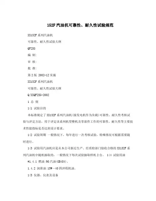
152F汽油机可靠性、耐久性试验规范XX152F系列汽油机可靠性、耐久性试验大纲QF2SG编制:审核:批准:第2版 2002-12实施XX152F系列汽油机可靠性、耐久性试验大纲Q/XXQF2SG-20021 总则1(1 试验目的本标准规定了XX152F系列汽油机(接发电机作为负载)可靠性、耐久性考核试验与评定方法,用于评定该系列机型整机及零部件工作的可靠性、耐久性等主要技术性能指标是否达到设计要求。
1(2 试验周期一般情况下,每年进行一次考核试验,特殊情况可根据需要随时进行。
1(3 试验用汽油机应是从本公司新近生产、经质检部门验收合格的XX152F系列汽油机中随机抽取的,一般情况下每次试验抽取样机2台。
1(4 试验用油#1.4.1 燃油:90汽油(GB484)。
1.4.2 润滑油:15W—40四冲程机油。
1(5 仪器、仪表及设备序号名称型号精度产地备注1 ZDC-9 直流电力测功机?0.5‰ 天津内燃机研究所2 2Kw 整机试验台 1, 自制3 水银温度计 ?1, 美国4 ST20 红外线测温仪5 DYM3 空盒气压表 ?10Pa6 干湿温度计 ?1?2 磨合与性能初试2.1样机的检查与调整2.1.1 试验前对样机进行全面检查并对各调整部位进行一次性调整。
2.1.2 检查并添加机油到规定液面(约370mL润滑油)。
2002-12-01发布 2002-12-15实施Q/XXQF2SG-20022.2 试验前的磨合规范2.2.1 冷磨合:按表1规范执行。
表1 冷磨合规范序号曲轴转速(rpm) 负载功率(Kw) 时间(h) 备注1 1500 02 2.2.2 热磨合:按表2a或表2b规范执行.累计运行四个循环,共计8h.表2a 热磨合规范(测试用50Hz发电机)序号曲轴转速( rpm) 负载功率(Kw) 时间(h) 附注1 2000 0 0.22 2800 0.4 0.53 3000 0.6 1.04 3000 1.0 0.3表2b 热磨合规范(测试用60Hz发电机)序号曲轴转速( rpm) 负载功率(Kw) 时间(h) 附注1 2000 0 0.22 3600 0.4 0.53 3600 0.8 1.04 3600 1.2 0.3 2(3 性能初试磨合循环结束后,若整机运行未出现任何异常现象,可直接按出厂验收规范对整机动力性和经济性进行初试测定。
汽车发动机耐久性试验报告1. 引言本报告旨在对汽车发动机的耐久性进行试验和评估。
试验旨在测试发动机在长时间运行和各种工作条件下的性能和可靠性。
通过对发动机的耐久性进行评估,可以提供对发动机寿命和质量的重要信息,进而改进设计和生产过程。
2. 试验方法本次试验采用以下方法对汽车发动机的耐久性进行评估:- 长时间运转测试:对发动机进行长时间运转,以模拟真实的使用情况。
- 负载测试:对发动机进行负载测试,以评估其在高负荷情况下的性能和稳定性。
- 温度测试:对发动机进行温度测试,以评估其在不同温度下的工作情况。
- 振动测试:对发动机进行振动测试,以检测其在振动环境下的工作状况。
3. 试验结果根据试验数据和分析结果,我们得出以下结论:- 发动机在长时间运转测试中表现良好,没有出现性能下降或故障。
- 发动机在负载测试中保持了稳定的输出功率,并没有出现过热或失效的情况。
- 发动机在不同温度下的测试中,能够适应宽范围的工作温度,并保持良好的性能。
- 发动机在振动测试中表现稳定,并未出现过多的振动或震动。
4. 结论和建议根据试验结果,我们可以得出以下结论和建议:- 汽车发动机在经过耐久性测试后表现良好,具备较高的可靠性和稳定性。
- 鉴于试验结果,建议继续进行发动机耐久性测试,并在实际生产中采取相应的措施来确保发动机的质量和寿命。
- 进一步的研究和发展可以在发动机设计和生产过程中引入更先进的技术,进一步提升发动机的耐久性和性能。
5. 致谢在此,我们要感谢参与本次试验和评估的所有工作人员和相关专家,在试验过程中提供的支持和帮助。
6. 参考文献[参考文献列表]。
发动机耐久性试验大纲一试验目的内燃机的工作寿命长短涉及到内燃机产品设计,制造,材料,工艺,制造过程中的质量管理以及用户使用维修的水平等条件。
因此,工作寿命是一个系统工程问题,在新产品开发定性试验或生产工艺,材料有重大变更时,要进行内燃机产品的耐久性试验,通过耐久试验,找出产品设计制造中哪些零件可靠性方面存在问题,以便进行改进设计或提高工艺水平,同时通过测量主要件的磨损量变化,可计算出发动机的使用寿命。
本试验是完整发动机在点火情况下的功能性试验。
其目的是检查高负荷部件(如:活塞,连杆,曲轴等)的可靠性,以及轴承,活塞环,气门机构的磨损,机油消耗量等的耐久情况。
为了检查全新设计的发动机的功能,或者将单一零部件加入到系列产品中时,必须要做耐久性试验。
二引用标准2.1 GB/T 18297-2001 《汽车发动机性能试验方法》2.2 GB/T 12679-90 《汽车发动机耐久性试验方法》2.3 GB/T 901-1998 《汽车发动机产品质量评定方法》三试验环境3.1 标准环境状况按GB/T 1105--1987的规定,标准环境状况为:大气压力:P=100KP(750mmHg)相对湿度:=30%环境温度:=298K(25℃)3.2 有效功率修正用下式修正有效功率P=aP其中:a-------修正系数P-------标准环境状况下的有效功率P-------现场环境下的有效功率修正系数计算式a=(99/p)其中:P=P------现场环境下的大气压力Pw-----现场环境下的炮和蒸汽压------现场环境温度下的相对湿度T-------现场环境温度四.试验对象,燃料五.装置与设备1耐久性试验应该在可点火运行的试验台架上进行。
需要以下设备仪器;a)发动机转速测量与监控装置b)发动机扭矩测量与监控装置C)发动机冷却水控制系统装置(整车设计的压力和流量)d)燃油消耗量测量仪e)漏气量测量仪f)爆震检测仪g)机油消耗量测量仪h)最多三十个温度传感器i)最多二十个压力传感器j)缸内最高压力传感器六.试验测量参数数据记录发动机应至少装配有以下功能和位置传感器七.试验方法(1)主程序1 发动机预运转在耐久性试验开始前,发动机应该进行完整预运转磨合过程。
2014届热能与动力工程(内燃机)专业毕业设计(论文)摘要发动机耐久性是发动机性能的一个重要指标,它关系到发动机能否达到使用者的寿命要求,同时它与可靠性有着密切联系,因此任何发动机设计者都不能忽略这一指标。
由此看来,针对耐久性的试验以及试验台架的开发都是十分重要也很必要的。
本文介绍的小型发动机耐久试验台架开发考虑到耐久性试验的特殊要求—工况单一、时间长,选用了与小型发动机功率相匹配的直流发电机来消耗发动机功率;选用了发动机发电机一体化的台架方案;选用了带传动作为发动机与发电机的传动方式。
关键词:发动机,耐久性,台架AbstractThe engine durability is an important index in its performance for it relation to whether the engine can reach the life requirements or not. At the same time, it has a close relationship with reliability, thus every engine desiginer should not neglect this. From this, it is not only crucial but also necessary for development which aim at durability test and testing bench.This paper introduces development of small engine's durability testing bench which considers about durability test's particular requirements, such as working conditions of single, long time, so it chooses a DC generator to use up engine's power; and it chooses the scheme of arrangement of test bench that engine-generator integration; and it chooses belt drive between engine and generator.Keywords:engine,durability,test bench目录摘要 (I)Abstract (II)前言 (1)研究背景及意义 (1)国内外研究现状 (2)参考文献大致来源 (2)第1章耐久性台架设计概述 (1)1.1设计的主要原理 (1)1.2设计的主要内容 (1)1.3解决的主要问题 (1)第2章耐久性试验对台架的要求 (2)2.1耐久性试验时间 (2)2.2耐久性试验工况 (3)2.3耐久性试验需测量的参数 (4)2.3.1转速n (4)2.3.2功率P e (4)2.3.3转矩T q (5)2.3.4温度T (5)2.3.5其他 (5)第3章耐久性台架的主要设计 (6)3.1台架能量流动 (6)3.2台架适用发动机 (6)3.3发电机选型 (7)3.4发动机与发电机的连接 (7)3.5发动机支撑部分的设计 (7)3.6发动机的工况控制和发电机的标定 (8)3.6.1发动机的工况控制 (8)3.6.2发电机标定 (8)第4章连接部分的设计 (9)4.1传动与联轴器 (9)2014届热能与动力工程(内燃机)专业毕业设计(论文)4.1.1齿轮传动 (9)4.1.2蜗杆传动 (9)4.1.3带传动 (9)4.1.4链传动 (9)4.1.5联轴器 (10)4.2连接方式的确定 (10)4.3带传动的选型、参数确定 (11)4.3.1带传动选型 (11)4.3.2带传动原始参数的确定 (11)4.4参数确定及其计算过程 (11)4.4.1求计算功率P1 (11)4.4.2选V带型号 (12)4.4.3求大、小带轮基准直径d2,d1 (13)4.4.4验算带速v (13)4.4.5求V带基准长度L d和中心距a (14)4.4.6验算小带轮包角α1 (14)4.4.7求V带根数z (14)4.4.8求作用在带轮轴上的压力 (16)4.4.9带轮结构设计 (17)第5章试验台部分的设计 (20)5.1实验台设计方案初定 (20)5.2支架的设计 (20)5.3发动机的固定与减振 (21)5.3.1发动机固定 (21)5.3.2发动机的减振 (21)5.4发电机固定方案 (22)5.5带传动张紧轮布置 (23)5.6台架总体布置图 (24)第6章基于直流发电机的工况控制原理 (26)6.1直流发电机稳态运行的基本方程式[19] (26)6.2发电机制动负载特性与发动机输出功率特性匹配与调控 (26)6.2.1 M/P控制模式(测功机恒扭矩/油门恒位置) (27)小型发动机耐久试验台架开发6.2.2 n/P控制模式(测功机恒转速/油门恒位置) (27)6.2.3 M/n控制模式(测功机恒扭矩/油门恒转速) (27)6.2.4n/M控制模式(测功机恒转速/油门恒扭矩) (27)6.3发电机的控制原理 (28)6.4台架各部分需进行的标定 (29)6.4.1带传动部分的效率η2 (29)6.4.2发电机发电效率η1 (29)结论 ...................................................................................................... 错误!未定义书签。

发动机耐久性试验大纲一试验目的内燃机的工作寿命长短涉及到内燃机产品设计,制造,材料,工艺,制造过程中的质量管理以及用户使用维修的水平等条件。
因此,工作寿命是一个系统工程问题,在新产品开发定性试验或生产工艺,材料有重大变更时,要进行内燃机产品的耐久性试验,通过耐久试验,找出产品设计制造中哪些零件可靠性方面存在问题,以便进行改进设计或提高工艺水平,同时通过测量主要件的磨损量变化,可计算出发动机的使用寿命。
本试验是完整发动机在点火情况下的功能性试验。
其目的是检查高负荷部件(如:活塞,连杆,曲轴等)的可靠性,以及轴承,活塞环,气门机构的磨损,机油消耗量等的耐久情况。
为了检查全新设计的发动机的功能,或者将单一零部件加入到系列产品中时,必须要做耐久性试验。
二引用标准2.1 GB/T 18297-2001 《汽车发动机性能试验方法》2.2 GB/T 12679-90 《汽车发动机耐久性试验方法》2.3 GB/T 901-1998 《汽车发动机产品质量评定方法》三试验环境3.1 标准环境状况按GB/T 1105--1987的规定,标准环境状况为:大气压力:P=100KP(750mmHg)相对湿度:=30%环境温度:=298K(25℃)3.2 有效功率修正用下式修正有效功率P=aP其中:a-------修正系数P-------标准环境状况下的有效功率P-------现场环境下的有效功率修正系数计算式a=(99/p)其中:P=P------现场环境下的大气压力Pw-----现场环境下的炮和蒸汽压------现场环境温度下的相对湿度T-------现场环境温度四.试验对象,燃料五.装置与设备1耐久性试验应该在可点火运行的试验台架上进行。
需要以下设备仪器;a)发动机转速测量与监控装置b)发动机扭矩测量与监控装置C)发动机冷却水控制系统装置(整车设计的压力和流量)d)燃油消耗量测量仪e)漏气量测量仪f)爆震检测仪g)机油消耗量测量仪h)最多三十个温度传感器i)最多二十个压力传感器j)缸内最高压力传感器六.试验测量参数数据记录发动机应至少装配有以下功能和位置传感器七.试验方法(1)主程序1 发动机预运转在耐久性试验开始前,发动机应该进行完整预运转磨合过程。
《汽车发动机原理(车用内燃机)》实验大纲指导老师王辉一、发动机试验的一般常识(一)试验前的准备1.了解试验目的;2.熟悉试验项目程序、试验方法、工况选定以及要求记录的项目;3.熟悉试验所用的仪器名称、规格、精度、安装方法;4.了解试验用燃油、润滑油牌号;5.明确水温、油温、排气温度的控制范围。
(二)试验中的注意事项1.试验中,应使发动机保持一定的热力状态,特别是影响发动机性能的参数,如:水温、油温,一般情况下保持在80~90℃为宜;2.发动机必须在工况稳定后方可测量记录参数,各参数测量同时进行。
主要参数,如油耗、转速、转矩等。
(三)操作注意事项1.起动前,应检查机油油量、燃油量及供水系统是否正常,各仪表是否正常;2.起动后,发动机怠速运转暖机,检查机油压力是否正常,发动机是否漏油、漏水、漏气,是否有异常声音,待油温、水温达到要求值后开始进行试验;3.调节工况时,加速、加载、减速、减载速度不要太快;4.运转中,注意测试仪表的指示,倾听发动机的运转声音,观察发动机外观,发现不正常现象应及时采取措施;5.停机时应缓慢卸掉负荷,再低速运转一段时间,待机油温度降至50℃以下后再停机;6.操作及在发动机周围活动时,应避开排气管、涡轮壳等高温区以防烫伤,在发动机运转时不要在其侧面停留。
(四)整理试验报告试验报告应该包含以下内容:1.试验目的、试验日期、试验概况等;2.试验所用仪表、仪器情况;3.试验所用发动机的主要技术规格,试验所用油料、附件及发动机有关调整参数,环境状况等;4.试验结果与分析。
试验结果用表格、曲线及文字三种形式表示,曲线绘制时,按以下步骤进行:(1) 数据整理及列表;(2) 选择横坐标与纵坐标及比例尺,曲线应占到图面的2/3以上,注意曲线要直观、美观,坐标要标注物理量名称、符号及单位;(3) 对不同参数测量值,可分别用“·”、“╳”、“△”、“⊙”等表示各点;(4) 用圆滑地曲线连接同一参数的不同点;(5) 对各曲线及符号要加以说明。
发动机耐久性试验工作总结
近年来,随着汽车行业的快速发展,发动机的耐久性成为了汽车制造商和消费者关注的焦点。
为了确保发动机的质量和性能,耐久性试验工作成为了必不可少的一环。
在过去的一段时间里,我们进行了一系列发动机耐久性试验工作,以验证发动机的可靠性和耐久性。
首先,我们进行了发动机零部件的耐久性试验。
通过对发动机的各个零部件进行疲劳试验和持久性试验,我们成功地验证了这些零部件在长时间工作下的稳定性和可靠性。
这为整个发动机的耐久性提供了坚实的基础。
其次,我们进行了整机发动机的耐久性试验。
在实际工作环境下,我们对发动机进行了长时间的运行试验,以模拟真实的使用情况。
通过监测和分析发动机的各项性能指标,我们成功地评估了发动机的耐久性和稳定性。
最后,我们进行了发动机在极端条件下的耐久性试验。
在高温、低温、高海拔等极端环境下,我们对发动机进行了严苛的试验,以验证其在极端条件下的可靠性和稳定性。
通过这些试验,我们进一步提高了发动机的耐久性和适应性。
总的来说,通过这些发动机耐久性试验工作,我们成功地验证了发动机的可靠性和耐久性,为汽车制造商提供了重要的参考数据。
未来,我们将继续深入研究和开展发动机耐久性试验工作,不断提升发动机的质量和性能,为汽车行业的发展贡献我们的力量。
发动机可靠性、耐久性试验大纲1试验目的全面检测发动机的各项性能技术参数是否满足设计和使用要求。
2 引用标准下列标准包含的条文,在编写本文时,所示版本均为有效,所有标准都会被修订,在实际使用中应探讨使用下列标准最新版本的可能性。
GB/T 725—1991 内燃机产品名称和型号编制规则GB/T 1105—1987 内燃机台架性能试验方法GB/T 1883—1989 往复活塞式内燃机术语GB 3100—1993 国际单位制及其应用JB/T 5135.3—2001 通用小型汽油机技术条件3 标准环境状况、功率修正3.1 标准环境状况按GB/T 1105—1987的规定,标准环境状况为:大气压力:p0=100KP a(750mmHg);相对湿度:φ0=30%;环境温度:T0=298K(25°C)3.2 有效功率的修正用下式修正有效功率P0=αa P …………………………………………… ( 1 )其中:αa———修正系数;P0———标准环境状况下的有效功率,Kw;P———现场环境状况下的有效功率,Kw。
修正系数的计算式αa=(99/P s)1.2(T/298)0.6……………………………( 2 )其中:P s=P-φP swP———现场环境状况下的大气压力,KP a;P sw———现场环境状况下的饱和蒸汽压力,KP a;φ———现场环境温度下的相对湿度;T———现场环境温度,T。
式(2)仅当0.93≤αa≤1.07和288K≤T≤308K及80KP a(600mmHg)≤P s≤110KP a(825mmHg)时才适用;否则应在试验报告中详细说明试验时的现场环境状况。
4 试验条件4.1 附件试验时发动机应装上必需的全部附件,附件的名称应在相应的试验记录表或者试验报告中详细记录。
如果试验台上不能安装原排气管、消声器时,应选择与原排气管、消声器的排气阻力相当的排气管道。
4.2 冷却发动机需使用自身的冷却系统进行冷却,不得另加冷却风源或者冷却介质进行冷却。
第六章可靠性、耐久性试验6.1 概述汽车可靠性是汽车最重要的性能之一,它是用户最为关心的性能,也关系到出车率和使用成,可靠性差,会直接影响产品销售。
可靠性与设计技术、全面质量管理、原材料和协作件质量的控制等密切相关。
汽车可靠性提高了,就意味着汽车整车技术水平提高了,因此,汽车可靠性行驶试验是一项必不可少的重要试验。
6.1.1 汽车可靠性定义所谓汽车可靠性,就是汽车产品在规定的条件下和规定的时间内完成规定功能的能力。
可靠性包括四个主要因素,即对象、规定条件、规定时间及规定功能。
对象即所研究的系统或构成,汽车可靠性试验中的对象即试验汽车。
规定的条件是指试验汽车的使用条件,诸如道路、载荷、气象、驾驶及维修等,以及存放条件。
规定的时间是指某一特征使用时间,例如,可靠性行驶试验时间、保用期、第一次大修里程及报废期等。
另外,汽车产品定型试验进行的可靠性行驶试验里程(5万km)也属于规定的时间范畴的。
规定的功能系指汽车使用说明书或设计任务书中明确的基本功能,例如动力性、燃料经济性、噪声性能及排放性能等。
对于不能完成功能,称为失效或者故障,也就是不可靠。
在汽车可靠性中,大体上将故障分为两大类,其一是零部件损坏导致汽车停驶或工作不正常的突发性故障,称为硬故障;其二是使汽车性能不稳定或性能下降到最低限度以下的渐衰型故障,称为软故障,两种故障都被认为是不能完成规定的功能的。
6.1.2 故障产品在规定的条件下和规定的时间内,丧失其规定功能的事件称为故障(也称失效)。
对于已经发生但尚未被发现的,或者是维修、拆检过程中发现的故障称为潜在故障。
汽车是一个复杂的系统,出现的故障模式多种多样,而各种故障对汽车危害度的分析,并按其对整车的危害程度进行分类。
而故障的危害度主要从其对人身安全的危害、对完成功能的影响及造成经济损失等方面进行衡量。
我国《汽车产品质量检验评定办法》中对故障的分类是按其造成整车致命损伤(人身重大伤亡及汽车严重损坏)的可能性(概率)进行简单分类的。
发动机耐久性试验工作总结近年来,随着汽车工业的快速发展,发动机的耐久性成为了汽车制造商和消费者关注的焦点之一。
为了确保发动机的可靠性和耐久性,汽车制造商们进行了大量的发动机耐久性试验工作。
在这篇文章中,我们将对发动机耐久性试验工作进行总结,以便更好地了解这一重要的工作内容。
首先,发动机耐久性试验工作是指对发动机在长时间运行过程中的性能和可靠性进行测试和评估的工作。
这项工作通常包括对发动机的各项性能指标进行测试,例如功率输出、燃油经济性、排放性能等。
同时,还需要对发动机在不同工况下的耐久性进行评估,例如高速行驶、急加速、急刹车等。
其次,发动机耐久性试验工作需要进行大量的实验数据采集和分析。
这些数据通常包括发动机的运行参数、温度、压力等多个方面的信息。
通过对这些数据的分析,可以更好地了解发动机在长时间运行过程中的性能特点和问题所在,为改进发动机设计提供参考。
此外,发动机耐久性试验工作还需要进行不同工况下的试验。
这些工况通常包括高温、低温、高海拔等极端环境条件下的试验。
通过对发动机在这些极端工况下的测试,可以更好地评估发动机的可靠性和耐久性,为发动机的改进和优化提供数据支持。
最后,发动机耐久性试验工作对汽车制造商来说具有非常重要的意义。
通过对发动机的耐久性进行充分的测试和评估,可以保证汽车在长时间使用过程中的可靠性和安全性。
同时,也可以为发动机的改进和优化提供重要的参考依据,提高汽车的性能和竞争力。
总之,发动机耐久性试验工作是汽车制造过程中非常重要的一环。
通过对发动机的各项性能指标进行测试和评估,可以更好地了解发动机的性能特点和问题所在,为发动机的改进和优化提供数据支持。
希望未来在这一领域的研究和实践能够不断取得新的突破和进展,为汽车工业的发展贡献更多的力量。
发动机耐久性试验大纲
一试验目的
内燃机的工作寿命长短涉及到内燃机产品设计,制造,材料,工艺,制造过程中的质量管理以及用户使用维修的水平等条件。
因此,工作寿命是一个系统工程问题,在新产品开发定性试验或生产工艺,材料有重大变更时,要进行内燃机产品的耐久性试验,通过耐久试验,找出产品设计制造中哪些零件可靠性方面存在问题,以便进行改进设计或提高工艺水平,同时通过测量主要件的磨损量变化,可计算出发动机的使用寿命。
本试验是完整发动机在点火情况下的功能性试验。
其目的是检查高负荷部件(如:活塞,连杆,曲轴等)的可靠性,以及轴承,活塞环,气门机构的磨损,机油消耗量等的耐久情况。
为了检查全新设计的发动机的功能,或者将单一零部件加入到系列产品中时,必须要做耐久性试验。
二引用标准
GB/T 18297-2001 《汽车发动机性能试验方法》
GB/T 12679-90 《汽车发动机耐久性试验方法》
GB/T 901-1998 《汽车发动机产品质量评定方法》
三试验环境
标准环境状况
按 GB/T 1105--1987的规定,标准环境状况为:
大气压力:P=100KP(750mmHg)
相对湿度: =30%
环境温度: =298K(25℃)
有效功率修正
用下式修正有效功率
P=aP
其中:a-------修正系数
P-------标准环境状况下的有效功率
P-------现场环境下的有效功率
修正系数计算式
a=(99/p)
其中:P=
P------现场环境下的大气压力
Pw-----现场环境下的炮和蒸汽压
------现场环境温度下的相对湿度
T-------现场环境温度
四.试验对象,燃料
(1)试验对象;
五.装置与设备
1耐久性试验应该在可点火运行的试验台架上进行。
需要以下设备仪器;
a)发动机转速测量与监控装置
b)发动机扭矩测量与监控装置
C)发动机冷却水控制系统装置(整车设计的压力和流量)
d)燃油消耗量测量仪
e)漏气量测量仪
f)爆震检测仪
g)机油消耗量测量仪
h)最多三十个温度传感器
i)最多二十个压力传感器
j)缸内最高压力传感器
六.试验测量参数数据记录
发动机应至少装配有以下功能和位置传感器
a)温度传感器测量位置及记录数值如图1
b)压力传感器位置如表2
c)除了温度压力外还应该测量以下发动机参数
七.试验方法
(1)主程序
1 发动机预运转
在耐久性试验开始前,发动机应该进行完整预运转磨合过程。
2 发动机性能试验
在耐久性试验前后都应该对发动机进行性能测试。
因此,因该测量一个负荷曲线,两个部分符合曲线和道托扭矩。
性能试验
在耐久性试验过程中应该进行全负荷曲线和部分负荷试验。
测量点规定如下 a)全负荷曲线
以每步500rpm从最低稳定转速(或1000rpm)到最高允许持续运转速度。
b) 部分负荷曲线
1)在最大扭矩转速从平均有效制动压力1,2,4bar按每步2bar一直到最大值。
2)在额定功率转速从平均有效制动压力1,2,4bar按每步2bar一直到最大值。
3耐久试验循环
其中100小时耐久性试验可非常迅速的给出发动机功能,危险零部件和磨损的重要信息。
600/800小时标准耐久性试验是发动机机械开发中最主要的试验,在结合低疲劳循环情况下高度包括了发动机的能力发挥。
动态耐久循环对于发动机进行高动态的运转是必要的。
此外,它一方面考核零部件的耐久性如深度热冲击试验。
,另一方面需要高负荷冲击的耐久循环如冷热冲击循环。
4)边界条件
耐久性试验开始前必须对测量装置进行标定。
发动机检查与保养间隔必须定义在检查时间表里,例如:
a) 磨合后的第一次机油和滤芯更换时间;
b) 接下来的每一确定的运转小时后或机油分析评定时刻的机油和滤芯更换时间;
c)每次事件或者机油更换时至少采集200ml机油样。
发动机停机限值必须认真定义在限值表中
发动机进行耐久性试验过程中,若发动机运行状态不佳,有可能导致试验中止,则可对发动及时进行分解检查。
(2)试验循环程序
3耐久循环试验程序;400小时冷热冲击循环
4耐久循环试验程序;300小时冷热冲击循环
八.试验结果分析
1 耐久性试验过程及试验后的程序
试验过程中的任何异常事件均应记录在试验记录/历史记录中。
另外,所有的失效和故障都
应该形成故障报告。
特殊零部件必须由供应商进行评价分析。
耐久试验完成后,发动机将拆解。
需测量记录重要紧固螺栓的拆解力矩。
所有零部件必须进行磨损和故障的目测检查。
a)对所有发动机部件进行磨损程度的等级评定。
b)所有主要试验零部件进行微分测量。
c)发动机和所有发动机零部件必须照相存档。
d)对机油消耗量,机油分析和活塞漏气量进行评估。
2 停止耐久性试验运转的标准
如果发动机在耐久试验过程中因超过了某一停机限制而停机,故障原因必须进行调查。
如果达到出现下面的情况,耐久性试验应终止。
a)预运转后额定功率点的发动机漏气量抽过了原来的两倍;
b)预运转后耐久循环的机油消耗量超过了其最初值得两倍;
c)功率或者扭矩减少了15%;
d) 燃油消耗量增加了15%
不允许对发动机主要零部件(如缸体,缸盖,动力传动部件,缸盖密封垫圈等)进行替换。
如有辅助部件失效(支架,喷油系统,涡轮增压器等),在某种情况下允许替换。
鸽格零部件的更换原因,件号,零部件编号必须记录在试验记录里面。
九.试验目标及结果要求
在耐久性试验后必须满足一下标准;
a) 发动机必须完好;
b) 试验后没有机油或者水的泄露;
c) 进气阀门和排气阀门没有水的泄露;
d)在耐久性试验过程中主要发动机零部件没有更换
e)在零部件评价表里没有超过“3”的等级
f)所有循环机油消耗量在一个固定范围内(缸套和换气系统完成后)。