英国Dart Sensors 甲醛传感器 中文数据手册
- 格式:doc
- 大小:174.00 KB
- 文档页数:6

bh1750FVI中文数据手册对于硬件开发者和制造商而言,BH1750FVI数字光照传感器是一个重要的元器件,其广泛应用于智能家居、智能照明、智能车辆以及各种智能设备中。
随着市场需求的不断增长,越来越多的开发者和制造商开始关注BH1750FVI数字光照传感器。
在使用这种传感器之前,了解其数据手册是非常必要的,本文就是一篇介绍BH1750FVI数字光照传感器中文数据手册的文章。
一、BH1750FVI简介BH1750FVI数字光照传感器是测量环境的光照强度的数字传感器,它能够通过I2C接口与MCU连接,输出数字信号。
该传感器采用亮度校准和温度校准的先进技术,能够在各种光线条件下提供准确的光照测量结果。
其超小的封装和低功耗特性,使得它成为了广泛应用于各种便携式智能设备、LED照明以及室内智能家居与办公环境的理想选择。
二、BH1750FVI特性BH1750FVI传感器特性如下:1.补偿功能:传感器采用了先进亮度校准和温度校准技术,能够提供高精度的光照测量结果。
2.数字接口:传感器具有I2C数字接口,可与微控制器(MCU)直接连接。
3.全面量程:传感器测量范围为0到65535(等于0.11到100000lx)。
4.低功耗特性:传感器在低功耗模式下只需消耗1uA的电流。
5.小型封装:BH1750FVI使用极小的封装,可在小型的智能设备中使用。
以上特性是BH1750FVI数字光照传感器非常重要的功能点。
三、BH1750FVI使用方法BH1750FVI数字光照传感器使用方法如下:1.将传感器连接到MCU的I2C总线上,并在MCU中使用相应的库函数初始化传感器。
2.读取传感器的光照强度值,这个值是一个16位的数字数据,可以直接在MCU上进行处理。
3.将读取到的数据转换为光照强度值(单位lx),具体转换公式可以参考BH1750FVI数据手册。
4.根据应用场景灵活调整读数器的分辨率和采样率。
四、BH1750FVI数据手册在使用BH1750FVI数字光照传感器的过程中,数据手册是非常重要的参考资料,其详细介绍了该传感器的特性和使用方法。

Leuze electronic GmbH + Co. KG Post-box 1111 D-73277 Owen-Teck Tel. +49 7021 5730www.leuze.deW e r e s e r v e t h e r i g h t t o m a k e c h a n g e s • 96_b 06e .f mz Retro-reflective photoelectric sensor for safe detection of transparent media (e.g.clear glass, PE, foil)z Reliable detection of the smallest gaps between transparent objectsz User controlled sensitivity adjustment with high resolutionz The autocollimation principle used ensures that the device functions reliably over the entire range (0…max.)z High switching frequency for detection of fast eventsz Connection via M12 connector or terminal compartment0…1.85m10 - 30 V DCAccessories:(available separately)z Mounting systems(BT 96, BT 96.1, UMS 96, BT 450.1-96)z M12 connectors (KD …)z Ready-made cables (K-D …)z Reflectorsz Reflective tapesz Alignment aid ARH96Dimensioned drawingA Indicator diode greenB Indicator diode yellowC Optical axisD Device plug M12x1E Screwed cable gland M16x1.5 for Ø5…10mmF Countersinking for SK nut M5, 4.2 deepG Connection terminalsH Cable entryI Sensitivity adjustment KLight/dark switchingElectrical connectionPRK 96Retro-reflective photoelectric sensors with polarisation filterPRK 96 M/P… - 06PRK 96 M/P… - 060603SpecificationsOptical dataTyp. operating range limit (TK(S) 50x50) 1)1)Typ. operating range limit: max. attainable range without performance reserve 0…1.85m Operating range 2)2)Operating range: recommended range with performance reserve0…1.5mLight source LED (modulated light)Wavelength660nm (visible red light/polarised)TimingSwitching frequency 1000Hz Response time0.5ms Delay before start-up≤200msElectrical dataOperating voltage U B 10…30VDC (incl. residual ripple) Residual ripple ≤15% of U B Bias current≤40mASwitching outputPNP transistorFunction characteristics light/dark switching (reversible)Signal voltage high/low ≥(U B -2V)/≤2V Output current max.100mASensitivity adjustable with 10-turn potentiometerIndicatorsLED green readyLED yellowclear glass - adjustment range 1transition from quickly flashing to slowly flashing coloured glass - adjustment range 2transition from cont. illuminated to quickly flashing other - adjustment range 3continuously illuminatedMechanical dataMetal housingHousing diecast zinc Optics cover glass Weight 380g Connection type terminals or M12 connector Environmental dataAmbient temp. (operation/storage)-20°C …+55°C/-40°C …+55°C Protective circuit 3)3)1=transient protection, 2=polarity reversal protection, 3=short circuit protection for all outputs, 4=interference blanking 1,2,3,4VDE safety class 4)4)Rating voltage 250VACII, all-insulated Protection class IP 67, IP 69K 5)5)IP 69K test acc. to DIN 40050 part 9 simulated, high pressure cleaning conditions without the use of additives,acids and bases are not part of the testLED class1 (acc. to EN 60825-1)Standards appliedIEC 60947-5-2Order guideDesignationPart No.With terminalsPRK 96M/P-1830-21500 28975With M12 connectorPRK 96M/P-1830-41500 80469TablesDiagramsRemarksz Integrated slit diaphragm: 3.7x20mmPRK 96。
Datasheet2Humidity and Temperature Wall Mount Transducers,SCT SeriesHoneywell Humidity and Temperature Wall Mount Transducers, SCT Series, are an ideal environmental solution for indoor applications such as building automation and HVAC systems in residential and office buildings. The SCT Series utilizesHoneywell HumidIcon™ humidity/temperature sensors to accurately and reliably sense humidity and temperature in the area to enhance user comfort.The SCT Series offers a variety of options and features. The transducers can be equipped with or without a legible LCDdisplay that shows the ambient temperature along with the relative humidity or dew point. The stylish cover trim is available in either silver or gold.Standard output of humidity and temperature is either 4 mA to 20 mA or 0 V to 10 V . The temperature output signal may also be configured with an NTC 10 kOhm, 20 kOhm or PT1000 sensor.INDUSTRY-STANDARD ACCURACY • STABILITY • RELIABILITYP otential ApplicationsINDUSTRIALClimate monitoring and control for: • Residential and office buildings• Production and manufacturing plants • Storerooms• Equipment cabinets • Testing environmentsFeatures•Enhanced accuracy:- ±4 %RH (10 %RH to 90 %RH at 25 °C),±5 %RH (10 %RH to 90 %RH at 5 °C to 50 °C)- Enables the customer to potentially reduce/eliminatetransmitter recalibration cost and supports and optimizes system accuracy and uptime• Long-term stability:- Humidity: ±0.05 %RH typ. and ±1.2 %RH max. drift overfive years- True temperature-compensated humidity elementenables customers to potentially reduce/eliminate the transmitter recalibration cost with enhanced stability over next best alternatives• Enhanced reliability: The humidity sensor element’s multilayerconstruction provides resistance to most applicationhazards such as dust, dirt, condensation, oils and common environmental chemicals, enhancing reliability• Standard humidity output: 4 mA to 20 mA or 0 V to 10 V • Cost-effective• Choice of cover trim color (silver or gold)• Full 0 %RH to 100 %RH measurement range • Available with or without LCD display3SCT SeriesTable 1. Humidity and Temperature PerformanceTable 2. Electrical SpecificationsTable 3. Environmental SpecificationsTable 4. Mechanical SpecificationsHumidity and Temperature Wall Mount TransducersFor example, SCTHWA43SDS de nes an SCT Series humidity and temperature transducer, wall mount, 4 mA to 20 mA output, 4 %RH humidity accuracy, 0.3 °C temperature accuracy/output type, -5 °C to 55 °C temperature range, LCD display, silver cover trim.Wall Mount T SeriesSCTTable 6. Order Guide for No Humidity (Temperature Only) Accuracy Figure 1. Nomenclature Tree 15 SCT SeriesFigure 2. Mounting Dimensions (For reference only: mm/in])With LCD DisplayWithout LCD Display4Humidity and Temperature Wall Mount Transducers Figure 3. DIP Switch Settings1, 22New setting with SW switch will be active once the unit is powered up..Sensing and Productivity Solutions Honeywell1985 Douglas Drive North Golden Valley, MN 55422 Find out moreHoneywell serves its customers through a worldwide network of sales offices, representatives and distributors. For application assistance, current specifications, pricing or name of thenearest Authorized Distributor, contact your local sales office.To learn more about Honeywell’s sensing and control products, call +1-815-235-6847 or 1-800-537-6945, visit , or e-mail inquiries to *********************32302444-A-EN IL50September 2015© 2015 Honeywell International Inc. All rights reserved.WARRANTY/REMEDYHoneywell warrants goods of its manufacture as being free of defective materials and faulty workmanship. Honeywell’s standard product warranty applies unless agreed to otherwise by Honeywell in writing; please refer to your order acknowledgement or consult your local sales office for specific warranty details. If warranted goods are returned to Honeywell during the period of coverage, Honeywell will repair or replace, at its option, without charge those items it finds defective. The foregoing is buyer’s sole remedy and is in lieu of all other warranties, expressed or implied, including those of merchantability and fitness for a particular purpose. In no event shall Honeywell be liable for consequential, special, or indirect damages.While we provide application assistance personally, through our literature and the Honeywell website, it is up to the customer to determine the suitability of the product in the application.Specifications may change without notice. The information we supply is believed to be accurate and reliable as of this printing. However, we assume no responsibility for its use.ADDITIONAL INFORMATIONThe following associated literature is available at : • Application Note• Installation Instructions。

Data SheetCO2/T/..CO2, Temperature, Humidity SensorsCO2/T/..CO2, Temperature, Humidity SensorsDescriptionThe CO2/T/.. series sensors measure the carbon dioxide concentration and air temperature. The range consists of duct and space sensors.Space sensors have an option for humidity measurement.Features▪High quality thermistor temperature sensor ▪Humidity measuring option for space sensor ▪IP67 housing (duct sensor)▪Two part terminals to facilitate wiring ▪24 Vac/dc supply▪Adjustable depth duct mounting flange optionPhysicalCO2/T/../S26 mm (1.02”)ACC/FLANGE/12MM/5CO2/T/..Data SheetFUNCTIONALITYThe CO2/T.. series carbon dioxide and temperature sensors can be used for a wide range of HVAC applications, operating over a 0 to 2000 ppm concentration CO 2 range. The CO 2 sensor offers an accuracy of ±50 ppm +2% of measured value.The CO2/T/D duct sensor, as a temperature working range is -20 °C to +60 °C (-4 to +140 °F) utilising a 10 kohm at 25 °C thermistor temperature sensing element. Recommended scaling is given for 0 °C to +40 °C (32 to +104 °F). The CO2/T/../S space sensor, has temperature measurement range is 0 °C to +40 °C (32 to +104 °F) utilising a 10 kohmat 25 °C (77 °F) thermistor temperature sensing element. The output signal is 0 to 10 V corresponding to 0 to +40 °C (32 to+104 °F) with an accuracy of ±0.3 °C (±0.54 °F).The humidity sensor option on the CO2/T/H/S has a measurement range of 0 to 95 %RH range with ±3 %RH accuracy over 30 to 70 %RH, and ±5 %RH accuracy over 10 to 90 %RH. The output signal is 0 to 10 V corresponding to 0 to 100 %RH.INPUT CHANNELS AND SENSOR SCALINGThe input channel must be set to the appropriate input type (see controller documentation for details) and the sensor type module must be set up with the correct scaling.The recommended method of setting the sensor scaling is to use the ‘Unique Sensor Reference’ provided, see below for details.The scaling parameters used by SET can be seen when the sensor type is configured. If this is not suitable you can create your own sensor scaling using SET.Carbon dioxide concentration: The input channel used should be set for voltage (V), and sensor scaling set as below.Controller Unique Sensor ReferenceIQ3, IQ4, IQeco, IQ2 >v2.1 C02 V IQ1, IQ2 <v2.0Refer to the IQ ConfigurationManual (90-1533)Temperature: The input channel used should be set for voltage(V) for CO2/T/./H/S, and Thermistor (T) for C02/T/D, and sensorthe scaling set as below.CO2/T/./H/S Controller Unique Sensor Reference IQ3, IQ4, IQeco, IQ2 >v2.1 Temp V 0+40 for value in °CTemp V +32+40 F for value in °F IQ1, IQ2 <v2.0Refer to the IQ Configuration Manual (90-1533)C02/T/DController Unique Sensor ReferenceIQ3, IQ4, IQeco, IQ2 >v2.1 Thermistor HTST DT for valuein °CThermistor HTST DT F for value in °FIQ1, IQ2 <v2.0Refer to the IQ ConfigurationManual (90-1533)Humidity: The input channel used should be set for voltage (V), and sensor scaling set as below.Controller Unique Sensor ReferenceIQ3, IQ4, IQeco, IQ2 >v2.1 Humidity V IQ1, IQ2 <v2.0Refer to the IQ ConfigurationManual (90-1533)INSTALLATIONCO2/T/../SThe sensor housing consists of a front panel and a backplate. The backplate can be separated from the front panel by inserting a screwdriver in the bottom slot and twisting.Choose an accessible location for the sensor where the surrounding air temperature is representative of the room. The backplate is designed so that it can be mounted on a back box or a standard recessed wall box, or surface mounted with mini-trunking by using a knockout in one of the sensor’s side walls.The installation involves:Choosing locationMounting sensor (via two screws - minimum) Connecting terminals Assembling sensor unitSetting up IQ input channels to voltage (V) for CO2 concentration, temperature, and humidity (if option fitted).Configuring IQ sensor modules TestingFull installation details are given in the CO2/T/../S InstallationInstructions (TG201171).Data Sheet CO2/T/..CO2/T/DChoose an accessible location where the sensor element will lie in the airstream to be measured. Ensure that there is no stratification in the airstream being measured (i.e. downstream of mixing dampers, heating coils, cooling coils). Mount the probe in the duct by screwing the sensor box directly onto the duct. It should be mounted in the orientation indicated on the label on the side of the unit so that the air flows into and out of the inlet/outlet slots. The probe requires a 15 mm (0.59”) hole cut into the duct. The sensor box may be screwed directly to the duct using 2 screws at 85 mm (3.35”) centres. The installation involves:Choosing locationDrilling sensor probe hole Drilling fixing holesMounting sensor on prepared location Removing sensor lidFeeding IQ cables through gland Wiring cablesReplacing sensor lidSetting up IQ input channels to voltage (V) for CO 2 concentration and to thermistor (T) for temperature.Configuring IQ sensor modules Testing sensorThe optional mounting flange enables the probe depth to be adjusted by tightening the flange clamp to secure the position. It is screwed to the duct using 4 off screws at 45 mm (1.77”) centres.Full installation details are given in the CO2/T/D Installation Instructions (TG201170).COMPATIBILITYWhen connecting to an IQ4 controller the following limits apply if the IQ4 is to provide power. If the sensor is powered from a separate power supply these limits do not apply.Controller Max No of CO2 sensorsIQ41x 0IQ422/24V 1IQ422/230V 3IQ4E/230V6ORDER CODESCO2/T/D Duct carbon dioxide concentration and temperature sensor CO2/T/S Space carbon dioxide concentration and temperature sensorCO2/T/H/SSpace carbon dioxide concentration, temperature, and humidity sensor ACC/FLANGE/12MM/5Adjustable depth, duct mounting flange - pack of 5DISPOSALDirect MountingCO2/T/..Data SheetPlease send any comments about this or any other Trend technical ***************************************© 2021 Honeywell Products and Solutions SARL, Connected Building Division. All rights reserved. Manufactured for and on behalf of the Connected Building Division of Honeywell Products and Solutions SARL, Z.A. La Pièce, 16, 1180 Rolle, Switzerland by its Authorized Representative, Trend Control Systems Limited.Trend Control Systems Limited reserves the right to revise this publication from time to time and make changes to the content hereof without obligation to notify any person of such revisions or changes.Trend Control Systems LimitedSt. Mark’s Court, North Street, Horsham, West Sussex, RH12 1BW, UK. Tel: +44 (0)1403 211888, SPECIFICATIONSCO 2 MEASUREMENTWorking range :0 to 2000 ppm CO 2 concentrationSignal:0 to 10 V for 0 to 2000 ppm into >10 kohmAccuracy :±(50 ppm + 2% of measured value) at23 °C (73.4 °F) and 1013 mbarTemperature influence :2 ppm/°C at 0 ppm typical Pressure influence :1 ppm/1 mbar at 1000 ppm approx.(physical effect)Resolution :0.2 ppm (internal 15 bit)Long-term stability :20 ppm/year typical Response time :t 90 < = 250 sTEMPERATURE MEASUREMENTWorking range :-20 to +60 °C (-4 to +140 °F)Sensing element :Trend standard thermistor 10 kohm at 25 °C (77 °F)SignalCO2/T/D :thermistor (resistance)CO2/T/../S :0 to 10 V for 0 to +40 °C (32 to 104 °F) into >10 kohmAccuracyCO2/T/../S :±0.3 °C (±0.54 °F) at 23 °C (79 °F) and 1013 mbar with 24 Vdc supply (±0.55 °C, ±1 °F with 20 to 28 Vdc supply)ResolutionCO2/T/../S:0.005 °C, 0.009 °F (internal 15 bit)HUMIDITY MEASUREMENT (CO2/T/H/.../S only)Working range:0 to 95 %RH (non condensing)Signal :0 to 10 V for 0 to 100 %RH into >10 kohmAccuracy :±3 %RH over range 30 to 70 %RH,±5 %RH over range 10 to 90 %RH, both at 23 °C (79 °F) and 1013 mbar Resolution:0.01 %RH (internal 15 bit)ELECTRICALPower input voltage :24 Vdc (15 to 35 Vdc), 24 Vac (±20%)Power input current:13 mA dc typical (while not measuring) 350 mA dc at 23 °C (77 °F) for 350 ms (during measurement)MECHANICALMaterial CO2/T/DEnclosure :Impact resistant ABSProbe :Polycarbonate (flammability HB)Filter:PTFE membrane filterDuct mounting flange :Polycarbonate (flammability HB)Material CO2/T/../SEnclosure:Flame retardant (V0) ABSDimensions CO2/T/DDuct probe:258 mm, 10.16” (including filter) x 12 mm, 0.75” (diameter)Head :105 mm (4.13”) x 57 mm (2.24”) x97 mm (3.82”)Fixing centres :85 mm ((3.35”)Dimensions CO2/T/../S :86 mm (3.39”) x 86 mm (3.39”) x26 mm (1.02”)WeightCO2/T/D :200 g approximately CO2/T/../S :150 g approximately Connections :2 part 6 pole screw terminals for0.2 mm 2 to 1.5 mm 2 cross section area (24 to 16 AWG) cableENVIRONMENTALProtectionCO2/T/D:IP65 except filter cap and air inlet/outletCO2/T/../S :IP20CE compatibility :EN61326-1, EN61326-2-3Storage Temperature :-20 to +60 °C (-4 to +140 °F)Humidity :0 to 95 %RH, non condensing。
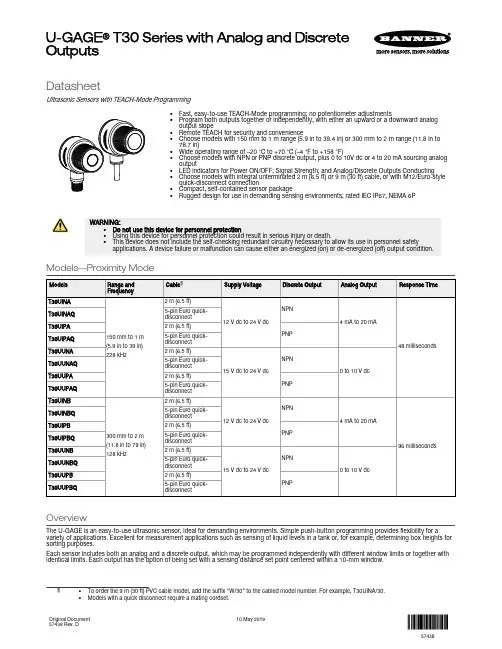
DatasheetUltrasonic Sensors with TEACH-Mode Programming•Fast, easy-to-use TEACH-Mode programming; no potentiometer adjustments•Program both outputs together or independently, with either an upward or a downward analogoutput slope•Remote TEACH for security and convenience•Choose models with 150 mm to 1 m range (5.9 in to 39.4 in) or 300 mm to 2 m range (11.8 in to78.7 in)•Wide operating range of –20 °C to +70 °C (–4 °F to +158 °F)•Choose models with NPN or PNP discrete output, plus 0 to 10V dc or 4 to 20 mA sourcing analogoutput•LED indicators for Power ON/OFF; Signal Strength; and Analog/Discrete Outputs Conducting•Choose models with integral unterminated 2 m (6.5 ft) or 9 m (30 ft) cable, or with M12/Euro-stylequick-disconnect connection•Compact, self-contained sensor package•Rugged design for use in demanding sensing environments; rated IEC IP67, NEMA 6PWARNING:•Do not use this device for personnel protection•Using this device for personnel protection could result in serious injury or death.•This device does not include the self-checking redundant circuitry necessary to allow its use in personnel safety applications. A device failure or malfunction can cause either an energized (on) or de-energized (off) output condition.Models—Proximity ModeOverviewThe U-GAGE is an easy-to-use ultrasonic sensor, ideal for demanding environments. Simple push-button programming provides flexibility for a variety of applications. Excellent for measurement applications such as sensing of liquid levels in a tank or, for example, determining box heights for sorting purposes.Each sensor includes both an analog and a discrete output, which may be programmed independently with different window limits or together with identical limits. Each output has the option of being set with a sensing distance set point centered within a 10-mm window.U-GAGE® T30 Series with Analog and DiscreteOutputsFeatures and IndicatorsU-GAGE Figure 1. U-GAGE T30 Series sensor programming push buttons and indicatorsNote: All LED indicators momentarily turn off when the sensor changes state between Program and Run modes.The U-GAGE sensor has four LED indicators. The red Signal LED indicates the strength and condition of the sensor's incoming signal. Each amberOutput LED, whether analog or discrete, turns on when a target is sensed within the programmed window limits. The green Power ON/OFF LED indicates the operating status of the sensor. There are two modes of indication for the LED indicators: Run Mode and Program Mode.In Run mode:In Program mode:WiringNPN*It is recommended that the shield wire be connected to either earth ground or DC common.–+ PNP*It is recommended that the shield wire be connected to either earth ground or DC common.–+Cabled wiring diagrams are shown. Quick disconnect wiring diagrams are functionally identical.Configuring a Sensor Window LimitsWindow limits can be taught to the sensor in several ways, using either the push buttons on the back of the sensor or remote input.Note: When the sensor changes state between PROGRAM and RUN modes, all of the LED indicators turn OFF momentarily,before the appropriate LEDs come ON as described below. The sensing window limits expand temporarily to full scale (max range) during PROGRAM mode.Remote InputTo program the sensor remotely or to disable the keypad, use the Remote Programming function. In addition to programming the sensor, use the remote input to disable the buttons for security, preventing unauthorized or accidental programming changes. Connect the gray wire of the sensor to +12 V dc to 24 V dc, with a remote programming switch connected between them.Note: The impedance of the remote teach input is 55 kΩ.Programming is accomplished by following the sequence of input pulses. The duration of each pulse (corresponding to a push button “click”), and the period between multiple pulses, are defined as: 0.04 seconds < T < 0.8 seconds.Note: To exit PROGRAM mode without saving any changes, hold the Remote line high > 2 seconds (before teaching the second limit). The sensor reverts to the last saved program.LimitOutput 2 Limits OnlyLimitLimitPush Button Locked out(or Enabled)Output 1Limits OnlyLimit Both OutputsTogetherPush ButtonLockout (or Enable)0.04 sec < T < 0.8 secFigure 2. Timing programs for remote TEACH programmingGeneral Notes on Configuration•The sensor returns to Run mode if the first TEACH condition is not registered within 120 seconds.•After the first limit is taught, the sensor remains in Program mode until the TEACH sequence is finished.•To exit PROGRAM mode without saving any changes, press and hold the programming push button > 2 seconds or hold the Remote line high > 2 seconds (before teaching the second limit). The sensor reverts to the last saved program.Configuring Limits for Either Analog or Discrete OutputNote: To exit PROGRAM mode without saving any changes, press and hold the programming push button > 2 seconds or hold the Remote line high > 2 seconds (before teaching the second limit). The sensor reverts to the last saved program.1.Choose the output for the first set of window limits (analog or discrete).2.Configure the first limit.3.Teach the second limit.4.Repeat for the other output (analog or discrete) if a second output is desired.Configure Analog or Discrete Limits Using the Auto-Zero FeatureFor some applications, a sensing distance set point centered within a minimum sensing window may be required. The TEACH procedure for this application is simple: configuring the same limit twice causes the sensor to program a 10-mm window centered on the position taught (position ±5mm).Note: The sensor allows for some forgiveness in this procedure. If the two limits are not exactly the same (but closer than the minimum 10-mm window required), the sensor places the set point at the average of the two limits.Configuring Identical Limits for Both Analog and Discrete Outputs SimultaneouslyTo set both the analog and the discrete outputs at exactly the same limits, both may be set simultaneously.1.Enter PROGRAM mode.2.Configure the first limit.3.Teach the second limit.Push Button LockoutAnalog OutputThe U-GAGE T30 Series series sensor may be configured for either a positive or a negative output slope, based on which condition is taught first (see Figure 3 on page 6). If the near limit is taught first, the slope is positive; if the far limit is taught first, the slope is negative. Banner’s scalable analog output automatically distributes the output signal over the width of the programmed sensing window.The U-GAGE T30 Series also features a 2-second hold upon loss of the received analog signal, which is useful for harsh and unstable applications.In the event of analog signal loss for longer than 2 seconds, the analog output goes to 3.6 mA or 0 V dc, which may be used to trigger an alarm.Current-Sourcing Models Target Position Positive SlopeNear WindowFar WindowA n a l o g O u t p u t (m A )204Negative SlopeVoltage-Sourcing ModelsTarget PositionPositive SlopeNearWindowFar WindowV o l t a g e O u t p u t (V d c )100Negative SlopeFigure 3. Positive and Negative Output SlopesNote: The analog current output tracks slightly past each window limit (from 3.8 to 20.5 mA).Self-Diagnostic Error ModeIn the unlikely event of a microprocessor memory error, all of the LEDs will flash in sequence. If this occurs, the setup parameters have been lost and the sensor may be corrupt. Contact Banner Engineering for further information.SpecificationsProximity Mode RangeA suffix models: 150 mm (5.9 in) minimum near limit; 1 m (39 in) maximum far limitB suffix models: 300 mm (11.8 in) minimum near limit; 2 m (79 in) maximum far limit Supply VoltageCurrent-sourcing analog output models: 12 V dc to 24 V dc (10% maximum ripple) at 90 mA, exclusive of loadVoltage-sourcing analog output models: 15 V dc to 24V dc (10% maximum ripple) at 90 mA, exclusive of load Supply Protection CircuitryProtected against reverse polarity and transient voltages Output ConfigurationsDiscrete (switched) output: SPST solid-state switch conducts when target is sensed within sensing window; choose NPN or PNP modelsAnalog output: Choose 0 V dc to 10 V dc sourcing or 4 mA to 20 mA sourcing output models; output slope may be selected via TEACH sequence (see Window Limits on page 3)Output RatingsDiscrete (switched) output: 100 mA maximumOff-state leakage current: less than 5 microampsOn-state saturation voltage: less than 1 V at 10 mA and less than 1.5 V at 100 mA Analog output:Voltage sourcing: 0 V dc to 10 V dc (at 1K Ω minimum resistance)Current sourcing: 4 to 20 mA, 1 Ω to Rmax Rmax = V supply - 7V / 20 mA Output Protection CircuitryProtected against output short-circuit, continuous overload, transient overvoltages,and false pulse on power-up Output Response Time Discrete output:“A” suffix models: 48 milliseconds “B” suffix models: 96 milliseconds Analog output:“A” suffix models: 48 milliseconds average, 16-millisecond update “B”suffix models: 96 milliseconds average, 32-millisecond update ConstructionMolded reinforced thermoplastic polyester housingSensing PerformanceNote: Specified using a 10 cm × 10 cm aluminum target at 25 ºC under fixed sensing conditions.Analog sensing resolution: ±0.25% of measured distance Analog linearity: ±0.5% of full-scale sensing range Sensing repeatability: ±0.25% of distance Minimum window size: 10 mm (0.4 in)Hysteresis of discrete output: 2.5 mm (0.10 in)AdjustmentsSensing window limits (analog or discrete): TEACH-mode programming of near and far window limits may be set using the push buttons on the sensor or remotely via TEACH input (see Configuring a Sensor on page 3). Discrete and analog window limits may be programmed separately, or together.Analog output slope: the first limit taught is assigned to the minimum output value (4mA or 0V)Environmental RatingLeakproof design is rated IEC IP67; NEMA 6P Connections2 m (6.5 ft) or 9 m (30 ft) 5-conductor PVC-covered attached cable, or 5-pin Euro-style quick-disconnect fitting Operating ConditionsTemperature: –20 °C to +70 °C (–4 °F to +158 °F)100% maximum relative humidity Application NotesObjects passing inside the specified near limit will produce a false response.Note: For more information about out-of-range and signal loss response of the analog output, see Analog Output on page 5.Vibration and Mechanical ShockAll models meet MIL-STD-202F, Method 201A (Vibration: 10 Hz to 60 Hz maximum,0.06 inch (1.52 mm) double amplitude, 10G maximum acceleration) requirements. Also meets IEC 60947-5-2 (Shock: 30G 11 ms duration, half sine wave) requirements.CertificationsDimensionsM30 x 1.5ThreadQuick-Disconnect ModelsPerformance Curves00200 mm (8.0 in)400 mm (16.0 in)600 mm (24.0 in)800 mm (32.0 in)1000 mm (40.0 in)50501001001501502002002.0 in 2.0 in 4.0 in4.0 in 6.0 in 6.0 in8.0 in 8.0 in DISTANCEW I D T H (m m )Figure 4. A Models 00400 mm (16.0 in)800 mm (32.0 in)1200 mm (48.0 in)1600 mm (64.0 in)2000 mm (80.0 in)10010020020030030040040004.0 in 4.0 in 8.0 in 8.0 in 12.0 in 12.0 in16.0 in 16.0 inDISTANCEWI D T H (m m )Figure 5. B Models05050100100150150200200(8.0 in)(16.0 in)(24.0 in)(32.0 in)(40.0 in)2.0 in 2.0 in 4.0 in4.0 in 6.0 in 6.0 in8.0 in 8.0 in DISTANCE W I D T H (m m )Figure 6. A Models 010*******200300300400400DISTANCE400 mm (16.0 in)800 mm (32.0 in)1200 mm (48.0 in)1600 mm (64.0 in)2000 mm (80.0 in)04.0 in 4.0 in 8.0 in 8.0 in 12.0 in12.0 in16.0 in 16.0 inW I D T H (m m )Figure 7. B ModelsAccessories CordsetsBracketsAll measurements are in mm.Banner Engineering Corp. Limited WarrantyBanner Engineering Corp. warrants its products to be free from defects in material and workmanship for one year following the date of shipment. Banner Engineering Corp. will repair or replace, free of charge, any product of its manufacture which, at the time it is returned to the factory, is found to have been defective during the warranty period. This warranty does not cover damage or liability for misuse, abuse, or the improper application or installation of the Banner product.THIS LIMITED WARRANTY IS EXCLUSIVE AND IN LIEU OF ALL OTHER WARRANTIES WHETHER EXPRESS OR IMPLIED (INCLUDING, WITHOUT LIMITATION, ANY WARRANTY OF MERCHANTABILITY OR FITNESS FOR A PARTICULAR PURPOSE), AND WHETHER ARISING UNDER COURSE OF PERFORMANCE, COURSE OF DEALING OR TRADE USAGE.This Warranty is exclusive and limited to repair or, at the discretion of Banner Engineering Corp., replacement. IN NO EVENT SHALL BANNER ENGINEERING CORP. BE LIABLE TO BUYER OR ANY OTHER PERSON OR ENTITY FOR ANY EXTRA COSTS, EXPENSES, LOSSES, LOSS OF PROFITS, OR ANY INCIDENTAL, CONSEQUENTIAL OR SPECIAL DAMAGES RESULTING FROM ANY PRODUCT DEFECT OR FROM THE USE OR INABILITY TO USE THE PRODUCT, WHETHER ARISING IN CONTRACT OR WARRANTY, STATUTE, TORT, STRICT LIABILITY, NEGLIGENCE, OR OTHERWISE.Banner Engineering Corp. reserves the right to change, modify or improve the design of the product without assuming any obligations or liabilities relating to any product previously manufactured by Banner Engineering Corp. Any misuse, abuse, or improper application or installation of this product or use of the product for personal protection applications when the product is identified as not intended for such purposes will void the product warranty. Any modifications to this product without prior express approval by Banner Engineering Corp will void the product warranties. All specifications published in this document are subject to change; Banner reserves the right to modify product specifications or update documentation at any time. Specifications and product information in English supersede that which is provided in any other language. For the most recent version of any documentation, refer to: .For patent information, see /patents.。
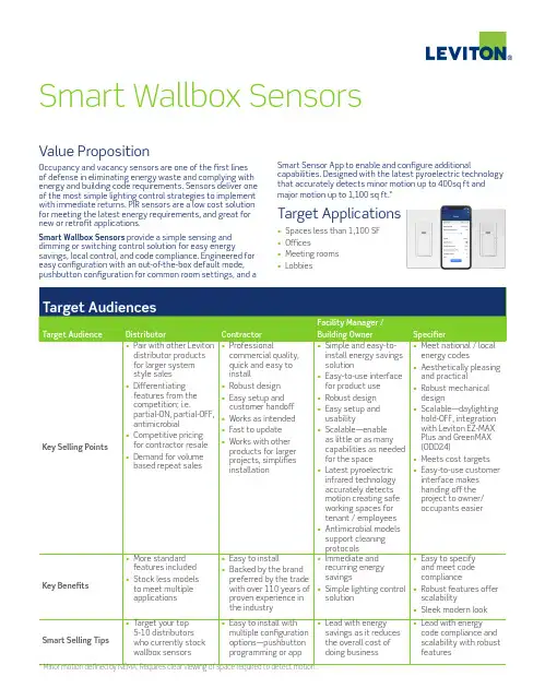
Value PropositionOccupancy and vacancy sensors are one of the first lines of defense in eliminating energy waste and complying with energy and building code requirements. Sensors deliver one of the most simple lighting control strategies to implement with immediate returns. PIR sensors are a low cost solution for meeting the latest energy requirements, and great for new or retrofit applications.Smart Wallbox Sensors provide a simple sensing and dimming or switching control solution for easy energysavings, local control, and code compliance. Engineered for easy configuration with an out-of-the-box default mode, pushbutton configuration for common room settings, and aSmart Sensor App to enable and configure additionalcapabilities. Designed with the latest pyroelectric technology that accurately detects minor motion up to 400sq ft and major motion up to 1,100 sq ft.*Target Applications• Spaces less than 1,100 SF • Offices• Meeting rooms •LobbiesSmart Wallbox SensorsObjectionsNOT INTERESTED / DON’T NEED IT• I’m really not interested in installing sensors. Do I really need them?• Find out what solution they’re currently utilizing for energy savings, what they like and don’t like about it, and reinforce key selling points. TOO EXPENSIVE / NO BUDGET• I just want a simple, inexpensive sensor to meet the code requirements. I don’t need anything fancy.• Break down pricing so they understand the value of what they would be receiving. FEATURE SET / CODE COMPLIANCE• Will this sensor meet our local energy code requirements?• Smart Wallbox Sensors can be used to comply with IECC, ASHRAE 90.1, and 2019 Title 24, Part 6 occupancy/vacancy sensing, dimming, and manual-ON/auto-OFF requirements• I don’t want to have to pull out my phone to program every sensor I install.• Smart Wallbox Sensors can also be programmedusing the out-of-the box default setting or convenient pushbutton programming for eight common room settings.ResourcesAvailable at /smartsensors • Data Sheets • Solution Sheets • Flyer• Video: Introducing Smart Wallbox Sensors • Videos: Easy Programming and ConfigurationFeaturesINCREASED FUNCTIONALITY WITH LESS COMPLEXITY • Can be used to comply with IECC, ASHRAE 90.1, and 2019 Title 24, Part 6 occupancy/vacancy sensing, dimming, and manual-ON/auto-OFF requirements • Easy configuration• Out-of-the-box default operation:• Auto-ON/Auto-OFF • 10-minute timeout • Sensitivity set to 75%• Pushbutton configuration for eight common room settings• Smart Sensor App:• Select the operating mode for:• Occupancy (auto-ON/auto-OFF) • Vacancy (manual-ON/auto-OFF)• Adjust sensitivity and timeouts• Set up partial-ON and partial-OFF levels and partial-OFF timeouts (dimming models only)• Enable the integrated photocell for daylighting hold-OFF• Enable the nightlight and customize the nightlight color• Integrated photocell for daylighting hold-OFF• Add a Power Pack and Controlled Receptacles for plug load control• Use the Leviton Push to Pair (P2P) process to create a multi-way system for up to 5 devices• Antimicrobial treated plastic inhibits the growth of mold, mildew, fungus and odor-causing bacteria that cause discoloration, staining, deterioration or corrosion on the surface of the device in between normal cleanings• Latest PIR technology accurately detects minor motion up to 400sq ft and major motion up to 1,100 sq ft • Tamper resistant PIR lens • Non-neutral models availableCustomer Needs• Quick and simple solution for energy savings • Energy code compliance• Low cost wallbox sensor solution for automatic shut-off, manual space control and receptacle control • Flexible, touchless lighting controlCustomer BenefitsINCREASE ENERGY SAVINGS• Installing occupancy sensors typically result in 30 to 46% in energy savings; the combination of a photocell with ambient light hold-OFF capabilities, self-adjusting sensitivity and time delay features, and walk through features delivers 46% energy savings SIMPLIFY CODE COMPLIANCE• Can be used to comply with IECC, ASHRAE 90.1, and 2019 Title 24, Part 6 occupancy/vacancy sensing, dimming, and manual-ON/auto-OFF requirements OPTIMIZE SPACE FUNCTIONALITY AND IMPROVE THE COMFORT OF A SPACE FOR OCCUPANTS TO WORK OR LEARN• Add flexible touchless lighting control to automatically turn the lights on or off based on occupancy as well as dimming capabilities and additional strategies to save energy or take advantage of natural daylight—partial-ON, partial-OFF, daylighting hold-OFF, and more• Antimicrobial models to support cleaning protocols in commercial spacesQuestions to AskCOMMERCIAL DEVICES REQUIRED IN NON-RESIDENTIAL APPLICATIONS• Why do I need to install commercial sensors in commercial applications?• Ensure high quality installations and reduce callbacks by using the right sensors in the right applications. Install commercial grade sensors in commercial applications.• Meet non-residential energy code compliance for IECC, ASHRAE 90.1, and 2019 Title 24, Part 6• Occupancy (auto-ON/auto-OFF) and vacancy (manual-ON/auto-OFF) operation • Timeouts for auto-OFF requirements• Partial-ON, partial-OFF (dimming models only)• Daylighting hold-OFF • Receptacle control• Use higher input voltage and ratings to meet commercial requirements• Install antimicrobial devices to support cleaning protocols in commercial spaces SENSOR APPLICATIONS• What challenges are you having with (selling / installing / specifying) sensors for standalone applications?• What lighting control problem or challenge are you trying to solve? ENERGY SAVINGS• What pitch is your team using to sell energy saving controls to their customers?• What solution are you currently stocking / installing / specifying? What would make you switch to Leviton?FEATURES AND COMPLIANCE• What do you need (must have / nice to have) your lighting controls to do?• Would it be helpful if you could (stock / install / specify) asensor that met all requirements?ODD10-IDx/ODD24-IDW/ ODP10-I1xSmart Dimming Wallbox SensorsODS15-IDx/ODS15-GDx/ODS15-I1xSmart Wallbox SensorsLeviton Manufacturing Co., Inc. Global Headquarters201 North Service Road, Melville, NY 11747 tel 800-323-8920 tech line (8:30AM-7:30PM ET Mon-Fri) 800-824-3005Visit our website at: /smartsensors©2021 Leviton Manufacturing Co. Inc. All rights reserved. Subject to change without notice.LES-G-10587C/I21-cdsREV SEP 2021。
Sensor Part Number: ABQ707-400FEATURES AND BENEFITSHigh resolution Low detection limit High correlation withcontrol stationIndividual compensationfor temperature andcross sensitivity DOCUMENT PURPOSEThe purpose of this document is to present the performance specification of the AQ7Series AQ7CO Carbon Monoxide Gas Sensor.This document should be used in conjunction with the AQ7CO Characterization Noteand the Product Safety Datasheet (PSDS 15.1). For guidance on the safe use of thesensor, please refer to the Characterization Note.The data provided in this document is based on the assumption that the sensor isused at 20°C, 50 %RH and 1013 mBar for three months from the date of sensormanufacture.APPLICATIONSThe AQ7 Series are for environmental applications; other applications, includingindustrial safety, may not be suitable.AQ7COSENSORCarbon Monoxide (CO) Gas Sensorflow rate of 500 ml/min and are valid at 20°C, 50 %RH and 1013 mBar using Honeywell recommended circuitry. Performance characteristics outline the performance of sensors supplied within the first three months. Output signal can drift below the lower limit over time.** Linear through the concentration range across the whole operational environment range.*** Can be operated at 55°C for two hours (within the operating humidity range).Product DimensionsDimensions mmAll tolerances ±0,15 mm unless otherwise statedFilter Information• To remove SOx/ NOx/H2S and O3• 900 ppm hours H2S filter capacityPoisoningGas sensors are designed for operation in a wide range of environments and harsh conditions. However, it is important that exposure to high concentrations of solvent vapors is avoided during storage, fitting into instruments, and operation.When using sensors with printed circuit boards (PCBs), degreasing agents should be used before the sensor is fitted.Do not glue directly on or near the sensor as the solvent may cause crazing of the plastic.Cross Sensitivity TableWhilst AQ7 Series gas sensors are designed to be highly specific to the gas they are intended to measure, they will still respond to some degree to various other gases. The table below is not exclusive and other gases not included in the table may still cause a sensor to react.IMPORTANT NOTE: The cross sensitivity data shown below does not form part of the product specification and is supplied for guidance only. Values quoted are based on tests conducted on a small number of sensors and any batch may show significant variation. For the most accurate measurements, an instrument should be calibrated using the gas under investigation.AQ7CO Datasheet ECN NPI | 00XXXX-1-EN | 1 | 03/22© 2022 Honeywell International Inc.WARRANTY/REMEDYHoneywell warrants goods of its manufacture as being free of defective materials and faulty workmanship during the applicablewarranty period. Honeywell’s standard product warranty applies unless agreed to otherwise by Honeywell in writing; please refer to your order acknowledgment or consult your local sales office for specific warranty details. If warranted goods are returned to Honeywell during the period of coverage, Honeywell will repair or replace, at its option, without charge those items that Honeywell, in its sole discretion, finds defective. The foregoing is buyer’s sole remedy and is in lieu of all other warranties, expressed or implied, including those of merchantability and fitness for a particular purpose. In no event shall Honeywell be liable for consequential, special, or indirect damages.While Honeywell may provide application assistance personally, through our literature and the Honeywell web site, it is buyer’s sole responsibility to determine the suitability of the product in the application.Specifications may change without notice. The information we supply is believed to be accurate and reliable as of this writing.However, Honeywell assumes no responsibility for its use.m WARNINGMISUSE OFDOCUMENTATION•The information presented in this product sheet is for reference only. Do not use this document as a product installation guide.•Complete installation, operation, and maintenance information is provided in the instructions supplied with each product.Failure to comply with theseinstructions could result in death or serious injury., SAFETY NOTEThis sensor is designed to be used in environmental applications. To ensure that the sensor and/or instrument in which it is used, are operating properly, it is a requirement that the function of the device is confirmed by exposure to target gas (bump check) before each use of the sensor and/or instrument. Failure to carry out such tests may jeopardize the safety of people and property.HoneywellAdvanced Sensing Technologies 830 East Arapaho Road Richardson, TX 75081 /astFOR MORE INFORMATIONHoneywell Advanced SensingTechnologies services its customers through a worldwide network of sales offices and distributors. For application assistance, current specifications, pricing or the nearest Authorized Distributor, visit our website or call:USA/Canada +1 302 613 4491Latin America +1 305 805 8188Europe +44 1344 238258Japan +81 (0) 3-6730-7152Singapore +65 6355 2828Greater China+86 4006396841。
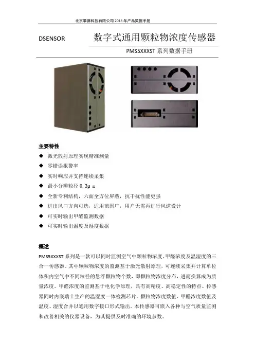
DSENSOR数字式通用颗粒物浓度传感器PMS5XXXST系列数据手册主要特性◆激光散射原理实现精准测量◆零错误报警率◆实时响应并支持连续采集◆最小分辨粒径0.3μm◆全新专利结构,六面全方位屏蔽,抗干扰性能更强◆进出风口方向可选,适用范围广,用户无需再进行风道设计◆可实时输出甲醛监测数据◆可实时输出温度及湿度数据概述PMS5XXXST系列是一款可以同时监测空气中颗粒物浓度、甲醛浓度及温湿度的三合一传感器。
其中颗粒物浓度的监测基于激光散射原理,可连续采集并计算单位体积内空气中不同粒径的悬浮颗粒物个数,即颗粒物浓度分布,进而换算成为质量浓度。
甲醛浓度的监测基于电化学原理,具有高精度、高稳定性的特点。
传感器同时内嵌瑞士生产的温湿度一体检测芯片。
颗粒物浓度数值、甲醛浓度数值及温度、湿度合并以通用数字接口形式输出。
本传感器可嵌入各种与空气质量监测和改善相关的仪器设备,为其提供及时准确的环境参数。
工作原理本传感器采用激光散射原理。
即令激光照射在空气中的悬浮颗粒物上产生散射,同时在某一特定角度收集散射光,得到散射光强随时间变化的曲线。
进而微处理器利用基于米氏(MIE)理论的算法,得出颗粒物的等效粒径及单位体积内不同粒径的颗粒物数量。
传感器各功能部分框图如图1所示图1 传感器功能框图甲醛监测功能采用电化学原理实现,加入数据处理算法,所获得的数据稳定、精确。
技术指标如表1所示表1 传感器技术指标数字接口定义PIN1图2 接口示意图输出结果1.颗粒物浓度:主要输出为单位体积内各浓度颗粒物质量以及个数,其中颗粒物个数的单位体积为0.1升,质量浓度单位为:微克/立方米(μg/m³)。
此外传感输出分为主动输出和被动输出两种状态。
传感器上电后默认状态为主动输出,即传感器主动向主机发送串行数据,时间间隔为200~800ms,空气中颗粒物浓度越高,时间间隔越短。
主动输出又分为两种模式:平稳模式和快速模式。
在空气中颗粒物浓度变化较小时,传感器输出为平稳模式,即每三次输出同样的一组数值,实际数据更新周期约为2s。
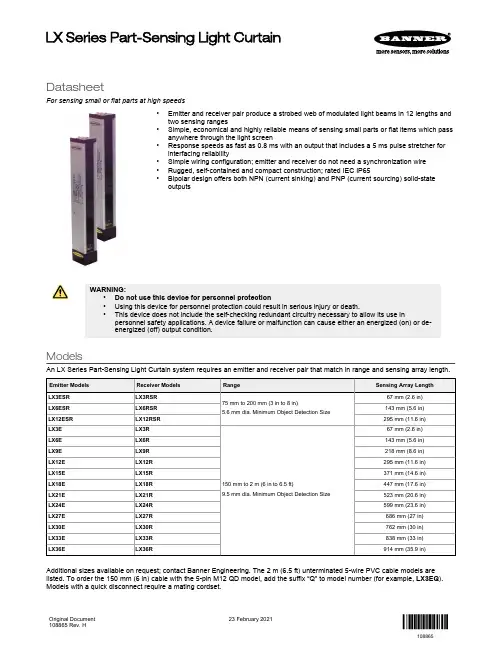
DatasheetFor sensing small or flat parts at high speeds•Emitter and receiver pair produce a strobed web of modulated light beams in 12 lengths and two sensing ranges•Simple, economical and highly reliable means of sensing small parts or flat items which pass anywhere through the light screen•Response speeds as fast as 0.8 ms with an output that includes a 5 ms pulse stretcher for interfacing reliability•Simple wiring configuration; emitter and receiver do not need a synchronization wire •Rugged, self-contained and compact construction; rated IEC IP65•Bipolar design offers both NPN (current sinking) and PNP (current sourcing) solid-stateoutputsWARNING:•Do not use this device for personnel protection•Using this device for personnel protection could result in serious injury or death.•This device does not include the self-checking redundant circuitry necessary to allow its use inpersonnel safety applications. A device failure or malfunction can cause either an energized (on) or de-energized (off) output condition.ModelsAn LX Series Part-Sensing Light Curtain system requires an emitter and receiver pair that match in range and sensing array length.Additional sizes available on request; contact Banner Engineering. The 2 m (6.5 ft) unterminated 5-wire PVC cable models are listed. To order the 150 mm (6 in) cable with the 5-pin M12 QD model, add the suffix “Q” to model number (for example, LX3EQ ).Models with a quick disconnect require a mating cordset.LX Series Part-Sensing Light CurtainOriginal Document 108865 Rev. H23 February 2021108865Theory of OperationThe LX Series light screen sensing system consists of two self-contained units: an emitter and a receiver of equal size and sensing range. The emitter has multiple infrared LEDs spaced at 9.5 mm (0.38 in) increments, and the receiver has corresponding photodiodes. The emitter sequentially fires each infrared LED. Multiple photodiodes in the receiver recognize each of the emitted pulses; the result is a “cross-hatched” optical pattern. Optical synchronization enables the receiver to recognize light from each of the emitter LEDs.The optical crosshatch pattern enables the LX system to detect targets of very small diameter, and extremely thin, flat objects—as thin as a piece of paper or an envelope. For small diameter objects, the sensing resolution is less effective at the exact center (see the minimum object detection size specification) of the sensing range and at the extreme edges of the pattern (close to the emitter and receiver faces); sensing should take place within the center 80 percent of the range, as shown.Figure 1. LX Series optical crosshatch patternSensing is most effective in thecenter 80% of the sensing rangeLX Series sensors are available in two ranges: short and standard. Short-range emitters and receivers may be located as close together as 75 mm (3 in), with a maximum separation of 200 mm (8 in). Standard-range sensors may be separated 150 mm to 2 m (6 in to 6.5 ft) apart. Both emitter and receiver must be either short-range or standard models, of the same length. Detection sensitivity varies somewhat, depending on the distance between the sensors and the position of the target object.For closer-range applications, the working range of any sensor pair can be reduced by connecting the sensor’s Select wire to 0 V DC to 2 V DC (see the sensing range specification).The receiver output interfaces directly with DC loads or circuits up to 30 V DC, and offers both sinking (NPN) and sourcing (PNP) output transistors. Outputs conduct whenever a beam is broken. A 5 millisecond pulse stretcher (OFF-delay) is included to improve interfacing reliability.Typical ApplicationsTypical applications for the LX Series include parts ejection verification and package detection on a conveyor.Installation and AlignmentReliable performance of the LX series light screen systems requires a simple alignment process. Mount the sensor in a location as free from vibration as possible.Sensors may be mounted using the accessory brackets (available separately) or using the T-slots in the sensor housings. After mechanical alignment is completed, the sensors can be wired and power applied.1.Loosely mount the emitter and receiver at their operating locations with their front panels opposite each other, and atapproximately the same level.2.Adjust the emitter position until the receiver detects alignment (the yellow LED turns OFF). For best alignment, position theemitter in the middle of the positions that cause a clear receiver condition.3.Tighten the bracket hardware.4.Position a pencil or similar object within the sensing area to verify that it can be reliably detected throughout the sensingarea. - Tel: + 1 888 373 6767P/N 108865 Rev. HWiring DiagramsFigure 2. Wiring for the integral cable modelsReduced 0–2 V DCNormal 5–30 V DC ReceiverEmitterFigure 3. Wiring for the quick disconnect modelsNormal 5–30 V DC ReceiverEmitter* Banner recommends connecting the shield wire to earth ground or DC common.** If there is no connection, the Normal Range will be used.SpecificationsSupply Voltage and Power10 V DC to 30 V DC (10% maximum ripple) at less than 1 watt each for emitter and receiver (exclusive of load)Supply Protection CircuitryProtected against reverse polarity and transient voltages Sensing RangeSee Wiring Diagrams on p. 3Output ConfigurationBipolar: One current sourcing (PNP) and one current sinking (NPN) open-collector transistor Output Rating125 mA maximum each outputOff-state leakage current: less than 5 microampsOutput saturation voltage (PNP output): < 1 V at 10 mA and < 1.5 V at 100 mA Output saturation voltage (NPN output): < 0.5 V at 10 mA and < 0.6 V at 100 mA Output Protection CircuitryProtected against false pulse on power-up and continuous overload or short circuit of outputsMinimum Object Detection Size (MODS)Smallest diameter rod that can be detected in sensing range:Short-Range: 5.6 mm (0.22 in)Standard-Range: 9.5 mm (0.38 in)Indicators Emitter:•LED1 (green)◦ON: Power ON, good sensor ◦OFF: Reduced Range ◦ON:Power ON, good sensor•LED2 (red)◦ON: Reduced range ◦OFF: Normal range ◦Flashing: Emitter hardware failureReceiver•LED1 (yellow)◦ON: Output conducting ◦OFF: Output not conducting•LED2 (bicolor green/red)◦Green: Normal range ◦Red: Reduced range ◦Flashing Red: Receiver hardware failureP/N 108865 Rev. H - Tel: + 1 888 373 67673Output Response TimeLX3: 0.8 ms ON-time; 6 ms OFF-time (5 ms OFF-delay)LX6: 1.6 ms ON-time; 7 ms OFF-time (5 ms OFF-delay)LX9: 2.4 ms ON-time; 7.5 ms OFF-time (5 ms OFF-delay)LX12: 3.2 ms ON-time; 8.5 ms OFF-time (5 ms OFF-delay)LX15: 4.0 ms ON-time; 9 ms OFF-time (5 ms OFF-delay)LX18: 4.8 ms ON-time; 10 ms OFF-time (5 ms OFF-delay)LX21: 5.6 ms ON-time; 11 ms OFF-time (5 ms OFF-delay)LX24: 6.4 ms ON-time; 11.5 ms OFF-time (5 ms OFF-delay)LX27: 7.2 ms ON-time; 12 ms OFF-time (5 ms OFF-delay)LX30: 8 ms ON-time; 13 ms OFF-time (5 ms OFF-delay)LX33: 8.8 ms ON-time; 14 ms OFF-time (5 ms OFF-delay)LX36: 9.6 ms ON-time; 15 ms OFF-time (5 ms OFF-delay)ConstructionAluminum housing, die cast zinc with black e-coat painted endcaps, acrylic lens window Connections2 meter (6.5 ft) 5-conductor (with drain) pvc-jacketed attached cable or a 150 mm (6 in) PVC cable with a 5-pin M12 male quick disconnect,depending on the model Application Notes1.The best sensing resolution occurs within the center 80% of the sensing range (Figure 1 on p. 2).2.Low-profile packages can be reliably detected.3.Outputs are active while the light screen is interrupted.4.For reliable detection, successive parts must be spaced up to the total of ON-time plus OFF-time apart. (that is, 12milliseconds for the LX12)Required Overcurrent ProtectionWARNING: Electrical connections must be made by qualified personnel in accordance with local and national electrical codes and regulations.Overcurrent protection is required to be provided by end product application per the supplied table.Overcurrent protection may be provided with external fusing or via Current Limiting, Class 2 Power Supply.Supply wiring leads < 24 AWG shall not be spliced.For additional product support, go to .Environmental Rating Meets IEC IP65Operating Conditions–20 °C to +70 °C (–4 °F to +158 °F)90% at +50 °C maximum relative humidity (non-condensing)CertificationsE71083Class 2 Power UL Environmental Rating: Type 1Dimensions - Tel: + 1 888 373 6767P/N 108865 Rev. HAccessoriesQuick-Disconnect (QD) CablesMounting BracketsSMBLX•End-cap brackets; set of 2•Zinc-plated cold rolled steel•Hardware included formounting brackets to sensorHole center spacing: A = 12.7Hole size: A = ø 4.3SMBLXR•Back-mount bracket forsecure one-end mounting•Zinc-plated cold rolled steel•Hardware included formounting bracket to sensorHole center spacing: A , B = 63.5, Ato B = 10.2Hole size: A , B = 5.2 x 11.6LX Series Lens ShieldsP/N 108865 Rev. H - Tel: + 1 888 373 67675Banner Engineering Corp. Limited WarrantyBanner Engineering Corp. warrants its products to be free from defects in material and workmanship for one year following the date of shipment. Banner Engineering Corp. will repair or replace, free of charge, any product of its manufacture which, at the time it is returned to the factory, is found to have been defective during the warranty period. This warranty does not cover damage or liability for misuse, abuse, or the improper application or installation of the Banner product.THIS LIMITED WARRANTY IS EXCLUSIVE AND IN LIEU OF ALL OTHER WARRANTIES WHETHER EXPRESS OR IMPLIED (INCLUDING, WITHOUT LIMITATION, ANY WARRANTY OF MERCHANTABILITY OR FITNESS FOR A PARTICULAR PURPOSE), AND WHETHER ARISING UNDER COURSE OF PERFORMANCE, COURSE OF DEALING OR TRADE USAGE.This Warranty is exclusive and limited to repair or, at the discretion of Banner Engineering Corp., replacement. IN NO EVENT SHALL BANNER ENGINEERING CORP. BE LIABLE TO BUYER OR ANY OTHER PERSON OR ENTITY FOR ANY EXTRA COSTS, EXPENSES, LOSSES, LOSS OF PROFITS, OR ANY INCIDENTAL, CONSEQUENTIAL OR SPECIAL DAMAGES RESULTING FROM ANY PRODUCT DEFECT OR FROM THE USE OR INABILITY TO USE THE PRODUCT, WHETHER ARISING IN CONTRACT OR WARRANTY, STATUTE, TORT, STRICT LIABILITY, NEGLIGENCE, OR OTHERWISE.Banner Engineering Corp. reserves the right to change, modify or improve the design of the product without assuming any obligations or liabilities relating to any product previously manufactured by Banner Engineering Corp. Any misuse, abuse, or improper application or installation of this product or use of the product for personal protection applications when the product is identified as not intended for such purposes will void the product warranty. Any modifications to this product without prior express approval by Banner Engineering Corp will void the product warranties. All specifications published in this document are subject to change; Banner reserves the right to modify product specifications or update documentation at any time. Specifications and product information in English supersede that which is provided in any other language. For the most recent version of any documentation, refer to:.For patent information, see /patents.© Banner Engineering Corp. All rights reserved。
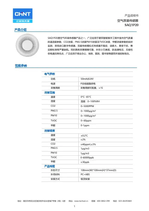
SAQ1P20产品介绍SAQ1P20是空气环境传感器产品之一,广泛应用于建筑智能楼宇工程中室内空气质量的温湿度参数、CO2浓度、PM2.5浓度PM10浓度及TVOC浓度、甲醛浓度参数的实时监测,采用进口数字传感器,克服传统模拟式传感器不稳定、误差大、易受干扰、需定期校准等严重缺陷。
同时具有采集精确可靠、外形小巧美观、防浪涌电压、无极性供电通讯等优点,广泛应用于商业办公、地铁、医院、图书馆等建筑环境控制场合。
性能参数电气参数功耗50mA@24V电源P总线链路供电采集周期采集周期可配置,≥1S测量范围温度0°C- 65°C湿度湿度:0~100%RHCO2 0~5000PPMPM2.5 0~1000μg/m³PM10 0~1000μg/m³TVOC 0~60ppm甲醛0-1ppm测量精度温度±0.2℃湿度±2%CO2 ±40ppm\±3%PM2.5 1μg/m3PM10 1μg/m3TVOC 0-60000ppb甲醛±30ppb产品规格外形尺寸108mm(W)*108mm(H)*37mm(D)外壳材料PC+ABS安装方式吸顶安装SAQ1P20操作说明设备上线时,点击中间圆形按钮(图中方框区域)。
即可读取到设备ID,使设备上线安装示意图接线/尺寸图注意事项⏹请按正确的接线标识图接线,不正确的接线可能会导致设备损坏⏹接线时,请切断电源,带电接线可能会造成电击危险⏹设备安装时应避免阳光直射,注意防潮、防尘、不能受雨淋⏹设备有故障或使用有疑问时,请与厂家技术联系装箱清单⏹设备*1/端子*2/合格证*1/说明书*1本文所含信息如有变更,不予另行通知。
本文保有未经通知即可变更与修改文本内容之权利。

甲醛模组(型号:ZE08-CH2O)使用说明书版本号:1.7实施日期:2020.04.17郑州炜盛电子科技有限公司Zhengzhou Winsen Electronic Technology Co.,Ltd声明本说明书版权属郑州炜盛电子科技有限公司(以下称本公司)所有,未经书面许可,本说明书任何部分不得复制、翻译、存储于数据库或检索系统内,也不可以电子、翻拍、录音等任何手段进行传播。
感谢您使用炜盛科技的系列产品。
为使您更好地使用本公司产品,减少因使用不当造成的产品故障,使用前请务必仔细阅读本说明书并按照所建议的使用方法进行使用。
如果您不依照本说明书使用或擅自去除、拆解、更换传感器内部组件,本公司不承担由此造成的任何损失。
您所购买产品的颜色、款式及尺寸以实物为准。
本公司秉承科技进步的理念,不断致力于产品改进和技术创新。
因此,本公司保留任何产品改进而不预先通知的权力。
使用本说明书时,请确认其属于有效版本。
同时,本公司鼓励使用者根据其使用情况,探讨本产品更优化的使用方法。
请妥善保管本说明书,以便在您日后需要时能及时查阅并获得帮助。
郑州炜盛电子科技有限公司产品描述电化学甲醛模组ZE08-CH 2OZE 08-CH 2O型电化学甲醛模组是一个通用型、小型化模组。
利用电化学原理对空气中存在的CH 2O进行探测,具有良好的选择性,稳定性。
内置温度传感器,可进行温度补偿;同时具有数字输出与模拟电压输出,方便使用。
ZE 08-CH 2O是将成熟的电化学检测技术与精良的电路设计紧密结合,设计制造出的通用型气体模组。
模组特点高灵敏度、高分辨率、低功耗、使用寿命长提供UART 、模拟电压信号等多种输出方式高稳定性、优秀的抗干扰能力、温度补偿、卓越的线性输出主要应用便携式仪表、空气质量监测设备、空气净化机、新风换气系统、空调、智能家居设备等场所。
技术指标表1图1:模组结构图产品型号ZE 08-CH 2O 检测气体甲醛干扰气体酒精,一氧化碳等气体输出数据DAC(0.4~2V 电压信号对应浓度:0~满量程)UART 输出(3V TTL 电平)工作电压 3.7V~5.5V 预热时间≤3分钟响应时间≤60秒恢复时间≤60秒量程0~5ppm 分辨率≤0.01ppm 工作温度-20℃~50℃工作湿度15%RH-90%RH(无凝结)存储温度0~25℃使用寿命5年(空气中18℃~25℃)管脚定义表2管脚名称管脚说明Pin1预留Pin2DAC(0.4~2V,对应0-满量程)Pin3GNDPin4Vin(电压输入 3.7V~5.5V)Pin5UART(RXD)0~3.3V 数据输入Pin6UART(TXD)0~3.3V 数据输出Pin7预留图2:模组引脚图通讯协议1通用设置表3波特率9600数据位8位停止位1位校验位无2通讯命令通信分为主动上传式和问答式,出厂默认主动上传,每间隔1S发送一次浓度值。
Datasheet SGP30Sensirion Gas Platform▪ Multi-pixel gas sensor for indoor air quality applications ▪ Outstanding long-term stability▪ I 2C interface with TVOC and CO 2eq output signals ▪ Very small 6-pin DFN package: 2.45 x 2.45 x 0.9 mm 3 ▪ Low power consumption: 48 mA at 1.8V ▪ Tape and reel packaged, reflow solderableBlock DiagramFigure 1 Functional block diagram of the SGP30.Product SummaryThe SGP30 is a digital multi-pixel gas sensor designed for easy integration into air purifier, demand-controlled ventilation, and IoT applications. Sensirion’s CMOSens ® technology offers a complete sensor system on a single chip featuring a digital I 2C interface, a temperature controlled micro hotplate, and two preprocessed indoor air quality signals. As the first metal-oxide gas sensor featuring multiple sensing elements on one chip, the SGP30 provides more detailed information about the air quality.The sensing element features an unmatched robustness against contaminating gases present in real-world applications enabling a unique long-term stability and low drift. The very small 2.45 x 2.45 x 0.9 mm 3 DFN package enables applications in limited spaces. Sensirion’s state-of-the-art production process guarantees high reproducibility and reliability. Tape and reel packaging, together with suitability for standard SMD assembly processes make the SGP30 predestined for high-volume applications.1Sensor Performance 1.1Gas Sensing PerformanceAccuracy ethanol signalFigure 2Typical and maximum accuracy tolerance in % of measured value at 25°C, 50% RH and typical VDD. The sensors have been operated for at least 24h before the characterization. Accuracy H2 signalFigure 3Typical and maximum accuracy tolerance in % of measured value at 25°C, 50% RH and typical VDD. The sensors have been operated for at least 60h before the characterization.1 Exposure to ethanol and H2 concentrations up to 1000 ppm have been tested. For applications requiring the measurement of higher gas concentrations please contact Sensirion.2 ppm: parts per million. 1 ppm = 1000 ppb (parts per billion)3 90% of the sensors will be within the typical accuracy tolerance, >99% are within the maximum tolerance.4 The long-term drift is stated as change of accuracy per year of operation.5 Test conditions: operation in 250 ppm Decamethylcyclopentasiloxane (D5) for 200h simulating 10 years of operation in an indoor environment.Long-term drift Ethanol signalmeasuredLong-term drift H2 signalFigure 5Typical and maximum long-term drift in % of measuredvalue at 25°C, 50% RH and typical VDD. The sensors have beenoperated for at least 60h before the first characterization.Figure 6 Simplified version of the functional block diagram (compare Figure 1) showing the signalpaths of the SGP30.1.3Recommended Operating ConditionsThe sensor shows best performance when operated within recommended normal temperature and humidity range of5 – 55 °C and 4 –20 g/m3, respectively. Long-term exposure (operated and not operated) to conditions outside therecommended range, especially at high humidity, may affect the sensor performance. Prolonged exposure to extreme conditions may accelerate aging. To ensure stable operation of the gas sensor, the conditions described in the document SGP Handling and Assembly Instructions regarding exposure to exceptionally high concentrations of some organic or inorganic compounds have to be met, particularly during operation. Please also refer to the Design-in Guide for optimal integration of the SGP30.2Electrical Specifications6 A 20% higher current is drawn during 5ms on V DDH after entering the measurement mode.Table 5 Absolute minimum and maximum ratings.Please contact Sensirion for storage, handling and assembly instructions.7 If VDD and VDDH are not shorted, it is required that VDD is always powered when VDDH is powered. Otherwise, the sensor might be damaged.85 Timing Specifications5.1 Sensor System TimingsThe timings refer to the power up and reset of the ASIC part and do not reflect the usefulness of the readings.Parameter Symbol ConditionMin. Typ. Max. Unit Comments Power-up time t PU After hard reset, V DD ≥V POR - 0.4 0.6 ms - Soft reset timet SRAfter soft reset-0.40.6ms-Table 6 System timing specifications.5.2 Communication TimingsParameter Symbol Conditions Min. Typ. Max. Units Comments SCL clock frequencyf SCL-- 400 kHz - Hold time (repeated) START conditiont HD;STA After this period, the first clock pulse is generated 0.6 --µs-LOW period of the SCL clock t LOW - 1.3 - - µs - HIGH period of the SCL clockt HIGH- 0.6 - - µs - Set-up time for a repeated START condition t SU;STA - 0.6 - - µs - SDA hold time t HD;DAT - 0 - - ns - SDA set-up time t SU;DAT - 100 - - ns - SCL/SDA rise time t R - - - 300 ns - SCL/SDA fall time t F - - - 300 ns - SDA valid timet VD;DAT - - - 0.9 µs - Set-up time for STOP condition t SU;STO - 0.6 - - µs - Capacitive load on bus lineC B-400pF-Table 7 Communication timing specifications.Figure 8 Timing diagram for digital input/output pads. SDA directions are seen from the sensor. Bold SDA lines are controlled by the sensor; plain SDA lines are controlled by the micro-controller. Note that SDA valid read time is triggered by falling edge of preceding toggle.SCL70% 30%t LOW1/f SCL t HIGHt Rt FSDA70% 30%t SU;DATt HD;DATDATA INt RSDA70% 30% DATA OUTt VD;DATt F6Operation and CommunicationThe SGP30 supports I2C fast mode. For detailed information on the I2C protocol, refer to NXP I2C-bus specification8. All SGP30 commands and data are mapped to a 16-bit address space. Additionally, data and commands are protected with a CRC checksum to increase the communication reliability. The 16-bit commands that are sent to the sensor already include a 3-bit CRC checksum. Data sent from and received by the sensor is always succeeded by an 8-bit CRC.In write direction it is mandatory to transmit the checksum, since the SGP30 only accepts data if it is followed by the correct checksum. In read direction it is up to the master to decide if it wants to read and process the checksum.The I2C master can abort the read transfer with a XCK followed by a STOP condition after any data byte if it is not interested in subsequent data, e.g. the CRC byte or following data bytes, in order to save time. Note that the data cannot be read more than once, and access to data beyond the specified amount will return a pattern of 1s.6.3Measurement CommandsThe available measurement commands of the SGP30 are listed in Table 10.Air Quality SignalsThe SGP30 uses a dynamic baseline compensation algorithm and on-chip calibration parameters to provide two complementary air quality signals. Based on the sensor signals a total VOC signal (TVOC) and a CO 2 equivalent signal (CO 2eq) are calculated. Sending an “Init_air_quality” command starts the air quality measurement. After the “Init_air_quality” command, a “Measure_air_quality” command has to be se nt in regular intervals of 1s to ensure proper operation of the dynamic baseline compensation algorithm. The sensor responds with 2 data bytes (MSB first) and 1 CRC byte for each of the two preprocessed air quality signals in the order CO 2eq (ppm) and TVOC (ppb). For the first 15s after the “Init_air_quality” command the sensor is in an initialization phase during which a “Measure_air_quality” command returns fixed values of 400 ppm CO 2eq and 0 ppb TVOC.The SGP30 also provides the possibility to read and write the baseline values of the baseline correction algorithm. This feature is used to save the baseline in regular intervals on an external non-volatile memory and restore it after a new power-up or soft reset of the sensor. The command “Get_baseline” ret urns the baseline values for the two air quality signals. The sensor responds with 2 data bytes (MSB first) and 1 CRC byte for each of the two values in the order CO 2eq and TVOC. These two values should be stored on an external memory. After a power-up or soft reset, the baseline of the baseline correction algorithm can be restored by sending first an “Init_air_quality” command followed by a “Set_baseline” command with the two baseline values as parameters in the order as (TVOC, CO 2eq). An example implementation of a generic driver for the baseline algorithm can be found in the document SGP30_driver_integration_guide .A new “Init_air_quality” command has to be sent after every power -up or soft reset.Sensor Raw SignalsThe command “Measure_raw_signals” is i ntended for part verification and testing purposes. It returns the sensor raw signals which are used as inputs for the on-chip calibration and baseline compensation algorithms as shown in Figure 6. The command performs a measurement to which the sensor responds with 2 data bytes (MSB first) and 1 CRC byte (see Figure 9) for 2 sensor raw signals in the order H2_signal (s out_H2) and Ethanol_signal (s out_EthOH ). Both signals can be used to calculate gas concentrations c relative to a reference concentration c ref byln (c c ref ⁄)=s ref −s outawith a = 512, s ref the H2_signal or Ethanol_signal output at the reference concentration, and s out = s out_H2 or s out = s out_EthOH .Humidity CompensationThe SGP30 features an on-chip humidity compensation for the air quality signals (CO 2eq and TVOC) and sensor raw signals (H2-signal and Ethanol_signal). To use the on-chip humidity compensation an absolute humidity value from an external humidity sensor like the SHTxx is required. Using the “Set_humidity” comm and, a new humidity value can be written to the SGP30 by sending 2 data bytes (MSB first) and 1 CRC byte. The 2 data bytes represent humidity values as a fixed-point 8.8bit number with a minimum value of 0x0001 (=1/256 g/m 3) and a maximum value of 0xFFFF (255 g/m 3 + 255/256 g/m 3). For instance, sending a value of 0x0F80 corresponds to a humidity value of 16.50 g/m 3 (16 g/m 3 + 128/256 g/m 3).After setting a new humidity value, this value will be used by the on-chip humidity compensation algorithm until a new humidity value is set using the “Set_humidity” command. Restarting the sensor (power-on or soft reset) or sending a value of 0x0000 (= 0 g/m 3) sets the humidity value used for compensation to its default value (0x0B92 = 11.57 g/m 3) until a new humidity value is sent. Sending a humidity value of 0x0000 can therefore be used to turn off the humidity compensation.Feature SetThe SGP30 features a versioning system for the available set of measurement commands and on-chip algorithms. This so called feature se t version number can be read out by sending a “Get_feature_set_version ” command. The sensor responds with 2 data bytes (MSB first) and 1 CRC byte (see Table 9). This feature set version number is used to refer to a corresponding set of available measurement commands as listed in Table 10.Table 9 Structure of the SGP feature set number. Please note that the last 5 bits of the product version (bits 12-16 of the LSB) are subject to change. This is used to track new features added to the SGP multi-pixel platform.Measure TestThe command “Measure_test” which is included for integration and production line testing runs an on-chip self-test. In case of a successful self-test the sensor returns the fixed data pattern 0xD400 (with correct CRC).9 The «Measure_Test» command is intended for production line testing and verification only. It should not be used after having issued an “Init_air_quality” command. For the duration of the «Measure_Test» command, the sensor is operated in measurement mode with a supply current as specified in Table 3. After the command, the sensor is in sleep mode.Table 13 I2C CRC properties.6.7Communication Data SequencesFigure 10 Laser marking on SGP30. The pin-1 location is indicated by the keyhole pattern in the light-colored central area. The bottom line contains a 4-digit alphanumeric tracking code8.3Package OutlineFigure 12 Recommended landing pattern.9Tape & Reel Package11Important Notices11.1Warning, Personal InjuryDo not use this product as safety or emergency stop devices or in any other application where failure of the product could result in personal injury. Do not use this product for applications other than its intended and authorized use. Before installing, handling, using or servicing this product, please consult the data sheet and application notes. Failure to comply with these instructions could result in death or serious injury. If the Buyer shall purchase or use SENSIRION products for any unintended or unauthorized application, Buyer shall defend, indemnify and hold harmless SENSIRION and its officers, employees, subsidiaries, affiliates and distributors against all claims, costs, damages and expenses, and reasonable attorney fees arising out of, directly or indirectly, any claim of personal injury or death associated with such unintended or unauthorized use, even if SENSIRION shall be allegedly negligent with respect to the design or the manufacture of the product.11.2ESD PrecautionsThe inherent design of this component causes it to be sensitive to electrostatic discharge (ESD). To prevent ESD-induced damage and/or degradation, take customary and statutory ESD precautions when handling this product.See application note “ESD, Latchup and EMC” for more information.11.3WarrantySENSIRION warrants solely to the original purchaser of this product for a period of 12 months (one year) from the date of delivery that this product shall be of the quality, material and workmanship defined in SENSIRION’s published specifications of the product. Within such period, if proven to be defective, SENSIRION shall repair and/or replace this product, in SENSIRION’s discretion, free of charge to the Buyer, provided that:∙notice in writing describing the defects shall be given to SENSIRION within fourteen (14) days after their appearance;∙such defects shall be fou nd, to SENSIRION’s reasonable satisfaction, to have arisen from SENSIRION’s faulty design, material, or workmanship;∙the defective product shall be returned to SENSIRION’s factory at the Buyer’s expense; and∙the warranty period for any repaired or replaced product shall be limited to the unexpired portion of the original period.This warranty does not apply to any equipment which has not been installed and used within the specifications recommended by SENSIRION for the intended and proper use of the equipment. EXCEPT FOR THE WARRANTIES EXPRESSLY SET FORTH HEREIN, SENSIRION MAKES NO WARRANTIES, EITHER EXPRESS OR IMPLIED, WITH RESPECT TO THE PRODUCT. ANY AND ALL WARRANTIES, INCLUDING WITHOUT LIMITATION, WARRANTIES OF MERCHANTABILITY OR FITNESS FOR A PARTICULAR PURPOSE, ARE EXPRESSLY EXCLUDED AND DECLINED. SENSIRION is only liable for defects of this product arising under the conditions of operation provided for in the data sheet and proper use of the goods. SENSIRION explicitly disclaims all warranties, express or implied, for any period during which the goods are operated or stored not in accordance with the technical specifications.SENSIRION does not assume any liability arising out of any application or use of any product or circuit and specifically disclaims any and all liability, including without limitation consequential or incidental damages. All operating parameters, including without limitation recommended parameters, must be validated for each customer’s applications by customer’s technical experts. R ecommended parameters can and do vary in different applications. SENSIRION reserves the right, without further notice, (i) to change the product specifications and/or the information in this document and (ii) to improve reliability, functions and design of this product.Copyright© 2017 by SENSIRION.CMOSens® is a trademark of Sensirion.All rights reserved.12Headquarters and SubsidiariesSensirion AG Laubisruetistr. 50CH-8712 Staefa ZH Switzerlandphone: +41 44 306 40 00 fax: +41 44 306 40 30 ****************** Sensirion Inc., USAphone: +1 312 690 5858*********************Sensirion Korea Co. Ltd.phone: +82 31 337 7700~3*********************www.sensirion.co.kr Sensirion Japan Co. Ltd.phone: +81 3 3444 4940*********************www.sensirion.co.jpSensirion China Co. Ltd.phone: +86 755 8252 1501*********************Sensirion Taiwan Co. Ltdphone: +886 3 5506701****************** To find your local representative, please visit /distributors。
Datasheet•Advanced one-piece photoelectric sensors with outstanding optical performance and extremely rugged design•Operate from 90 to 250 V ac (50/60 Hz)•SPDT electromechanical relay output for economical, high-capacity switching and immunity to electrical noise•Multiple sensing modes include: opposed, diffuse, retroreflective, and convergent, plus glass and plastic fiber optic models •Switchable light/dark operate•Versatile plug-in modules available for output timing logic and/or signal strength display •Highly visible Power, Signal (AID ™ System 1), and Output indicator LEDs•Choice of prewired 2 m (6.5 ft) or 9 m (30 ft) unterminated cable or Mini-style quick-disconnect fitting•Versatile mountingoptions•Designed to withstand 1200 psi washdown; exceeds its NEMA 6P and IEC IP67 ratingWARNING: Not To Be Used for Personnel ProtectionNever use this device as a sensing device for personnel protection. Doing so could lead to serious injury or death. This device does not include the self-checking redundant circuitry necessary to allow its use in personnel safety applications. A sensor failure or malfunction can cause either an energized or de-energized sensor output condition.To order the 9 m (30 ft) cable models, add the suffix "W/30" to the cabled model number. (For example: Q452E W/30.) Models with a quick disconnect (QD) connector require a mating cable.Q45VR2 Series SensorsOriginal Document 36339 Rev. H30 January 201736339To order the 9 m (30 ft) cable models, add the suffix "W/30" to the cabled model number. (For example: Q45VR2LV W/30.) Models with a quick disconnect (QD) connector require a mating cable. - Tel: +1-763-544-3164P/N 36339 Rev. HP/N 36339 Rev. H - Tel: +1-763-544-31643To order the 9 m (30 ft) cable models, add the suffix "W/30" to the cabled model number. (For example: Q45VR2CV W/30.) Models with a quick disconnect (QD) connector require a mating cable. - Tel: +1-763-544-3164P/N 36339 Rev. HP/N 36339 Rev. H - Tel: +1-763-544-31645To order the 9 m (30 ft) cable models, add the suffix "W/30" to the cabled model number. (For example: Q45VR2FP W/30.) Models with a quick disconnect (QD) connector require a mating cable.OverviewStatus indicator LEDs for power, signal, and output are clearly visible beneath a raised dome in the sensor’s transparent o-ring-sealed polycarbonate cover. Also located beneath the sensor’s o-ring-sealed cover are controls for light/dark operate selection and the sensitivity adjustment.•The power indicator (green) lights when power is applied to the sensor.•The signal indicator (red) lights when the sensor sees its modulated light source and pulses at a rate proportional to thestrength of the received light signal; this is the AID ™ Alignment Indicating Device 2.•The output indicator (amber) lights when the sensor’s output is conducting. This indicator is especially useful when a timinglogic module is used and signal and output conditions are not concurrent.1.Sensitivity adjustment2.LEDs•Green LED: Power on indicator •Red LED: Signal indicator•Amber LED: Output status indicator3.Optional LED signal strength display4.Optional timing adjustment5.Optional timing adjustment6.Light/dark operate switch - Tel: +1-763-544-3164P/N 36339 Rev. HSpecificationsSupply Voltage and Current90 to 250 V ac (50/60 Hz)Average current 20 mAPeak current 500 mA at 120 V ac, 750 mA at 250 V ac Supply Protection CircuitryProtected against transient voltagesOutput ConfigurationSPDT (Single-Pole Double-Throw) electromechanical relay output. All models except emitters.Output RatingMax. switching power (resistive load): 150 W, 600 VA Max. switching voltage (resistive load): 250 V ac, 30 V dc Max. switching current (resistive load): 5 A at 250 V ac Min. voltage and current: 5 V dc, 0.1 mAMechanical life of relay: 10,000,000 operationsElectrical life of relay at full resistive load: 100,000 operations Output Protection CircuitryProtected against false pulse on power-up Output Response Time15 milliseconds ON and OFFNote: 100 millisecond delay on power-up. Output is de-energized during this timeRequired OvercurrentProtectionWARNING: Electrical connections must be made by qualified personnel in accordance with local and national electrical codes and regulations.Overcurrent protection is required to be provided by end product application per the supplied table.Overcurrent protection may be provided with external fusing or via Current Limiting, Class 2 Power Supply.Supply wiring leads < 24 AWG shall not be spliced.For additional product support, go to .RepeatabilityOpposed mode: 0.25 millisecondsAll other sensing modes: 0.5 millisecondsResponse time and repeatability specifications are independent of signal strength.AdjustmentsLight/Dark Operate select switch and multi-turn Sensitivity control (allows precise sensitivity setting – turn clockwise to increase gain).Optional logic and logic/display modules have adjustable timing functions.IndicatorsIndicator LEDs are clearly visible beneath a raised transparent Lexan ® dome on top of the sensorPower (green) LED lights when 90 to 250 V ac power is appliedSignal (red) AID ™ System LED lights when the sensor sees its modulated light source and pulses at a rate proportional to the strength of the received light signalLoad (amber) LED lights whenever the output relay is energized Optional 7-element LED signal strength display modules ConstructionMolded reinforced thermoplastic polyester housing, o-ring-sealed transparent polycarbonate cover, molded acrylic lenses, and stainless steel hardware. Q45s are designed to withstand 1200 psi washdown.The base of cabled models has a 1/2-inch NPS integral internal conduit thread.ConnectionsPVC-jacketed 2-wire (emitters) or 5-wire (all others) 2 m (6.5 ft) or 9 m (30 ft)unterminated cables, or 3-pin (emitters) or 5-pin (all others) Mini-style quick-disconnect (QD) fittings are available (“Q” - suffix models).QD cables are ordered separately.Application NotesTransient suppression is recommended for contacts switching inductive loads.Optional output timing modules are available.Environmental RatingNEMA 6P, IEC IP67Operating ConditionsTemperature: −40 °C to +70 °C (−40 °F to +158 °F)Maximum relative humidity: 90% at 50 °C (non-condensing)CertificationsP/N 36339 Rev. H - Tel: +1-763-544-31647Dimensions2m (6.5') CableTransparent Cover (Gasketed)External thread (M30 x 1.5)hex nut supplied - Tel: +1-763-544-3164P/N 36339 Rev. HWiring DiagramsNC C NONC C NObrown blue90–250 V acAccessoriesP/N 36339 Rev. H - Tel: +1-763-544-31649Retroreflective TargetsBanner offers a wide selection of high-quality retroreflective targets. See for completeinformation.Note: Polarized sensors require corner cube typeretroreflective targets. Non-polarized sensors may use any retroreflective target.Output Timing Logic and Signal Strength Display ModulesQ45 sensors easily accept the addition of output timing logic and signal strength display functions. Display modules have a seven-element display that gives a more precise indication of excess gain than does the AID ™ system LED that is standard on Q45 sensors. The modules listed below may be used with all Q45VR2 sensors. Refer to the module's datasheet for more - Tel: +1-763-544-3164P/N 36339 Rev. HQ45VR2 Series SensorsBanner Engineering Corp. Limited WarrantyBanner Engineering Corp. warrants its products to be free from defects in material and workmanship for one year following the date of shipment. Banner Engineering Corp. will repair or replace, free of charge, any product of its manufacture which, at the time it is returned to the factory, is found to have been defective during the warranty period. This warranty does not cover damage or liability for misuse, abuse, or the improper application or installation of the Banner product.THIS LIMITED WARRANTY IS EXCLUSIVE AND IN LIEU OF ALL OTHER WARRANTIES WHETHER EXPRESS OR IMPLIED (INCLUDING, WITHOUT LIMITATION, ANY WARRANTY OF MERCHANTABILITY OR FITNESS FOR A PARTICULAR PURPOSE), AND WHETHER ARISING UNDER COURSE OF PERFORMANCE, COURSE OF DEALING OR TRADE USAGE.This Warranty is exclusive and limited to repair or, at the discretion of Banner Engineering Corp., replacement. IN NO EVENT SHALL BANNER ENGINEERING CORP. BE LIABLE TO BUYER OR ANY OTHER PERSON OR ENTITY FOR ANY EXTRA COSTS, EXPENSES, LOSSES, LOSS OF PROFITS, OR ANY INCIDENTAL, CONSEQUENTIAL OR SPECIAL DAMAGES RESULTING FROM ANY PRODUCT DEFECT OR FROM THE USE OR INABILITY TO USE THE PRODUCT, WHETHER ARISING IN CONTRACT OR WARRANTY, STATUTE, TORT, STRICT LIABILITY, NEGLIGENCE, OR OTHERWISE. Banner Engineering Corp. reserves the right to change, modify or improve the design of the product without assuming any obligations or liabilities relating to any product previously manufactured by Banner Engineering Corp. Any misuse, abuse, or improper application or installation of this product or use of the product for personal protection applications when the product is identified as not intended for such purposes will void the product warranty. Any modifications to this product without prior express approval by Banner Engineering Corp will void the product warranties. All specifications published in this document are subject to change; Banner reserves the right to modify product specifications or update documentation at any time. Specifications and product information in English supersede that which is provided in any other language. For the most recent version of any documentation, refer to:.© Banner Engineering Corp. All rights reserved。
Datasheet•Fast, easy-to-use TEACH-Mode programming; no potentiometer adjustments •Selectable dual NPN or PNP outputs via DIP switch•Access to bank of 8 DIP switches through sealed cover for superior user functionality •Rugged encapsulated design for harsh environments•Unique housing design allows for multiple mounting configurations•Choose models with integral unterminated 2 m (6.5 ft) or 9 m (30 ft) cable, or with Mini-style or M12/Euro-style quick-disconnect connection•Wide operating range of −20 °C to +70 °C (−4 °F to +158 °F)•Temperature compensationWARNING: Not To Be Used for Personnel ProtectionNever use this device as a sensing device for personnel protection. Doing so could lead to serious injury or death. This device does not include the self-checking redundant circuitry necessary to allow its use inpersonnel safety applications. A sensor failure or malfunction can cause either an energized or de-energized sensor output condition.Principles of OperationUltrasonic sensors emit one or multiple pulses of ultrasonic energy, which travel through the air at the speed of sound. A portion of this energy reflects off the target and travels back to the sensor. The sensor measures the total time required for the energy to reach the target and return to the sensor. The distance to the object is then calculated using the following formula: D = ct ÷ 2D = distance from the sensor to the target c = speed of sound in airt = transit time for the ultrasonic pulseTo improve accuracy, an ultrasonic sensor may average the results of several pulses before outputting a new value.Temperature EffectsThe speed of sound is dependent upon the composition, pressure and temperature of the gas in which it is traveling. For most ultrasonic applications, the composition and pressure of the gas are relatively fixed, while the temperature may fluctuate.In air, the speed of sound varies with temperature according to the following approximation:In metric units:C m/s = 20 √273 + T C In English units:ft/s = 49 √460 + T F CC m/s = speed of sound in meters per second C ft/s = speed of sound in feet per second T C = temperature in °C T F = temperature in °F In metric units:C m/s = 20 √273 + T C In English units:ft/s = 49 √460 + T F CC m/s = speed of sound in meters per second C ft/s = speed of sound in feet per second T C = temperature in °CT F = temperature in °FThe speed of sound changes roughly 1% per 6° C (10° F). QT50U series ultrasonic sensors have temperature compensationavailable, via the 8-pin DIP switch. Temperature compensation will reduce the error due to temperature by about 90%.suffix w/30 to the model number of a cabled sensor (for example, QT50UDB w/30). A model with a QD connector requires a mating cable. Information about analog-output models is available on Banner Engineering website .U-GAGE ® QT50UDB Series Sensors with Dual-Discrete OutputsOriginal Document 110112 Rev. D14 September 2018110112Note: If the sensor is measuring across a temperature gradient, the compensation will be less effective. ConfigurationThe QT50U features an 8-pin DIP switch bankfor user setup. The DIP switches are locatedbehind the access cover on the back of thesensor as shown. A spanner tool is includedwith each sensor for removing the cover.* Factory default settingsDIP Switch Selectable FunctionsCAUTION:•Electrostatic Discharge (ESD) Sensitive Device•ESD can damage the device. Damage from inappropriate handling is not covered by warranty.•To avoid damage to the sensor, observe proper ESD precautions (grounding) while adjusting the DIP switches.Switch 1: Output Mode SelectON = Both outputs set to PNP (current sourcing)OFF = Both outputs set to NPN (current sinking)This switch configures the sensor internally to use either the PNP or NPN output configuration.Switch 2: High/Low Level ControlON = High/Low (fill level control)OFF = ON/OFF (window)This switch determines whether the sensor is in fill level control mode or normal ON/OFF mode. The fill level control is shown. When switch 2 is ON, the switch 3 setting will determine whether the sensor is set up for pump-in or pump-out operation. - Tel: +1-763-544-3164P/N 110112 Rev. DIn ON/OFF mode, the sensor is either ON or OFF when the target is within the window limits and opposite when outside of thewindow limit.Pump-In Application (using Normally Open Output)Pump-Out Application(using Normally Closed Output)The HIGH/LOW mode (switch #2 ON) provides the switching logic required for fill-level, web tensioning control, and similarapplications. In the HIGH/LOW mode, the output energizes when the target reaches the first sensing window limit, and stays energized until the target moves to the second limit. The output then de-energizes at the second limit and does not re-energize until the target moves, again, to the first limit.Switch 3: ON/OFF ModeON = normally open (output is energized when the target is within window)OFF = normally closed (output is energized when the target is outside window)Switch 4: Teach/Transmit Enable ControlON = Gray (or yellow) wire configured for remote teachOFF = Gray (or yellow) wire configured for transmit disable. High (5 to 30 V dc or open): Transmit Enabled (Power LED solid Green) or Low (0 to 2 V dc): Transmit Disabled (Power LED flashes at 2 Hz).When switch 4 is ON, the gray or yellow wire is used to teach the sensor’s window limits. When switch 4 is OFF, the gray or yellow wire is used to enable and disable the sensor’s transmit burst. This function may be used when multiple sensors are operating in close proximity and may be vulnerable to cross-talk interference. A PLC can be used to enable the sensors one at a time to avoid cross-talk.When disabled, the sensor outputs will react as if no target is being sensed.Switches 5-6: Response Speed AdjustmentThe speed of the output response is set using DIP-switch positions 5 and 6. There are four values for response speed, which relate to the number of sensing cycles over which the output value is averaged.Switch 7: Temperature CompensationON = Temperature compensation is enabled OFF = Temperature compensation is disabledChanges in air temperature affect the speed of sound, which in turn affects the distance reading measured by the sensor. Anincrease in air temperature shifts both sensing window limits closer to the sensor. Conversely, a decrease in air temperature shifts both limits farther away from the sensor. This shift is approximately 3.5% of the limit distance for a 20 °C change in temperature.With temperature compensation enabled (Switch 7 ON), the sensor will maintain the window limits to within 1.8% over the −20 °C to +70 °C (−4 °F to +158 °F) range.Note:•If temperature compensation is enabled, exposure to direct sunlight can affect the sensor’s ability to accurately compensate for changes in temperature.•With temperature compensation enabled, the temperature warmup drift upon power-up is less than 0.8% of the sensing distance. After 15 minutes, the apparent switchpoint will be within 0.5% of the actual position. After 30 minutes, the apparent switchpoint will be within 0.3% of the actual position.Switch 8: Factory CalibrationON = Factory calibration onlyP/N 110112 Rev. D - Tel: +1-763-544-31643OFF = Normal operationStatus IndicatorsFigure 3. Sensor Features1 - Output 1 button2 - Output 2 buttonOUTPUT 1 - Output 1 Indicator POWER - Sensor power indicatorSIGNAL - Target signal strength indicator OUTPUT 2 - Output 2 indicatorSensor ProgrammingThree TEACH methods may be used to program the sensor:•Teach individual minimum and maximum limits,•Use the Auto-Window feature to center a sensing window around the taught position, or•Simultaneously use Auto-Window and position a threshold for background suppression at the taught position.The sensor may be programmed either via its two push buttons, or via a remote switch. Remote programming also may be used to disable the push buttons, preventing unauthorized personnel from adjusting the programming settings. To access this feature,connect the gray wire of the sensor to 0–2 V dc, with a remote programming switch between the sensor and the voltage.Note: The impedance of the Remote Teach input is 12 kΩ.Programming is accomplished by following the sequence of input pulses. The duration of each pulse (corresponding to a push button “click”), and the period between multiple pulses, are defined as 0.04 seconds < T < 0.8 secondsnormally closed mode, the outputs will be ON. - Tel: +1-763-544-3164P/N 110112 Rev. DTeaching Minimum and Maximum LimitsMinimum MaximumMinimum Maximum Normally Closed OutputNormally Open OutputFigure 4. Teaching independent minimum and maximum limitsThe outputs are independent. To readjust minimum ormaximum limits for either output, follow the teach procedure for that output only.Repeat the teach procedure for the other output, if used.Push Button Method1. Enter Programming Mode2. Teaching the First Limit3. Teaching the Second LimitRemote Line Method (0.04 s < T < 0.8 s)1. Enter Programming Mode2. Teaching the First Limit3. Teaching the Second LimitP/N 110112 Rev. D - Tel: +1-763-544-31645Teaching Limits Using the Auto-Window FeatureTaught PositionNormally Closed OutputNormally Open OutputFigure 5. Using the Auto-Window feature for programming each outputTeaching the same limit twice for the same output automatically centers a 200 mm window on the taught position.The outputs are independent. To readjust a midpoint for either output, follow the teach procedure for that output only. Repeat theteach procedure for the other output, if used.Taught Position Sensor Output ONSensor Output OFFFigure 6. An application for Auto-Window feature (retroreflective mode)Push Button Method1. Enter Programming Mode2. Teaching the Limit3. Re-teaching the Limit - Tel: +1-763-544-3164P/N 110112 Rev. DRemote Line Method (0.04 s < T < 0.8 s)1. Enter Programming Mode2. Teaching the Limit3. Re-teaching the LimitSimultaneous Auto-Window/Background SuppressionOutput 1Output 2 Figure 7. Using simultaneous auto-window/background suppression (normallyopen illustrated)Output 1: Auto-Window (automatically centers a 200 mm window on taught position)Output 2: Background Suppression (sensor ignores objects beyond the taught position)Taught position is identical for both outputs.To adjust the Background Suppression limit (different from the limit for Output 1), teach a new limit to Output 2 using the Auto-Window procedure (seeTeaching Limits Using the Auto-Window Feature on page 6. Output 2 remains in Background Suppression mode until it is taught new min/max limits.Push Button Method1. Enter Programming Mode2. Teaching Limits to Both Outputs SimultaneouslyP/N 110112 Rev. D - Tel: +1-763-544-31647Remote Line Method (0.04 s < T < 0.8 s)1. Enter Programming Mode2. Teaching Limits to Both Outputs SimultaneouslyPush Button LockoutThe Push Button Lockout feature enables or disables the keypad to prevent unauthorized personnel from adjusting the programming settings. This feature is not available using the buttons.Wiring10–30 V dc0–2 V dc10–30 V dc 0–2 V dc2 = white3 = blue4 = black5 = gray - Tel: +1-763-544-3164P/N 110112 Rev. D0–2 V dc10–30 V dc0–2 V dc2 = white3 = blue4 = black5 = yellow or grayNPN or PNP hookup must agree with DIP-switch settings. Banner Engineering Corp. recommends connecting the shield wire to earth ground or DC common.DimensionsPerformance CurvesEffectiveBeamWidthTarget Distance0 1 m(3.3')2 m(6.6')3 m(9.8')4 m(13.1')5 m(16.4')6 m(19.6')7 m(22.9')8 m(26.2')8"-8"16"-16"24"-24"31"-31"-40"40"-10-20-3010203040-40Target Distance (m)TargetRotation(deg)1 m(3.3’)2 m(6.6’)3 m(9.8’)4 m(13.1’)5 m(16.4’)6 m(19.6’)7 m(22.9’)8 m(26.2’)P/N 110112 Rev. D - Tel: +1-763-544-31649SpecificationsSensing Range200 mm to 8 m (8 in. to 26 ft)Supply Voltage10 to 30 V dc (10% maximum ripple); 100 mA max at 10 V, 40 mA max at 30V (exclusive of load)Ultrasonic Frequency75 kHz burst, rep. rate 96 msSupply Protection CircuitryProtected against reverse polarity and transient overvoltagesOutput ProtectionProtected against short circuit conditionsDelay at Power-up1.5 secondsOutput Ratings150 mA maximumOff-state leakage current: < 5 μAOutput Saturation NPN: < 200 mV at 10 mA and < 650 mV at 150 mAOutput Saturation PNP: < 1.2 V at 10 mA and < 1.65 V at 150 mAOutput Response Time100 ms to 1600 ms. See Configuration on page 2.Temperature EffectUncompensated: 0.2% of distance/°CCompensated: 0.02% of distance/°CHysteresis5 mmRepeatability1.0 mmMinimum Window Size20 mmAdjustmentsSensing window limits: TEACH-Mode programming of near and far window limits may be set using the push buttons or remotely via TEACH input (see Teaching Minimum and Maximum Limits on page 5).IndicatorsGreen Power On LED: Indicates power is ONRed Signal LED: Indicates target is within sensing range, and the condition of the received signalTeach/Output indicator (bicolor Amber/Red):Amber – Target is within taught limitsOFF – Target is outside taught window limitsRed – Sensor is in TEACH modeRemote TEACHTo Teach: Connect gray or yellow wire to 0 to +2 V dc; impedance 12 kΩConstructionTransducer: Ceramic/Epoxy compositeHousing: ABS/PolycarbonateMembrane Switch: PolyesterLightpipes: AcrylicOperating ConditionsTemperature: −20 °C to +70 °C (−4 °F to +158 °F)Humidity: 100% maximum relative humidityConnections2 m (6.5 ft) or 9 m (30 ft) shielded 5-conductor (with drain) PVC jacketedattached cable or 5-pin Euro-style quick-disconnect or 5-pin Mini-style quick-disconnectEnvironmental RatingLeakproof design is rated IEC IP67; NEMA 6PVibration and Mechanical ShockAll models meet Mil Std. 202F requirements. Method 201A (vibration: 10 to60 Hz max., double amplitude 0.06 in, maximum acceleration 10G). Alsomeets IEC 947-5-2 requirements: 30G 11 ms duration, half sine wave Temperature Warmup DriftLess than 0.8% of sensing distance upon power-up with Temperature Compensation enabled (see DIP Switch Selectable Functions on page 2) Application NotesObjects passing inside the specified near limit (200 mm) may produce a false response.CertificationsAccessoriesCordsets - Tel: +1-763-544-3164P/N 110112 Rev. DBracketsP/N 110112 Rev. D - Tel: +1-763-544-316411Banner Engineering Corp. Limited WarrantyBanner Engineering Corp. warrants its products to be free from defects in material and workmanship for one year following the date of shipment. Banner Engineering Corp. will repair or replace, free of charge, any product of its manufacture which, at the time it is returned to the factory, is found to have been defective during the warranty period. This warranty does not cover damage or liability for misuse, abuse, or the improper application or installation of the Banner product.THIS LIMITED WARRANTY IS EXCLUSIVE AND IN LIEU OF ALL OTHER WARRANTIES WHETHER EXPRESS OR IMPLIED (INCLUDING, WITHOUT LIMITATION, ANY WARRANTY OF MERCHANTABILITY OR FITNESS FOR A PARTICULAR PURPOSE), AND WHETHER ARISING UNDER COURSE OF PERFORMANCE, COURSE OF DEALING OR TRADE USAGE. This Warranty is exclusive and limited to repair or, at the discretion of Banner Engineering Corp., replacement. IN NO EVENT SHALL BANNER ENGINEERING CORP. BE LIABLE TO BUYER OR ANY OTHER PERSON OR ENTITY FOR ANY EXTRA COSTS, EXPENSES, LOSSES, LOSS OF PROFITS, OR ANY INCIDENTAL, CONSEQUENTIAL OR SPECIAL DAMAGES RESULTING FROM ANY PRODUCT DEFECT OR FROM THE USE OR INABILITY TO USE THE PRODUCT, WHETHER ARISING IN CONTRACT OR WARRANTY, STATUTE, TORT, STRICT LIABILITY, NEGLIGENCE, OR OTHERWISE.Banner Engineering Corp. reserves the right to change, modify or improve the design of the product without assuming any obligations or liabilities relating to any product previously manufactured by Banner Engineering Corp. Any misuse, abuse, or improper application or installation of this product or use of the product for personal protection applications when the product is identified as not intended for such purposes will void the product warranty. Any modifications to this product without prior express approval by Banner Engineering Corp will void the product warranties. All specifications published in this document are subject to change; Banner reserves the right to modify product specifications or update documentation at any time. Specifications and product information in English supersede that which is provided in any other language. For the most recent version of any documentation, refer to: .For patent information, see /patents.© Banner Engineering Corp. All rights reserved。
Features•1 location for interchangeableSPI-2 board•Trend indicator•4-relay board (optional)•24 Vdc/Vac or 115/230 Vacpower supply•Outputs diagnostic•Ethernet communication (optional)•MODBUS network RS485 system(optional)•ABS housing with stainless steelfront, IP65, with or without backlitgraphic display•“¼ turn” system mounting withwall-mount plate2 analogue outputs (4 wires)0/5-10 V or 0/4-20 mA*2 inputs for interchangeableprobesSimultaneous displayof 1 to 4 parameters4 visual (dual-color LEDs) andaudible alarmsPart numberPossible optional measurementsThe following probes and boards are available as option for C310 transmitters. Forfurther details please see the technical datasheet of probes for class 310 transmitters.Warning: risk of electric shock2 x 0/4-20 mA or 2 x 0-5/10 V (4 wires)Optional additional outputs: 2 x 0/4-20 mA or 2 x 0-5/10 V(additional consumption for 24 V model: DOUBLE ISOLATION or REINFORCED ISOLATIONAll dimensions are in millimeters.Relays and alarmsThe C 310 transmitter has 4 independent and configu-rable alarms: these are visual and audible alarms and it is possible to couple them with 4 relays (optional).Available settings:•Selection of the parameter (pressure, air velocity, temperature,...)•Time-delays duration from 0 to 600 s•Alarm action : rising edge, falling edge, monitoring or state of the transmitter•Operating mode of the relays : negative or positive safety (optional)•Activation of the audible alarm (buzzer) that can be acknowledged by the front keypad (optional)Ethernet board (optional)An Ethernet board can put put on a C 310 transmitter allowing for each transmitter to have a specific configurable IP address. So the user can remotely interrogate the transmitter, retrieve data, modify the configuration, ...It is also possible to integrate C 310 transmitters into a computer network via the RJ45 connection located at the bottom of the transmitter.Modbus protocol (optional)Class 310 transmitters can be linked in one network operating on a RS485 home bus.The RS 485 digital communication is a 2-wire network, on which the transmitters are connected in parallel. They are connected to a PLC/BMS via the RTU Modbus communication system. Since the C310 can be configured with the keypad, the MODBUS enables remote configuration, to measure 1 or 2 parameters or to see the status of the alarms...056 222 38 18*********************SEN TRONIC AGConnectionsTeTeAnalogue output 4(OUT 4)Relay 1(a)Optional(b)Relay 2Relay 3Relay 4 For 24 Vdc/Vac power supply models:(c)Neutre(N)-OperationalgroundingFor 115 Vac or 230 Vac power supply models:ase(L)~Neutre(N)~OpelgrouModbus(d)B-A+GND123123451367891012GND–Groun/4-2mA–Curren-5/1V–VoltagorPeNL230 VacAlimentation 24 Vacclasse IIAlimentation 24 VacGND/4-2mA-5/1V-+GND/4-2mA-5/1V-+Af cheur régulateur ouautomate type passifGND/4-2mA-5/1VGND/4-2mA-5/1Venergized. The presence of a switch or a circuit breaker upstream the device is compulsory.0/4-20 mA current outputconnection:0-5/10 V voltage outputconnection:1. SPI-2 board (optional)2. Solenoid valve3. LCC-S software connection4. Autozero5. Ethernet board (optional)6. Analogue outputs (a) (OUT3 and OUT4 are optional)7. RS 485 connection(d) (optional)8. Relays board (b) (optional)9. Power supply terminal block (c)10. Type of power supply of the transmitter11. Pressure connection (optional)12. Probes connection13. Cable glands056 222 38 18*********************SEN TRONICAGConfigurationMountingTo install the transmitter on a wall, fix the stainless steel plate to the wall (drilling: Ø8 mm, screws and wall-plugs supplied). Insert the transmitter on the plate (see A on the drawing below) by aligning it at 30°. Rotate the housing in clockwise direction until you heard a “click” which confirms that the transmitter is correctly installed. Open the housing, lock the clamping system of the housing on the plate with theMaintenanceAvoid aggressive solvents. When cleaning rooms or ducts with products containing formol, protect the the transmitter.CalibrationOutputs diagnostics: with this function, you can check with a multimeter (or on a regulator/display, or on a PLC/BMS) if the transmitter outputs work properly. The transmitter generates a voltage of 0 V, 5 V and 10 V or a current of 0 mA, 4 mA, 12 mA and 20 mA Certificate: transmitters are supplied with an individual adjusting certificate and can be supplied with a calibration certificate as an option.Precautions for usePlease always use the device in accordance with its intended use and within parameters described in the technical features in order not tocompromise the protection ensured by the device.Only the accessories supplied with the device must be used.Class 310 transmitters allows you to set all the parameters managed by the transmitter : units, measuring ranges, alarms, outputs, channels...via the different methods shown below:•Via keypad, only on models with display. A code-locking system for keypad guarantees the security of the installation. Seeconfiguration manual.•Via software (optional):simple and user-friendly. See LCC-S user manual.•Via Modbus (optional): configuration of all parameters from your PC, via the supervision or data acquisition software.•Via Ethernet (optional): configuration of all parameters from your PC, via the supervision or data acquisition software.316 L stainless steel plateFTang–C31–17/4/19–RCS(24)Périgueux34928295Non-contractualdocument–Wereservetherighttomodifythecharacteristicsofourproductswithoutpriornotice.056 222 38 18*********************SEN TRONICAG。
Datasheet•Compact and lightweight; ideal for use on robotic end effectors •Class 2 laser diode light source•Convergent beam models have precise, high-energy sensing spot atfocus, available in four focal lengths: 50 mm (2 in), 100 mm (4 in), 200mm (8 in), and 300 mm (12 in)•Retroreflective models have precise, narrow beam; excellent for sensing the presence of tiny parts at close range, small parts at medium ranges,and for accurate sensing over long distances•Fast, 0.2 millisecond sensing response for high-speed sensing or counting•10 to 30 V dc operation; choice of NPN or PNP complementary solid state output•Choose models with 2 m (6.5 ft) or 9 m (30 ft) unterminated cable, or with 150 mm (6 in) Euro-style pigtail quick-disconnect (QD) connectorRetroreflective-Mode Models . Excellent for applications where high sensing power and small beam size are important.Operates over sensing ranges typically accomplished only by conventional opposed-mode photoelectrics; uses a special filter to polarize the emitted light, filtering out unwanted reflections from shiny objects. (Visible Red; Class 2 laser; 650nm)To order 9 m (30 ft) cables, add the suffix “W/30” to the model number of any cabled sensor (e.g., PD45VN6LLP W/30).Models with QD connectors require an optional mating cable.Convergent-Mode Models . Excels at sensing small parts and profiles and uses fixed-field technology to ignore objects beyond the maximum sensing distance. (Visible Red; Class 2 laser; 650 nm)PD45 Series PicoDot PolarizedRetroreflective and Convergent Laser SensorsOriginal Document 115700 Rev. B3 May 2016115700 - Tel: +1-763-544-3164P/N 115700 Rev. BWARNING: Not To Be Used for Personnel ProtectionNever use this device as a sensing device for personnel protection. Doing so could lead toserious injury or death. This device does not include the self-checking redundant circuitry necessaryto allow its use in personnel safety applications. A sensor failure or malfunction can cause either anenergized or de-energized sensor output condition.Retroreflective Sensor AlignmentBecause the PicoDot laser sensor has such a long sensing range, and because its beam is so narrow (compared to the beam of typical retro sensors), its alignment is somewhat less forgiving and more difficult to accomplish. As indicated, the effect of angular misalignment can be dramatic, especially over distance. For example, with one 51 mm (2 in) reflective target mounted at a distance of 6 m (20 ft) from the sensor, only one degree of angular misalignment will cause the center of the laser beam to miss the center of the target by 102 mm (4 in), and miss the target altogether by almost 76 mm (3 in).Alignment tip: When using a small retroreflective target at medium or long range, it is often useful to temporarily attach (or suspend) a strip of retroreflective tape (such as BRT-THG-2-100) along a line that intersects the real target. The visible red laser beam is easily seen in normal room lighting; sight along the beam toward the target, from behind the sensor. Move the sensor to scan the laser beam back and forth across the tape strip, to guide the beam onto the target.The use of mounting bracket SMB-46A may simplify alignment, because of its precision-positioning feature. After mounting the bracket and the sensor, tighten the screws in the two corners of the bracket to position the beam in the exact spot needed.Figure 1. Beam displacement per degree of misalignmentP/N 115700 Rev. B - Tel: +1-763-544-31643Retroreflective Sensor Beam SizeUnlike conventional retroreflective sensors, theretroreflective laser has the ability to sense relatively small profiles. The figures demonstrate the diameter of thesmallest opaque rod that reliably breaks the laser beam at several sensor-to-object distances. These values assume an excess gain of about 10×. Flooding effects are possible when the gain is much higher (reduce sensor gain in this situation in order to reliably detect minimum object sizes).Note the shape of the beam is elliptical and its size increases as the distance from the sensor increases.Minimum object detection sizes are dependent on both the object’s distance from the sensor, and the direction (with respect to the beam’s X and Y axes) in which the object crosses the beam.Figure 2. Beam divergence at 25ºC (beam size vs. distance)Beam divergenceapproximately 1 milliradianFigure 3. Minimum object detection size vs. distanceInstallation Notes - Class 2 Laser Safety NotesLow-power lasers are, by definition, incapable of causing eye injury within the duration of a blink (aversion response) of 0.25 seconds. They also must emit only visiblewavelengths (400 to 700 nm). Therefore, an ocular hazard may exist only if individuals overcome their natural aversion to bright light and stare directly into the laser beam.•Do not stare at the laser.•Do not point the laser at a person’s eye.•Mount open laser beam paths either above or below eye level, where practical.•Terminate the beam emitted by the laser product at the end of its useful path.CAUTION: Use of controls adjustments or performance of procedures other than those specified herein may result in hazardous radiation exposure; per EN 60825. Do not attempt to disassemble this sensor for repair. A defective unit must be returned to the manufacturer. - Tel: +1-763-544-3164P/N 115700 Rev. BSpecificationsSensing BeamVisible red Class 2 laser, 650 nmSupply Voltage10 to 30 V dc (10% max. ripple) at less than 20 mA, exclusive of load Beam Size at Aperture (Retroreflective Models)3.75 mm × 1.85 mm (0.15 in × 0.07 in)Beam Divergence (Retroreflective Models)Approximately 1 milliradianLaser ClassificationClass 2 safety (CDRH (FDA) 1040.10 and IEC 60875-1)Supply Protection CircuitryProtected against reverse polarity, over voltage, and transient voltages Delay at Power Up< 1 secondOutput ConfigurationSPDT (complementary) solid-state switch; choose NPN (current sinking) or PNP (current sourcing) modelsLight operate: Normally-open output conducts when the sensor sees its own modulated lightDark operate: Normally-closed output conducts when the sensor sees dark Output Rating150 mA maximum (each output)OFF-state leakage current: < 1 microamp at 30 V dcON-state saturation voltage: < 0.3 V at 10 mA dc; < 0.8 V at 150 mA dc Output ProtectionProtected against continuous overload or short-circuit of outputs;Overload trip point ≥ 220 mA Output Response Time0.2 ms (200 µs) ON and OFF Repeatability50 µsAdjustments12-turn slotted brass Gain (sensitivity) adjustment potentiometer (clutched at both ends of travel)Extinguishing WireGray wire held “low” for laser operation; “high” to turn laser OFF; Low ≤ 1.0 V dc; High ≥ V supply –4.0 V dc (< 30 V dc) or disconnect wire;100 ms delay upon enable IndicatorsTwo LEDs: green and amberGreen solid: power to sensor is ONAmber solid: light is sensed; normally open output is conducting Green flashing: output overloaded Amber flashing: marginal excess gainConstructionHousings are heat-resistant ABS/polycarbonate alloy, UL94-VO rated;acrylic lens cover Environmental RatingNEMA 3; IEC IP54Connections2 m (6.5 ft) or 9 m (30 ft) attached cable, or 5-pin Euro-style 150 mm (6 in) pigtail quick-disconnect fitting; mating cables for QD models are ordered separately Operating ConditionsTemperature: –10 °C to +45 °C (14 °F to 113 °F)Maximum relative humidity: 90% at 50 °C (non-condensing)WeightSensor only: 22 g (0.8 oz)Sensor plus 2 m cable: 62 g (2.2 oz)Application NotesFalse pulse may occur < 1 second after power-up Certifications (all models except PD4*V..C300 Series)Dimensions[0.17"][0.17"]R2.5 mm [0.10"]12.7 mm9.1 mm [0.36"]M3 (#4) Screw Clearance (2 Places) 6.2 mm [0.25"] dia. 1.8 mm [0.07"] deepSensitivity AdjustmentPower Indicator Signal IndicatorP/N 115700 Rev. B - Tel: +1-763-544-31645Wiring Diagrams150 mA Maximum each+ Off - On –+((–+150 mA Maximum each+ Off - On((1 = Brown2 = Black3 = Blue4 = White5 = GrayQuick disconnect wiring is functionally the same.Accessories - Tel: +1-763-544-3164P/N 115700 Rev. BP/N 115700 Rev. B - Tel: +1-763-544-31647Banner Engineering Corp. Limited WarrantyBanner Engineering Corp. warrants its products to be free from defects in material and workmanship for one year following the date of shipment. Banner Engineering Corp. will repair or replace, free of charge, any product of its manufacture which, at the time it is returned to the factory, is found to have been defective during the warranty period. This warranty does not cover damage or liability for misuse, abuse, or the improper application or installation of the Banner product.THIS LIMITED WARRANTY IS EXCLUSIVE AND IN LIEU OF ALL OTHER WARRANTIES WHETHER EXPRESS OR IMPLIED (INCLUDING, WITHOUT LIMITATION, ANY WARRANTY OF MERCHANTABILITY OR FITNESS FOR A PARTICULAR PURPOSE), AND WHETHER ARISING UNDER COURSE OF PERFORMANCE, COURSE OF DEALING OR TRADE USAGE.This Warranty is exclusive and limited to repair or, at the discretion of Banner Engineering Corp., replacement. IN NO EVENT SHALL BANNER ENGINEERING CORP. BE LIABLE TO BUYER OR ANY OTHER PERSON OR ENTITY FOR ANY EXTRA COSTS, EXPENSES, LOSSES, LOSS OF PROFITS, OR ANY INCIDENTAL, CONSEQUENTIAL OR SPECIAL DAMAGES RESULTING FROM ANY PRODUCT DEFECT OR FROM THE USE OR INABILITY TO USE THE PRODUCT, WHETHER ARISING IN CONTRACT OR WARRANTY, STATUTE, TORT, STRICT LIABILITY, NEGLIGENCE, OR OTHERWISE.Banner Engineering Corp. reserves the right to change, modify or improve the design of the product without assuming any obligations or liabilities relating to any product previously manufactured by Banner Engineering Corp. - Tel: +1-763-544-3164。
ManostatsTechnical specifications*All the accuracies indicated in this technical datasheet were stated in laboratory conditions, and can be guaranteed for measurements carried out in the same conditions, or carried out with calibration compensation.Features•RCR relay output 3A/240 Vac(NC), power supply 24 Vac/Vdc•ABS V0 IP65 housing•“¼ turn” system mounting withwall-mount plate•Housing with simplified mountingsystem•Solenoid valve for auto-calibration(only on PST11 model)Visual and audible alarm,red led in frontRange from ±100 Pa to±2000 mbar (according to model)Measured parameterPST-Measuring range11: -100/+100 Pa12: -1000/+1000 Pa13: -10 000/+10 000 Pa14: -500/+500 mbar15: -2000/+2000 mbarPart numberExample: PST – 13Manostat PST with measuring rangefrom -10000 to +10000 PaConnectionsElectrical connections as per NFC15-100 standardNO COM NC 1234567-+Power supply 24 VdcN L N L~~~~67Power supply 24 Vac Class IIThis connection must be made by a qualified and trained technician. To make the connection, the transmitter must not be energized.Settings and use of the transmitterNO: normalement opened COM: common NC: normally closed1. Solenoid valve (only PST-1)2. Switchs3. Switchs4. Pressure connections5. Autozero6. LCC-S software connection7. Alarm Led8. Button for settings 9. Relay terminal block10. Power supply terminal block 11. Cable glandInside the front housingRemovable front faceFixed back housing1245783691011To perform an autozero, unplug the 2 pressure connections tubes and press the “Autozero” key.On the PST11 transmitter, it is not necessary to unplug the 2 pressure connection tubes.When an autozero has been performed, “On” green light turns off then turns on, and “autoZ” is displayed.To configure the transmitter , unscrew the 4 screws from the housing then open it. DIP switches allowing the different settings are then accessible.To configure the transmitter, it must not be energized. Then, you can make the settings required, with the DIP switches (as shown on the drawing below). When the transmitter is configured, you can power it up.1234Active switch Units setting •Units setting – right DIP switchTo set a unit of measurement, put the 1, 2 , 3 and 4 on-off switches as indicated in the table below.•Configuration•Activate or deactivate an alarm-Press the button for 3 seconds, “CONF” is displayed then “NEG”, meaning that the relay is in negative security, it is excited during an alarm condition.If needed, press quickly on the button to switch the relay in positive security, the relay is de-energized during an alarm condition or a current breaking, “POS” is displayed.-Press 3 s the button, “Buzz” screen is displayed with “ON” or “OFF” blinking. Briefly press on the button to activate (“ON”) or deactivate (“OFF”) (according to the last saved configuration) the buzzer during an alarm condition.-Press 3 s the button, “Alarm” screen is displayed with “On” or “Off” blinking (according to the last saved configuration).-Press quickly the button, the display changes from “On” (activated alarm) to “Off” (deactivated alarm).-Press 3 seconds the button to confirm the setting. If the alarm is deactivated, the instrument displays the measurement; if the alarmis activated, the instrument displays the following setting.•Threshold configurationThe button allows to activate or not an alarm (threshold), to set the action of the alarm (edge), to set the threshold(s) value, to set the time-delay and to acknowledge the alarm.Working principle:-By pressing on the button more than 3 seconds, you can validate the setting and go to the next setting.-By pressing quickly on the button, you can increment a value and scroll down the different option or values.•Set the threshold(s) valueThe first digit blinks, it corresponds to the positive (0) or negative (-) setting of the threshold value. Press briefly on the button to select the sign for the threshold value. Press on the button more than 3 seconds to validate.The second digit blinks, press briefly on the button to scroll the numbers. Press the button more than 3 seconds to validate.Repeat the process until the last digit to configure the threshold value, validate the threshold and go to the following setting.If the monitoring edge has been selected, the transmitter displays the setting of the second threshold.•Set the hysteresisThe hysteresis is only for the rising edge and the falling edge modes.In rising edge mode, the hysteresis allows to the transmitter to stay in alarm when the measurement is between the threshold and the threshold minus the hysteresis.Ex: for a 100 Pa threshold and a 10 Pa hysteresis, the instrument will stay in alarm when the measurement will be between 100 and 90 Pa. In falling edge mode, the hysteresis allows to the transmitter to stay in alarm when the measurement is between the threshold and the threshold plus the hysteresis.Ex: for a 100 Pa threshold and a 10 Pa hysteresis, the instrument will stay in alarm when the measurement will be between 100 and 110 Pa. The first digit blinks, set it pressing the button briefly several times then press on the button more than 3 seconds to set the following digit.Once the hysteresis is set, press the button more than 3 seconds to validate and set the time-delays.•Set the action of the alarm (rising edge or falling edge)The edge determines the action of the alarm according to the trespassing direction of the threshold(s).Rising edge (1 threshold): the alarm goes off when the measurement exceeds the threshold and stops when it isbelow the threshold.Falling edge (1 threshold): the alarm goes off when the measurement is below the threshold and stops when itexceeds the threshold.Monitoring (2 thresholds): the alarm goes off when the measurement is outside the defined low and high thresholds.ModeModeModeRising edge Falling edge MonitoringMeasurement (m) > Threshold (S) during the time-delay T1: Alarm activation.Measurement (m) < Threshold (S) - Hysteresis (H)during the time-delay T2: Alarm deactivation.Measurement (m) < Threshold (S) during the time-delayT1: Alarm activation.Measurement (m) > Threshold (S) + Hysteresis (H)during time-delay T2: Alarm deactivation.The alarm goes off when the measurement isoutside the low and high thresholds.-Press briefly the button to select the trespassing direction then press the button more than 3 seconds to validate this direction and set the thresholds.•Set the time-delay 1 and the time-delay 2 (600 seconds maximum)-In rising edge mode, the time-delay 1 corresponds to the time lag before the alarm goes off when the threshold has been reached.The time-delay 2, corresponds to the time lag before the alarm stops when the measurement is lower than the threshold minus the hysteresis.Setting procedure: “Time 1” for the time-delay 1 is displayed then the time in second. The first digit blinks, press briefly on the button and scroll the figures. Press on the button more than 3 seconds to validate. Repeat the process until the last digit to set the time-delay 1 value (from 0 to 600 s) and validate. “Time 2” is displayed the time in second. Repeat the process to set the time-delay 2.-In falling edge mode, the time-delay 1 corresponds to the time lag before the alarm goes off when the threshold has been reached.The time-delay 2, corresponds to the time lag before the alarm stops when the measurement is lower than the threshold plus the hysteresis.The setting procedure is the same as the rising edge procedure.-In monitoring mode, the alarm of the transmitter goes off when the measurement is below the lower threshold and higher the high threshold. The time-delay 1 corresponds to the time lag before the alarm goes off when the measurement is below the lower threshold and higher the high threshold. The time-delay 2 corresponds to the time lag before the alarm stops when the measurement is between the lower and higher thresholds.The setting procedure is the same as the rising edge procedure.Configuration via LCC-S software (optional)The software allows to set the alarms, the thresholds, and the time-delay of the manostats.•To access the configuration via software:-Set the DIP switches as shown beside.-Connect the cable of the LCC-S to the connection of the transmitter.•Please refer to the user manual of the LCC-S to make the configuration.The configuration of the parameters can be done either with the DIP switch or via software (you can not combine both solutions). Switch off the sensor before settings process.1234Active switchMountingTo mount the transmitter, mount the ABS plate on the wall (drilling: Ø6 mm, screws and pins areclockwise direction until you hear a “click” which confirms that the transmitter is correctly installed.Once the transmitter is installed and powered up, please make an autozero to guarantee the correct working of the transmitter in any position.MaintenancePlease avoid any aggressive solvent. Please protect the transmitter and its probes from any cleaning product containing formalin, that may be used for cleaning rooms or ducts.Precautions for usePlease always use the device in accordance with its intended use and within parameters described in the technical features in order not to compromise the protection ensured by the device.Only the accessories supplied with the device must be used.F T a n g – P S T – 13/08/19 – R C S (24) P ér i g u e u x 349 282 095 N o n -c o n t r a c t u a l d o c u m e n t – W e r e s e r v e t h e r i g h t t o m o d i f y t h e c h a r a c t e r i s t i c s o f o u r p r o d u c t s w i t h o u t p r i o r n o t i c e .。
英国Dart Sensors 甲醛传感器
中文数据手册
绪论
Dart sensor公司生产的电化学式甲醛气体传感器是真正能够连续监测的传感器,而不需要任何的气体采样或者采用气泵抽取。
这种传感器是从我们已经成功应用的呼吸式酒精传感器基础上开发出来的。
适合于绝大多数的环境(-20℃~+50℃)监测使用(如有特殊介绍,可应用于更高的温度中)。
这款传感器有六大设计结构特点:
低成本
设计构造简单以及很少的部件使得其成本得到降低,从而形成更有竞争力的价格。
长寿命
它使用的是在世界范围内已经有30多年使用经验的呼吸酒精传感器的元件。
而呼吸酒精传感器的精度,稳定性和长久性都是已经得到了验证的。
响应快速
一条短小且低阻抗的扩散路径使其响应时间很少
电源要求低
燃料电池原理意味着它并不需要电源激励,仅仅在信号的处理和显示时需要电能,所以仅仅一个简单的小电池单元即可。
稳定性
非常好的稳定性,允许在使用过程中非常长的校准周期
可承受高压
采用非薄膜构造,不包含在高压环境下容易破碎的元件,经验证,可以承受10个大气压力。
工作原理
传感器内部包含一个常规的两电极燃料电池传感器。
工作电极通过外电路将电子释放到计数电极,并且在计数电极端随着氧的减少而消耗,内电路由电解液中的离子流来实现。
设计精良,便于电解液的消长。
电解液的消长随环境温度和湿度的变化而变化,但是仍可正常工作不会影响到校准值。
传感器电路
Dart公司的甲醛传感器输出的电流值于空气中从0到高浓度的甲醛浓度呈线性关系。
输出信号需要根据精确度要求进行放大和温度补偿。
信号放大
输出信号放大的首选方法是使用一个直接的电流到电压放大的运算放大器。
这样的话传感器将工作在其最好的模式下。
得到的信号值取决于反馈电阻的大小;比方说使用1000欧姆的电阻值,那么一个输出为5nA的信号将会转化为5mV的输出信号。
因为在开路状态传感器可能会逐渐引起偏移,虽然不会对产品有损伤,但是也要花费时间去放电。
所以在储藏期间一般将输出端子进行短路处理,这样就不会出现明显的长期的偏移量。
在使用过程中,为了避免在放大器被断开的时候偏移量的增加,可以在两端子之间连接一个低阻值的电阻(典型值为620欧姆)。
另外,也可将放大器持续供电。
下面给出典型的应用电路:
在高精度测量中反馈电阻应为470K,同时并联一个4.7μF的钽电容在没有反向响应时间的情况下降噪。
注意:该电路使用的是双路电源,这样能得到最佳效果。
在这个电路(以及类似的电路)里面,运算放大器我们推荐使用Burr-Brown的OPA177。
另外,也可以选用低功率而且噪声非常微小的OPA241。
这两种型号的器件本身的漂移量都很小,灵敏度又非常高,而且很容易加入到偏移整顿电路中去消除剩余的漂移量。
我们已经完成了使用类似OP90这种专用的运算放大器的单路供电电路的研究,并不推荐使用。
如果采用3V供电的话,我们推荐使用诸如ICL7660这样的IC产生的负电源。
温度补偿
如果需要的测量精度很高,那么就需要给电路中加入温度补偿的部分。
一般来说,在简单电路里面,我们可以通过在运算放大器的反馈回路中适当的加入一个热敏电阻来实现(该热敏电阻可以通过与其他的电阻的串并联进行修正)。
如果使用微处理器电路的话,在软件的控制下,热敏电阻补偿会更加精确。
标准的负温度系数热敏电阻提供的信号是比较合适的。
温度依赖性有两个部分:
1.气体的扩散率随温度的增长而增长。
2.低温下,电解质的功效将会明显削弱,这将成为决定比率的因素。
线性
甲醛传感器的线性至少为5ppm
产品构造
产品的尺寸为35mm的方形,9.5mm的高度。
在四个角的位置各有一个安全的孔。
表面上有一个可以接入1.5mm*31mm的ID口的O形凹槽,确保了产品的密封性。
这样可以防止污染气体从传感器后面进入而引起的读数错误的现象出现。
灵敏度
灵敏度取决于传感器表面的通路孔径的大小;孔径越大,扩散到传感器中的气体就越多,信
号也就越强。
标准的(最小实际孔径)单一中心孔径的直径为1mm,也可以根据客户的需求进行订制。
选择孔径要考虑到能够产生合适的信噪比,但是也要避免气体样品过量,否则会导致输出非线性,反应迟缓以及气体清洗不干净等问题出现。
交叉灵敏度
甲醛传感器主要对挥发的甲醛敏感,但是对于其他的气体或蒸汽也有一定的灵敏度(第一页的表格中提及)。
传感器本身不具有灵敏度的气体或者蒸汽包括:例如甲苯这样的饱和芳烃;丙酮,氨,氮,氧,氯,水蒸气及二氧化碳。
校准:
甲醛测定仪器标准的校准方法为渗透管,尽管如此,我们基于在呼吸酒精工业中广泛使用的液体标准概念开发并提供了一种简单的选择性方法,这依赖于这样一个事实:在特定的温度下,水和顶端空气之间的挥发性隔离层是恒定不变的。
我们提供两种浓度:在20℃时0.1和 1.0ppm,这种溶液的依据的是美国环保代理处的网址刊登的数据(遗憾的是链接现已过期),溶液恒温至20℃,以下的校正曲线可以用来修正温度数据
更多信息
Dart Sensors的产品是不断改进的并且技术标准也是随着时间的推移,技术的进步和顾客的反馈不断改变的。
Dart Sensors为顾客提供完整的技术支持,如果您对以上内容有任何疑问清通过以下邮箱同我们联系:*********************************。