多摩川TA8481手册
- 格式:pdf
- 大小:1.54 MB
- 文档页数:54
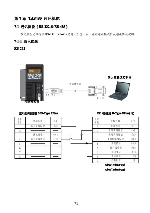
第7章TA8480通讯机能7-1通讯机能(RS-232&RS-485)本伺服驱动器提供RS-232、RS-485之通讯机能,以下针对通讯接线以及通讯协议说明。
7-1-1通讯接线RS-232通訊連接線接C N4R S-232個人電腦或控制器驱动器端使用MD-Type8Pins PC端使用D-Type9Pins(母)※Pin4及Pin6短路※Pin7及Pin8短路RS-485通訊連接線連接C N4R S-485R S-232 /R S-485轉換器個人電腦或控制器R S-232通訊連接線連接C N4R S-485個人電腦或控制器通訊連接線連接C N3連接C N4連接C N3R S-485R S-485R S-232 / R S-485轉換器驱动器端使用MD-Type8Pins RS-232/RS-485转换器注:CN3,CN4除接所需Pin脚外,其它Pin需留空,否则会导致驱动器烧毁。
RS-232、RS-485通讯相关参数参数代号名称与机能默认值单位设定范围控制模式索引章节FnH18数字输入接点控制方式选择H0000XH0000│H003F︵十六进制︶ALL5-6-17藉由位设定方式决定数字输入接点(共六点)由外部端子或采通讯控制;位设定采二进制换算十六进制方式;先将数字输入接点DI-1~DI-6分别对应二进制第0~5位,再将规划完成之二进制位换算为十六进制后设定。
二进制位表示:0:数字输入接点由外部端子控制1:数字输入接点由通讯控制参数设定为H0000即表示所有数字输入接点都由外部端子控制,设为H003F即表示所有数字输入接点由通讯控制。
例:欲设定数字输入接点DI-1、DI-3、DI-6采通讯控制,其余接点由外部端子控制;数字输入接点对应二进制位为:〔100101〕其中第0位设为1表示DI-1为通讯控制,第1位设为0表示DI-2为外部端子控制,其它位依此类推;换算十六进制后,即可设定为:〔H0025〕FnH19通讯控制数字输入接点状态H0000XH0000│H003F︵十六进制︶ALL5-6-17藉由位设定方式决定数字输入接点(共六点)采通讯控制时之接点状态;位设定方式请参考Hn510说明。
YAV 8AD-16高精度采集卡技术手册V1701武汉亚为电子科技有限公司YAV 6542注意序号版本号编写人编写日期支持对象应用时间特别说明1 1.0 郑先科2014.10 YAV 8AD-16采集卡2 2.0 郑先科2015.01 YAV 8AD-16采集卡3 3.0 郑先科2017.01 YAV 8AD-16采集卡目录功能概述 (5)技术指标 (5)1.模拟信号输入 (5)2.通信总线 ......................................................................................................... 错误!未定义书签。
3.温度条件 ......................................................................................................... 错误!未定义书签。
硬件特点 (6)原理框图 (6)端子信息 (7)1.端子排列 (7)2.端子描述 (8)电气参数 (9)通信 (9)采集卡指示灯 (9)机械规格 (9)模拟量输入功能 (11)模拟量输入 (11)输入采样原理 (11)输入接线 (11)采样值计算 (12)1.无符号整型 (12)2.ADC数据类型 (12)3.模拟量值 (13)通信协议 (14)MODBUS-RTU通信协议 (14)应用实例 (17)采集卡连接 (17)发现硬件 (18)软件功能 (18)软件应用 (18)bVIEW (18)2.MODBUS RTU通信 (19)3.组态及PLC (19)注意事项及故障排除 (22)注意事项 (22)1.存储说明 (22)2.出货清单 (22)3.质保及售后 (22)4.特别说明 (22)故障排除 (23)1.无法正常采集数据 (23)2.VI文件打不开 (23)3.多卡不识别 (24)4.不显示波形 (24)5.采集速度不够 (24)6.软件弹出错误 (24)性能测试 (25)安全规范 (25)耐电压范围测试 (25)环境适应性测试 (26)文档权利及免责声明 (27)联系方式 (28)V智能体验 (29)功能概述模块有12路16位AI,电源电压为12V。
多摩川公司磁阻式旋变产品手册目录1. 引言2. 产品概述3. 技术规格4. 产品特点5. 安装和使用指南6. 故障排除7. 常见问题解答8. 保养与维护9. 市场应用及案例分析10. 联系我们1. 引言欢迎阅读多摩川公司的磁阻式旋变产品手册。
本手册将为您提供关于我们磁阻式旋变产品的详细信息,包括技术规格、产品特点、安装和使用指南,以及常见问题解答等。
2. 产品概述多摩川公司磁阻式旋变是一种高品质的旋转传感器,采用磁敏电阻原理,能够准确测量角位移,并将其转换为电信号输出。
我们的磁阻式旋变产品具有高精度、高可靠性和长寿命等优点,广泛应用于工业自动化、机械控制和仪器仪表等领域。
3. 技术规格我们的磁阻式旋变产品具有以下技术规格:- 角度范围:0~360度- 分辨率:0.1度- 输出信号:模拟电压信号- 零点偏移:±0.5度- 工作温度:-40~85摄氏度- 输入电源:5V直流电源更详细的技术规格请参考产品说明书。
4. 产品特点- 高精度:我们的磁阻式旋变产品采用先进的磁敏电阻技术,能够实现高精度的角度测量,满足各种应用需求。
- 高可靠性:通过精心设计和严格生产流程,我们的产品具有高可靠性和稳定性,能够长时间稳定地工作。
- 长寿命:采用优质材料和先进制造工艺,我们的产品具有长寿命,可满足各种复杂环境下的使用。
- 易于安装:我们的磁阻式旋变产品提供多种安装方式,适用于不同的安装需求。
5. 安装和使用指南在安装和使用磁阻式旋变产品之前,请确保按照以下步骤进行操作:- 选择适当的安装方式,并将产品固定在合适的位置。
- 连接产品的电源和信号线。
- 根据产品说明书设置合适的参数。
- 在使用过程中,避免过度扭曲或碰撞产品,以免影响其准确性和精度。
6. 故障排除本章节将为您提供一些常见故障的诊断和解决方法,以帮助您解决可能遇到的问题。
7. 常见问题解答在此章节,我们列举了一些经常被用户问到的问题,并给出了详细的解答。
包括参数调整的各种设定,全部可用个人电脑来操作,而不需要专门的检测工具。
参照个人电脑画面的图表,可轻松设定参数。
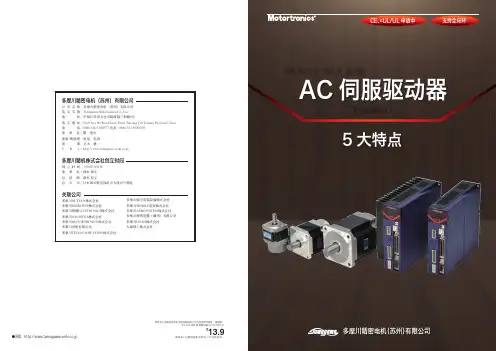
更直观追加了各种特性后AC 伺服驱动器重新诞生了.调整结束连接SV-NET 控制器,可构建简单又有高性能的运动控制系统。
/SV-NET 是以CAN 为基础的多摩川精机独特的 网络通信协议。
操作模式也可以简单设定运行范围操作为更直观的JOG 操作用FFT 功能可在个人电脑画面里显示整个装置的震动波形。
震 动F F TV alue.1开关PC电机电机电机Sensor触摸屏SV-NET 驱动器SV-NET 驱动器SV-NET 驱动器SV-NET 控制器系统构成NEW S V -NET 系列与本公司原有产品相比,大幅缩小了外形尺寸。
另外,与其它公司产品相比,也具有优异的精巧性。
·备有功能丰富的设置软件,可免费下载。
使用USB 与电脑连接,也可轻松设置。
按项目分类表示参数,可清晰易懂地显示当前值和变动值行业首次装备了报警记录器能够自动记录系统运行中的所有报警,因此,可以瞬间确定出不良部分。
记录内容为如下3 点。
报警发生的时间 报警编号 报警发生时的数据/位置偏差、速度、电流、负荷率、驱动电压、基板温度搭载了能预测驱动器寿命的计算功能记录运行过程中的通电时间等各种状況。
通过计算这些数据来预测驱动器寿命,可对装置进行风险管理。
P2H∶对应分解器、增量型、绝对型、17~23 bit。
网络∶对应SV-NET、RS485、RS232123按项目分类表示参数,可清晰易懂地显示当前值和变动值程序画面状况、报警显示画面电流响应 2.2kHz (行业最快级别)速度响应 1kHz通过改进硬件和软件,电流响应和速度响应均实现了原有产品两倍的速度。
※与本公司原有产品比较。
更方便更迅捷更精致V alue.2V alue.3V alue.4V alue.5·本行业中首次装备了报警记录器。
内置日历和时钟功能,可自动保存报警发生时的时间及数据。
陀螺仪:可应用于航空、航天、航海、兵器、汽车、生物医学、环境监控等领域。
1、体积小、重量轻。
适合于对安装空间和重量要求苛刻的场合,例如弹载测量等。
2、低成本。
3、高可靠性。
内部无转动部件,全固态装置,抗大过载冲击,工作寿命长。
4、低功耗。
5、大量程。
适于高转速大g值的场合。
6、易于数字化、智能化。
可数字输出,温度补偿,零位校正等。
测速发电机:输出电动势与转速成比例的微特电机。
测速发电机的绕组和磁路经精确设计,其输出电动势E和转速n成线性关系,即E=Kn,K是常数。
改变旋转方向时输出电动势的极性即相应改变。
在被测机构与测速发电机同轴联接时,只要检测出输出电动势,就能获得被测机构的转速,故又称速度传感器。
测速发电机广泛用于各种速度或位置控制系统。
在自动控制系统中作为检测速度的元件,以调节电动机转速或通过反馈来提高系统稳定性和精度;在解算装置中可作为微分、积分元件,也可作为加速或延迟信号用或用来测量各种运动机械在摆动或转动以及直线运动时的速度。
电子凸轮:利用角度位置传感器来模拟机械凸轮各控制点的角度范围,并能独立输出各自的控制信号,此种设备称为电子凸轮,包含“机械凸轮+微动开关”的基本功能。
•可以输出多路控制开关量(ON/OFF),且每路都可以独立预设起始、终止角度。
•可以动态检测和显示实际运行角度,对设备运行和再调整实时检测。
•可以随时修改预设角度,且每一路均有LED状态指示,“开态”点亮,“关态”熄灭。
•各路输出信号在电气上相互隔离,抗干扰能力强,可靠性高。
•动作精度可达到1°typical轨迹球:外型尺寸:1、1.4、2、3英寸输出方式:PS2、USB、方波、脉冲输出轨迹球外观:透明(七色光可选)、白色、黑色本产品有发光技术及三轴两项技术专利,产品精度高,寿命长,主要运用于医学行业中的B超、SMP、雷达、舰船等行业,国内市场占有率超过70%。
同步器:同步器有常压式和惯性式。
目前全部同步式变速器上采用的是惯性同步器,它主要由接合套、同步锁环等组成,它的特点是依靠摩擦作用实现同步。

7proBLem Instrument does not run or oscillates at a reduced speed making cutting difficult.Motor runs but blade does not move.Battery pack becomes unusually hot during use.Blade will not fit into the blade retainer or cannot be secured.Handpiece has become noisy and vibrates.Sporadic electrical interference is expe-rienced.Troubleshooting Guidelines**This product is not field repairable. In case of operating difficulties, all Stryker products must be returned to Stryker Instruments for repair. For more information, contact your Stryker Instruments sales representative or call Stryker Customer Service at -800-253-32 0. Outside the USA, contact your nearest Stryker subsidiary.cause Battery pack is discharged.Battery pack is expended.Trigger switch is in the SAFE position.Drivetrain is malfunctioning.Drivetrain is malfunctioning.Circuitry is malfunctioning.Debris is inside the end of the blade retainer.Blade is not a Stryker product.Blade retainer is damaged.Blade is not a Stryker product.Drivetrain is malfunctioning.Electrical noise is present.actIonRecharge the battery in Stryker charger.Replace the battery pack.Set the trigger switch to the FAST or STDposition.Return the handpiece for repair.Return the handpiece for repair.Check the battery pack on the Stryker charger and replace it if indicated. SeeCharger Instructions .Clean with a small brush.Use a Stryker blade.Return the handpiece for repair.Use a Stryker blade.Return the handpiece for repair.Turn off all electrical equipment not in use in the operating room.Relocate electrical equipment; increasespatial distance.Plug operating room equipment into differ-ent operating room outlets.storage and HandlingTo ensure the longevity, performance and safety of this equipment, package in original packaging materials when storing or transporting.Periodic MaintenanceInterVaL actIVItYPrior to each use. Inspect, operate and test the handpiece to ensure that it isworking properly. Ensure there are no loose or missing components. Check allmoving parts for free movement. Be alert for unusual sounds or vibrations and notethe operating speed.8guidance and manufacturer’s declaration - electromagnetic emissionsThe System 5 handpiece is intended for use in the electromagnetic environment specified below. The customer or the user of the System 5 handpiece should assure that it is used in such an environment.emissions testRF emissionsCISPRRF emissionsCISPRHarmonicemissionsIEC 6 000-3-2Voltagefluctuations/flicker emissionsIEC 6 000-3-3complianceGroupClass Bn/an/aelectromagnetic environment - guidanceThe System 5 handpiece uses RF energy only for its internal function.Therefore, its RF emissions are very low and are not likely to cause anyinterference in nearby electronic equipment.23guidance and manufacturer’s declaration - electromagnetic immunityThe System 5 handpiece is intended for use in the electromagnetic environment specified below. The customer or the user ofthe System 5 handpiece should assure that it is used in such an environment.Immunity testConducted RF IEC 6 000-4-6Radiated RF IEC 6 000-4-3Iec 60601 test level3 Vrms 50 kHz to 80 MHz3 V/m 80 MHz to 2.5 GHzcompliance leveln/a n/a3 V/m 80 MHz to 2.5 GHzelectromagnetic environment - guidancePortable and mobile RF communications equipment should be used no closer to any part of the System 5 handpiece, including cables, than the recommended separation distance calculated from the equation applicable to the frequency ofthe transmitter.Recommended separation distanced= .67√Pd= .67√P80 MHz to 800 MHz d=2.33√P800 MHz to 2.5 GHzWhere P is the maximum output power rating of the transmitter in watts (W) according to the transmitter manufacturer and d is the recommended separation distance in meters (m)Interference may occur in the vicinity of equipmentmarked with the following symbol:NOTE : At 80 MHz and 800MHz the higher frequency range applies.NOTE 2: These guidelines may not apply in all situations. Electromagnetic propagation is affected by absorption and reflection from structures, objects and people.guidance and manufacturer’s declaration - electromagnetic immunityThe System 5 handpiece is intended for use in the electromagnetic environment specified below. The customer or the user of the System 5handpiece should assure that it is used in such an environment.Immunity test Electrostatic discharge (ESD)IEC 6 000-4-2 Electrical fast transient/burstIEC 6 000-4-4SurgeIEC 6 000-4-5Voltage dips, short interruptions and voltage variations on power supplyinput linesIEC 6 000-4-Power frequency(50/60 Hz)magnetic fieldIEC 6 000-4-8Iec 60601test level±6 kV contact±8 kV air±2 kV for power supplylines± kV for input/outputlines± kV differential mode±2 kV common mode<5% UT(>95% dip in UT)for 0,5 cycle40% UT(60% dip in UT)for 5 cycles70% UT(30% dip in UT)for 25 cycles<5% UT(>95% dip in UT)for 5 sec3 A/mcompliance level±2, 4, 6 kV contact±2, 4, 8 kV airn/an/an/an/an/an/an/an/a3 A/mNOTE: UT is the a.c. mains voltage prior to application of the test level.electromagnetic environment - guidanceFloors should be wood, concrete or ceramic tile. If floorsare covered with synthetic material, the relative humidityshould be at least 30%.Power frequency magnetic fields should be at levelscharacteristics of a typical location in a typical commercialor hospital environment.45recommended separation distances between portable and mobile rf communications equipment and the system 5handpiece The System 5 handpiece is intended for use in the electromagnetic environment in which radiated RF disturbances are controlled. The customer or the user of the System 5 handpiece can help prevent electromagnetic interference by maintaining a minimum distance between portable and mobile RF communications equipment (transmitters) and the System 5 handpiece asrecommended below, according to the maximum output power of the communications equipment.rated maximum output power oftransmitterW0.0 0. 0 00150 kHz to 80 mHzd = [ — ]√Pn/a n/a n/a n/a n/a80 mHz to 800 mHzd = [ — ]√P 0. 20.37 . 73.70 .70800 mHz to 2.5 gHzd = [ — ]√P0.230.742.337.3723.30For transmitters rated at a maximum output power not listed above, the recommended separation distance d in meters (m) can be estimated using the equation applicable to the frequency of the transmitter, where P is the maximum output power rating of the transmitter in watts (W) according to the transmitter manufacturer.NOTE : At 80 MHz and 800MHz, the separation distance for the higher frequency range applies.NOTE 2: These guidelines may not apply in all situations. Electromagnetic propagation is affected by absorption and reflection from structures, objects and people.separation distance according to frequency of transmitterm3.5V 13.5E 17E 1。
RUGGED WET/WET DIFFERENTIAL PRESSURE TRANSDUCER WITH®WETTED PARTSDP41-S panel meter, $545, see page D-31.PX821-010DV, $1325, shown smaller than actual size.CONNECTIONS RED+EXCWHITE-EXC YELLOW+SIG BLUE-SIGDIFFERENTIALPRESSURE TRANSDUCERSB DISCONTINUEDDISCONTINUED DISCONTINUEDφ6CANADA www.omega.ca Laval(Quebec) 1-800-TC-OMEGA UNITED KINGDOM www. Manchester, England0800-488-488GERMANY www.omega.deDeckenpfronn, Germany************FRANCE www.omega.frGuyancourt, France088-466-342BENELUX www.omega.nl Amstelveen, NL 0800-099-33-44UNITED STATES 1-800-TC-OMEGA Stamford, CT.CZECH REPUBLIC www.omegaeng.cz Karviná, Czech Republic596-311-899TemperatureCalibrators, Connectors, General Test and MeasurementInstruments, Glass Bulb Thermometers, Handheld Instruments for Temperature Measurement, Ice Point References,Indicating Labels, Crayons, Cements and Lacquers, Infrared Temperature Measurement Instruments, Recorders Relative Humidity Measurement Instruments, RTD Probes, Elements and Assemblies, Temperature & Process Meters, Timers and Counters, Temperature and Process Controllers and Power Switching Devices, Thermistor Elements, Probes andAssemblies,Thermocouples Thermowells and Head and Well Assemblies, Transmitters, WirePressure, Strain and ForceDisplacement Transducers, Dynamic Measurement Force Sensors, Instrumentation for Pressure and Strain Measurements, Load Cells, Pressure Gauges, PressureReference Section, Pressure Switches, Pressure Transducers, Proximity Transducers, Regulators,Strain Gages, Torque Transducers, ValvespH and ConductivityConductivity Instrumentation, Dissolved OxygenInstrumentation, Environmental Instrumentation, pH Electrodes and Instruments, Water and Soil Analysis InstrumentationHeatersBand Heaters, Cartridge Heaters, Circulation Heaters, Comfort Heaters, Controllers, Meters and SwitchingDevices, Flexible Heaters, General Test and Measurement Instruments, Heater Hook-up Wire, Heating Cable Systems, Immersion Heaters, Process Air and Duct, Heaters, Radiant Heaters, Strip Heaters, Tubular HeatersFlow and LevelAir Velocity Indicators, Doppler Flowmeters, LevelMeasurement, Magnetic Flowmeters, Mass Flowmeters,Pitot Tubes, Pumps, Rotameters, Turbine and Paddle Wheel Flowmeters, Ultrasonic Flowmeters, Valves, Variable Area Flowmeters, Vortex Shedding FlowmetersData AcquisitionAuto-Dialers and Alarm Monitoring Systems, Communication Products and Converters, Data Acquisition and Analysis Software, Data LoggersPlug-in Cards, Signal Conditioners, USB, RS232, RS485 and Parallel Port Data Acquisition Systems, Wireless Transmitters and Receivers。
基于PLC的锁螺丝自动化控制系统设计王月芹;周保廷;朱伟博【摘要】针对自主开发的锁螺丝自动化生产设备,设计了基于可编程控制器(PLC)的控制系统,该系统融合了视觉定位、伺服驱动和人机交互等技术。
本系统应用于单相国网表自动化生产流水线,实现了表电压接线端子自动锁螺丝的控制功能。
本文从机械系统结构、控制系统硬件搭建、控制系统软件设计、报警系统、通信等方面进行了详细的介绍。
该设备运行可靠、参数调节方便、监控界面清晰,解决了现有生产线自动化程度低的问题,提高了产品生产效率。
【期刊名称】《制造业自动化》【年(卷),期】2014(000)017【总页数】5页(P152-156)【关键词】PLC;视觉定位;伺服驱动;触摸屏【作者】王月芹;周保廷;朱伟博【作者单位】苏州工业职业技术学院,苏州 215104;苏州汇川技术有限公司,苏州 215100;苏州自动化设备有限公司,苏州 215100【正文语种】中文【中图分类】TP2730 引言在现代化生产流水线中,自动控制技术起着越来越重要的作用,所谓自动控制,是指在没有人直接参与的情况,利用外加的设备或装置,使生产过程(统称被控对象)的某个工作状态或参数(即被控量)自动地按照预定的规律运行[1]。
单相国网表生产流水线中,表电压接线端子上需8个锁螺丝,传统方式是依靠人工进行手动锁螺丝,一方面严重影响了企业的产能,另一方面造成了不良产品的漏检。
企业要降低成本提高生产效率,急需研制出一台机械自动锁螺丝机。
本文设计了基于可编程控制器(PLC)的自动锁螺丝控制系统。
该系统融合了视觉定位、伺服驱动和人机交互等技术,实现了表电压接线端子自动锁螺丝的控制功能。
解决了现有生产线自动化程度低的问题,提高了产品生产效率。
1 自动锁螺丝机概述自动锁螺丝机是单相国网表自动化生产流水线中表电压接线端子锁螺丝自动化装置。
本系统具有单表自动上料,通过CCD对螺丝孔的视觉定位,找准相应螺丝孔中心位置,驱动锁螺丝单元,按设定的扭力锁螺丝,自动安装入表中所有螺丝,安装完毕,自动出料流至下道工序。
C S N 840 B e n e f i t sC S N 840 B e n e f i t s Automated dimensioning has been a staple for parcel carriers for years and is quickly becoming the same for freight carriers. During a recent test, one of the largest LTL companies was able to quickly see the ROI potential of automated dimensioning. The pilot test was a joint effort between the LTL company and METTLER TOLEDO. METTLER TOLEDO installed the CSN840 dimensioner in one of the LTL company’s major break bulk facilities. The test standard was that the forklift drivers were to measure approximately 400-500 pallets of freight a day without any prejudice as to size, shape or any other characteristic of the freight. After a month of data collection the LTL company was to compare this data to the actual bill of ladings to determine how much revenue an automated dimensioner could recover just by integrating it into an existing operation. The results were better than METTLER TOLEDO and the LTL company could have ever assumed. After the first month and the additional months to follow the stats looked like this: Average number of pallets measured per day ~ 450-500 Average number of pallets that could be reclassified based on density ~ 11 pallets Average potential revenue recovered on the pallets that could be reclassified based on density ~ $130 per pallet that was reclassified based on densityAverage daily revenue recovery just by automatically dimensioning 450-500 random pallets~ $1430Average monthly revenue recovery~ $28,600ROI of integrating a CSN840 dimensioner ~ Less than three monthsAs the results show, the LTL industry needs automated dimensioning. This test was completed without any assumptions made by the LTL company or the forklift drivers that were measuring the freight to determine which freight was more profitable to measure. If an LTL company can determine which freight is classified based on density and increase the number of pallets that are reclassified, or if they install this equipment where their freight is moving outbound via air or ocean and dimensions are always required, they can achieve the benefits even quicker.The benefits of automatic freight dimensioning do not stop with the carriers, they are beneficial to the shippers as well. In many cases companies who rely heavily on LTL carriers are already dimensioning manually. As discussed earlier, this is a time consuming manual process that fosters many opportunities for error. Shippers who utilize automated dimensioning can speed up their manual processes at the shipping dock as well as eliminate the cost of potential of human errors. We know freight carriers are auditing freight to ensure the weight and dimensions are accurate, and for any inaccuracies the carriers are required to incur the cost of the reclassification.If part of your supply chain requires freight shipping or if you are a freight carrier and you are that part of the supply chain, you need to consider automatic dimensioning. Automatic dimensioning can save companies time and money by ensuring accurate data is transmitted quickly and reliably every time. For freight carriers, this type of equipment is required to bill their customers properly and is essential for revenue recovery. For shippers of freight, companies need to make sure they are charging customers properly and protecting their revenue, while ensuring they are getting billed correctly. Companies invest a lot in the volume of products and services they provide, let METTLER TOLEDO assist in measuring the volume of those products by incorporating an automatic dimensioner in your supply chain!For more information/dimensioningMettler-Toledo, Inc.Tel. (866) 339-3538Fax (614) 781-2452Internet: Specifications subject to change without noticeMETTLER TOLEDO ® is a registered trademarkof Mettler-Toledo, Inc.Printed in USA.SAC-0209-LIT。