CC1瓷片电容规格书
- 格式:pdf
- 大小:465.07 KB
- 文档页数:5
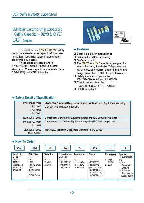
承認書APPROVAL SHEET零件名稱:積層陶瓷電容Description :Multi-Layer Chip CapacitorDATE :20020099/1201深圳市宸远科电子有限公司ChipCera Technology CO.,LTD 深圳市宝安区银田工业区A9栋厂房TEL :+86-7+86-7555555--29120592FAX :+86-7+86-7555555--29120593Reference No.:PD0PD091201912019120100000011Customer Customer::宸遠科技料號CCT Part Numbers客戶料號Customer Customer’’s Part Numbers 宸遠科技ChipCera Technology Co.,LTD 客戶承認Customer Customer’’s Approval 製表Prepared by 審查Checked by 核准Approved byEngineer QA Manager Vice G.M.Tolerance Capacitance for dielectricA=±0.05pF B=±0.10pF C=±0.25pF D=±0.50pF F=±1.0% G=±2.0% J=±5.0% K=±10% M=±20%NP0X7R X5R Y5V 10pF and below More than10pF100pF~1μF(101~105)1uf~100uf(105~107)10nF~10uF(103~106) B,C,D G,J J,K,M K,M M,ZProduct dimensions in mm.X7R SeriesX7R/X5R SeriesY5V Series7Resistance tosoldering heatPreheat the capacitor at120℃to150℃for1minute.Immerse the capacitor in an eutectic soldersolution at270270±±5℃for1010±±1seconds.After set it atroom temperature for2424±±2hours(temperaturecompensation type)or4848±±4hours(high dielectricconstant type),then measure.*High dielectric constant type:Initial measurement of X7RX7R/X5R/X5R and Y5V.Perform a heat treatment at150150±±5℃for one hourand then set it at room temperature for4848±±4hours.Perform the initial measurement.Dielectric NP0X7RX7R//X5RY5VAppearance No defectCapacitanceChange<±2.5%or<±0.25pF±7.5%±20%DF The same as No.2IRMore than500500ΩΩ-F(whichever is smaller)DielectricStrengthNo failure8Resistance toleachingThe capacitors are dipped into the solder at260260±±5℃for3030±±1seconds,and then check the solderingby measuring the areas covered with solder.95%of the terminations are to be soldered evenly andcontinuously.9Solder ability ofterminationZero hour test,and test after storage(20to24months)in original atmosphere in normalatmosphere;un-mounted chips completelyimmersed for2±0.5s in a solder bath of235±5℃.95%of the termination is to be soldered evenly andcontinuously.10Rapid change oftemperatureNPO/X7R:-55℃to+125℃,5cycleX5R:-55℃to+85℃,5cycleY5V:-25℃to+85℃,5cycleDuration:30mins.Recovery:24±2hrs.No visible damage after24h recoveryClass I NPO:∆C/C≤2.5%or±0.25pFClassⅡX7RX7R/X5R/X5R/X5R::∆C/C≤±15%Y5V:∆C/C≤±20%11Damp heat,steadystate500±12hours at40±2℃;90to95%RHNo visible damage after24±2(NPO)or48±4hoursrecoveryClassⅠ(NPO)1.∆C/C±5%or1pF,whichever is greater2.C<10pF;Q≥200+10C10≤C≤30pF;Q≥275+5/2CC>30pF;Q≥3503.IR≥4000MΩorRiCR≥4040ΩΩF,whichever is lessClassⅡ(X7R(X7R/X5R/X5R/X5R))1.∆C/C within±15%2.2.tantanδ≤7%3.3.R R≥2000MΩorRiCR≥5050ΩΩF,whichever is lessClassⅡ(Y5V)1.∆C/C within±30%2.50/25V:tanδ≤9%16V:tanδ≤12.5%10V:tanδ≤15%3.IR≥2000MΩorRiCR≥5050ΩΩF,whichever is less12Endurance 1000h at maximum temperatureVr(rated voltage)≤250VAt2×V rVr(rated voltage)=500VAt1.5VrVr(rated voltage)>500VAt1.2VrC>0..1UF,At1.5VrNo visible damage after24±2(NPO)or48±4hoursrecoveryClass1(NPO)1.∆C/C±2%or1pF,whichever is greater2.tanδ≤2x specified value3.IR≥4000MΩor RiCR≥4040ΩΩF,whichever is lessClass2(X7R(X7R/X5R/X5R/X5R))1.∆C/C within±15%2.tanδ≤7%3.IR≥2000MΩor RiCR≥5050ΩΩF,whichever is lessClass2(Y5V)1.∆C/C within±30%2.50/25V:tanδ≤9%16V:tanδ≤12.5%3.IR≥2000MΩor RiCR≥5050ΩΩF,whichever is lessAll dimensions in mmSize SymbolABPLT(Paper)T(Embossed)04020.62±0.05 1.12±0.05 2.00±0.058.00±0.200.60±0.05N/A 0603 1.10±0.10 1.90±0.10 4.00±0.108.00±0.20 1.00±0.05N/A 0805 1.65±0.05 2.40±0.05 4.00±0.108.00±0.20 1.00±0.05N/A 1206 2.00±0.10 3.50±0.10 4.00±0.108.00±0.20 1.00±0.05Max.2.01210 2.80±0.20 3.70±0.20 4.00±0.108.00±0.20N/A Max.2.01808 2.50±0.30 4.90±0.30 4.00±0.1012.0±0.20N/A Max.2.518123.60±0.304.90±0.308.00±0.1012.0±0.20N/AMax.2.5Paper Tape T ≦1.1mmEmbossed Tape T ≦2.60mm8.4+1.5/-0 All dimensions in mm6.1Capacitor ClassificationMulti-layer ceramic capacitors are available in wide range of characteristics.Electronic Industries Association (EIA)and the military have established categories to help divide the basic characteristics into more easily specified classes.The basic indu industrystry specification for ceramic capacitor is EIA specification RS-198and as noted in the general section,it specifies temperature-compensating capacitors as class I capacitors.These are specified by the military under specification MIL-C-20.General-pur General-purposepose capacitors with non-linear temperature coefficients are called Class II capacitors by EIA and specified by military under MIL-C-11015and MIL-C-39014.The new high reliability military specification,MIL-C-123covers both class Iand class II dielect dielectrics.rics.Class I —Class I capacitors or temperature-compensating capacitors are usually made from mixtures of titanates where barium titanate is normally not a major part of mix.They have predictable temperature coefficients and in general,do not have an aging characteristic.Thus they are the most stable capacitor available.Normally the T.C.s of Class I temperature-compensating capacitors are NP0(±30ppm/℃).Class II —General-purpose ceramic capacitors are called Class II capacitors and have become extremely popular because of the high capacitance values available in very small size.These capacitors are ferroelectrics and vary in capacitance value under the influence of the environmental and electrical operating conditions.Class II capacitors are affected by temperature 、voltage 、frequency and time.Temperature effects for Class II ceramic capacitors are exhibited as non-linear capacitancechanges with tem temperature.perature.Industry standards for Mid-K dielectrics,such as X7R X7R/X5R /X5R and High-K dielectrics,such as Z5U Z5U..6.2The Characterization of MaterialsThe T.C curve of each material (for reference)DesignationClass Temperature Range (℃)Temp.Characteristics NPO(COG)I -55~+125±30ppm/℃X7RII -55~+125±15%X5RII -55~+85±15%Y5V II -25~+85-82~+22%6.3Recommend IR reflow and wave solderng profile(Pb-Free)Typical profile band of IR reflow Typical profile band of wave soldering。
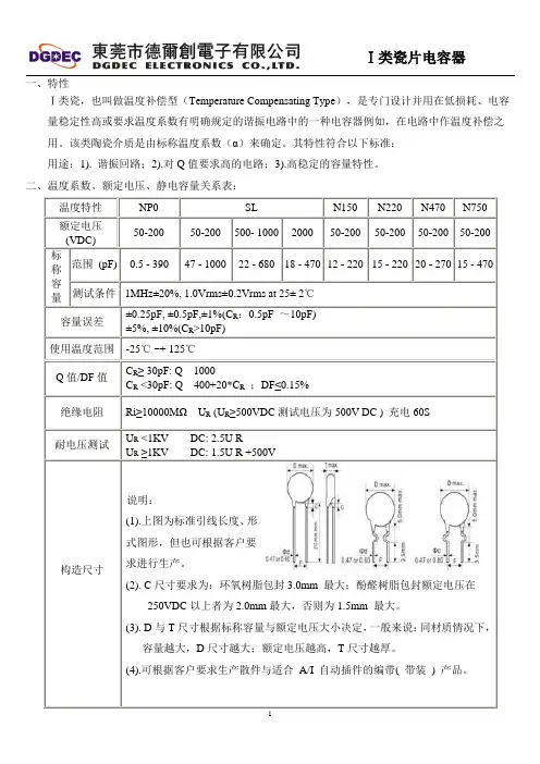
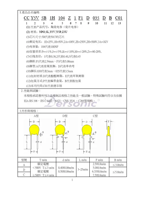
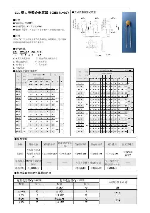
一、特性Ⅰ类瓷,也叫做温度补偿型(Temperature Compensating Type),是专门设计并用在低损耗、电容量稳定性高或要求温度系数有明确规定的谐振电路中的一种电容器例如,在电路中作温度补偿之用。
该类陶瓷介质是由标称温度系数(α)来确定。
其特性符合以下标准:用途:1). 谐振回路;2).对Q值要求高的电路;3).高稳定的容量特性。
二、温度系数、额定电压、静电容量关系表:温度特性NP0 SL N150 N220 N470 N750额定电压(VDC)50-200 50-200 500- 1000 2000 50-200 50-200 50-200 50-200标称容量范围(pF) 0.5 - 390 47 - 1000 22 - 680 18 - 470 12 - 220 15 - 220 20 - 270 15 - 470 测试条件 1MHz±20%, 1.0Vrms±0.2Vrms at 25± 2℃容量误差±0.25pF, ±0.5pF,±1%(C R:0.5pF ~10pF) ±5%, ±10%(C R>10pF)使用温度范围-25℃ ~+ 125℃Q值/DF值C R≥ 30pF: Q1000C R <30pF: Q400+20*C R;DF≤0.15%绝缘电阻Ri≥10000MΩU R (U R≥500VDC测试电压为500V DC ) 充电60S耐电压测试U R <1KV DC: 2.5U RU R≥1KV DC: 1.5U R +500V构造尺寸说明:(1).上图为标准引线长度、形式图形,但也可根据客户要求进行生产。
(2). C尺寸要求为:环氧树脂包封3.0mm 最大;酚醛树脂包封额定电压在250VDC以上者为2.0mm最大,否则为1.5mm 最大。
(3). D与T尺寸根据标称容量与额定电压大小决定,一般来说:同材质情况下,容量越大,D尺寸越大;额定电压越高,T尺寸越厚。
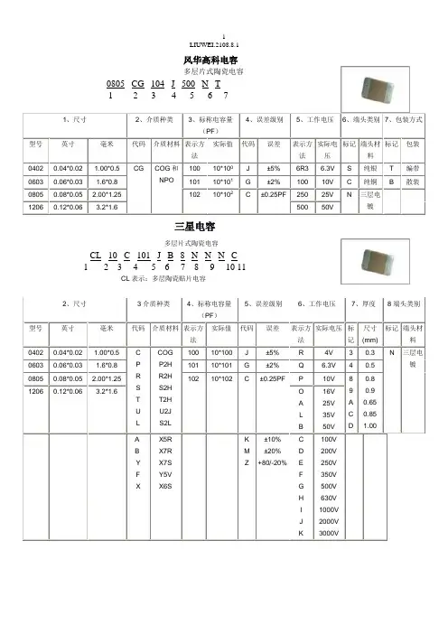
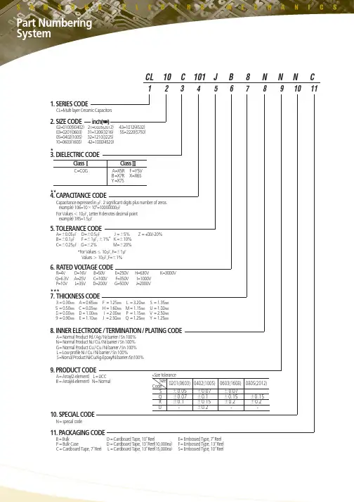
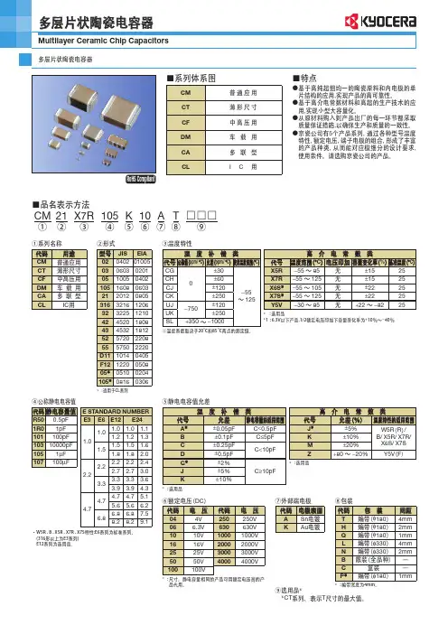
风华高科电容多层片式陶瓷电容0805 CG 104 J 500 N T1 2 3 4 5 6 71、尺寸2、介质种类3、标称电容量(PF)4、误差级别5、工作电压6、端头类别7、包装方式型号英寸毫米代码介质材料表示方法实际值代码误差表示方法实际电压标记端头材料标记包装0402 0.04*0.02 1.00*0.5 CG COG和NPO 100 10*100J ±5% 6R3 6.3V S 纯银T 编带0603 0.06*0.03 1.6*0.8 101 10*101G ±2% 100 10V C 纯铜 B 散装0805 0.08*0.05 2.00*1.25 102 10*102 C ±0.25PF 250 25V N 三层电镀1206 0.12*0.06 3.2*1.6 500 50V三星电容多层片式陶瓷电容CL 10 C 101 J B 8 N N N C1 2 3 4 5 6 7 8 9 10 11CL表示:多层陶瓷贴片电容2、尺寸3介质种类4、标称电容量(PF)5、误差级别6、工作电压7、厚度8端头类别型号英寸毫米代码介质材料表示方法实际值代码误差表示方法实际电压标记尺寸(mm)标记端头材料0402 0.04*0.02 1.00*0.5 CPRSTUL COGP2HR2HS2HT2HU2JS2L100 10*100 J ±5% R 4V 3 0.3 N 三层电镀0603 0.06*0.03 1.6*0.8 101 10*101 G ±2% Q 6.3V 4 0.50805 0.08*0.05 2.00*1.25 102 10*102 C ±0.25PF P 10V 89ACD0.8 0.9 0.650.851.001206 0.12*0.06 3.2*1.6 OALB 16V 25V 35V 50VAB Y F X X5RX7RX7SY5VX6SKMZ±10%±20%+80/-20%CDEFGHIJK100V200V250V350V500V630V1000V2000V3000V国巨(YAGEO)电容多层片式陶瓷电容CC ×××× × ×NPO ×BN ×××1 2 3 4 51、尺寸2、误差精度3、包装形式4、实际电压值5、标称电容量型号英制型号公制代码误差表示方法实际值代码电压代码实际值0201 0603 BCDFGJ±0.1PF±0.25PF±0.5PF±1%±2%±5%R 纸卷盘7inch 7 16V 100 10*1000402 1005 K 吸塑卷盘7inch 8 25V 101 10*101 0603 1608 P 纸卷盘13inch 9 50V 102 10*102 0805 2012 F 吸塑卷盘13inch1206 3216 C 散装1210 32251812 4532TDK贴片电容型号TDK贴片电容的参数识别C 2012 X7R 1H 104 K T系列名称体积材料电压容量误差包装0603=0201 CH 0J=6.3V C=0.25 T=卷带1005=0402 COG 1A=10V D=0.5 B=袋装1608=0603 JB 1C=16V J=5%2012=0805 JF 1E=25V K=10%3216=1206 X7R 1H=50V M=20%3225=1210 X5R 2A=100V Z=+80-20%4532=1812 Y5V 2E=250V5650=2220 2J=630V4520=1808 3A=1KV3D=2KV3F=3KV。
产品规格表示方式Product Part Number Expression1Product Type、产品类型CC11F 253NPO 415A 63307J 8S 9P 102Voltage Code、电压代码代码Code 额定电压Rated VoltageY 400VACF50V G100V A200V K250V L500V N1KV M2KVP3KV Q4KV 3Diameter Coefficient、片径直径代码直径Code Diameter(mm)65.5-6.4…………109.5-10.41211.5-12.4…………4(EIA )、温度特性见温度系数及代码:Temperature Characteristics (Please to see temperature coefficient and EIA code):5Lead style、引线形式代号symbol12345679W 11风华高科X250VAC54.5-5.4产品类型Product Type类型代号Typ e cod eLow voltage temperature compensation capacitor High voltage temperature compensation capacitorLow voltage high dielectric constant disk ceramic capacitor High voltage high dielectric constant disk ceramic capacitor Semiconductor disk ceramic capacitor Alternating current disk ceramic capacitor低压温度补偿型高压温度补偿型低压高介电常数型高压高介电常数型半导体型电容器交流电容器CC1CC81CT1CT81CS1CT7引线形式直脚长式直脚长式()编带直脚型(b式)编带小内弯型(a式)编带大内弯型(a式)特殊直脚S 外单弯(w式)前后翘lead Style(18-28mm)b Straight lon g lead (18~28m )b Style (16-20mm)b Straight long le ad (16~20mm)b Style straight short lead(cut the feet)Tape straight lead (b Style)Tape sm all inside kink (a Style)Tape large inside kink (a Sty le)()Special Straight lead (S)Outside kink(w Style)vertical kink lead短脚切脚6Lead Spacing、脚距7Standard capacitance、标称容量1R04R7100560821102-----注:标称容量以为单位,用位数字表示。