Skinner(美国产)系列比例调节电磁阀(介质空气
- 格式:pdf
- 大小:60.61 KB
- 文档页数:4

128Catalog 9EM-TK-190-1Pneumatic Division Richland, MichiganAcce p Filter / Regulator B03Features• Excellent Water Removal Efficiency • Unbalanced Poppet Standard • Solid Control Piston for Extended Life• Space Saving Package offers both Filter and Regulator features in One Integral Unit • Non-rising Adjustment Knob • Two Full Flow 1/8" Gauge PortsSpecificationsFlow Capacity* 1/8 16 SCFM (7.5 dm 3/s)1/4 18 SCFM (8.5 dm 3/s)Gauge Ports (2) 1/8 Inch Port Threads1/8, 1/4 InchPressure & Temperature Ratings – Plastic Bowl 0 to 150 PSIG (0 to 10.4 bar)32°F to 125°F (0°C to 52°C) Metal Bowl 0 to 250 PSIG (0 to 17.3 bar)32°F to 175°F (0°C to 80°C)Secondary Pressure Ranges –Standard Pressure2 to 125 PSIG (0 to 8.6 bar) Medium Pressure 1 to 60 PSIG (0 to 4.1 bar)Medium Pressure1 to 30 PSIG (0 to 2.1 bar) Low Pressure 1 to 15 PSIG (0 to 1.0 bar)Weight .4 lb. (.18 kg)Bowl Capacity1 Ounce* Inlet pressure 100 PSIG (6.9 bar). Secondary pressure 90 PSIG (6.2 bar). and 10 PSIG pressure drop.Materials of ConstructionAdjusting Nut Brass Adjusting Stem & SpringSteel BodyZinc Bonnet, Knob, Seat, Piston, Holder & DeflectorPlasticBowls – Transparent PolycarbonateMetal (Without Sight Gauge) ZincFilter Elements – 5 Micron (Standard) Plastic Manual Drain – Body & StemPlastic SealsNitrile Piston Drain – Piston & Seals Nitrile Stem, Seat, Adaptor & Washers AluminumSealsNitrileDimensionsWith Piston DrainB03-02-0000WARNINGProduct rupture can cause serious injury.Do not connect regulator to bottled gas.Do not exceed maximum primary pressure rating.!NOTE: 1.218 Dia. (31mm) hole required for panel mounting.(Revised 2-26-07)Catalog 9EM-TK-190-1129Pneumatic Division Richland, MichiganOrdering Information206080401001234562468101214Relief And Flow CharacteristicsS e c o n d a r y P r e s s u r e - P S I GS e c o n d a r y P r e s s u r e - b a rRated Flow - SCFMFlow - dm /s3n20608040100123456 Relief And Flow CharacteristicsS e c o n d a r y P r e s s u r e - P S I GS e c o n d a r y P r e s s u r e - b a rFlow - dm /s3nReplacement KitsPoly Bowl –Piston Drain ...............................................................PS408B Manual Drain ................................................................PS404Metal Bowl –Piston Drain ................................................................PS451B Manual Drain .............................................................PS447B Filter Element Kit, 5 Micron ..............................................PS403AccessoriesGauges –30 PSIG (0 to 2.1 bar) .......................................K4515N18030 60 PSIG (0 to 4.1 bar) .......................................K4515N18060 160 PSIG (0 to 11.0 bar) ...................................K4515N18160Mounting Bracket Kit (Includes Panel Mount Nut) .........PS417B Panel Mount Nut –Plastic ........................................................................P78652 Metal ...........................................................................P01531Poppet Valve Kit ...........................................................PS424B Service Kits –Non-Relieving ...............................................................PS422 Relieving .......................................................................PS423Springs –1 to 15 PSIG Range .....................................................P01176 1 to 30 PSIG Range .....................................................P01175 1 to 60 PSIG Range .....................................................P011742 to 125 PSIG Range ...................................................P01173CAUTION:REGULATOR PRESSURE ADJUSTMENT – The working range of knob adjustment is designed to permit outletpressures within their full range. Pressure adjustment beyond this range is also possible because the knob is not a limiting device. This is a common characteristic of most industrial regulators, and limiting devices may be obtained only by special design.For best performance, regulated pressure should always be set by increasing the pressure up to the desired setting.Filter / Regulator B03。
Doc. No.EX##-OMA1006SI Unit for ejector system integrated valve manifoldEX260-PEC1Safety InstructionsThese safety instructions are intended to prevent hazardous situations and/or equipment damage. These instructions indicate the level of potential hazard with the labels of "Caution", "Warning" or "Danger". They are all important notes for safety and must be followed in addition to International Standards (ISO/IEC)*1), and other safety regulations.*1) ISO 4414: Pneumatic fluid power -- General rules relating to systems.ISO 4413: Hydraulic fluid power -- General rules relating to systems.IEC 60204-1: Safety of machinery -- Electrical equipment of machines .(Part 1: General requirements)ISO 10218: Manipulating industrial robots -Safety.etc.Safety InstructionsRead and accept them before using the product.NOTE○Follow the instructions given below when designing, selecting and overseeing the product.•The instructions on design and selection (installation, wiring, environment, adjustment, operation,maintenance, etc.) described below must also be followed.*Product specifications•Use the specified voltage.Otherwise, failure or malfunction can result.•Reserve a space for maintenance.Allow sufficient space for maintenance when designing the system.•Do not remove any nameplates or labels.This can lead to incorrect maintenance, or misreading of the operation manual, which could cause damage or malfunction to the product.It may also result in non-conformity to safety standards.•Pay attention to the inrush current at power-up.Depending on the connected load, the initial charge current may cause the overcurrent protection and malfunction can result.•Product handling*Installation•Do not drop, hit or apply excessive shock to the fieldbus system.Otherwise, damage to the product can result, causing malfunction.•Tighten to the specified tightening torque.If the tightening torque is exceeded the mounting screws may be broken.IP67 protection cannot be guaranteed if the screws are not tightened to the specified torque.• When carrying the manifold, make sure that the connections are not stressed.Otherwise, the damage to connections can result. In addition, some combinations of the manifold may be very heavy, so use more than one person to carry or install the manifold.•Never mount a product in a location that will be used as a foothold.The product may be damaged if excessive force is applied by stepping or climbing onto it.*Wiring•Avoid repeatedly bending or stretching the cables or placing heavy load on them.Repetitive bending stress or tensile stress can cause breakage of the cable.•Wire correctly.Incorrect wiring can break the product.•Do not perform wiring while the power is on.Otherwise, damage to the fieldbus system and/or I/O device can result, causing malfunction.•Do not route wires and cables together with power or high voltage cables.Otherwise, the fieldbus system and/or I/O device can malfunction due to interference of noise and surge voltage from power and high voltage cables to the signal line.Route the wires (piping) of the fieldbus system and/or I/O device separately from power or high voltage cables.•Confirm proper insulation of wiring.Poor insulation (interference from another circuit, poor insulation between terminals, etc.) can lead to excess voltage or current being applied to the product, causing damage.•Take appropriate measures against noise, such as using a noise filter, when the fieldbus system is incorporated into equipment.Otherwise, noise can cause malfunction.*Environment•Select the proper type of protection according to the environment of operation.IP67 protection is achieved when the following conditions are met.However, when connected with JSY1000 manifolds, it is IP40.(1) The SI Unit is connected properly with fieldbus cable with M8 connector and power cable with M8 connector.(2) Suitable mounting of the SI Unit and manifold.(3) Be sure to fit a seal cap on any unused connectors.If using in an environment that is exposed to water splashes, please take measures such as using a cover.•Do not use in a place where the product could be splashed by oil or chemicals.If the product is to be used in an environment containing oils or chemicals such as coolant or cleaning solvent, even for a short time, it may be adversely affected (damage, malfunction etc.).•Do not use the product in an environment where corrosive gases or fluids could be splashed.Otherwise, damage to the product and malfunction can result.•Do not use in an area where surges are generated.If there is equipment that generates a large amount of surge (solenoid type lifter, high frequency induction furnace, motor, etc.) close to the fieldbus system, this may cause deterioration or breakage of the internal circuit of the fieldbus system. Avoid sources of surge generation and crossed lines.•When a surge-generating load such as a relay or solenoid is driven directly, use a fieldbus system with a built-in surge-absorbing element.Direct drive of a load generating surge voltage can damage the fieldbus system.•The product is CE marked, but not immune to lightning strikes. Take measures against lightning strikes in the system.•Prevent foreign matter such as remnant of wires from entering the fieldbus system to avoid failure and malfunction.•Mount the product in a place that is not exposed to vibration or impact.Otherwise, failure or malfunction can result.•Do not use the product in an environment that is exposed to temperature cycle.Heat cycles other than ordinary changes in temperature can adversely affect the inside of the product.•Do not expose the product to direct sunlight.If using in a location directly exposed to sunlight, shade the product from the sunlight.Otherwise, failure or malfunction can result.•Keep within the specified ambient temperature range.Otherwise, malfunction can result.•Do not operate close to a heat source, or in a location exposed to radiant heat.Otherwise, malfunction can result.*Adjustment and Operation•Perform settings suitable for the operating conditions.Incorrect setting can cause operation failure.•Please refer to the PLC manufacturer's manual etc. for details of programming and addresses. For the PLC protocol and programming refer to the relevant manufacturer's documentation.*Maintenance•Turn off the power supply, stop the supplied air, exhaust the residual pressure and verify the release of air before performing maintenance.There is a risk of unexpected malfunction.•Perform regular maintenance and inspections.There is a risk of unexpected malfunction.•After maintenance is complete, perform appropriate functional inspections.Stop operation if the equipment does not function properly.Otherwise, safety is not assured due to an unexpected malfunction or incorrect operation.•Do not use solvents such as benzene, thinner etc. to clean each unit.They could damage the surface of the body and erase the markings on the body.Use a soft cloth to remove stains.For heavy stains, use a cloth soaked with diluted neutral detergent and fully squeezed, then wipe up the stains again with a dry cloth.Fieldbus System/Industrial IoT Cybersecurity In recent years, factories have introduced industrial IoT, building up complex networks of production machines. These systems maybe subject to a new threat, cyberattack. To protect the industrial IoT from cyberattacks, it is important to take multiple measures (multi-layer protection) for IoT devices, networks and clouds.For this purpose, SMC recommends that the following measures are always taken into consideration. For further details of the following measures, please see security information published by your local country security agencies.1. Do not connect the devices via a public network.• If you unavoidably need to access the device orcloud via a public network, ensure to use a secure,private network such as VPN.• Do not connect an office IT network and factory IoT network.2. Build a firewall to prevent a threat from entering the device and system.• Set up a ro uter or firewall at network boundaries toallow minimum required communications.• Disconnect from the network or turn off the device if no continuous connection is required.3. Physically block an access to unused communication ports or disable them.• I nspect regularly each port if any unnecessarydevice is connected to the network system.• Operate necessary services (SSH, FTP, SFTP, etc.) only.• Set a transmission range of the device using awireless LAN or other radio system to the minimumrequired and use only devices approved according to the radio act in the country concerned.• Install a device generating radio waves in such place as there is no interference from indoor or outdoor. 4. Set up a secure communication method such as data encryption.• Encrypt data in every environment, including IoTnetworks, secure gate-way connections, for securecommunications.5. Grant access permissions by user accounts and limit the number of users.• Regularly review accounts and delete all unusedaccounts or permissions.• Establish an account lockout system to block anaccess to the account for a certain period if log-infails more than the given threshold.6. Protect passwords.• Change the default password when you firstuse the device or system.• Choose a long password (minimum 8characters) using a mix of different letters and characters to make the password more secure and harder to hack.7. Use the latest security software.• Install antivirus software on all computers todetect and remove viruses.• Keep the antivirus software up to date.8. Use the latest version of the device and system software.• Apply patches to keep the OS and applications up to date.9. Monitor and detect abnormalities in the network.• Keep monitoring t he network for anyabnormalities to take a prompt measure andissue an alert if any abnormality is detected.Install an intrusion detection system (IDS) and intrusion prevention system (IPS).10. Delete data from devices when disposed of. • Before disposi ng of any IoT devices, deletestored data or physically destruct media toprevent any misuse of the data.1.This document is an operation manual for a SI (Serial Interface) Unit which controls ejector system integrated valve manifold (JSY series). The SI Unit is a EtherCAT®-compatible device. EtherCAT® is registered trademark and patented technology, licensed by Beckhoff Automation GmbH, Germany. The SI Unit controls the manifold which has 5 pressure sensors max., and 24 valves output max.. For valve manifold, refer to the instruction manual for ejector system integrated valve manifold.Fig 1-1. The SI Unit structure2.Select the appropriate cables to mate with the connectors mounted on the SI Unit.2.1. Communication connectorECAT IN/OUT: M8 4 pin socket A-codedFig 2-1. Pin allocation of communication connectorWarningPay attention not to confuse the communication connector with the power connector. Incorrect connection may result in SI Unit failure. Check the printed character.2.2. Power connectorPWR IN: M8 4 pin plug A-codedPWR OUT: M8 4 pin socket A-codedFig 2-2. Pin allocation of power connectorPower-supply line for logic/sensors and power-supply line for valves are isolated. Be sure to supply power respectively.It can be used either with two different power supply or single-source power supply.NOTEThe recommended tightening torque is 0.2 Nm for both communication connectors and powerconnectors.2.3. FE terminalThe SI Unit must be connected to FE (Functional Earth) to divert electromagnetic interference. Connect a grounding cable from the FE terminal screw on the SI Unit to the nearest functional earth point. The grounding cable should be as thick and short as reasonably possible.The FE terminal and the metal parts of the communication/power connector are internally connected. The recommended tightening torque for FE terminal is 0.3 Nm.Fig 2-3. FE terminal3.1. ESI fileTo configure the SI Unit with your EtherCAT® master's software, the dedicated ESI (EtherCAT Slave Information) file is required. The ESI file contains all necessary information to configure the SI Unit on your master's software.The ESI file name is as follows. The ESI file can be downloaded from the SMC website.•ESI file: SMC_EX260-PECx_V10.xml3.2. Energy saving parameterNOTE•For energy saving function of ejector, see e.g. the catalogue for ejector system integrated valve manifold.The energy saving function is supported by ejector that can hold vacuum pressure.Check in advance whether your ejector is compatible with the energy saving function.•If there is an overlap OUT No. or order error in the set values, the Diagnosis history "Warning"occurs and SF LED flashes green and stops energy saving operation for sensor No. with error.•Incorrect OUT No. setting may result in unintended valve output.4.1. Input process data4.1.1. Pressure value of sensor No.x (of each 5 sensors)NOTE•Fixed at 0 for unconnected sensor.•Hold last data during happened sensor wire break and error etc..4.1.2. Valve-coil(s) short circuit diagnosis4.1.3. Unit diagnosis4.1.4. Sensor state of sensor No.x (of each 5 sensors)NOTEFor judgement of vacuum/pressure generation, refer to Section 5.1.1 and Section 6.4.2. Output process data4.2.1. Output5.NOTE*1) RO means Read only, WO means Write only, and RW means both Read and Write are allowed. Those with a trailing P are the Index assigned to the process data, and the format is the same.5.1. Sensor parameters(Index 0x8009/8019/8029/8039/8049)5.1.1. Pressure parameter (Subindex 0x01...0x08)NOTE•If the pressure parameter set values do not fulfil the conditions in (1)...(4) above, the Diagnosis history "Warning" occurs and SF LED flashes green and applicablevacuum/pressure state bit (Offset 0.0...0.3 in Section 4.1.4) is fixed at 0 for the applicable sensor.•If the pressure parameter set values do not fulfil the conditions in (2) above and the energy saving parameter is set to other than Disable, stop energy saving operation for the applicable sensor.5.1.2. Supply valve type (Subindex 0x09)NOTE•The setting must match supply valve type of actual ejector. If the settings are different from the actual specifications, energy saving operation is not possible.5.1.3. Valve protection (Subindex 0x0A)5.2. Output parameters5.2.1. Output counter (Index 0xF120)5.2.2. Output operation at network fault (Index 0xF800)5.2.3. Output counter limit monitoring(Index 0xF801)5.2.4. Output counter limit value (Index 0xF802)5.3. General parameters5.3.1. Number of sensors (Index 0xF803)NOTE•If the number of sensors detected by the SI Unit is greater than the set number, the unit will operate normally without occurring an error.5.4. Command parameters5.4.1. Zero offset (Index 0xB008/B018/B028/B038/B048/FB00)NOTE•Zero offset should be performed with sensor open to the atmosphere.Zero offset is performed only when the pressure value is within ±2 % F.S. of atmospheric pressure.•"Zero offset reset request" clears the zero offset correction.•"Zero offset of all sensors" is used to zero offset all sensors at once.5.4.2. Valve protection release (Index 0xFB01)NOTE•Valve protection release is performed for all ejectors at once.•If the valve protection occurs, the diagnostic bit will be deleted, and the SF LED will be turned off by the above requests.5.4.3. Output count reset (Index 0xFB02)NOTE•The Output count reset can be reset for each output individually and is entered according toa 4 byte (32 bit) number.Example: Set 0x00001234 -> Output count reset request of OUT2,4,5,9,12Example: Set 0x1234ABCD -> Output count reset request of OUT0,2,3,6,7,8,9,11,13,15,18,21•If output count over occurs, the diagnostic bit will be deleted, and the SF LED will be turned off by the above requests.6.Fig 6-1. Example of energy saving operation (Conditions under which release pressure is generated) • (1)When the vacuum instruction is ON, the supply valve is automatically closed when the vacuum pressure reaches P2.• (2)When the vacuum pressure drops by P2-H2, the supply valve is automatically opened again. • (3)Repeat steps (1) and (2) unless the valve protection is activated.• (4)The vacuum P1 state bit is set to 1 until the vacuum pressure reaches P1 and then drops to P1-H1. • (5)The vacuum P2 state bit is set to 1 until the release pressure reaches P2 and then drops to P2-H2. • (6)The pressure P3 state bit is set to 1 until the vacuum pressure reaches P3 and then drops to P3-H3. • (7)The pressure P4 state bit is set to 1 until the vacuum pressure reaches P4 and then drops to P4-H4. • The above pressure threshold/hysteresis combinations are set by CoE services, Refer to Section 5.1.1.Vacuum instruction (OUTx ON/OFF)Supply valve Release instruction (OUTy ON/OFF)Vacuum P2state bit Release Valve Vacuum P1state bit Pressure P3state bit Pressure P4state bitEnergy saving parameter set to OUTx-y, Supply valve type : N.C.Threshold of Vacuum P1Energy savingoperationThreshold of Pressure P3Threshold of Pressure P47.7.1. LED IndicationFig 7-1. LED Indicators of the SI UnitRUN ERR SF L/A1L/A2PWR PWR(V)Fig 7-2. LED lighting patterns 7.2. Diagnosis history8.8.1. DimensionsFig 8-1. Dimensions of the SI Unit8.2. SpecificationsNOTE*1: SI Unit power supply voltage specification. Supply power according to the solenoid valve used.9.(1) Seal capPart number: EX9-AWESThis cap is used to protect the M8 socket connector opening when the connector is not used.When a connector is not used, the seal cap can keep the SI Unit under IP67 rated protection.(2 pcs. are included with the SI Unit as an accessory.)Fig 9-1. EX9-AWES10.The state of the SI Unit is indicated by the LED indication.If a problem occurs on the SI Unit, you can use the following chart to troubleshoot.Also refer to the online diagnostics via the EtherCAT® master software to help identify the problem.10.1. Troubleshooting chartFig 10-1. Troubleshooting chart10.2. Troubleshooting tablesNOTE•The Diagnosis history (Section 7.2) allows identification of the OUT No. or sensor No. that is causing the problem.4-14-1, Sotokanda, Chiyoda-ku, Tokyo 101-0021 JAPANTel: + 81 3 5207 8249 Fax: +81 3 5298 5362URL https://Note: Specifications are subject to change without prior notice and any obligation on the part of the manufacturer.© 2022 SMC Corporation All Rights ReservedNo.EX##-OMA1006。
尼尔森电磁阀
使用说明书
9502系列活接阀
9515、9520系列(既可做直通阀,又可做角阀)
9000系列7900系列
一.介绍
感谢您选用尼尔森电磁阀。
请仔细阅读以下说明,以便了解其安装和保护的重要措施。
二.安装说明
1.尼尔森电磁阀的过水方向均在阀上用箭头标明,安装时注意进、出水方向。
2.管道连接时注意不要让难排出的杂物进入(尤其是小石块,很容易在以后的运行中卡在电磁阀隔膜下方,造成电磁阀无法自动关闭)
3.电磁阀安装之前应配备检修阀,以方便今后的维修。
三.维修
在使用过程中,如发现电磁阀出现问题(如不能启动或正常关闭),请先检查水源、控制器的连接与设置等,在确定其它部件正常的情况下,参照以下方法检查电磁阀:
1.电磁阀无法正常启动
可能的故障原因解决办法
1电磁先导阀损坏更换电磁先导阀
清洗柱塞
2电磁先导阀内柱塞不能灵
敏回缩
3电磁先导阀接头处电压低检查电线和控制器
4电磁先导阀下的进排水孔
用细钢丝或曲别针疏通被堵塞
5流量调节手柄关闭逆时针方向旋转手柄
2.电磁阀无法正常关闭
可能的故障原因解决办法
1电磁先导阀被拧松(手动排放打开)拧紧电磁先导阀(关闭手动排放)
2电磁先导阀内柱塞不能灵
敏回缩
清洗柱塞
3隔膜被卡住而无法下落拆开阀盖,取出异物
4电磁阀阀体密封不严重新安装,拧紧螺丝
5隔膜被破坏更换隔膜
6流量调节手柄开到最大顺时针方向旋转手柄(3/4
圈)
内部构造简图
检修阀
9501活接阀。
氢气集装格阀门规格
- 美国rego高压总阀HP9560:这是一款低温气体充装阀,适用于氢气、氧气、氮气等气体的集装格。
其连接形式为螺纹,材质为黄铜,公称通径为DN15,压力环境为高压,标准为美标,外形为微型,流动方向为单向,驱动方式为气动。
- 衬胶隔膜阀SEG41W-16P:此型号的阀门使用介质为氢气,阀门材质要求304不锈钢,阀门内部有阀座、阀芯杆组件、四氟隔膜垫片(PTEF+EPDM)组成,所有内部件均可以拆卸方便与更换,零泄漏标准。
其尺寸要求为:阀门长度127mm,法兰孔距85mm。
- 衬胶隔膜阀G41J-10/DN25:该型号的阀门使用介质同样为氢气,其阀门长度为145mm,法兰孔距为85mm。
- 衬胶隔膜阀G41J-10/DN50:这款型号的阀门使用介质也是氢气,其阀门长度为210mm,法兰孔距为125mm。
需要注意的是,以上规格仅供参考,实际应用中可能会有所不同。
在选择氢气集装格阀门时,建议咨询专业人士或参考相关标准和规范,以确保选择合适的阀门规格。
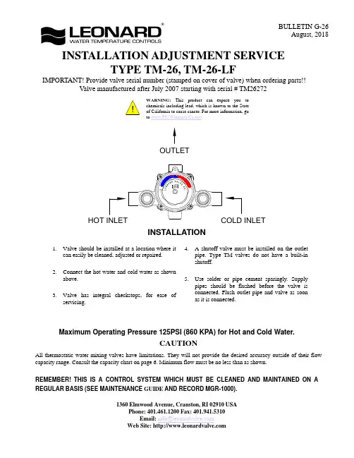
INSTALLATION ADJUSTMENT SERVICEADJUSTMENT AND SERVICEWARNINGThis mixing valve is equipped with an adjustable high temperature limit stop factory set at approximately 120°F (49°C)with an incoming hot water supply temperature of 150°F (65.5°C).If the hot water supply temperature of the job is greater than 150°F (65.5°C),the valves when turned to full HOT will deliver water in excess of 120°F (49°C)and the limit stops MUST BE RESET BY THE INSTALLER!TO RESET ADJUSTABLE HIGH TEMPERATURE LIMIT STOP:1.Loosen LTR Set Screw,remove POINTER SCREW.2.Adjust POINTER to maximum desired temperature.3.Remove POINTER,replace POINTER on spline rod withSTOP (which is cast into the underside on the pointer),resting against the BOTTOM side of the WEB on the FINE ADJUSTMENT SCREW.4.If fine adjustment is needed,adjust FINE ADJUSTMENTSCREW on the cover,loosen for hotter or tighten for cooler temperature.5.Replace POINTER and check temperature,if set to desiredtemperature replace POINTER SCREW,and tighten LTR SET SCREW.6.The new maximum temperature has now been set.Test thistemperature by holding a thermometer under the flow of water to be certain it is as desired.*LIMIT STOP MUST BE RESET AND RECHECKED EACH TIME HANDLE IS REMOVED.WARNINGWARNING!This Thermostatic Mixing Valve has an adjustable high temperature limit stop which,must be checked.If temperature is too high,the installer MUST RESET this stop immediately.Always check the temperature of the mixed water when the lever handle is turned to full HOT.Excessively hot water is DANGEROUS AND MAY CAUSE SCALDING!The high temperature limit stop is factory set at approximately 120°F (49°C)with an incoming hot water supply temperature of 150°F (65°C).If the incoming hot water on the job is higher than 150°F (65°C),the valve when turned to full hot will deliver water in excess of 120°F (49°C)and the high temperature limit stop MUST BE RESET BY THE INSTALLER.Check for significant variations in outlet flow.Thermostatic valves will NOT provide the desired accuracy outside of their flow capacity range.Minimum flows must be no less than shown (see Flow Capacities,page 6).If installed on a recirculated hot water system,make certain the valve is piped according to Leonard Required Piping Method #2(see page 4).REMEMBER!THIS IS A CONTROL DEVICE WHICH MUST BE CLEANED AND MAINTAINED ON A REGULAR BASIS.(SEE MAINTENANCE GUIDE AND RECORD,MGR-1000).WEBADJUSTMENT FINESCREW1017ASSE COLDHOT(REST STOP AGAINST SCREW)SET SCREWLTRSTOPPOINTER POINTER SCREWLeonard Type TM Thermostatic Water Mixing Valves are simple in design and may be easily cleaned,adjusted and repaired. If the installation is accessible, servicing may be completed without disconnecting the valve.NOTE:Thermostatic Water Mixing Valves are REGULATING mechanisms,which must be regularly maintained to provide best performance.Frequency of cleaning depends on quality of local water conditions and usage.(See Maintenance Guide and Record MGR-1000).REQUIRED METHODS OF PIPING TM V ALVES (RECIRCULATED HOT WATER SYSTEMS)METHOD #1METHOD #1Required when hot water supply is to be circulated to a master mixer or individual thermostatic mixing valves which are a substantial distance from the hot water source.It is used primarily in a building with several risers,with tempered water in each riser controlled by a separate master mixer.NOTE:The engineer must determine maximum distance which can be run,i.e.maximum allowable time for hot water to reach user with one shower head operating,based upon code requirements and/or good practice.METHOD #2METHOD #2setup INSTRUCTIONSBefore any attempt is made to adjust this system,be sure the temperature of the hot water at the source is properly set and maintained.1.Be sure system is piped in accordance with Method #2.2.Shut off circulator.3.Open enough fixtures to flow 2TO 4GPM.4.Set mixing valve to the desired temperature,(note Warning Tag attached to the pointer of the valve).5.Shut off all fixtures.Note:At this point,be sure NO water is being drawn through any fixture until the temperature in the recirculated line has been set.6.Open the balancing valve approximately 1/2way and start the circulator.Make sure no water is being drawn.7.Observe the temperature until it stabilizes.8.Close the ball valve slightly if the temperature is too hot,or open if it is too cold and again let the temperature stabilize.Repeat until the desired recirculated temperature is set.CIRCULATE HOT WATER FROM END OF LINE BACK TO TANK (THIS PIPING IS NOT TO BE USED FOR AN ENTIRE BUILDING!)HOT SUPPLY COLD SUPPLYBALL VALVETO FIXTURESTEMPERED WATER CTCHECK VALVEBALANCING VALVECIRCULATORAQUASTATTEMPERED FIXTURESTEMPERED RETURNHIGH TEMPERATURE RETURNCOLD SUPPLYHEAT TRAPCCIRCULATORTEMPERED BALL VALVE FOR SETUP (OPTIONAL)HIGH TEMPERATURE FIXTURES (IF APPLICABLE)CHECK VALVEISOLATION VALVEHOT WATER SOURCE(SEE NOTE BELOW)NOTE:FOR MULTIPLE TEMPERED LOOPS, A BALANCING VALVE AND CHECKVALVE MUST BE INSTALLED ON EACH LOOP AFTER TEMPERED FIXTURESTROUBLESHOOTING INSTRUCTIONSSee page 5 for Parts BreakdownsPACKINGS & GASKETS1.Leak at pointer rod.2.Leak between valve cover and base.PARTS REQUIRED:KIT#1/26(PACKINGS & GASKETS)PORT SLEEVE ASSEMBLY3.Valve delivers either all hot or all cold water, or will not mix consistently.KIT#R/28(REBUILDING KIT)OR TM-28-1-8B BRIDGE ASSEMBLY THERMOSTAT GROUP 4.After cleaning or replacing port sleeve assembly, valve will not hold temperature.KIT#R/28(REBUILDING KIT)OR TM28-G2THERMOSTAT GROUP CHECKSTOPS5.Hot water bypass into cold line.6.Supplies cannot be shut off completely.7.Leak at checkstop bonnet.KIT#4/M20(CHECKSTOP KIT)INSTRUCTIONS FOR DISMANTLING VALVE (DWG.1)1.Shut off hot and cold supplies to valve.2.Remove four Cover Screws M20-2C to release entire thermostatic control assembly.WHEN RE-ASSEMBLING VALVE ,insert Cover Gasket M20-3C in base.Lubricate TM28-6B O'Rings before re-inserting assembly.After installing new parts,it will may be necessary to reset high temperature limit.See instructions "TO RESET ADJUSTABLE HIGH TEMPERATURE LIMIT STOP"(page 2).TO REMOVE BRIDGE ASSEMBLY (DWG.2)Remove MU-10B Pointer Rod Nut,remove TM28-1-8B Bridge Assembly from pointer rod.Failure to properly blend the water may be caused by a sticking condition in the TGM-1/28Port Sleeve Assembly.The Thimble should slide freely on the Port Sleeve.Clean with a NON-CORROSIVE CLEANING AGENT AND SOFT CLOTH.DO NOT USE ABRASIVES,then wash parts thoroughly.To reassemble,replace Bridge Assembly on pointer rod.Driving ball on Thimble MUST engage hole in coil bracket.Replace pointer rod nut.DO NOT apply grease or lubricants to the TGM-1/28Port Sleeve Assembly.TO DISASSEMBLE BRIDGE ASSEMBLY (DWG.3)Remove TM25-3A Holder Nuts using a screwdriver in the slots provided.Clean or replace TGM-1/28Port Sleeve Assembly following instructions above.When reassembling,check TM-25-3B port sleeve packings and replace if necessary.TO CLEAN OR REPLACE THERMOSTAT GROUP Loosen gland nut.Push rod through cover.BE CAREFUL NOT TO PULL THERMOSTAT COIL OUT OF SHAPE.To clean,if a deposit has collected on the thermostat group,brush in a non-corrosive cleaning solution.Rinse in clean water and replace in cover with parts as shown.TM-26 V ALVE PARTSREMEMBER!THIS IS A CONTROL DEVICE WHICH MUST BE CLEANED AND MAINTAINED ON A REGULAR BASIS (SEE MAINTENANCE GUIDE AND RECORD).NOTE:AFTER INSTALLING NEW PARTS IT WILL BE NECESSARY TO RESET THE ADJUSTABLE HIGH TEMPERATURE LIMIT STOP ON EACH V ALVE (SEE PAGE 2).CHECKSTOP PARTSREPAIR KITSMU-5A UPPER CHECKSTOPSSTEM O'RINGM20-3A BONNETPACKINGAND PACKINGUPPER STEM CHECK SPRINGM20-6A LOWER STEM & PACKINGM20-9ACHECK BONNETM20-2A RF/CP MU-4A RF/CP (2 REQ'D)TGM-1/28BRIDGE(2 REQ'D)HOLDER NUT O'RINGTM28-6BTM25-5P.S. PACKING (2 REQ'D)PORT SLEEVE TM25-3B ASSEMBLYPOINTER ROD NUTM20-1C RF/CPP.S. HOLDER NUTMU-4CTM25-3ADIAL PLATE57-D COVERTM28-G2THERMOSTAT GROUP(2 REQ'D)TM25-3P.S. HOLDER MU-10BM20-3C GASKETCOVER 3307POINTER7628LTR SET SCREW6910POINTER SCREW7520RF/CP-CHOOSE ONE RF ROUGH FINISH CP CHROME FINISHM20-2CCOVER SCREWSGLAND NUTGLAND PACKING(2 REQ'D)TM28-1-8BBRIDGE ASSEMBLY& PKG. (2 EACH)KIT R/28 REBUILDING KITKIT 4/M20 CHECKSTOP KITCONTROL ASSEMBLYKIT 1/26 PACKINGS & GASKETSLOWER STEM O'RING (2 EACH)HOLDER NUT LOWER STEM & PACKINGBONNET PKG.2 EACH:M20-6A M20-3C GASKETCOVER (2 EACH)GLAND PKG.M20-3A(2 EACH)MU-4C STEM O'RINGMU-5A UPPER GASKETM20-3C COVER M20-3A BONNET PKG.TM28-1-12B THERMOSTATIC (2 EACH)O'RING MU-5A M20-6A TM28-6B CHECK SPRINGCHECK SPRINGM20-9AM20-9A(2 EACH)TEMPERED WATERTO BUILDINGBALL VALVE FULL LINE SIZE SYSTEMOUTLET OF HIGH-LOW PIPE TO OUTLET OF HIGH LOW SYSTEM(A)BALL VALVEOPTIONAL OUTLET SETUP PIPING(BY OTHERS)The addition of this piping arrangement (extra tee and ball valve)eliminates the need to turn showers on and off throughout the building at setup.The flows required in the setup instructions (page 3)are set by using Ball Valve A.(make sure main outlet ball valve is closed).CAUTION!ALL THERMOSTATIC WATER MIXING VALVES AND SYSTEMS HAVE LIMITATIONS!THEY WILL NOT PROVIDE THE DESIRED PERFORMANCE OUTSIDE OF THEIR FLOW CAPACITY RANGE!CONSULT THE CAPACITY CHART BELOW AND OBSERVE MINIMUM FLOWS SHOWN.FLOW CAPACITIES1360 Elmwood Avenue, Cranston, RI 02910 USAPhone: 401.461.1200 Fax: 401.941.5310LIMITED WARRANTYLeonard Valve Company (hereinafter,“Leonard”)warrants the original purchaser that products manufactured by Leonard will befree from defects in material or workmanship under normal conditions of use,when properly installed and maintained in accordance with Leonard’s instructions,for a period of one year from the date of shipment.During this period,Leonard will at its option repair or replace any product,or part thereof,which shall be returned,freight prepaid,to the Leonard factory and determined by Leonard to be defective in materials or workmanship.Leonard provides no warranty,express or implied,which extends beyond the description contained herein.LEONARD SPECIFICALLY DISCLAIMS ANY AND ALL IMPLIED WARRANTIES OF MERCHANTABILITY OR OF FITNESS FOR A PARTICULAR PURPOSE.Nonetheless,some jurisdictions may not allow the disclaimer of certain implied warranties,in which case Leonard hereby limits such implied warranties to the duration of the limited warranty period contained herein.Some jurisdictions may not allow limitations on how long an implied warranty lasts,so the foregoing durational limitation may not apply to you.In no event will Leonard be liable for labor or incidental or consequential damages.Any alteration or improper installation or use of this product will void this limited warranty.If any provision of this limited warranty is prohibited by law in the applicable jurisdiction,such provision shall be null and void,but the remainder of this limited warranty shall continue in full force and effect.TM-26MODELSYSTEM PRESSURE DROP 72192.130L\MINMAXIMUM FLOW CAPACITYFLOW MINIMUM (GPM)INOUT3/4"3/4"3.71.010*********131.026387.310.75764151.4171.7L\MINGPM BAR PSI 453540508087212.4232.89598253.1263.4。

4WRZE力士乐比例阀样本
一、结构
二、工作原理
4WRZE力士乐比例阀的工作原理是通过电磁线圈产生的磁场作用于阀芯,使阀芯在阀体内做上下运动,从而调节阀芯开口大小,进而调节流体流量。
电磁线圈接收到控制信号时,通过电流变化而改变磁场强度,从而实现对阀芯位置的精确控制。
三、特点
1.高精度:4WRZE力士乐比例阀采用先进的比例电磁阀技术,具有调节精度高的特点,可满足各种流量调节的要求。
2.双向控制:4WRZE力士乐比例阀可实现双向控制,能准确调节正反向流体的流量,并且切换迅速,无泄漏。
3.快速响应:4WRZE力士乐比例阀的电磁阀响应时间短,能快速调节流量,适应高速流体控制的需求。
4.高可靠性:4WRZE力士乐比例阀采用高质量的材料和先进工艺,具有耐腐蚀、耐高温、耐压等特点,保证了阀门在恶劣环境下的长期稳定运行。
5.节能环保:4WRZE力士乐比例阀能通过精确调节流量来实现能源的高效利用,降低系统能耗,并且采用无渗漏设计,避免了浪费和对环境的污染。
四、适用范围。

!DescriptionProportional valve (Electronic Pressure Regulator)with micro processor which enables you to adjust all parameters settings by means of push buttons.Features•Alarm Output Signal 24VDC when Required Pressure is Reached•Connector M12 4P Male (Plug and Cable are Not Supplied)•Fits in the Parker Pneumatic Frame-block (Air Service Unit)•Free Programmable Software•Integrated and Adjustable Slow-Start FunctionsAccuracyLinearity...................................................< 0.3% of F .SAir ConsumptionUnder normal conditions and in steady state there is no air consumption.Alarm Output SignalWithin the signal band an output signal is available:24VDC, PNP open collector, max 50mA, prevented against short-circuit (accepts inductive loads).Available OptionsAnalog Output:0 - 10 VoltsFor additional information, please contact factory.Change the Control SignalFrom 0 - 10 V to 4 - 20mA (Ri = 500.): (Parameter 4)EPDN SeriesProportional ValveWARNINGDo not adjust any of the other parameters. These are factorysettings. Any other change can have a big influence on the performance of the regulator.Parker Pneumatic does not warranty units which have not been properly used and / or adjusted.Class of Protection ...............................IP 65Control Signal0 - 10V , Ri = 100K or 4 - 20mA, Ri = 500The control signal can be changed.Dimensions: See page 18Electrical ConnectionsUse plug M12: 4-Pole female(Other connectors available on request)The electrical connections are as follows:Pin No.Function Color 124V SupplyBrown 20-10V Control signal Ri = 100kWhite 30V (GND)SupplyBlue 424VAlarm Output SignalBlackFlow Capacity:1/2" = 63.6 SCFM, 1" = 148.3 SCFM Hidden Functions EPDN4-MPDuring start-up unit. (Power goes on)When keys DOWN and UP are pressed during start-up, (connecting to the 24V power supply) manual mode is activated. This means that the user is able to increase / decrease the output pressure of the EPD,by pressing the UP or DOWN key. During this action the display will blink, indicating that the manual mode is activated.Pressing the UP and DOWN key againsimultaneously will cause the EPD to terminate manual mode.After Start-up (Power is on)Parameter 0 = 3Entering this value in parameter 0 will store the calibrated factory data into the working parameters.(Default calibration data is used)Behavior ControlThe regulation speed of the pressure regulator can be modified by means of one parameter. (P 20)The value in this parameter has a range from 0-5, a higher value means slower regulation speed (but more accurate). When the value 0 is entered, you are able to create your own custom settings. For details see page 12, parameter 20.Materials Housing......................Anodized Aluminum and PlasticSeals....................................................................NBRValves......................................................PolyurethaneOthers....................................Delrin, Brass, AluminumMountingThe unit preferably is to be mounted vertically with the electrical connection to the top.Parameters.Functonality of EPD can be manipulated by means of parameter settings. These settings can be changed by means of the 3 buttons at the front side of the EPD.For details see page 12 “How to Change Parameters”.Pilot Valve ProtectionWhen the required output pressure can not be achieved because of a lack of input pressure the unit will display “No.P”. The output pressure will then approximately be equal to the inlet pressure. As soon as the input pressure is back on the required level the normal control function follows.Pressure RangePrimary (Input Pressure):..........................max. 16 barSecondary (Output Pressure):.....................0 to 12 barThe output pressure is indicated on a built-in digital display. Pressure drop input / output min. 0,5 bar Response TimesFor a volume of 330 cm³ directly on the outlet of the regulator:Pressure increase from 2 to 4 bar.................32 msecsPressure increase from 2 to 8 bar...............137 msecsPressure decrease from 4 to 2 bar................64 msecsPressure decrease from 8 to 2 bar..............159 msecsFor a volume of 330 cm³ on a distance of 20 meters from the regulator (Connected with tubing -inner Ø 10 mm)Pressure increase from 2 to 4 bar.................56 msecsPressure increase from 2 to 8 bar...............200 msecsPressure decrease from 4 to 2 bar................69 msecsPressure decrease from 8 to 2 bar................96 msecsSupply Voltage..........................24V DC ± 10%Reverse Protected.....................Max. 200 mA. Safety ExhaustThe valve will force exhaust at a control signal below 0.1 volt or 4.2 Ma.SettingsThe regulator is pre-set at the factory as indicated on label. If required, adjustments can be made, seepage 12.Dead Band:..± 1% of FS (= ± 0 to12 bar) = Hysteresis Proportional Band:...............±10% of FS (= ± 1,2 bar) Signal Band:.........................±10% of FS (= ± 1,2 bar)Specific ApplicationsSo far the EPD has been used in a wide variety of applications such as:1.Regulating welding forces on spot weld guns.2.Regulating protective gases in laser cuttinginstallations.3.Maintaining pressure in cutting head chamberson tunnel drilling equipment.4.Maintaining a small overpressure in clean rooms.5.Regulating air-humidity in storage and handlingrooms for e.g. tobacco or wood.6.Regulating sprays of paint through the nozzles ofpainting installations.7.Maintaining a protective shield of inert gases infurnaces in steel mills to avoid the contaminationwith air of gas in the metal.8.Adjusting of braking forces on ships winches.9.Adjusting governors on marine diesel engines.10.Blowing plastic of glass bottles.11.Controlling specific gas mixtures in laboratories.12.Regulating speed control on a roll of carpetwhilst rolling up in order to maintain the samestretch through the entire cloth.13. Controlling vacuum in tube expansion purposes.Temperature Range...................14°F to 122°F(-10°C to 50°C) Type......................................................EPDN Working MediumCompressed air or inert gases, filtered to min. 40µ, lubricated or non-lubricated, once lubricated air is supplied, this must be maintained.Parameter Setting ChangeableStandard User SettingValue Description Unit Action Resultparameters*000N/A1N/A2N/A3Back to factory settings Back to NormalSettings 401mA Set Setpoint Input to mA0(4)-20mA, (P29) 1V Set Setpoint Input to volt0-10V 600Alarm Output Set Output to Digital Alarm Output24V= In Band 1Analog Output Set Output to Analog Output0-10V~P_out 880 to 120100% F.S.Set Analog Output Span Span = 0-11V 1250 to 250100x 10 mbar Set Proporitonal Area0,5 to 2,5 bar13 2 to 4015x 10mbar Set Deadband Area20 to 400 mbar1400bar Change Display Reading bar 1PSI PSI15 1 to 2501x 10 mbar Set Slow Area0 to 2,5 bar1615*****Set Slow Steps Highest Speed to 20Lowest Speed 180 to 2000x 10 mbar Set Preset Pressure (x10 mbar)0 to 2 bar 190 to 100100 % F.S.Pressure Correction0 to P-max 200Custom Set Set Behavior Control P 12,13, 21 1Fastest Adjustable2Fast Only with33Normal0 Custom Set4Slow5Slowest21510Set Proportional Value Fastest Regulation to 100Slowest Regulation *Other parameter settings are available. Consult factory.How to Change Parameters:Pressing Accept key for more than 3 sec, will activateparameter change mode. User can select parameterby pressing up or down key on EPD. (display showsPxx). When parameter number is correct, pressingaccept again will enter parameter number. (displayshows parameter value now). Pressing the up or downkey will change the parameter. (blinking display pointshows parameter editing mode). Pressing the acceptkey will accept the new parameter value. (all digits willblink during acception). After releasing all keys , thenext parameter number will be presented on thedisplay. When no key is pressed, after 3 sec thedisplay will show the actual output pressure.Ordering-key SpecialsTypePassage Flow RateConnections SCFM Internal Thread 412 mm 63.61/2" BSPP 512 mm 63.61/2" NPT 825 mm 148.31" BSPP 925 mm148.31" NPTEPDN 4M 0145P 0U 10CMinimum Maximum MicroPressure Pressure Control Type ProcessorControlControlSignalOptionPressure Control-required minimum pressure,expressed in B bar of M mbar or PSI (preset pressure)-required maximum pressure (=F .S.*),expressed in B bar of M mbar or PSI (max. 12 bar or 174 PSI)Control Signal0U100 ± 10 VDC, Ri = 100 kohm 4I 20 4 ± 20 mA, Ri = 500 ohm 8BIT 8 Bit DigitalB bar P PSIOptionBlank No Option C Slow Start Function DSuitable for OxygenWelding Products EPDN Dimensions。
nz200t-22gy-4说明书型号:NZ200T-22GY-4说明书一、产品概述NZ200T-22GY-4是一款高性能的工业用电磁阀,主要用于控制气体或液体的流通。
其采用先进的电磁阀技术和材料,具有结构牢固,操作可靠,使用寿命长的特点。
本说明书将对该产品的结构、性能、安装和维护等方面进行详细介绍。
二、主要技术参数1. 工作电压:AC220V/50Hz2. 工作压力范围:0-1.6MPa3. 工作介质温度:-10℃~80℃4. 阀体材质:铸铁5. 密封材料:NBR (丁腈橡胶)6. 进出口口径:G1/47. 防护等级:IP65三、产品结构NZ200T-22GY-4电磁阀由以下主要部件组成:1. 阀体:采用高强度铸铁材料,经过精密加工,具有良好的耐腐蚀性能。
2. 阀芯:采用耐高温材料制造,结构紧凑,可靠性高。
3. 电磁线圈:采用绝缘材料包裹,保证了安全可靠的电气接触。
4. 密封件:采用耐油耐酸碱性能好的NBR橡胶制成,有效防止泄漏。
5. 其他配件:包括固定螺丝和垫圈等。
四、使用环境要求1. 温度范围:-10℃~60℃。
2. 湿度范围:相对湿度不大于85%。
3. 周围环境无可燃气体或腐蚀性气体,无强烈振动和冲击。
4. 安装位置应平稳,并与输送介质方向一致,防止堵塞。
五、安装与使用1. 产品应由专业技术人员安装,并确保阀体与管路连接牢固、不漏气。
2. 在使用前,请仔细检查阀体和密封件是否完好,如有损坏需及时更换。
3. 接通电源后,可通过观察电磁线圈上的指示灯来判断电磁阀是否正常工作。
4. 操作该电磁阀时,应根据实际需要合理控制通电时间和通电频率。
5. 在长时间不使用时,应切断电源,并进行定期维护,清洁阀体和密封件。
六、维护与保养1. 常规维护:定期检查并清洁阀体和密封件,确保无杂质和泄漏。
2. 寿命维护:根据使用情况,及时更换耐磨损的部件,以延长电磁阀的使用寿命。
3. 定期检查电磁线圈的绝缘性能,如发现有损坏或老化的情况,需要及时更换。
美国BESWICK针阀工作原理说明工作原理说明:BESWICK针阀是一个可调节的孔,可用于控制流速,微型气缸,喷嘴,定时回路,加注头,放气孔以及许多其他应用。
调整后的流量即使在温度波动期间也保持稳定,因为针阀和阀座均由不锈钢制成。
工作压力范围: NV的最大入口压力为500 psig。
金属对金属的密封提供了正向关闭功能,可关闭至25 in Hg。
美国BESWICK针阀是一种微调阀,其阀塞为针形,主要用作调节气流量。
微调阀要求阀口开启逐渐变大,从关闭到开启最大能连续细微地调节。
针形阀塞即能实现这种功能。
针形阀塞一般用经过淬火的钢制长针,而阀座是用锡、铜等软质材料制成。
阀针与阀座间的密封是依靠其锥面紧密配合达到的。
阀针的锥度有1:50和60锥角两种,锥表面要经过精细研磨。
阀杆与阀座间的密封是靠波纹管实现的。
防腐方法:首先阀体的防腐蚀,主要选用材料为不锈钢,碳钢。
虽然防腐蚀的资料十分丰富,但能否选得恰当,还是不容易的事情,因为腐蚀的问题很复杂。
选择阀体材料的难处,还在于不能只考虑腐蚀问题,同时必须考虑耐压耐温能力,经济上是否合理,购买是否容易等因素。
其次是采取衬里措施,如衬铅、衬铝、衬工程塑料、衬天然橡胶及各种合成橡胶等。
如介质条件许可,这倒是一种节约的方法。
再次,在压力、温度不高的情况下,用非金属做阀门主体材料,往往能十分有效地防制腐蚀。
此外,针型阀阀体外表面还受到大气腐蚀,一般钢铁材料都以刷漆来防护。
有效节流孔:标准针:0英寸至0.032英寸(0-0.8毫米)。
50psig时约0-1 SCFM气流。
高分辨率针:0英寸至0.032英寸(0-0.8毫米)。
50 psig时约0-1 SCFM气流。
这种配置特别适合控制低流速。
高流量针:0英寸– 0.059英寸(0-1.5毫米)。
在50psig下约有0-3 SCFM 气流。
Cv值图调节:所有版本均配有2-56螺纹调节螺钉。
使用指定的标准针,调节螺钉从完全打开到完全关闭大约2.25圈。
2Parker Hannifin Corporation Hydraulic Valve DivisionElyria, Ohio, USASubplate Mounted Direct Operated Relief Valve Series RASBulletin HY14-3025-M13/USBul HY14-3025-M13.indd, ddpTechnical InformationValve Size Bolt Kit ChartBolt Size *Qt'y Torque to:RAS600BK041/2-20x1 3/4 LG413 Ft. Lb.* Use SAE grade 8 bolts or betterBolt Kit Chart© 2015 Parker Hannifin Corporation. All rights reserved.FAILURE OR IMPROPER SELECTION OR IMPROPER USE OF THE PRODUCTS DESCRIBED HEREIN OR RELA TED ITEMS CAN CAUSE DEA TH, PERSONAL INJURY AND PROPERTY DAMAGE.• This document and other information from Parker-Hannifin Corporation, its subsidiaries and authorized distributors provide product or system options for further investigation by users having technical expertise.• The user, through its own analysis and testing, is solely responsible for making the final selection of the system and components and assuring that all performance, endurance, maintenance, safety and warning requirements of the application are met. The user must analyze all aspects of the application, follow applicable industry standards, and follow the information concerning the product in the current product catalog and in any other materials provided from Parker or its subsidiaries or authorized distributors.• To the extent that Parker or its subsidiaries or authorized distributors provide component or system options based upon data or specifications provided by the user, the user is responsible for determining that such data and specifications are suitable and sufficient for all applications and reasonably foreseeable uses of the components or systems.WARNING – USER RESPONSIBILITYThe items described in this document are hereby offered for sale by Parker-Hannifin Corporation, its subsidiaries or its authorized distributors. This offer and its acceptance are governed by the provisions stated in the detailed “Offer of Sale” elsewhere in this document or available at /hydraulicvalve.OFFER OF SALEFor safety information, see Safety Guide SG HY14-1000 at /safety or call 1-800-CParker.SAFETY GUIDEBulletin HY14-3025-M13/US, 9/15Supersedes: September 15, 2003 Parker Hannifin CorporationHydraulic Valve Division520 Ternes AvenueElyria, Ohio 44035 USATel: 440-366-5100Fax: 440-366-5253/hydraulicvalve。
USER MANUALFORBATH SENSING MODULE V7 Doc. Ref. 4601598 ver. 1.16Last Modified: 5 March 2012Copyright Parker Hannifin Corporation 2012. Confidential and Proprietary. All Rights Reserved.Copying of this document and distributing it to others, or the use or communication of the contents thereof, is forbidden without prior written authorization. The copyright notice hereon shall not constitute or imply publication.This manual provides basic details of the Bath Sensing Module V7 and includes a fault finding guidelines in case of problems.Contents:Page subject3 Installation and Warning notices4…6Specifications7 Dimensions8…9Connection overview10 Bath Sensing Module wiring proposal11…12 Fuses13…14Indicators15 Power Up Sequence16…19 Error handling20 DeclarationsTo access and check for the latest version then go to: -Installation Manual -http://literature/Pneumatics Division Europe/PDE-Documents/BSM-V7_Installation_Manual-UK_4601598.pdfQuick reference guide - http://literature/Pneumatics DivisionEurope/PDE-Documents/BSM-V7_Quick_Ref_Installation_Manual-UK_4601594.pdfInstallation and Warning NoticesThis device is intended for industrial use only.WarningWarningSPECIFICATIONS(all values measured at room temperature unless otherwise noted)Power supply(pin 16 vs. pin 15) 24V +/-10%Current consumption(pin 16 vs. pin 15) max. 65mA(excluding PNP signals ) Inrush current @ 23 ºC(pin 16 vs. pin 15) max. 300mAInternal thermal 24V fuse rating0,75 / 1,50 A @ 23 ºC0,41 / 0,82 A @ 70 ºC(hold current / trip current)Optional Input(pin 11 vs. pin 15) min. 22 V / max. 28 V Current consumption @24V(pin 11 vs. pin 15) max. 6mAChisel in bath, PNP Output (pin 14 vs. pin 15) PNP, 24VPNP current sourcing capabilities(pin 14 vs. pin 15) max. 100mA 1) 2)Chisel in bath, NPN Output(pin 10) NPN, max. 30VNPN current sinking capabilities(pin 10) max. 100mA 3) (ifmoreoutputcurrentisneeded,*******************************)SPECIFICATIONS (continued)Status Signal, PNP Output(pin 13 vs. pin 15) PNP, 24VPNP current sourcing capabilities(pin 13 vs. pin 15) max. 100mA 1) 2)Status Signal, NPN Output(pin 9) NPN, max. 30VNPN current sinking capabilities(pin 9) max. 100mA 3) (ifmoreoutputcurrentisneeded,*******************************)Maximum chisel current(pin2/4 vs. pin6/8) 25mAMaximum chisel withstand-voltage(pin2/4 vs. pin6/8) >750VMaximum sensing range(pin2/4 vs. pin6/8) >8,5V 4) Temperature range0 … 70 ºCMinimum isolation voltage between>3,0kVDC continuous. cathode referenced and 0V (PLC) referencedsides of the PCBMinimum physical separation on PCB6,3 mmbetween cathode- and 0V-GND planes.Dimensions 12 x 10 x 2,4 cmSPECIFICATIONS (continued)Notes:1) Although the PNP output driver is self-limiting in case of a short circuit, it is recommended to limit the short circuit duration to a minimum. During a short circuit the PNP output led will be OFF. Initial short circuit peak current is 0,9A+. Theoretically this peak, in combination with high ambient temperature, could also trip the thermal main fuse inside the module. Solving the short circuit and turning the module off for 20 seconds will get it working again.2) In case of applying 24V to the Chisel in bath and/or Status signal outputs, in combination with reversed power supply wiring, the applied reverse current should not exceed 200mA. Otherwise the output driver might be damaged.3) Although the NPN output driver disables itself in case of a short circuit, it is recommended to limit the short circuit duration to a minimum amount of time. During a short circuit the NPN output led will remain ON because the led is connected to the PNP driver only. The NPN driver will enable itself again during the next cycle providing that the short circuit is removed. Initial short circuit peak current is neglectable.4) Sensing range is equal to the maximum bath voltage (including wiring and fuse losses!) the Bath Sensing Module is able to respond to, when supplied with 24,0V. When the module is supplied with the specified minimum voltage (24-10% = 21,6V), the sensing range might decrease with 0,1…0,25 volt.DIMENSIONSCONNECTION OVERVIEWPIN 01 NOT CONNECTED, PLEASE DON’T USE.PIN 02 C HISEL (SPARE CONNECTION)PIN 03 NOT CONNECTED, PLEASE DON’T USE.PIN 04 CHISEL (PIN 02 and PIN 04 are internally connected)PIN 05 NOT CONNECTED, PLEASE DON’T USE.PIN 06 CATHODEPIN 07 NOT CONNECTED, PLEASE DON’T USE.PIN 08 CATHODE (PIN 06 and PIN 08 are internally connected)PIN 09 STATUS OUTPUT NPNPIN 10 CHISEL IN BATH OUTPUT NPNPIN 11 OPTIONAL INPUT (24V)PIN 12 DATA-LOG-OUT *)PIN 13 STATUS OUTPUT PNPPIN 14 CHISEL IN BATH OUTPUT PNPPIN 15 0V POWER SUPPLYPIN 16 +24V POWER SUPPLYNotes:- Do not use the spare PIN 02 (or PIN 04) to loop a chisel wire to next module!Every chisel wire should have its own Bath Sensing module.- One of both cathode pins (PIN 06 or PIN 08) can be used to loop the cathodewire to the next module(s). Looped cathode wires should be from one pot only.Never connect cathode wires from different pots together.- PIN 12 (data-log-output) is only to be used by authorized employees. Data-log PIN 12 should be connected to measurement systems with proper galvanic isolation. Multi-meters and laptops (without charger!) are preferred!CONNECTION OVERVIEW (continued)BATH SENSING MODULE WIRING PROPOSALFUSESGeneral infoMost smelters use one chisel fuse per breaker and one common cathode fuse per pot to fuse the Bath Sensing modules. These fuses can have a huge impact on Bath Sensing performance. In terms of Bath Sensing performance, the main fuse characteristic that is important to observe is the ohmic resistance of the fuse.Unfortunately most fuse manufacturers don’t specify ohmic resistance in their datasheets. However, a reasonable indication of fuse resistance can be calculated with data that is usually provided in datasheets: voltage drop is namely the product of current through the fuse, times the fuse resistance. Thus the fuse resistance can be calculated with:[ fuse resistance = max. voltage drop / nominal current ]Fuse selectionTo reach optimum Bath Sensing performance aim to select fuses that have a resistance between 0 and 15 Ohms.Sometimes it might be required to choose a fuse with a higher rated current than normally would have been chosen solely based on the chisel current ( max 25mA / nominal 12mA ) ExampleThe following examples are referring to the datasheet of SIBA fuses on the next page.32mA fuse => resistance = 4500mV / 0,032mA = 141 Ω100mA fuse => resistance = 1500mV / 0,100mA = 15 Ω125mA fuse => resistance = 17000mV / 0,125mA = 136 Ω1A fuse => resistance = 1200mV / 1A = 1,2 Ω2A fuse => resistance = 800mV / 2A = 0,4 ΩExclusively seen from Bath Sensing performance viewpoint, the 1A and 2A fuses would be the best fuses to select.FUSES (continued)Disclaimer:This chapter FUSES only gives an overview of the process for meeting the essential fuse resistance requirements for optimal Bath Sensing performance. The customer always remains ultimately responsible for the safety and compliance of the whole system to regulations applying to pot rooms.INDICATORSINDICATORS (continued)RED = STATUS signalThe red STATUS led has two functions:- During normal use, the red led will flash every few seconds to indicate a certain firmware calculation has ended successfully.- When an internal error is discovered by the firmware, the red STATUS led will light up continuously.If the chisel [PIN2/4] and cathode [PIN6/8] pins are shorted deliberately, i.e. for testing purposes, the red led might come up (in combination with yellow CHISEL IN BATH led). As long as both led’s turn off again after the short circuit is removed, there is nothing wrong with the module.YELLOW = Chisel in Bath signalYellow led will light up when the module senses the chisel is in contact with the bath.GREEN = Power supply indicator- When the green led is continuously ON, all (internal) power supplies are working within specifications.- If the chisel [PIN2/4] and cathode [PIN6/8] pins are shorted deliberately, i.e. for testing purposes, the green led might turn off (in combination with CHISEL IN BATH and/or S TATUS led’s both on). As long as the green led turns on again after the short circuit is removed, there is nothing wrong with the module.ORANGE = Optional InputOrange led will light up when the optional input [PIN11] is enabled. Please note that this function is not mandatory for proper function. Do not connect this input without consulting Parker.NOTE:Two pot meters are visible between the yellow and green led’s.Please do not change the settings of these pot meters without consulting PARKER.POWER UP SEQUENCEDuring the first 60 seconds after powering up the Bath Sensing module, this Power Up Sequence analyzes the chisel voltage, temperature influences etc. to improve accuracy especially during pot-start up.Although the firmware is able to filter out one crust breaking cycle (including physical contact between chisel en bath) during this Power Up Sequence, it is recommended to prevent bath contacts for the first 60 seconds after powering on the module, i.e. by temporarily opening the chisel fuse. In case more Bath Sensing modules are powered up at once, opening the cathode fuse would be the most convenient way to prevent disturbing the Power Up Sequence.Please note that the Bath Sensing Modules will NOT respond to any bath contactsduring the Power Up Sequence at all!To notify the Power Up Sequence is running, the red and green led’s are used as following: •Green led flashes every other second. (1 seconds off / 1 second on) •Red led flashes every 6 seconds for 10msec. (5,99 seconds off / 10msec on)10 times in total during “power up” sequence.When the green led is continuously on, the Power Up Sequence is finished and normal Bath Sensing function will start.ERROR HANDLINGGREEN led is OFF (or blinking irregularly):- Check the +24V power supply. [PIN15 vs PIN16]- If 24V is available and stable, open the chisel fuse and then remove the +24V supply.[PIN16] - Wait 1 minute before reconnecting the +24V supply [PIN16].- If the green led starts blinking with one second interval (indicating the Power Up Sequence is running) wait until the green led is on continuously before closing the chisel fuse.(Please see the chapter “Power Up” Sequence”)If the green led refuses to light up whilst the 24V power supply is available and the chisel fuse is opened, disconnect the wiring and exchange the module. Contact PARKER.YELLLOW CHISSEL IN BATH led stays OFF:Make sure the chisel is physically capable of reaching the bath by performing a manual stroke. Bath liquid should be visible on the chisel upon retraction. Bath Sensing ca n’t perform its function when bath level is beyond the chisel’s mechanical reach!If the bath is within the mechanical reach of the chisel, please reset the module by following the procedure below.RESET PROCEDURE- Open the chisel fuse and turn the module off by disconnecting the +24 Volt [PIN16]- Wait 1 minute.- Turn the module ON again by reconnecting [PIN16]. (with chisel fuse still opened!)- If the green led starts blinking with one second interval (indicating the Power Up Sequence is running) wait until the green led is on continuously.END RESET PROCEDUREERROR HANDLING (continued)After the RESET the red led should flash every 2 or 3 seconds.Use a multi-meter to measure chisel/cathode voltage directly on the Bath Sensing module between [PIN2/4 and PIN6/8] with the chisel fuse still open.V7 modules shou ld read somewhere between 9,3…10 VDC. Keep in mind that the reading might not be stable due to inducted voltages on the wiring. In case the reading seems way off, disconnect both cathode and chisel wires from the module and measure again directly on [PIN2/4 and pin6/8]. Reading should be stable and within range now. If not, exchange the module and contact Parker.When the reading is within range, make sure the cathode and chisel wiring is reconnected and close the fuses.- Connect a multi-meter to the chisel [PIN2/4] and to the cathode [PIN6/8].- Monitor the measured DC voltage (if possible use MIN/MAX function of the multi-meter) whilst performing a manual crust breaking stroke including a few seconds in maximum extended position.- The lowest (MIN)stable* voltage should be close (±1V) to the pot voltage. The lower the better. If the measured voltage is way above this range, check the wiring, fuse holders and chisel/cathode fuse resistance. (see chapter FUSES)Stable* = as long as the chisel is not in contact with the bath, the measured voltage might be unstable due to induction voltages. However, when the chisel is in fully extended position dipped into the bath, a more stable voltage should be readable.If the measured chisel-cathode voltage is within ±1V of the pot voltage, but the module does not respond with a Chisel In Bath output, open the cathode and chisel fuses and disconnect both chisel and cathode wires.- Use a multi-meter to measure between 0V [PIN15] and data-log [PIN12]. With open chisel and cathode contacts, the multi-meter should read between 3,8 and 5,0 VDC.- Short circuit the chisel [PIN2/4] and cathode [PIN6/8] pins directly on the module.- The multi-meter should read a significantly lower voltage now, usually below 1V.In very hot conditions, the RED led might turn on during the short circuit. This is normal behavior. Observe the yellow bath-contact led, it should turn ON during the short circuits between chisel and cathode. If the led does not respond, exchange the module or disconnect the wiring and contact PARKER.ERROR HANDLING (continued)YELLLOW CHISEL IN BATH led stays ON:- Open the chisel fuse. [PIN2/4]- The Chisel in Bath output and the corresponding yellow led should turn off.- If not, perform the RESET procedure:RESET PROCEDURE- Open the chisel fuse and turn the module off by disconnecting the +24 Volt [PIN16]- Wait 1 minute.- Turn the module ON again by reconnecting [PIN16]. (with chisel fuse still opened!)- If the green led starts blinking with one second interval (indicating the Power Up Sequence is running) wait until the green led is on continuously before going to the next step.END RESET PROCEDUREIf the yellow Chisel in Bath led turns on again after power-up (and/or during the Power Up Sequence), exchange the module and contact PARKER.If the led stays off, close the chisel fuse and monitor the module’s performance during a few strokes.RED led is ON continuously:- Open both chisel and cathode fuses.- Perform the RESET procedure.If the red led stays off, close the chisel and cathode fuses and monitor the module’s performance during a few strokes.If the red led lights up again continuously, exchange the module and contact PARKER.ERROR HANDLING (continued)ALL LED’S ARE BLINKING FAST:Probably the internal thermal fuse is tripping. Try to determine if there is a heat source from outside the module that is heating up the Bath Sensing Module. (i.e. a super structure door is left open)Try to perform th e RESET procedure below. However, if the led’s keep blinking fast even after cooling down for a longer period of time, there might be hardware damage. In that case exchange the module and contact Parker.RESET PROCEDURE- Open the chisel fuse and turn the module off by disconnecting the +24 Volt [PIN16]- Wait 1 minute.- Turn the module ON again by reconnecting [PIN16]. (with fuses still opened!)- If the green led starts blinking with one second interval (indicating the Power Up Sequence is running) wait until the green led is on continuously before going to the next procedure. END RESET PROCEDUREClose the cathode and chisel fuses and monitor the module’s performance.For any other unmentioned error or erratic behavior of the Bath Sensing Module:Please contact PARKER.EMC and ROHS Declarations for the Bath Sensing Module.。
PneumaticCatalog 0637-4/USA“B” SeriesAir Control ValvesB2 -.16 Cv M5, 1/8" Port B3 -.75 Cv 1/8", 1/4" Port B4 - 1.22 Cv 1/4" PortB5 - 1.40 Cv 1/4", 3/8" Port B6 - 2.70 Cv 3/8" Port B7 - 5.90 Cv 1/2" Port B8 -7.00 Cv3/4" PortIndexWARNINGFAILURE OR IMPROPER SELECTION OR IMPROPER USE OF THE PRODUCTS AND/OR SYSTEMS DESCRIBED HEREIN OR RELATED ITEMS CAN CAUSE DEATH, PERSONAL INJURY AND PROPERTY DAMAGE.This document and other information from Parker Hannifin Corporation, its subsidiaries and authorized distributors provide product and/or system options for further investigation by users having technical expertise. It is important that you analyze all aspects of your application including consequences of any failure, and review the information concerning the product or system in the current product catalog. Due to the variety of operating conditions and applications for these products or systems, the user, through its own analysis and testing, is solely responsible for making the final selection of the products and systems and assuring that all performance, safety and warning requirements of the application are met.The products described herein, including without limitation, product features, specifications, designs, availability and pricing,are subject to change by Parker Hannifin Corporation and its subsidiaries at any time without notice.Offer of SaleThe items described in this document are hereby offered for sale by Parker Hannifin Corporation, its subsidiaries or its authorized distributors. This offer and its acceptance are governed by the provisions stated on the separate page of this document entitled “Offer of Sale”.© Copyright 2001, Parker Hannifin Corporation. All Rights Reserved!IndexTable of Contents Air Control ValvesBasic Valve Functions4-Way Valves (2)3-Way Valves (3)Common Part Numbers ......................................................................................... 4-5 Model Number IndexesB2 Series (6)B3 Series (7)B4 Series (8)B5 Series (9)B6 Series (10)B7 & B8 Series (11)IEM Stackable ManifoldsManifolds & Kits (12)Ordering Information (13)Bar ManifoldsIEM Bar Manifolds (14)Subbase Aluminum Bar Manifolds (15)Ordering Information (16)AccessoriesSubbase & Manifolds (17)Sandwich Regulators (18)Featured Valve Options ...................................................................................... 19-20 Electrical Connectors / Accessories .................................................................. 21-22 Technical InformationTechnical Data (23)Solenoid Data (24)Pilot Configuration (25)Repair InformationSolenoid Kits (26)Exploded Views ............................................................................................. 28-33 Dimensions ........................................................................................................ 34-52 Definitions & Weights .. (53)Offer of Sale (56)Operator / Function 7#14Operator / Function 0CE#14APBSingle Solenoid4-Way, 2-PositionDe-energized position – Solenoid operator #14 de-energized.Pressure at inlet port 1 connected to outlet port 2.Outlet port 4 connected to exhaust port 5.Energized position – Solenoid operator #14 energized.Pressure at inlet port 1 connected to outlet port 4.Outlet port 2 connected to exhaust port 3.Double Solenoid4-Way, 2-PositionSolenoid operator #14 energized last. Pressure at inlet port 1connected to outlet port 4. Outlet port 2 connected to exhaust port 3.Solenoid operator #12 energized last.Pressure at inlet port 1connected to outlet port 2. Outlet port 4 connected to exhaust port 5.Single Remote Pilot4-Way, 2-PositionNormal position – Pressure at inlet port 1 connected to outlet port 2. Outlet port 4 connected to exhaust port 5.Operated position – Maintained air signal at port 14.Pressure at inlet port 1 connected to outlet port 4.Outlet port 2 connected to exhaust port 3.Double Remote Pilot 4-Way, 2-PositionMomentary air signal at port 14 last. Pressure at inlet port 1connected to outlet port 4. Outlet port 2 connected toexhaust port 3.Momentary air signal at port 12 last. Pressure at inlet port 1connected to outlet port 2. Outlet port 4 connected to exhaust port 5.Double Solenoid4-Way, 3-PositionDouble Remote Pilot4-Way, 3-PositionDual Pressure:May be used for dual pressure service with pressure at ports 3 & 5. (Use either external pilot source option “K”, “W” or “X”, or dual pressure pilot source option “D” or “E”.) If pilot source “D” or “E” is selected, the high pressure must be at port #3. If pilot source “K”, “W” or “X” is selected, the external pilot must be plumbed to port #14 or “X” respectively. NOTE: The “B6” valve is also available with dual pressure using Port 5 for high pressure (Option “G” & “H”). This is only to be used if converting from a “42” (“CM”) Series traditional valve.In the 3-Position valve, the effect of dual pressure is extremely important when the valve is in the center position, as the CEand PC functions are reversed. Therefore, care should be used when selecting a 3-Position valve.4-Way Valve FunctionsBasic Valve Functions#14#12#12#14#12With #12 operator signaled – inlet port 1 connected tocylinder port 2, cylinder port 4 connected to exhaust port 5.With #14 operator signaled – inlet port 1 connected tocylinder port 4, cylinder port 2 connected to exhaust port 3.Function 8: All Ports BlockedAll ports blocked in the center position.Function 9: Center ExhaustCylinder ports 2 and 4 connected to exhaust ports 3 and 5 in center position. Port 1 is blocked.Function 0: Pressure CenterPressure port 1 connected to cylinder ports 2 and 4, and exhaust ports 3 and 5 blocked in center position.With #12 operator energized – inlet port 1 connected to cylinder port 2, cylinder port 4 connected to exhaust port 5.With #14 operator energized – inlet port 1 connected to cylinder port 4, cylinder port 2 connected to exhaust port 3.Function 5: All Ports BlockedAll ports blocked in the center position.Function 6: Center ExhaustCylinder ports 2 and 4 connected to exhaust ports 3 and 5 in center position. Port 1 is blocked.Function 7: Pressure CenterPressure port 1 connected to cylinder ports 2 and 4, and exhaust ports 3 and 5 blocked in center position.#12#10Single Solenoid3-Way, 2-Position NCNormally Closed:De-energized position – Solenoid #12 de-energized.Pressure at inlet port 1 blocked, outlet port 2 connected to exhaust port 3.Energized position – Solenoid #12 energized.Pressure at inlet port 1 connected to outlet port 2,exhaust port 3 is blocked.Single Solenoid3-Way, 2-Position NONormally Open:De-energized position – Solenoid #10 de-energized. Pressure at inlet port 1 connected to outlet port 2,exhaust port 3 is blocked.Energized position – Solenoid #10 energized.Pressure at inlet port 1 blocked, outlet port 2 connected to exhaust port 3.Double Solenoid3-Way, 2-PositionSolenoid operator #12 energized last.Pressure at inlet port 1connected to outlet port 2, exhaust port 3 is blocked.Solenoid operator #10 energized last. Pressure at inlet port 1blocked, outlet port 2 connected to exhaust port 3.Single Remote Pilot 3-Way, 2-Position NCNormally Closed:Normal position – Pressure at inlet port 1 blocked,outlet port 2 connected to exhaust port 3.Operated position – Maintained air signal at port 12.Pressure at inlet port 1 connected to outlet port 2,exhaust port 3 is blocked.Single Remote Pilot3-Way, 2-Position NONormally Open:Normal position – Pressure at inlet port 1 connected to outlet port 2, exhaust port 3 is blocked.Operated position – Maintained air signal at port 10.Pressure at inlet port 1 blocked, outlet port 2 connected to exhaust port 3.Double Remote Pilot3-Way, 2-PositionMomentary air signal at port 12 last. Pressure at inlet port 1connected to outlet port 2, exhaust port 3 is blocked.Momentary air signal at port 10 last. Pressure at inlet port 1blocked, outlet port 2 connected to exhaust port 3.3-Way Valve / Dual 3/2 Valve FunctionsBasic Valve FunctionsDual 3-WayCombines the functions of T wo 3-Way valves into One valve body . The valve can be configured as Two Normally Closed 3-Way FunctionsTwo Normally Open 3-Way FunctionsOne Normally ClosedANDOne Normally Open 3-Way Functions42531#14#1242531#14#1242531#14#12#12#10#12#10#12#10#12#10#12Solenoid, 3-Way & 4-WayCommon Part NumbersSingle Solenoid4-Way, 2-PositionDouble Solenoid4-Way, 2-PositionSingle Solenoid3-Way, 2-Position, NCDouble Solenoid4-Way, 3-Position,APB3-Pin DIN 43650C Electrical Connection,Non-Locking Flush Override.InlineInlineInlineInline#12B3 thru B8B2 OnlyInternal Air Return Spring / Air Return#14B3 thru B8B2 OnlyInternal Air Return Spring / Air Return#12#10#12APB#12Remote Pilot, 3-Way & 4-WayCommon Part NumbersSingle Remote Pilot4-Way, 2-PositionDouble Remote Pilot4-Way, 2-PositionSingle Remote Pilot3-Way, 2-Position, NCDouble Remote Pilot4-Way, 3-Position, APBInlineInlineInlineInlineB3 thru B8B2 OnlyB3 thru B8B2 OnlyInternal Air Return Spring/Air ReturnInternal Air ReturnSpring/Air Return#12#10Basic Operator/Port Size/Pilot Source/Enclosures/EngineeringBasic Operator/Port Size/Pilot Source/Enclosures/EngineeringBasic Operator/Port Size/Pilot Source/Enclosures/EngineeringBasic Operator/Port Size/Pilot Source/Enclosures/EngineeringBasic Operator/Port Size/Pilot Source/Enclosures/EngineeringBOLD OPTIONS ARE STANDARDBasic Operator/Port Size/Pilot Source/Enclosures/EngineeringB7 & B8 SeriesIEM Stackable ManifoldsEnd Plate KitsTransition Plate Kit•Combines B3 and B5 4-Way valves into a common inlet and exhaust manifold system. Looking at the #12 end, the B5 is on the right and the B3 is on the left.•Kit includes: B3 end plate, B3/B5 transition plate, B5 end Kit includes: Right and Left End Plate, o-rings, socket head cap screws, flat washers and lockwashers.* B4 & B5 4-Way use the same Kit.ManifoldsIEM Stackable Manifolds & KitsStation Station Station Station 1234Example:Application requires a 4-station manifoldwith flow controls and requires isolationbetween station 2 & 3 for all three main galleys.Qty.Part No.Comment1AAB3FC04041B32FBD553C ..............Station 11B31FBE553C ..............Station 21PS2919P .....................Galley 1, 3, 5Between Station 2 & 31B31FBB553C ..............Station 31B35FBB553C ..............Station 414 End12 EndLooking at 12 EndIEM Stackable Add-A-Fold AssembliesOrdering InformationXXT otal Number of StationsNumber of Flow Controlbases in assembly (Omit if none)3-Way Valve B34-Way Valve 3-Way Valve B44-Way Valve B54-Way ValveAAAdd-A-Fold AssemblyHow To Order IEM Stackable Add-A-Fold Assemblies1.List Add-A-Fold Assembly call out.This automatically includes the end plate kit,manifold bases and assembly.2.List complete inline valve model number,listing left to right LOOKING A T THE #12 END of the manifold. The left most station is station 1.(If a blank station is needed, list theBlank Plate part number at the desired station.)*Flow control bases must start at station 1 in Add-A-Folds.Example: AAB3FC0206. Station 1 & 2 have flow controls, station 3 – 6 do not.B3B4B5B5 SeriesIEM Bar Manifolds (Inlet / Exhaust Manifold)Bar Manifolds35mm DIN 4-Way3-Way4-Way3-Way4-Way3-Way4-Way3-WayCylinder Port # of Model NumberSubbase Aluminum Bar Manifolds (5-Ported)Bar Manifolds•Utilizes Subbase mount B2 valves.•3-Way & 4-Way valves interchangeable.•External Pilot Valves – “X” or “W”, must be used.•Common External Pilot galley is field convertible from Internal to External Pilot.(Shipped as Internal Pilot from factory.)35mm DIN Rail MountInternal ExternalKit includes:Subbase –(1) manifold (bolts & gasket comewith subbase valve).•Utilizes Subbase mount B3 valves.•Available for 4-Way valves. If 3-Way function is required,plug a cylinder port.•Common External Pilot galley is standard.•Standard Internal Pilot valves need not use this galley,and the galley does not need to be plugged.•External Pilot Valves – “X” or “W”, must have Common External Galley pressurized.35mm DINHow To Order Aluminum Bar Manifold Assemblies1.List Manifold Assembly call out. Use AA +the part number of the aluminum bar manifold.This automatically includes the aluminum bar manifold and assembly.2.List complete valve model number, listing left toright, LOOKING AT THE #12 END of the manifold.The left most station is station 1.(If a blank station is needed, list the blanking plate part number at the desired station.)#12 End#14 EndExample:Application requires a 3-station “B3”3-Way manifold with station #1 blankedoff with valves assembled.Qty.Part No.Comment1AAPSG3BXN03NP1PS2966P .....................Station 11B330000XXC...............Station 21B3J0BB553C...............Station 3Station Station Station 123Looking at 12 EndAluminum Bar Manifold AssembliesOrdering InformationUse Aluminum Bar Manifold Kit Numbers from previous pages.Manifold AssemblySubbase / ManifoldsAccessoriesSubbaseBlanking PlateKit includes: (2) Screws, (2) Nuts, (2) ClampsDIN Rail Hardware Kit。
金子KANEKO电磁阀是如何衍变过来的又有什么功能金子KANEKO电磁阀是如何衍变过来的又有什么功能呢KANEKO电磁阀在泥沙和杂物较多的一些工况(如黄河水质,污水处置系统等),阀门掌控管路简单被堵塞,导致阀门失灵;大的杂物很简单把阀板卡住,导致阀门密封不严;还有一些特别工况,阀门启闭时水锤很大,导致阀门启闭时响声巨大,甚至造成事故。
KANEKO电磁阀采纳先进的流体设计,能耗低、运行稳,密封效果好,它兼具电动闸阀、电动蝶阀以及止回阀的功能,快捷的快关速度和可调的泄压时间,能有效除去水锤危害,保护水泵及管网系统安全。
管力阀适用于自动化给KANEKO电磁阀站的离心泵、真空泵、混流泵和轴流泵出水管道,设计有膜片式与活塞式两种掌控装置,可分别适用于清水、原水类介质和污水、渣浆水类介质。
产品类型上,开发有一般型、回水低压型、污水型等五种规格,以充足不同工况需求。
的基础上研制而成,是水泵掌控阀的换代新产品。
它兼具电动闸、电动蝶阀以及止回阀的功能,并通过快关和缓闭的动作来除去水锤危害,保护水泵及管网系统安全。
该阀是当前国内外结构最新奇、性能、进行的泵站新型掌控设备,重要用于自动化给排水泵站的离心泵、冶金、石化、水利、市政、环保等行业供排水系统。
金子KANEKO电磁阀本阀门由阀体,橡胶管套、大小阀杆闸板、上下导柱等零件构成。
金子KANEKO电磁阀工作原理:管力阀在泥沙和杂物较多的一些情况下(如黄河水质,污水处置系统等),阀门掌控管路简单被堵塞,导致阀门失灵;大的杂物还简单把阀板卡住,导致阀门密封不严;还有一些特别情况,阀门开关时水锤很大,导致阀门开关时响声巨大,甚至造成事故。
我公司自成立以来,一直致力于水泵出口掌控阀的研制与生产,为能解决这些问题。
膜片式管力阀是水泵出口继老式手动掌控阀、液控蝶阀、多功能水力阀与液力自动阀等掌控阀门后的第五代新产品。
通过对金子KANEKO电磁阀的流体设计,形成直线型流道,能耗低、运行稳,密封效果好,它兼具电动闸阀、电动蝶阀以及止回阀的功能,通过提高快关时间,能更好地除去水锤危害,保护水泵及管网系统安全。
◆ S kinner kinner((美国产美国产))系列比例调节电磁阀系列比例调节电磁阀((介质介质::空气空气、、中型气体中型气体))BP 系列对于复杂问题提供简单而有可靠的解决方案对于复杂问题提供简单而有可靠的解决方案,,不像普通嗲你擦只能进行简单的开关控制的开关控制,,BP 阀科一从0到最大值之间比例的控制KV 值。
电磁执行部分根据输入信号进行定位根据输入信号进行定位,,位置的变换汇控制流过的流量位置的变换汇控制流过的流量。
应用应用::质量流量控制器制器--医疗器械医疗器械,,尤其是氧气呼吸机尤其是氧气呼吸机。
分析仪表及仪器仪表分析仪表及仪器仪表,,实验仪器核试验室内室内。
功能功能::固态电子优化功能固态电子优化功能。
无摩擦运动保证几百万次无故障无摩擦运动保证几百万次无故障,,无噪音工作无噪音工作。
不锈钢结构钢结构,,幅橡胶动态蜜蜂幅橡胶动态蜜蜂,,丁晴橡胶静态密封丁晴橡胶静态密封。
体积紧凑体积紧凑,,满足大多的应用满足大多的应用。
尤其适合与开环或闭环系统。
Parker Skinner 电磁阀系列电磁阀系列1/8” A126LB13001 A12LB13002 71211SN1MM0071221SN1MM00A116LB13001 A11LB130021/8” 71235SN1AN00 71235SN1EN0071235SN1GN0071235SN1KN0071235SN1MN001/4” 71235SN2AN00 71235SN2EN0071235SN2GN0071235SN2KN0071235SN2MN00Flange 7121FBF4GF00 7121FBF4NF001/8” 71216SN1FU00 71216SN1BL00 71216SN1GL00 7121KBN1GF00 71215SN1EF00 3121BBN1AN00 3121BSN1AN00 71215SN1GF00 7121KBN1LR00 71216SN1JT00 3121BBN1EN003121BSN1EN00 3121BSA6EN00 71215SN1EN00 B2*1400 7121KBN1NF00 71215SN1GN00 3121BBN1GN003121BSN1GN00 3121BSA6GN0071215SN1KN00C2*1277 71215SN1KF00 B2*1250 C2*1251 71215SN1MF0071215SN1MN00 3121BBN1JN00 3121BSN1JN00 B2*1175 3121BBN1LN00 3121BSN1LN00 3121BSA6LN00 C2*1132 C2D420CF71215SN1QN003121BBN1NN003121BSN1NN001/8” C2*1092 C2*1081 Male 71215SN1SN00 C2*1062 Male 71214LE1MN00 B2*1052C2*10513121BBN1QN003121BSN1QN003121BSA6QN0071215SN1VN00Male 71214LE1QN00B2*1026C2*1031Male 71214LE1SN001/4”71216SN2FU00 71216SN2GL00 7121KBN2GR00 7121KBN2GF00 71215SN2EF007121KBN2JR0071215SN2GF007321HBN2SN007121KBN2LR00 71216SN2JT00 71215SN2EN00 7121KBN2NF00 7121KBN2NR00 71215SN2GN00 73212BN2MN00 73212SN2MN00 7321KBY61640 71215SN2KN00 71215SN2KF00 71215SN2MF00 71215SN2MN00 7321KBN2RN00 7121KBN2NV00 7121KBN2QV00 71215SN2QN00 7121KBN2SV00 71215SN2SN00 71214VN2KN00 71214VN2KT00 71214TN2KT00 71214VN2MN00 71214VN2MT00 71214TN2MT00 71215SN2VN00 71214VN2QN00 71214VN2QT00 71214TN2QT00 71214VN2SN00 71214VN2ST00 71215SN21N00 71214TN2ST00 71216SN2BL00 73216BN2MT00 73216SN2MT00 3/8”7221GBN3VN00 73218BN3TN00 7321KBN3SN00 7321KBN3SNW0 72218BN3TN00 72218RN3TV00 Barb71214LT3KN007121KBN3UV00Barb 71214LT3MN00Barb71214LT3QN00Barb71214LT3SN0071215SN33N0071215SN33NHP 7321HBN3TN00 73212BN3SN00 7321KBY63200 1/2” 7321HBN4UN00 73212BN4TN00 7321KBY6320A 7221GBN4VN00 73218BN4UN00 7321KBN4SN00 7321KBN4SNW0 72218BN4UN00 72218RN4UV00 7121KBN44V00 A2LB4017 A26LB40063/4” 73212BN52N00 7321GBN53N00 7321GBN53NMC 7221GBN51N00 7221GBN51NC0 73218BN5VN00 72218BN5VN00 72218RN5VV00 XLG2O760 XLG2O6001” XLG2O1060 73212BN63N00 7321GBN64N00 7321GBN64NMC 7221GBN61N00 7221GBN61NC0 7221GBN64N00 7221GBN64NC0 73218BN64N00 LB27BB6127 LB27B110 XLG2O103011/4” 7321GBN76N00 7321GBN76NMC 73218BN75N00 LB27BB7127 LB27B1201 1/2” 73218BN87N00 7321GBN88N00 7321GBN88NMC LB27BB8127 LB27B130 XLG2O15302” 7321GBN99N00 7321GBN99NMC1/8” 71225SN1EF00 7122KBN1GF00 7122KBN1PR00 71225SN1GF00 71295SN1ENJ1 B11*1400 71295SN1GNJ1 3129BBN1AN00 3129BSN1AN00 71295SN1KNJ1 B11*1200 3129BBN1EN00 3129BSN1EN00 7122KBN1LF00 71225SN1KF003129BBN1GN00 3129BSN1GN00 3129BBN1JN00 3129BSN1JN00 B11*1040 3129BSN1LN00 3129BBN1LN001/4” 71225SN2EF00 7322HBN2SV00 7122KBN2GF00 71225SN2GF00 71295SN2ENJ1 73222BN2MN00 71295SN2GNJ1 71225SN2KF00 7122KBN2LF00 73222SN2MN00 71295SN2KNJ1 3/8” 7322HBN3TN00 73222BN3SN00 73228BN3TN00 72228RN3TV00 72228BN3TV001/2” 7322HBN4UN00 73228BN4UN00 73222BN4TN00 72228RN4UV00 72228BN4UV003/4” 7322GBN53N00 7322GBN53NC0 73222BN52N00 73228BN5VN00 72228BN5VV00 72228RN5VV001”7322GBN64N00 7322GBN64NC0 73222BN63N00 73228BN64N001 1/4” 7322GBN76N00 7322GBN76NC0 73228BN75N001 1/2” 7322GBN88N00 7322GBN88NC0 73228BN87N002” 7322GBN99N00 7322GBN99NC01/4”7321KBN2RE00 7121KBN2SE00 7321KBN2RES0 7121KBN2SES0 3/8” 73218BN3TE00 7321KBN3SE00 7221GBN3VE00 73218BN3TTS0 72218BN3TE00 72218RN3TE00 72218RN3TES0 7321KBN3SES0 73218BN3TES0 7221GBN3VES0 72218BN3TES0 1/2” 73218BN4UE00 7321KBN4SE00 7221GBN4VE00 73218BN4UTS0 72218BN4UE00 72218RN4UE00 7221GBN4VES0 72218BN4UES0 7321KBN4SES0 73218BN4UES0 72218RN4UES0 3/4” 73218BN5VE00 7221GBN51E00 73218BN5VTS0 72218BN5VE00 72218RN5VE00 73218BN5VES0 72218BN5VES0 72218RN5VES0 7221GBN51ES01” 7221GBN61E00 7221GBN64E00 73218BN64E00 73218BN64TS0 7221GBN61ES0 73218BN64ES0 7221GBN64ES0 11/4” 73218BN75E00 73218BN75TS0 73218BN75ES0 11/2” 73218BN87E00 73218BN87TS0 73218BN87ES0 3/8” 73228BN3TTS0 72228BN3TE00 72228RN3TE00 72228BN3TES0 72228RN3TES01/2” 73228BN4UTS0 72228BN4UE00 72228RN4UE00 72228BN4UES0 72228RN4UES03/4” 73228BN52TS0 72228BN5VE00 72228RN5VE0072228BN5VES0 72228RN5VES01” 73228BN64TS011/4” 73228BN75TS0 11/2” 73228BN87TS0。