瑞典保加玛(programma)TM1600 MA61断路器机械特性测试仪
- 格式:doc
- 大小:63.00 KB
- 文档页数:3
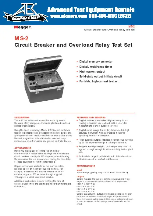
MS-2Circuit Breaker and Overload Relay Test SetsDigital memory ammeter sDigital, multirange timer sHigh-current outputsSolid-state output initiate circuit sPortable, high-current test setMS-2Circuit Breaker and Overload Relay Test SetDESCRIPTIONThe MS-2 test set is used around the world by severalthousand utility companies, industrial plants and electrical service organizations.Using the latest technology, Model MS-2 is a self-contained test set that incorporates a variable high-current output and appropriate control circuitry and instrumentation for testing thermal, magnetic or solid-state motor overload relays;molded-case circuit breakers; and ground-fault trip devices.APPLICATIONSModel MS-2 is capable of testing the time-delaycharacteristics of motor overload relays and molded-case circuit breakers rated up to 125 amperes, when following the recommended test procedure of testing the time delay of these devices at three times their rating.Higher currents are available for the short durations required to test an instantaneous trip element. For example, the test set will provide a maximum short-duration output of 750 amperes through a typical, 125 ampere, molded-case circuit breaker.Additional applications include verifying the ratio ofcurrent transformers and testing panelboard ammeters and voltmeters.FEATURES AND BENEFITSs Digital memory ammeter:High-accuracy, direct-reading instrument has read-and-hold memory for measurement of short-duration currents.sDigital, multirange timer:Crystal-controlled, high-accuracy instrument with autoranging measures operating time to 1 millisecond.sHigh-current output:Provides instantaneous currents up to 750 amperes through a 125 ampere breaker.sRugged and lightweight:Unit weighs only 33 lb (15kg) and is tough enough to withstand daily field or plant use.sSolid-state output initiate circuit:Solid-state circuit eliminates need for contact maintenance.SPECIFICATIONSInputInput Voltage (specify one):120 V OR 240 V , 50/60 Hz, 1f OutputOutput Ranges:The output is continuously adjustable in four ranges to accommodate a variety of test-circuit impedances:0 to 5 A at 120 V max. 0 to 25 A at 24 V max.0 to 120 A at 6 V max. 0 to 240 A at 3 V max.Output Capacity:The output circuit is designed to permit short-duration overloads and the output ranges will provide severaltimes their current rating, provided the output voltage is sufficient to push the desired current through the impedance of the test circuit.1981MS-2 Circuit Breaker and Overload Relay Test SetThe test set is capable of testing the time-delay characteristics of devices rated up to 125 A using a test current of three times their rating (375 A). Additionally, to perform an instantaneous trip test, it will provide 750 A through a typical, 125 A, molded-case circuit breaker connected with the test leads provided with the test set. Overload Capability:T o increase use of the test set, it is designed so that the current ratings may be exceeded for short durations. Because the magnitude of the output current is determined by the impedance of the load circuit, the voltage rating must be sufficient to push the desired current through the device under test and the connecting test leads.Percent Rated Maximum MinimumCurrent Time On Time Off100 (1x)30 min30 min200 (2x) 3 min8 min300 (3x)30 s 4 min400 (4x)7 s 2 minOutput Initiate Circuit:The test set uses a solid-state output initiating circuit. T o increase reliability and eliminate contact maintenance, this circuit uses a triac instead of a contactor to initiate the output.The initiating circuit provides momentary and maintained modes to control output duration. The momentary mode is used whenever the output is to be on for a short duration, such as when performing instantaneous trip tests, or to avoid damage or overheating of the device under test while setting the test current. In the maintained mode, the output remains energized until manually turned off or, when performing timing tests, until the device under test operates — which both stops the timer andde-energizes the output.INSTRUMENTATIONAmmeterOperating Modes (switch-selected)MemoryNormalDisplay31/2digit, extra-bright LED display with 0.3 in. (7.62mm) numerals Ranges (switch-selected)0 to 1.999/19.99/199.9/750 A ContinousAccuracy (overall ammeter system)±1% of reading, ±1 digit on three high rangesRegulating:±1% of range, ±1 digit on low rangeTimerDisplay5-digit, extra-bright, LED display with 0.3 in. (7.62mm) numerals Ranges (switch-selected)0 to 99.999 s0 to 999.99 s0 to 99999 cyclesAccuracy±0.005% of reading, ±1 digitTimer Control CircuitThis circuit automatically starts the timer when the output is energized and automatically stops the timer and de-energizes the output when the device under test operates. This circuit accommodates the following test conditions by simple switch selection of the appropriate mode:Current Actuated:Used to test a device that has no auxiliary contacts to monitor, such as a single-pole circuit breaker. The timer stops when the output current is interrupted.Normally Closed:Used to test a device with normally closed contacts. The timer stops and the output is de-energized when the contacts open.Normally Open:Used to test a device with normally open contacts. The timer stops and the output is de-energized when the contacts close.EnclosureThe test set is housed in a high strength, molded, suitcase-type enclosure with carrying handle and removable cover. Storage space is provided for test leads.Dimensions9.9 H x 14 W x 11 D in.(25 H x 35 W x 28 D cm)Weight33 lb (15 kg)UKArchcliffe Road Dover CT17 9EN EnglandT +44 (0) 1304 502101 F +44 (0) 1304 207342UNITED STATES4271 Bronze WayDallas TX75237-1088 USAT 800 723 2861 (USA only)T +1 214 330 3203F +1 214 337 3038OTHER TECHNICAL SALES OFFICESValley Forge USA, Toronto CANADA,Mumbai INDIA, Trappes FRANCE,Sydney AUSTRALIA, Madrid SPAINand the Kingdom of BAHRAIN.Registered to ISO 9001:2000 Reg no. Q 09290Registered to ISO 14001 Reg no. EMS 61597MS2_DS_en_V10Megger is a registered trademark。
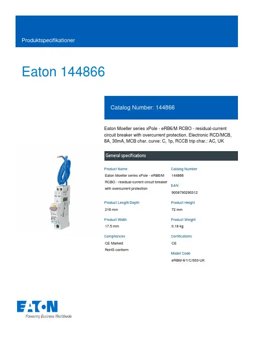
Eaton 144866Eaton Moeller series xPole - eRB6/M RCBO - residual-current circuit breaker with overcurrent protection. Electronic RCD/MCB, 8A, 30mA, MCB char. curve: C, 1p, RCCB trip char.: AC, UKGeneral specificationsEaton Moeller series xPole - eRB6/M RCBO - residual-current circuit breaker with overcurrent protection1448669008790290312216 mm 72 mm 17.5 mm 0.18 kg CE Marked RoHS conformCE eRBM-8/1/C/003-UKProduct NameCatalog Number EANProduct Length/Depth Product Height Product Width Product Weight Compliances Certifications Model Code8 AIs the panel builder's responsibility. The specifications for the switchgear must be observed.Meets the product standard's requirements.Is the panel builder's responsibility. The specifications for the switchgear must be observed.3Does not apply, since the entire switchgear needs to be evaluated.Meets the product standard's requirements.0 kA50/60 HzIs the panel builder's responsibility.10.03 A40 °C0 W69.5 mm1 mm²DA-DC-03_eRBIL019095ZUeaton-xpole-combined-mcb-rcd-device-rcbo-packaging-manual-multilingual.pdfMA120500735.pdfeaton-xpole-erb6-rcbo-catalog-ca019049en-en-us.pdfeaton-xpole-erb6-au-rcbo-catalog-ca019052en-en-us.pdfRated operational current for specified heat dissipation (In) 10.11 Short-circuit rating10.4 Clearances and creepage distances10.12 Electromagnetic compatibilityCurrent limiting class10.2.5 Lifting10.2.3.1 Verification of thermal stability of enclosures Rated short-circuit breaking capacity (EN 60947-2) Frequency rating10.8 Connections for external conductorsNumber of poles (total)Fault current ratingAmbient operating temperature - maxHeat dissipation per pole, current-dependentBuilt-in depthConnectable conductor cross section (solid-core) - min 10.9.3 Impulse withstand voltage Certifikater InstallationsvejledningKatalogerIs the panel builder's responsibility.Number of polesSingle-poleAmbient operating temperature - min-25 °C10.6 Incorporation of switching devices and componentsDoes not apply, since the entire switchgear needs to be evaluated.10.5 Protection against electric shockDoes not apply, since the entire switchgear needs to be evaluated.Equipment heat dissipation, current-dependent2 W10.13 Mechanical functionThe device meets the requirements, provided the information in the instruction leaflet (IL) is observed.10.2.6 Mechanical impactDoes not apply, since the entire switchgear needs to be evaluated.10.9.4 Testing of enclosures made of insulating materialIs the panel builder's responsibility.Static heat dissipation, non-current-dependent0 WApplicationSwitchgear for residential and commercial applications10.3 Degree of protection of assembliesDoes not apply, since the entire switchgear needs to be evaluated.Voltage typeACNumber of poles (protected)1Leakage current typeACRated short-circuit breaking capacity (EN 61009-1)10 kAOperating ambient temperature - min-25 °CHeat dissipation capacity0 WRelease characteristicCWidth in number of modular spacings1Power loss2 W10.2.3.2 Verification of resistance of insulating materials to normal heatMeets the product standard's requirements.10.2.3.3 Resist. of insul. mat. to abnormal heat/fire by internal elect. effectsMeets the product standard's requirements.Rated short-circuit breaking capacity (EN 61009)10 kAOperating ambient temperature - max40 °CVoltage rating240 V - 240 V10.9.2 Power-frequency electric strengthIs the panel builder's responsibility.Connectable conductor cross section (solid-core) - max25 mm²Degree of protectionIP20Overvoltage categoryIIIPollution degree210.7 Internal electrical circuits and connectionsIs the panel builder's responsibility.Connectable conductor cross section (multi-wired) - min1 mm²Rated impulse withstand voltage (Uimp)4 kV10.10 Temperature riseThe panel builder is responsible for the temperature risecalculation. Eaton will provide heat dissipation data for the devices.Basic functionCombined RCD/MCB devicesRated current8 AConnectable conductor cross section (multi-wired) - max25 mm²TypeRCBO10.2.2 Corrosion resistanceMeets the product standard's requirements.Surge current capacity0.25 kA10.2.4 Resistance to ultra-violet (UV) radiationMeets the product standard's requirements.10.2.7 InscriptionsMeets the product standard's requirements.Rated short-circuit breaking capacity (IEC 60947-2)0 kADisconnection characteristicUndelayedProduct applicationSwitchgear for industrial and advanced commercial applicationsRated operational voltage (Ue) - max240 VRated insulation voltage (Ui)500 VEaton Corporation plc Eaton House30 Pembroke Road Dublin 4, Ireland © 2023 Eaton. Alle rettigheder forbeholdes. Eaton is a registered trademark.All other trademarks areproperty of their respectiveowners./socialmedia。

断路器测试仪说明书由于输入输出端子、测试柱等均有可能带电压,在插拔测试线、电源插座时,会产生电火花,小心电击,避免触电危险,注意人身安全!安全要求请阅读下列安全注意事项,以免人身伤害,为了避免可能发生的危险,只可在规定的范围内使用。
只有合格的技术人员才可执行维修。
—防止火灾或人身伤害使用适当的电源线。
只可使用专用并且符合规格的电源线。
正确地连接和断开。
当测试导线与带电端子连接时,请勿随意连接或断开测试导线。
注意所有终端的额定值。
为了防止火灾或电击危险,请注意所有额定值和标记。
在进行连接之前,请阅读使用说明书,以便进一步了解有关额定值的信息。
使用适当的保险丝。
只可使用符合规定类型和额定值的保险丝。
避免接触裸露电路和带电金属。
有电时,请勿触摸裸露的接点和部位。
请勿在潮湿环境下操作。
请勿在易爆环境中操作。
-安全术语警告:警告字句指出可能造成人身伤亡的状况或做法。
目录一、介绍 (5)二、面板介绍 (7)三、仪器操作说明 (10)四、开关接线案例 (14)五、注意事项 (19)第一部分:介绍1.1概述HTGK-H 高压开关测试仪以单片机为核心进行采样,处理和输出,其主要特点是采用汉字提示以人机对话的方式操作,汉字显示结果并打印输出,具有智能化、功能多、数据准确、抗干扰性强、操作简单、体积小、重量轻、外观美等优点,适用于各种户内、户外少油、多油开关、真空开关、六氟化硫开关的动特性测试。
1.2主要测试项目及功能1.12个断口的固有分、合闸时间;2.重合闸时间;3.分、合闸最大不同期性;4.刚分、刚合速度;5.弹跳时间及幅度;6.开关开距及开关超行程(真空开关预置开关行程);7.分、合闸平均速度;8.显示、打印速度—距离曲线1.3 主要技术指标1.时间测量同时可测量断口数:≤12个测定过程整定时间:0—6秒分辨率:0.1ms2.开关开距、开关超行程、弹跳幅度测量量程:< 1000mm分辨率:1mm3.测量误差时间测量误差:±1%行程测量误差:±1%.4、速度测量范围:0—20m/s5.内置电源输出电压:20V—230V 误差:1%6.工作条件工作电压:AC220V±10 %频率:50Hz功耗:≤60w使用环境温度:0~40︒C使用环境湿度:≤90%RH体积:400⨯350⨯200 mm3重量:7kg1.4 术语定义刚分、刚合速度:动静触头刚分后、刚合前10ms触头运动的平均速度(为油开关定义)。

断路器测试仪的用途短路发生器:这是一种特殊的设计,具有很低的电抗,以便使断路器测试仪(又称高压开关动特性测试仪)具有最大的短路输出。
通过减小槽的深度和线圈末端的长度,可以降低漏电抗。
将端子带到可以进行不同连接的板上。
相中的每个绕组均分为两半,可以串联或并联连接。
三个绕组又可以星形或三角形连接,以提供不同的端子电压。
由于涉及巨大的电动势,发电机基础经过特殊设计,并通过软木,氯丁橡胶和热油等材料隔离,以防止振动传递到建筑物的其他部分。
绕组也经过特殊支撑和加固。
短路发生器具有闭路空气冷却。
断路器测试仪由轴流风扇和空气/水冷却器组成。
发电机由通过弹性轴连接的三相感应电动机驱动。
发电机配备有内置飞轮,可在机组短路和调速时提供动能。
脉冲励磁:尽管主发电机配备了阻尼绕组,但通常的励磁是由耦合至测试仪的主励磁机提供的,但仍可提供脉冲励磁或超励磁来抵消电枢反应的消磁作用。
滞后功率因数的短路电流具有消磁作用。
这导致总场的减小,因此导致感应电动势的减小。
结果,恢复电压小于短路前的电压。
通过在短路前一瞬间使发电机励磁电路中的电阻短路将其克服,从而使励磁电流激增至其正常值的8到10倍。
这样可以解决短路电流的消磁作用,并提供所需的恢复电压。
先导发电机:这是一个小型三相同步发电机,直接连接到短路发电机的主轴上,并与后者同相同步。
在短路测试期间,任何当前电压都由自动电压调节器保持恒定。
该可靠的电压是向顺序计时器,电磁示波器和进行测试的各种其他驱动电路提供控制电源所必需的。
短路变压器:这些变压器设计用于承受反复的短路,并且其绕组通常按分段布置,以串联和并联组合方式进行电压调节。
短路变压器的漏电抗保持在较低水平。
为了将电压降低至较低值,通常使用三相变压器。
对于高于生成电压的电压,通常的做法是使用单相变压器组。
根据要在测试单元中执行的测试类型,将不同类型和额定值的变压器连接到不同的单元中,例如,一个中的高压测试变压器,另一个中的低压大电流变压器。

iRelay 60综合保护测控装置用户说明书危险和警告本设备只能由专业人士进行安装,对于因不遵守本手册的说明所引起的故障,厂家将不承担任何责任。
重要提示感谢您使用深圳市中电电力技术股份有限公司的产品。
为了安全、正确、高效地使用本装置,请您务必注意以下重要提示:1) 本说明书仅适用于iRelay 60综合保护测控装置。
2) 请仔细阅读本说明书,并按照说明书的说明设置、测试和操作。
如有随机资料,请以随机资料为准。
3) 为防止装置损坏,严禁带电插拔装置各插件、触摸印制电路板上的芯片和器件。
4) 请使用合格的测试仪器和设备对装置进行试验和检测。
5) 装置如出现异常,请及时与本公司售后技术服务(400-8860-418)联系。
6) 本装置的设置缺省密码是:0000。
本说明书版权属深圳市中电电力技术股份有限公司所有,未经书面许可,不得复制,传播或使用本文件及其内容,违犯者将要对损坏负责。
深圳市中电电力技术股份有限公司保留所有版权。
我们已经检查了本手册关于描述硬件和软件保持一致的内容。
由于不可能完全消除差错,所以我们不能保证完全的一致。
本手册中的数据将定期审核,并在新一版的文件中做必要的修改,欢迎提出修改建议。
以后版本中的变动不再另行通知。
目录1 装置简介 (1)1.1 概述 (1)1.2 产品特点 (1)1.3 基本功能 (2)2 技术指标 (3)2.1 工作环境条件 (3)2.2 额定参数 (3)2.3 准确度 (3)2.4 遥信分辨率 (4)2.5 过载能力 (4)2.6 继电器输出 (4)2.7 开关量输入 (4)2.8 电气绝缘性能 (4)2.9 机械性能 (5)2.10 电磁兼容性能 (5)3 功能说明 (6)3.1 保护功能 (6)3.1.1 辅助元件 (6)3.1.2 大电流闭锁保护 (9)3.1.3 相电流充电保护 (10)3.1.4 相电流加速保护 (10)3.1.5 开入加速相电流保护 (11)3.1.6 速断保护 (11)3.1.7 限时速断保护 (12)3.1.8 过流保护 (13)3.1.9 过负荷保护 (14)3.1.10 反时限过流保护 (14)3.1.11 电压速断保护 (15)3.1.12 电压限时速断保护 (16)3.1.13 IN充电保护 (17)3.1.14 IN加速保护 (17)3.1.15 IN过流保护 (18)3.1.16 IN反时限过流保护 (19)3.1.17 I0充电保护 (19)3.1.18 I0加速保护 (20)3.1.19 I0过流保护 (20)3.1.20 I0反时限过流保护 (21)3.1.21 负序过流保护 (21)3.1.22 负序反时限保护 (22)3.1.23 电流不平衡保护 (22)3.1.24 过电压保护 (22)3.1.25 低电压保护 (23)3.1.28 VX低压保护 (25)3.1.29 高周保护 (25)3.1.30 低周保护 (26)3.1.31 功率保护 (26)3.1.32 同期检查 (27)3.1.33 重合闸功能 (29)3.1.34 绝缘监视 (31)3.1.35 起动间隔保护 (31)3.1.36 TV断线监视 (32)3.1.37 TA监视 (32)3.1.38 控制回路监视 (32)3.1.39 有效值过压保护 (33)3.1.40 有效值过流保护 (33)3.1.41 电动机运行状态判断 (34)3.1.42 起动时间过长保护 (35)3.1.43 过热保护 (35)3.1.44 tE时间保护 (36)3.1.45 堵转保护 (36)3.1.46 负荷丢失保护 (37)3.1.47 再起动功能 (37)3.1.48 起动次数保护 (38)3.1.49 开关量保护 (39)3.2 测量功能 (39)3.2.1 一次值 (39)3.2.2 二次值 (39)3.2.3 计量数据 (40)3.3 遥信功能 (40)3.4 控制功能 (40)3.5 通信功能 (40)3.6 记录功能 (41)3.6.1 事件记录 (41)3.6.2 故障录波记录 (42)3.6.3 波形瞬态捕捉功能 (42)3.6.4 起动报告功能 (43)3.7 对时功能 (43)4 操作使用说明 (47)4.1 装置前面板 (47)4.2 按键操作 (47)4.3 信号指示灯 (48)4.4 装置上电 (48)4.5 默认显示界面 (48)4.6 事件报告显示 (49)4.7 菜单说明 (49)4.7.3 定值设置 (53)4.7.4 报告管理 (59)4.7.5 装置维护 (61)4.7.6 装置调试 (62)4.7.7 定值清单 (62)5 安装调试说明 (74)5.1 安装 (74)5.1.1 装置安装图 (74)5.1.2 背板端子布置 (75)5.2 时钟电池 (78)5.3 通电试验 (78)5.4 投运前调试 (78)5.5 装置故障分析 (80)6 接线原理图 (82)6.1 装置接线示意图 (82)7 售后服务承诺 (87)7.1 装置升级 (87)7.2 质保范围 (87)7.3 售后联系方式 (87)1 装置简介1.1 概述iRelay 60是深圳市中电电力技术股份有限公司(以下简称中电技术)精心开发的,适用于中高压电压等级的新一代智能化微机综合保护测控装置。
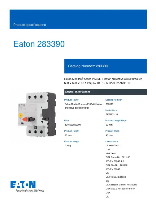
Eaton 283390Eaton Moeller® series PKZM01 Motor-protective circuit-breaker, 660 V 690 V: 12.5 kW, Ir= 10 - 16 A, IP20 PKZM01-16General specificationsEaton Moeller® series PKZM01 Motor-protective circuit-breaker283390PKZM01-16401508283390993 mm 90 mm 45 mm 0.3 kgUL 60947-4-1 CSA VDE 0660CSA Class No.: 3211-05 IEC/EN 60947-4-1 CSA File No.: 165628 IEC/EN 60947 ULUL File No.: E36332 CEUL Category Control No.: NLRV CSA-C22.2 No. 60947-4-1-14 CSA ULProduct NameCatalog Number Model Code EANProduct Length/Depth Product Height Product Width Product Weight CertificationsPush button Phase-failure sensitivity (according to IEC/EN 60947-4-1, VDE 0660 Part 102)Motor protection Phase failure sensitive Three-pole50,000 operations (at 400V, AC-3)50,000 Operations (Main conducting paths)Can be snapped on to IEC/EN 60715 top-hat rail with 7.5 or 15 mm height.25 Operations/h III3Motor protective circuit breaker Finger and back-of-hand proof, Protection against direct contact when actuated from front (EN 50274)6000 V AC 25 g, Mechanical, according to IEC/EN 60068-2-27, Half-sinusoidal shock 10 ms Branch circuit: Manual type E if used with terminal, or suitable for group installations, (UL/CSA) Also motors with efficiency class IE3-25 - 55 °C, Operating range-5 - 40 °C to IEC/EN 60947, VDE 0660≤ 0.25 %/K, residual error for T > 40°Max. 2000 m1 x (1 - 6) mm², ferrule to DIN 462282 x (1 - 6) mm², ferrule to DIN 46228Actuator type FeaturesFunctions Number of poles Lifespan, electricalLifespan, mechanicalMounting positionOperating frequency Overvoltage category Pollution degree Product categoryProtectionRated impulse withstand voltage (Uimp)Shock resistanceSuitable forTemperature compensation Altitude Ambient operating temperature - minTerminal capacity (flexible with ferrule)-25 °C55 °C25 °C40 °C40 °C80 °CDamp heat, cyclic, to IEC 60068-2-30 Damp heat, constant, to IEC 60068-2-782 x (1 - 6) mm²1 x (1 - 6) mm²18 - 1010 mm1.7 Nm, Screw terminals, Main cable50 Hz60 Hz16 A4 kW7.5 kW690 V690 V16 A60 kA DC, up to 250 V DC, Main conducting paths248 A, Irm, Setting range max.± 20% tolerance, Trip blocksBasic device fixed 15.5 x Iu, Trip Blocks 1 HP 3 HP 2 HPAmbient operating temperature - maxAmbient operating temperature (enclosed) - min Ambient operating temperature (enclosed) - max Ambient storage temperature - minAmbient storage temperature - maxClimatic proofing Terminal capacity (solid)Terminal capacity (solid/stranded AWG)Stripping length (main cable)Tightening torqueRated frequency - minRated frequency - maxRated operational current (Ie)Rated operational power at AC-3, 220/230 V, 50 Hz Rated operational power at AC-3, 380/400 V, 50 Hz Rated operational voltage (Ue) - minRated operational voltage (Ue) - maxRated uninterrupted current (Iu)Short-circuit current Short-circuit release Assigned motor power at 115/120 V, 60 Hz, 1-phase Assigned motor power at 200/208 V, 60 Hz, 3-phase Assigned motor power at 230/240 V, 60 Hz, 1-phase Assigned motor power at 230/240 V, 60 Hz, 3-phase5 HP10 HP10 HPScrew terminals10 A16 AOverload trigger: tripping class 10 A6.43 W0 W2.14 W16 A0 WMeets the product standard's requirements. Meets the product standard's requirements. Meets the product standard's requirements. Meets the product standard's requirements. Meets the product standard's requirements.Motor Starters in System xStart - brochureSave time and space thanks to the new link module PKZM0-XDM32MEProduct Range Catalog Switching and protecting motorsSwitching and protecting motors - catalogeaton-manual-motor-starters-characteristic-characteristic-curve-008.eps eaton-manual-motor-starters-pkz-characteristic-curve-002.epseaton-manual-motor-starters-characteristic-characteristic-curve-009.epsDA-DC-00004884.pdfDA-DC-00004914.pdfeaton-manual-motor-starters-circuit-breaker-pkzm01-dimensions.eps eaton-manual-motor-starters-mounting-3d-drawing-002.epseaton-general-ie-ready-dilm-contactor-standards.epseaton-manual-motor-starters-circuit-breaker-pkzm01-3d-drawing-002.epsETN.PKZM01-16Assigned motor power at 460/480 V, 60 Hz, 3-phaseAssigned motor power at 575/600 V, 60 Hz, 3-phaseConnectionOverload release current setting - minOverload release current setting - maxTripping characteristicEquipment heat dissipation, current-dependent PvidHeat dissipation capacity PdissHeat dissipation per pole, current-dependent PvidRated operational current for specified heat dissipation (In) Static heat dissipation, non-current-dependent Pvs10.2.2 Corrosion resistance10.2.3.1 Verification of thermal stability of enclosures10.2.3.2 Verification of resistance of insulating materials to normal heat10.2.3.3 Resist. of insul. mat. to abnormal heat/fire by internal elect. effects10.2.4 Resistance to ultra-violet (UV) radiation10.2.5 Lifting BrochuresCatalogsCharacteristic curve Declarations of conformity DrawingseCAD modelInstallation instructionsDoes not apply, since the entire switchgear needs to be evaluated.Does not apply, since the entire switchgear needs to be evaluated.Meets the product standard's requirements.Does not apply, since the entire switchgear needs to be evaluated.Meets the product standard's requirements.Does not apply, since the entire switchgear needs to be evaluated.Does not apply, since the entire switchgear needs to be evaluated.Is the panel builder's responsibility.Is the panel builder's responsibility.Is the panel builder's responsibility.Is the panel builder's responsibility.Is the panel builder's responsibility.The panel builder is responsible for the temperature rise calculation. Eaton will provide heat dissipation data for the devices.Is the panel builder's responsibility. The specifications for the switchgear must be observed.Is the panel builder's responsibility. The specifications for the switchgear must be observed.IL03402034ZIL03407011ZIL122012ZUWIN-WIN with push-in technology IL122023ZUDA-CD-pkzm01DA-CS-pkzm0110.2.6 Mechanical impact10.2.7 Inscriptions10.3 Degree of protection of assemblies10.4 Clearances and creepage distances10.5 Protection against electric shock10.6 Incorporation of switching devices and components 10.7 Internal electrical circuits and connections10.8 Connections for external conductors10.9.2 Power-frequency electric strength10.9.3 Impulse withstand voltage10.9.4 Testing of enclosures made of insulating material 10.10 Temperature rise10.11 Short-circuit rating10.12 Electromagnetic compatibility10.13 Mechanical function Installation videos Manuals and user guides mCAD modelEaton Corporation plc Eaton House30 Pembroke Road Dublin 4, Ireland © 2023 Eaton. All Rights Reserved. Eaton is a registered trademark.All other trademarks areproperty of their respectiveowners./socialmediaThe device meets the requirements, provided the information in the instruction leaflet (IL) is observed.。

断路器机械特性测试仪安全操作及保养规程1. 引言断路器机械特性测试仪是用于测试断路器的机械特性和性能的专业仪器。
为了保障测试人员的安全以及仪器的正常运行,制定本安全操作及保养规程。
本规程详细介绍了使用断路器机械特性测试仪的操作步骤、注意事项以及定期维护保养方法。
2. 安全操作规程2.1 设备检查在进行测试之前,必须进行设备检查,确保设备的正常工作。
具体步骤如下:•检查仪器的外观是否完好,无明显损坏或松动。
•检查电源线是否完好,并确保连接稳固。
•确保仪器接地良好,以防止静电危害。
2.2 操作环境测试时需要在合适的环境中进行,以确保测试结果的准确性和可靠性。
具体要求如下:•测试环境应干燥、通风良好,并远离易燃物品。
•测试区域应保持整洁,不得堆放无关物品。
•避免阳光直射和强光干扰。
2.3 操作步骤在进行测试前,请按以下步骤进行操作:1.打开仪器电源,确保仪器处于正常工作状态。
2.检查连接线缆是否正确连接,并确保连接稳固。
3.根据待测试的断路器类型,选择相应的测试模式。
4.将待测试的断路器正确接入测试仪上,并确保连接牢固。
5.运行测试程序,记录测试结果。
6.测试完成后,关闭仪器电源,并断开与待测试断路器的连接。
2.4 注意事项在操作断路器机械特性测试仪时,请注意以下事项:•请严格按照操作步骤进行操作,不得随意调整仪器设置。
•当仪器出现故障或异常情况时,应立即停止使用,并联系维修人员。
•在测试过程中,不得随意触碰无关物品,以免影响测试结果。
•长时间不使用仪器时,请将其断电并妥善存放。
3. 保养规程为了保障断路器机械特性测试仪的正常运行和使用寿命,制定以下保养规程:3.1 日常保养每次使用断路器机械特性测试仪后,请进行以下日常保养工作:•清洁仪器外观,使用清洁布轻轻擦拭。
•检查连接线缆是否有损坏或松动,并及时修复或更换。
•定期清理设备通风口和散热器,保持通风良好。
•定期检查电源线,确保无损坏。
3.2 定期保养除了日常保养外,还需要定期进行更彻底的保养工作,以确保设备的长期稳定运行:•根据制造商提供的保养手册,进行定期维护和保养工作。

FCPM-6000RCIntegrated Fr equency Co unter & Power MeterProduct OverviewMini-Circuits ’ FCPM-6000RC Integrated Frequency Counter & Power Meter is a compact (5.00 x 2.66 x 1.36”) precision test device controlled via USB or Ethernet (HTTP and Telnet protocols) or operated as standalone test instrument. It simplifies test setups by enabling synchronized frequency and power measurements from a single device. The unit features an LCD display allowing convenient readings directly off the measurement head, while our user-friendly GUI software enables easy remote test management via USB or Ethernet.Full software support is provided, including our user-friendly GUI application for Windows and a full API and programming instructions for both Windows and Linux environments (32-bit and 64-bit systems). The latest version of the full software package can be downloaded from https:///softwaredownload/fcpm.html at any time.USB / EthernetTrademarks: Windows is a registered trademark of Microsoft Corporation in the United States and other countries. Linux is a registered trademark of Linus Tor -valds. Mac is a registered trademark of Apple Corporation. Pentium is a registered trademark of Intel Corporation. Neither Mini-Circuits nor the Mini-Circuits FCPM-6000RC are affiliated with or endorsed by the owners of the above referenced trademarks Mini-Circuits and the Mini-Circuits logo are registered trademarks of Scientific Components Corporation.The Big Deal• Automatically synchronizedpower & frequency measurements • USB and Ethernet control• Includes GUI with measurement applications software, simplifying complex measurements • Measurement speed 30msCASE STYLE: JL202950Ω -30 dBm to +20 dBm, 1 MHz to 6000 MHzApplications• Production testing systems• Field testing & remote location monitoring • automatic, scheduled data collection• Evaluate high-power, multi-port devices with built-in virtual couplers/attenuators & other software tools.Included AccessoriesModel No.DescriptionB-RJ45-CBL-7+2.6 ft. USB cable1Software PackageRev. E ECO-019961EDR-11250Electrical Specifications (CW) 1, -30 dBm to +20 dBm, 1 to 6000 MHz2 Maximum continuous safe operational power limit: +23 dBm. Performance is guaranteed up to +20 dBm.3 The FCPM-6000RC can operate down to -32 dBm, however performance is guaranteed only in the range specified in the table.4 Minimum power for Frequency measurement at 190-240 MHz may degrade by up to 3 dB due to measurement band switching.5 When using Faster mode at high frequencies below -20dBm, use of averaging is recommended to prevent noise errors.6 When using Faster mode power reading below -20dBm, uncertainty value may increase by up to 0.2 dB relative to Low noise mode power reading.7 Accuracy shown using external 10 MHz reference synchronized to test signal. Using Internal Reference adds 2 ppm of tested frequency to the accuracy values shown.8 Software function set by user, default option 1000 mec.Permanent damage may occur if any of these limits are exceeded. Operating in the range between operating power limits and absolute maximum ratings for extended periods of time may result in reduced life and reliability.Reference Input(BNC-Female) Signal Input(N-Typ-Male) Power & Control (Push-Pull connector) ConnectionsTypical Performance Curves1.001.031.061.091.121.15100020003000400050006000V S W R (:1)Frequency (MHz)VSWR-4%-2%0%2%4%6%8%100020003000400050006000L i n e a r i t y (%)Frequency (MHz)Linearity @+25O C-0.4-0.3-0.2-0.10.00.10.20100020003000400050006000U U n c e r t a i n t y (d B )Frequency (MHz)Uncertainty of Power Measurement @ +25°C-42-39-36-33-30-270100020003000400050006000P o w e r I n (d B m )Frequency (MHz)Typ. Input Power Threshhold for FrequencyMeasurement @ +25°C-500-300-1001003005000100020003000400050006000U n c e r t a i n t y (H z )Frequency (MHz)Uncertainty of Frequency Measurement @ +25°COutline Drawing (JL2029)inchFCPM-6000RC to be used with the supplied control cable only.Connection diagramsConnection diagram for USB control Note:splitter not supplied by Mini-Circuits Connection diagram for Ethernet control, using PoE systemConnection diagram for Ethernet control, using power adapterGraphical User Interface (GUI) for Windows Key Features:• Automatically synchronized power and frequency measurements.• Relative and Average power measurements• Setting measurement speed for power and frequency independantly.• Freq. & Power measurment data recording • Measurement application tools• online graphical display of power measurement • USB, HTTP or Telnet control of FCPM• Setting Ethernet configurationSoftware & Documentation Download:• Mini-Circuits’ full software and support package including user guide, Windows GUI, DLL files, programming manual and examples can be downloaded free of charge from https:///softwaredownload/fcpm.html .• Please contact ****************************** for supportApplication Programming Interface (API)Windows Support:• API DLL files exposing the full power sensor functionality • ActiveX COM DLL file for creation of 32-bit programs • .Net library DLL file for creation of 32 / 64-bit programs• HTTP Get/Post and Telnet protocols use SCPI commands to provide full control.• Supported by most common programming environments (refer to application note AN-49-001 for summary of tested environments)Linux Support:• Full power sensor control in a Linux environment is achieved by way of USB interrupt commands.ModelDescriptionFCPM-6000RCIntegrated Frequency Counter & Power MeterOrdering Information Additional NotesA. Performance and quality attributes and conditions not expressly stated in this specification document are intended to be excluded and do not form a part of this specification document.B. Electrical specifications and performance data contained in this specification document are based on Mini-Circuit’s applicable established test performance criteria and measurement instructions.C. The parts covered by this specification document are subject to Mini-Circuits standard limited warranty and terms and conditions (collectively, “Standard Terms”); Purchasers of this part are entitled to the rights and benefits contained therein. For a full statement of the Standard Terms and the exclusive rights and remedies thereunder, please visit Mini-Circuits’ website at /MCLStore/terms.jspCalibrationDescriptionCAL-FCPM-6000RCCalibration ServiceClick HereIncluded Accessories Part No.DescriptionUSB-RJ45-CBL-7+6.6 ft (2 m) “Y” data cable with USB Type-A and RJ45 plug connectors 910 Power plugs for other countries are also available, if you need a power plug for a country not listed in the table please contact testsolutions@ for su pport.11 The USB-AC/DC-5 may be used to provide the 5VDC power input via USB port if operating with Ethernet control. Not required if using USB control.Optional AccessoriesDescriptionUSB-AC/DC-5AC/DC 5V DC Power Adapter with US, EU, IL, UK, AUS, and China power plugs 10,11USB-RJ45-CBL-7+ (spare) 6.6 ft (2 m) “Y” data cable with USB Type-A and RJ45 plug connectors NF-SM50+ N-Type Female to SMA Male Adapter (For mating with SMA devices).NF-SF50+N-Type Female to SMA Female Adapter NF-BM50+N-Type Female to BNC Male Adapter.9 FCPM-6000RC to be used with the supplied control cable only.。
高精度:采用功能强大的微处理器芯片,尤其采用交流采样技术,电压测量精度为±1%,能分别显示
,保证全球通用(不能使用于变频器输出回路)。
,使失压保护装置的规格大为减少,便高可靠:采用独特的三相电源供电技术,即使在极低电压、甚至在缺相情况下,也能保证保护、报警、
相序保护器原理图
相序监测:当失压保护装置通电时,如果相序正确并且所有三相带电,继电器吸合。
过欠压保护器原理
缺相保护器原理图
缺相检测:当缺相故障时,继电器断电。
正常工作(无故障)时继电器吸合。
当缺相时立即断电。
电压不平衡保护器原理图
A、B、C:“不平衡”字符闪烁D:“不平衡”字符长亮。
断路器测试仪也叫高压开关测试仪,全称是高压开关动特性测试仪。
随着社会的发展,人们对用电的安全可靠性要求越来越高,高压断路器在电力系统中担负着控制和保护的双重任务,其性能的优劣直接关系到电力系统的安全运行。
机械特性参数是判断断路器性能的重要参数之一。
高压关机性测试仪是针对各种高压开关研制的一种通用型电脑智能化测试仪器。
该仪器应用光电脉冲技术,单片计算机技术及可靠的抗电磁辐射技术,配以精确可靠的速度/距离传感器,可用于各种电压等级的真空、六氟化硫、少油、多油等高压开关的机械性参数的调试与测量。
该仪器接线方便、操作简单、操作时只需一次合(分)动作便可得到合(分)闸全部数据。
并能打印所需的全部数据,断口电流波形和动触头运动曲线,便于分析保存。
艾驰商城是国内最专业的MRO工业品网购平台,正品现货、优势价格、迅捷配送,是一站式采购的工业品商城!具有10年工业用品电子商务领域研究,以强大的信息通道建设的优势,以及依托线下贸易交易市场在工业用品行业上游供应链的整合能力,为广大的用户提供了传感器、图尔克传感器、变频器、断路器、继电器、PLC、工控机、仪器仪表、气缸、五金工具、伺服电机、劳保用品等一系列自动化的工控产品。
如需进一步了解ABB断路器、施耐德断路器的选型,报价,采购,参数,图片,批发等信息,请关注艾驰商城。
/。
剩余电流断路器测试仪的性能参数介绍断路器操作规程B型剩余电流断路器测试仪(以下简称测试仪)是专为剩余电流断路器的性能测试而研制;它是检测B型剩余电流断路器脱扣电流和分断时间的关键仪器。
测试仪的功B型剩余电流断路器测试仪(以下简称测试仪)是专为剩余电流断路器的性能测试而研制;它是检测B型剩余电流断路器脱扣电流和分断时间的关键仪器。
测试仪的功能能够充分GB16916.1—2023、GB16917.1—2023和GB22974—2023标准对剩余电流断路器的测试要求。
测试仪适用于电子式和电磁式的剩余电流断路器。
1P+N、2P、3P、3P+N、4P的断路器均能测试,输出剩余电流为2A。
测试仪的功能操作接受触摸屏,断路器动作后,脱扣电流和分断时间均能保持,便于读数和记录。
系统显示和操作接受流行的工业级触摸屏,操作简单;剩余电流断路器测试仪的性能参数环境温度:0℃——40℃环境相对湿度:不大于80%RH电源电压要求:交流220V,50Hz(仪器工作电源)辅佑襄助电源要求:三相四线输入380V,大于2A接地方式:牢靠接地测试仪输出的电流值为真有效值,测试不确定度小于1%;(1)变频模式交流剩余电流范围:0~2A;(2)50Hz交流剩余电流范围:0~2A;(3)脉动直流剩余电流注意事项:对剩余电流断路器进行特性测试之前,请接线图依照下面说明正常接线;检查剩余电流断路器是否有相线与相线之间的短路以及相线与零线之间的短路现象。
用该测试仪对有相间短路现象的漏电断路器进行测试时,会对仪器造成严重的损坏。
用该测试仪接线时,确定需要注意上下桩头接线需要一一对应,不能交叉连接,否则会引起故障或仪器损坏;—专业分析仪器服务平台,试验室仪器设备交易网,仪器行业专业网络宣扬媒体。
相关热词:等离子清洗机,反应釜,旋转蒸发仪,高精度温湿度计,露点仪,高效液相色谱仪价格,霉菌试验箱,跌落试验台,离子色谱仪价格,噪声计,高压灭菌器,集菌仪,接地电阻测试仪型号,柱温箱,旋涡混合仪,电热套,场强仪万能材料试验机价格,洗瓶机,匀浆机,耐候试验箱,熔融指数仪,透射电子显微镜。
瑞典保加玛(programma)TM1600/ MA61断路器机械特性测试仪
产品特点:
▲采用模块化结构,TM1600时间测量通道可为4-16个通道
▲MA61测速通道可为2-6个的组合,来满足不同应用的需要
▲系统结构精巧,只有10Kg左右,工作电源为交直流两用且自动切换,并且内部带有可自动充电电池▲TM1600每个计时通道都是独立的,可测主触点和带合闸电阻触点的动作时间
▲内置打印机,可现场打印测试结果
▲配置各种传感器(可选件)及安装套件以适应各生产厂家不同结构型式的操作机构的应用要求
▲既可面板操作也可通过PC CABA 软件控制,方便灵活(PC CABA 软件为选购件)
▲中文操作界面,方便使用
▲建立强大的数据库,对断路器实行电子文档管理(PC CABA 软件为选购件)
▲DRM1000大电流发生器应用于测试Siemens石墨触头断路器的合/分时间
▲动态电阻测试方法可分析拉弧触点磨损及断路器两端同时接地时进行测试
产品主要功能:
▲断路器主触点/带合闸电阻合、分时间,弹跳,同期
▲断路器总行程,超程,反弹,合、分平均速度,刚合/刚分速度
控制模式:
▲单合,单分,合分,分合,分合分
应用领域:
应用于测试各种高压变电站现场和工业环境中的断路器(开关)测试,
主要有:
ABB:HPL550P LTB145 LTP245 VD4
SIEMENS:3AP 3AQEE 3AQEG 3AT
AREVA:GL312 GL314 GL317
及同类型国产断路器
CABAWIN完善便捷的管理软件
▲备注:有关CABA Win软件功能及应用图示请点击:产品相关文档下载: 右键-->"另存为"下载
软件操作界面
完善的管理
直观的结果
产品技术指标:
一、TM1600技术规格及参数
▲计时通道:4-16(若不配MA61,最多可选24个计时通道)
▲时间测量
▲范围:0至6.5s(选购件CABA Win软件:0-200s)
▲分辨率:0.1ms
▲精度:0.01%读数±0.1ms
▲时间测量启动方式,可选择下列三种方式:
▲启动极时器工作开始时间测量1
▲当从TM1600操作断路器时2
▲当外触发信号输入时3
触发信号输入:为一独立输入通道且带有自己的电压源,当检测到电压或者接点闭合时开始计时测量
触发信号输出:可达1A的闭合容量
二、计时模块
▲通道数:每个模块含4个计时通道
▲计时通道:每个计时通道都是独立的,各自带有直流电压源,每个计时通道都可测量主触点,带电阻接电点及电压感应接点(湿接点),输入回路具有2.5KV的光隔离信号隔离器
▲主接点的时间测量:0~250Ω测试电压约为25V,测量电流限制在150mA左右
▲电阻接电点的时间测量:0~250Ω~3KΩ,测试电压约为50V,测量电流限制在30mA左右(0~250Ω以下,3KΩ以上改变接线方式也可测试)
▲电压检测(湿接点):12~250V检测指示有否电压存在(无极性)负载容量小于3W
▲输入端子的防暂态尖波保护:所有输入端子都有保护二极管
▲输入端扦孔对扦孔间:18KW,8-20us
▲输入端扦孔对地间:4.8KW,8-20us
▲感应保护:对地电容性放电,每个输入端子最大为15mA
三、断路器操作控制
▲接点:二组独立的无电位接点以启动分闸和合闸二组线圈
▲接点性质:无弹跳接点,闭合时间小于0.1ms
▲操作顺序设定:单合(C),单分(O),合-分(C-O),分-合(O-C),分-合-分(O-C-O)
▲接点开断容量:25A,250V交流或直流
▲断路器操作启动方式:通过面板上的启动按钮或通过光隔离器的外触发输入接点的闭合操作来遥控启动
▲控制脉冲与计时启动的时间差:小于0.1ms
四、MA61
▲通道数:0- 6个
▲测速通道:可为2-6个的组合
▲测速通道可选:
▲MA61-2 (2个的组合)
▲MA61-4 (4个的组合)
▲MA61-6 (6个的组合)
▲测量范围:传感器电阻:0.1-10KΩ,电压:-4至+4V
▲测量分辨率:0.03%
▲基本精度:0.1%
▲动态误差:位移1%,速度3%
▲时基精度:0.02%
▲测量时间长度:50,100,200,400,1000ms,用户可选(CABA Win 可达200s)
▲采样频率:1-20KHz ( 40KHz 任选)
▲显示:带有背景光的LCD显示
五、打印输出:
▲内装有高速热敏打印机,也可外接打印机
▲输出格式:有多种图形/表格方式供选择(选购件CABA Win软件)
其他
电源:95-265V交流或100-375V直流(自动切换)
内装充电电池:内装带有自动充电器的电池,充好电后,可正常使用1小时以上
介电强度:符合IEC348和IEC255-5
环境温度:
TM1600:工作温度:-20℃-+50℃存放温度:-30℃-+70℃
MA61:工作温度:-10℃-+50℃存放温度:-30℃-+85℃
外形尺寸:400×250×153mm
整机重量:约10Kg
产品配置:
TM1600+ MA61-2(测速通道:2个的组合)含10米测试线
TM1600+ MA61-4(测速通道:4个的组合)含10米测试线
TM1600+ MA61-6(测速通道:6个的组合)含10米测试线
选购件:
CABA Win软件
直线位移传感器TS150
旋转角度传感器IP601
备注:以上所列产品技术指标及参数仅供参考,实际指标及参数以厂商随机所附:产品技术标准及校验证书为准。
备注:资料均来自保加玛官方或相关网站“programma”商标版权归其所有。