SU18-40a倍加福光纤放大器说明书
- 格式:pdf
- 大小:602.49 KB
- 文档页数:5

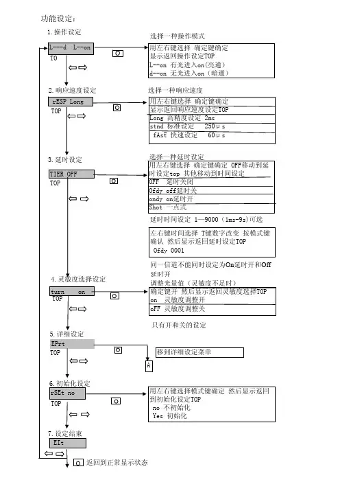
功能设定:
调整
二点式设定
返回到通常状
态
反射型
1.对准检测物校正
2.不对准任何背景物校正
转换至RUN
返回到通常状态
区域设定
在背景前不放置任何物体校正然后在背景前放置检测物校正
透明体检测设定
转换至SET
SET RUN
返回到正常状态
转换至RUN
对射型对准检测物设定
菜单校正自学习错误显示
菜单调整在RUN模式下按UP/DOWN就可以调整,用UP/DOWN选择键调整到所需要的任何值。
1.通常状态时300 350设定完成后5秒
自动返回到通常状态(不必再重新操作)
2.区域校正时
设定下限值(远)
设定完成后5秒
自动返回到通常
状态(不必再重
新操作)
设定完成后5秒自动返回到通常状态(不必再重新操作)在调整过程中有时会出现调整错误信息的显示。
放大器参数说明工作频率范围(F):指放大器满足各级指标的工作频率范围。
放大器实际的工作频率范围可能会大于定义的工作频率范围。
功率增益(G):指放大器输出功率和输入功率的比值,单位常用“dB”。
增益平坦度(ΔG):指在一定温度下,在整个工作频率范围内,放大器增益变化的范围。
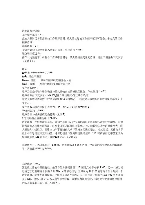
增益平坦度由下式表示(见图1):图1ΔG=±(Gmax-Gmin)/2dBΔG:增益平坦度Gmax:增益——频率扫频曲线的幅度最大值Gmin:增益——频率扫频曲线的幅度最小值噪声系数(NF):噪声系数是指输入端信噪比与放大器输出端信噪比的比值,单位常用“dB”。
噪声系数由下式表示:NF=10lg(输入端信噪比/输出端信噪比)在放大器的噪声系数比较低(例如NF<1)的情况下,通常放大器的噪声系数用噪声温度(T)来表示。
噪声系数与噪声温度的关系为:T=(NF-1)T0 或NF=T/T0+1T0-绝对温度(290K)噪声系数与噪声温度的换算表(见图2)1分贝压缩点输出功率(P1dB):放大器有一个线性动态范围,在这个范围内,放大器的输出功率随输入功率线性增加。
这种放大器称之为线性放大器,这两个功率之比就是功率增益G。
随着输入功率的继续增大,放大器进入非线性区,其输出功率不再随输入功率的增加而线性增加,也就是说,其输出功率低于小信号增益所预计的值。
通常把增益下降到比线性增益低1dB时的输出功率值定义为输出功率的1dB压缩点,用P1dB表示。
(见图3)典型情况下,当功率超过P1dB时,增益将迅速下降并达到一个最大的或完全饱和的输出功率,其值比P1dB大3-4dB。
三阶截点(IP3):测量放大器的非线性特性,最简单的方法是测量1dB压缩点功率电平P1dB。
另一个颇为流行的方法是利用两个相距5到10MHz的邻近信号,当频率为f1和f2的这两个信号加到一个放大器时,该放大器的输出不仅包含了这两个信号,而且也包含了频率为mf1+nf2的互调分量(IM),这里,称m+n为互调分量的阶数。
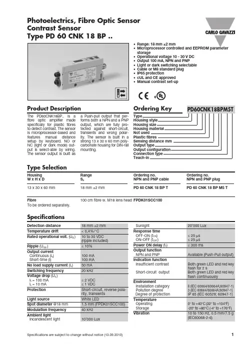
Specifications are subject to change without notice (13.09.2010)1Product DescriptionThe PD60CNK18BP.. is a fibre optic amplifier made specifically for plastic fibres to detect contrast. The sensor is microprocessor-based and features manual distance setup by keyboard. NO or NC (light or dark mode) out-put is select-able by wiring. The sensor output is built asa Push-pull output that per-forms both a NPN and a PNP output, which are fully pro-tected against short-circuit, transients and wrong polar-ity. The sensor is built in a strong 13 x 30 x 60 mm poly-carbonate housing for DIN-rail mounting.• Range: 18 mm ±2 mm• Microprocessor controlled and EEPROM parameter storage• Operational voltage 10 - 30 V DC • Output 100 mA, NPN and PNP • Light or dark switching selectable • Cable or M8 standard plug • IP65 protection• cUL and CE approved • Manual contrast set-upPhotoelectrics, Fibre Optic Sensor Contrast SensorType PD 60 CNK 18 BP ..Type SelectionHousing Range Ordering no. Ordering no. W x H x D S n NPN and PNP cable NPN and PNP plug 13 x 30 x 60 mm 18 mm ±2 mm PD 60 CNK 18 BP T PD 60 CNK 18 BP M5 T Fibre100 cm fibre w. M18 lens head FPDK01SCC100To be ordered separately.Specifications2Specifications are subject to change without notice (13.09.2010)Wiring DiagramKeyboard and LEDDimensionsPD60CNK18 BP..Specifications (cont.)Teach-inColour 1Colour 2 sec.Output can be inverted by teaching colour 2 firstSpecifications are subject to change without notice (13.09.2010)3Delivery Contents• Photoelectric switch: PD60CNK18BP..• Installation instruction• Packaging: Cardboard boxAccessories• Plastic fibre type FPDK01SCC100PD60CNK18 BP..Relief of cable strainProtection of the sensing faceSwitch mounted on mobile carrierTo avoid interference from inductive voltage/ current peaks, separate the prox. switch power cables from any other power cables, e.g. motor, contactor or solenoid cablesIncorrectCorrectThe cable should not be pulledA proximity switch should not serve as mechanical stopAny repetitive flexing of the cable should be avoided。

U S E R’S M A N U ALN X L-N2N X L-N1N X L-N4M O D E L S:• IRS (International Rectifier)Full Range Capable Class-D Amp Class• Ultra Compact Size for easy installation forPower Sports Applications• Variable Full Crossover Filter: LPF / FULL / HPF(NXL-4 & NXL-2)• Surface Mount Component Technology• Audio Precision Quality Control Verification• Stable & Reliable Four Layer PCB Trace Layout• Fully Aluminum Chassis Design• Power & Protection LED Light Status Indicator• Short Circuit, thermal and voltage protection• IPX67 Rating Waterproof for Power Soprts Applications NXL-N2NXL-N1NXL-N4Thank you for choosing DS18 NXL-N amps!To Take full advantage of the DS18 NXL-N amps you have just purchased, please read and follow the instructions in this manual. As with all of our products, professional installation by an authorized DS18 NXL-N amps dealer is highly recommended!Fully variable crossovers promote installation ease and save the cost of outboard crossovers. Additionally, they may be used in conjunction with outboard passive or active crossovers, depending on the complexity required by the system. The 12 dB per octave slope offers steep roll-off above or below the selected frequency.Against Overload, Short Circuit, Thermal, and Reverse Polarity. These protection features are designed to protect the amplifier from misuse, as well as from common causes of amplifier failure. The DS18 NXL-N waterproof amplifiers offer high quality audio reproduction for the audiophile and the everyday listener alike. All models feature fully variable crossovers with 12 dB per octave slopes, allowing you the ability to tailor the sound to best fit the speakers and your listening preferences.Ensures solid electrical connections that resist corrosion.Platinum Finish Connections Fully Variable Crossovers Protection CircuitryProfessional installation by an authorized DS18 NXL-N amps dealer is highly recommended! Otherwise, the performance of your new gear may not be satisfactory. In the event that you decide to do your own installation, please read and follow this manual very carefully. Failure to do so may compromise the integrity of this product, your vehicle, and possibly void the product warranty.Amplifiers are generally mounted in closed compartments of the vehicle or watercrafts. Select a location that will provide adequate ventilation for the amplifier. Avoid mounting the amplifier in exposed areas. Secure the amplifier with the screws provided.Before securing the amplifier, inspect the mounting location carefully to ensure that you do not drill into or damage any electrical, hydraulic, fluid or fuel lines.INPUT SECTIONBecause of the wide range of head unit output configurations all DS18 NXL-N amps have an adjustable input sensitivity of “Gain”. The gain is not a volume or a power limiting control like a throttle. It makes the amp more sensitive to input from the stereo; with the gain up, the amp will reach full output at a lower volume setting on the deck. At higher gain settings the amp also becomes more and more sensitive to noise from the vehicles’s electrical system. Try to run the gain at the lowest setting possible for your system.There is no correct gainsetting, becausespeakers requiredifferent powerdemands to reach thesame output, the gainsmost often need to beused to compensate forthese differences. If youtried to set all the gainsat half way you wouldprobably find thesystem didn’t sound very good. Using good judgment and listening carefully to each speaker is still the best way to tune a system.A crossover is a devicethat removes unwantedfrequencies from aspeaker or amplifier. Atweeter can easily bedestroyed by bass notesif they are not filteredout. Likewise asubwoofer will notsound natural if it isplaying midrangenotes. A crossoverremoves these sounds from the speaker. As you might guess, careful adjustmentin need to ensure that all the speakers are playing the right sounds and that you are left with no “holes” or low spots in the frequency response.DS18 NXL-N amplifiershave an adjustable bassboost. Begin youradjustments at lowvolume. If you do not hearany improvement thenwoofer does not need anybass boost.The Low Pass Filter (LPF)must be switched on forthe bass boost to activate.Use Bass Boost carefully. The demands on power output are tremendous. Try to minimize the use by changing woofer position or the enclosure size.This amplifier is a multichannel amplifierdesign, meaning it hasmore than one channelof speaker outputs. It isequipped with a largeblock style terminal forspeaker connection.Make this connectioncarefully and neatly.Strip your wire back andtwist the exposed leadsand insert them into the block terminal while being careful that there is no loose or frayed strands of wire and tighten the Allen head screw down on the terminal till the wire is tightly secured in place. If the wires ever come in contact with each other the amplifier will go into protection.1. Before you start, disconnect the negative cable from the car battery.Tape up the end so it is isolated from the battery.2. Run an appropriate gauge wire from the battery to the amplifier. Plan this partof the installation carefully. This cable will carry very high current, if it should short to the body and it is not properly fused it could catch fire.3. Connect the power wire to the battery using a fuse capable of the total currentload of all amplifiers connected. Don’t install the fuse yet. Wait until the end.Locate the fuse as close as possible to the battery. If the fuse is further than 18 inches (wire length) from the battery you should reevaluate the wire and fuse placement.4. Find the closest clear metal area to the amp for a ground. Sand, grind orscrape all paint and undercoating from the body and screw the groundsecurely in place.It is advisable to test the ground with an ohmmeter between the ground cable and the negative battery cable to ensure a good low resistance connection. Some allowys used in modern cars do not offer the best ground. If you believe this is the case - first consult with the vehicle manufacturer.5. Run the speaker wire to the speakers. It is advised that you leave some extrawire at this point. You can fix it later.6. If you haven’t done so already, mount the amp now.7. Connect the power and ground to the amplifier.ONLY AFTER THIS STEP - SHOULD YOU INSTALL THE FUSE AT THE BATTERY.8. Connect the remote wire from the head unit to the amplifier.Now is a good time to turn on the amp for the first time. Make sure it turns on properly and does not go into protection mode.9. Connect the speaker wires to the amp and speakers (make sure the amp isoff first). Make sure the polarity (+) and (-) is correct.10. Connect the RCA’s to the amp.11. Double check the amplifier controls at this time. Make sure everything is setcorrectly for your system.12. Now you’re ready to play it for the first time. It is best to leave the gain all theway down at first. Start with the head unit volume low and work your way up.13. Now you can tune the amp. Take your time and make only one adjustment ata time. It may take some time to get the system fully adjusted. During this timethe amp is drawing current from the battery. You should check the batteryvoltage from time to time and recharge it, if it gets low. That’s it. You’re done.Now have fun.1.56” (39.8 mm)N X L -N 2N X L -N 1N X L -N 4Should your amplifier require service please consult with the dealer from which it was purchased, orcontact DS18 Audio local Dealer.Do not attempt to return your amplifier directly to us without first calling for a Return Authorization Number.Units received without an accompanying ReturnAuthorization Number will be processed more slowly.Additionally, you must include a copy of yourpurchase receipt from an authorized dealer forconsideration of in-warranty service; otherwise repair charges will apply. Units received without a receipt will be held for 30 days, allowing us time to contact you and obtain a copy of the receipt. After 30 days, allunits will be returned without repair.O MD S18.C。
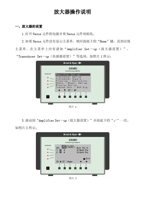
放大器操作说明一、放大器的设置1.打开Nexus 元件的电源并使Nexus 元件初始化。
2.如果Nexus 元件没有显示主菜单,则应按底下的“Home ”键,直到出现主菜单。
在主菜单上应有诸如“Amplifier Set -up (放大器设置)”,“Transducer Set -up (传感器设置)”等选项。
如照片1所示:3.滚动到“Amplifier Set -up (放大器设置)”并按底下的“↙”一次。
如照片2所示:照片 1照片 24.在“Amplifier Set -up (放大器设置)”菜单下,应通过在底下箭头键来滚动到“Hz ”,以确保“Hz ”显示加亮。
一旦“Hz ”显示加亮,则按 “Ch ↓”键。
随后应用“+”和“-”按键来设置Hz (频率)为A 。
一旦通道1设置为A ,则应按 “Ch ↓”键,并对通道2,3和4作同样的工作。
如果是2通道Nexus 元件,那么只需要编程两个通道。
当所有通道设置为A 时,按“Home ”键返回。
如照片3所示:然后,用“→”键移动到“Out (输出)”。
一旦“Out (输出)”被显示加亮,使用“Ch ↓”键和“+”与“-”键把每个通道都设置为316mV/Pa 。
当所有通道都设置为316mV/Pa 后,按“Home ”键返回。
最后回顾一下菜单,确保所有的通道都被分别设置在A 下,“Out ”输出为316 mV/Pa 。
当所有设置项都设置正确后,按“Home ”键返回。
如照片4所示:照片 3滚动到“Transducer Set -up (传感器设置)”下并按底下的“↙”一次。
如照片5所示:(此步可以省略,因为麦克风的灵敏度是自动识别的不用设置)编辑此菜单需要声学传感器的校准数值。
当得到校准数值后,滚动到“Sensitivity (灵敏度)”并按“Ch ↓”键。
如照片6所示:照片 4照片 5随后将处在显示加亮的十进制数值的通道#1。
用“+”与“-”键把此数值设置为对应于此通道/声学传感器的校准/灵敏度数值。

TED SERIESINSTRUCTION MANUALCONTROLS1 and2 OUTPUT LEDsThe yellow LEDs indicate the status of the corresponding outputs duringthe normal operating status.1 and2 READY/ERROR LEDs (bicolour)The bicoloured LEDs are permantely green indicate that the receivedsignal guarantees a stable output status.The alternative blinking of the LEDs indicate a wrong setting condition.Please refer to the “SETTING” paragraph for correct for setup procedureindications.SET1 and SET2 PUSHBUTTONA long pressure on the pushbutton activates the self-setting procedureof the corresponding channels.INSTALLATIONprotection lid can be removedopening it completely and pullingit slightly.Mount the sensor on a DIN rail orthanks to the fixing holes usingscrews (M3x20 or longer) withwashers.Installation of the fibre-optics:Press the lock pushbutton and keep it pressed until all the fibres hasbeen completely inserted.Insert the fibres in the corresponding holes as described in thedimension drawing.The transparent CLEAR-LOCK TM fixing block allows to easily check thatthe fibres are close to the photoelements.The insertion resistance is due to the O-ring seal; please insert the fibresfor about 6mm deeper until they touch the photoelements.CONNECTIONSOUTPUT 1OUTPUT 20 VM8 CONNECTOR12 … 24 VdcOUTPUT 10 VOUTPUT 2(WHITE)(BROWN)(BLUE)(BLACK)+-TECHNICAL DATAPower supply: 12 … 24 Vdc±10% (reverse polarity protection)Ripple: 2 Vpp max.Current consumption(output current excluded): 60 mAOutputs: NPN (TED-x-N) or PNP (TED-x-P)Output current: 100 mA max. at 25 °C derating –2 mA/°COutput saturation voltage: 1.2 V max.Response time: 250 μs max.Indicators: 2 OUTPUT LEDs (YELLOW) and 2 READY/ERROR LEDs (RED/GREEN)Setting: 2 SET1 and SET2 pushbuttonsData retention: non volatile EEPROM memoryOperating temperature: -10 … 55 °CStorage temperature: -25 … 70 °CElectrical shock protection: Class 2Operating distance (typical values): proximity (with OF-xx-ST fibre-optic) 0 … 70 mmthrough beam (with OF-xx-ST fibre-optic) 0 … 280 mmEmission type: red (630 nm)Ambient light rejection: according to EN 60947-5-2Vibrations: 0.5 mm amplitude, 10 … 55 Hz frequency, for every axis (EN60068-2-6)DARK/LIGHT selection: 11 ms (30 G) 6 shock for every axis (EN60068-2-27)Housing: PolycarbonateMechanical protection: IP65Connections: 2 m cable ∅ 4.5 mm / M8-4 pole connectorWeight: 115 g. max. cable vers. / 30 g. max. connector vers.SETTINGEASY TOUCH™The sensor uses the patent-covered EASY TOUCH™ technology thatallows a rapid and safe self-setting of the product.Two different setting possibilities are available:- EASY TOUCH™; a long pressure of the SET pushbutton allows self-setting.- FINE DETECTION; to be used only in particularly critical conditions.This setting procedure is used only when the EASY TOUCH™ is notsufficient.TED settingThe EASY TOUCH™ foresees the LIGHT operating mode.Thus using proximity fibres, the output is closed and the output LED isON when the object is detected.Using through beam fibres, the output is closed and the output LED isON when the object does not interrupt the beam (i.e. the object is notdetected).- EASY TOUCH™ (standard detection)Place the object to detect either in front of the proximity fibres withinthe operating range, or in the middle of the through beam fibres.Press the SET1 pushbutton (or SET2 for the second channel).Keep the pushbutton pressed until the signalling LED turns green andthe READY/ERROR LED turns off.Release the SET pushbutton. The sensor is now ready to detect theobject.- Fine detectionThis mode offers an improved detection precision. The sensor canfunction either in the DARK operating or in the LIGHT operatingmode.1) Place the object to detect in front of the proximity fibres within theoperating distance, or in the middle of the through beam fibres.Press the SET1 pushbutton (or SET2 for the second channel) andkeep it pressed until the READY/ERROR LED turns on.Keep it pressed until the LED turns off and maintain the pressureuntil the signalling LED begins to blink green.The sensor is now ready for the second setting.2) Remove the object to detect and press the SET pushbutton againuntil the READY/ERROR LED turns on.The sensor is now ready to detect very precisely the pre-set object.If the READY/ERROR LED begins to blink red and green, thesetting has failed, as the contrast is insufficient. Thus the settingprocedure has to be repeated.Following this setting procedure, the sensor functions in the LIGHTmode with proximity fibres and in the DARK mode with through beamfibres. To set the sensor in the DARK mode for proximity or LIGHTmode for through beam, invert the sequence given above.The operative DARK/LIGHT mode is automatically selected by thesensor when is used as contrast sensor.‘OR’ function by means of parallel output connectionThe 1 and 2 outputs can be connected together in parallel, obtainingan ‘OR’ function; this means that the common output is activatedeven if just one of the two fibres has detected the object.DECLARATION OF CONFORMITYWe DATALOGIC AUTOMATION declare under our sole responsibilitythat these products are conform to the 2004/108/CE and successiveamendments.WARRANTYDATALOGIC AUTOMATION warrants its products to be free fromdefects.DATALOGIC AUTOMATION will repair or replace, free of charge, anyproduct found to be defective during the warranty period of 36 monthsfrom the manufacturing date.This warranty does not cover damage or liability deriving from theimproper application of DATALOGIC AUTOMATION products.DATALOGIC AUTOMATIONVia Lavino 265 - 40050 Monte S.Pietro - Bologna – ItalyTel: +39 051 6765611 - Fax: +39 051 6759324e-mail:********************************Datalogic and the Datalogic logo are registered trademarks of DatalogicS.p.A. in many countries, including the U.S.A. and the E.U.826000992Rev.C© Copyright Datalogic 2008-2010。


光纤放⼤器的常规调节⽅法光纤放⼤器的常规调节⽅法使⽤漫反射光纤,状态在L.ON1.将MODE 拨到L.ON2.通电后,将光纤对到检测物体,红光OUT亮,将旋钮左旋到OUT灯灭,再将旋钮向右以1/4圈的速度旋转到OUT红灯亮,调整完毕。
如需反向动作,做L.ON/D.ON切换使⽤对射光纤,状态在L.ON1.将MODE拨到L.ON2.通电后,将光纤安装好,没有检测物体的情况下,如红灯亮,将旋钮左转到OUT灯灭,再将旋钮向右以1/4圈的速度旋转到OUT红灯亮,调整完毕。
将检测物体放⼊光纤之间,OUT灯灭。
如需反向动作,做L.ON/D.ON切换光纤放⼤器⼯作原理及其在⽆线光通信的应⽤0 引⾔⽆线光通信是以激光作为信息载体,是⼀种不需要任何有线信道作为传输媒介的通信⽅式。
与微波通信相⽐,⽆线光通信所使⽤的激光频率⾼,⽅向性强(保密性好),可⽤的频谱宽,⽆需申请频率使⽤许可;与光纤通信相⽐,⽆线光通信造价低,施⼯简便、迅速。
它结合了光纤通信和微波通信的优势,已成为⼀种新兴的宽带⽆线接⼈⽅式,受到了⼈们的⼴泛关注。
但是,恶劣的天⽓情况,会对⽆线光通信系统的传播信号产⽣衰耗作⽤。
空⽓中的散射粒⼦,会使光线在空问、时间和⾓度上产⽣不同程度的偏差。
⼤⽓中的粒⼦还可能吸收激光的能量,使信号的功率衰减,在⽆线光通信系统中光纤通信系统低损耗的传播路径已不复存在。
⼤⽓环境多变的客观性⽆法改变,要获得更好更快的传输效果,对在⼤⽓信道传输的光信号就提出了更⾼的要求,⼀般地,采⽤⼤功率的光信号可以得到更好的传输效果。
随着光纤放⼤器(EDFA)的迅速发展,稳定可靠的⼤功率光源将在各种应⽤中满⾜⽆线光通信的要求。
1 EDFA的原理及结构掺铒光纤放⼤器(EDFA)具有增益⾼、噪声低、频带宽、输出功率⾼、连接损耗低和偏振不敏感等优点,直接对光信号进⾏放⼤,⽆需转换成电信号,能够保证光信号在最⼩失真情况下得到稳定的功率放⼤。
1.1 EDFA的原理EDFA的泵浦过程需要使⽤三能级系统,如图1所⽰。
宽带放大器设计说明书目录摘要 (1)第一章引言 (1)1.1宽带放大器的概述 (1)1.2本课题设计的意义 (3)第二章总体设计 (3)2.1宽带放大器的主要技术指标 (3)2.2设计要求 (4)2.3 方案论证与比较 (4)2.3.1 可控增益放大器 (4)2.3.2 后级固定增益放大器 (5)2.4 总体设计思路 (5)2.5 AD603芯片简介 (6)2.5.1 AD603的特性 (6)2.5.2 电气性能 (6)2.5.3 使用注意事项 (8)2.6 直流稳压电源 (9)2.7 前级放大器和AGC的设计 (9)2.8后级放大设计 (12)第三章电路安装与调试 (14)3.1 电路的安装 (14)3.2主要测试仪器 (14)3.3 测试 (14)总结 (15)参考文献 (16)致谢 (17)附录 (18)摘要本设计部分采用集成电路,具有硬件电路形式简单,调试容易,频带宽,增益高,AGC动态范围宽的特点,且增益可调。
本宽带放大器以可编程增益放大器AD603为核心,主要由三个模块电路构成:前级放大电路、后级放大电路、AGC自动增益控制电路。
电路由三级放大器组成,前级放大主要是提高输入阻抗,对小信号进行放大;中间级为可变增益放大器,主要作用是实现增益可调及AGC功能。
后级放大进一步增加放大倍数,扩大输出电流,提升放大器的带负载能力,提高输出电压幅度。
由于宽带放大器普遍存在容易自激及输出噪声过大的缺点,本系统采用多种形式的屏蔽措施减少干扰,抑制噪声,以改善系统性能。
关键词:前级放大器,AGC自动增益控制,后级放大器,宽带放大器,AD603第一章引言1.1宽带放大器的概述随着电子技术的发展及其应用的日益广泛,被处理信号的频带越来越宽。
例如,在电视接收机中,由于图像信号占有的频率范围为0~6MHz。
为了不失真地进行放大,要求放大器的工作频率至少50Hz~5MHz,最好是0~6MHz。
再如,在300MHz的宽带示波器中,Y轴放大器需要具有0~300MHz的通频带。
移动通信干线放大器 使用说明书2008年9月目录前 言 (3)第一章 产品介绍 (4)1.1概述 (4)1.2设备的主要特点 (4)1.3设备工作原理 (4)第二章 主要技术性能和技术条件 (5)2.1主要技术性能指标 (5)2.2通用技术条件 (6)第三章 设备开通 (7)3.1设备安装前的准备工作 (7)3.2设备安装与开通步骤 (7)3.3设备安装与开通注意事项 (10)3.4设备与附件 (11)第四章 系统的维护与保养 (12)4.1系统维护 (12)4.2系统保养 (12)第五章 安全使用注意事项 (13)第六章 附 则 (14)前 言版权所有,侵权必究。
本公司对本手册保留一切权利。
任何单位和个人,未经公司的书面许可,不得擅自摘抄、复制本手册(包括电子版本)的部分或全部,并不得以任何形式进行传播。
本手册仅供参考,如有改动恕不另行通知。
本使用说明书主要介绍的是移动通信干线放大器的安装、使用和维护方法,用户在安装和使用该设备之前,请认真阅读本手册。
一、设备安全使用要则1.MS、BS射频信号接口严禁空载。
连接或断开电缆前必须先切断设备电源。
2.注意防护信号接口,防止撞坏接头;同时防止杂物、灰尘落入。
3.非专业维护人员,不得随意拆开设备,以免损坏设备。
4.维护设备时,应采取静电防护措施。
5.注意对雷电和电源浪涌的防护,电源要有必要的防雷设施,不要将设备和大功率用电器安装在同一电源支路上。
二、参考技术规范1.3GPP TS25.105 《UTRA (BS) TDD: Radio transmission and reception》2.GB/T2423.1-2001《电工电子产品基本环境试验规程 试验A:低温试验方法》3.GB/T2423.2-2001《电工电子产品基本环境试验规程 试验B:高温试验方法》4.《GSM数字蜂窝移动通信网干线放大器技术要求和测试方法》5.GB15842-1995《移动通信设备安全要求和试验方法》6.《900MHz1800MHz GSM直放站技术要求和测试方法》7.《GSM直放站测试规范(监控协议联通GSM1.0)》8.《中国移动直放站监控系统功能规范1.0.0》第一章 产品介绍1.1 概述本产品通过直接从基站耦合信号,进行双向放大,适合于建筑物、地下室、隧道、大商场、超市等室内环境,解决无线信号的盲区和弱区的覆盖问题。
D10m使用说明书承蒙购买Panaonic产品,深表感谢。
使用前,请仔细阅读本使用说明书,以最适当的方式正确使用。
此外,请妥善保管本使用说明书。
各部名称ON、OFF、<操作部的说明>MODE键ON键、OFF键、设定值UP键设定值DOWN键·设定项目的选择·设定内容的选择·设定内容的确定·教导模式时的设定(注1):RUN模式以外的设定中按MODE键2秒以上返回RUN模式。
安装<使用DIN导轨时>放大器的安装方法①将放大器后部嵌入35mm宽的DIN导轨上。
②将放大器后部嵌入35mm宽的DIN导轨上。
将放大器前部嵌入35mm宽的DIN导轨上。
放大器的拆卸方法①手拿放大器,将其向前推。
②提起放大器前端,即可拆卸。
(注1):如果没有向前推放大器就提起前端的话,安装部分后端的挂钩可能会折损,敬请注意。
<使用螺丝时>●使用螺丝进行安装时,请使用带垫圈的M3小螺丝,并将紧固扭矩设为0。
5N·m以下。
光纤的安装安装附件后,请将光纤插入放大器。
详细内容请参阅光纤附带的“使用说明书”。
①直至不能移动为止。
②(注1)③使光纤锁杆复位,直至不能移动为止。
(注1):光纤插入不彻底会导致检测距离变短,敬请注意。
耐弯曲光纤易弯曲,插入时请注意。
(注2):对于同轴反射型光纤(FD-G4、FD-FM2等),请将中心光纤(单芯)安装到投光部“P”,将外围光纤(多芯)安装到受光部“D”。
装反会导致检测性能下降,敬请注意。
2点、设定阈值的方法。
通常用此方法设定。
ON的输出动作设定会自动反映。
g1MODEggg12Ёg12200gg1MODEggOFFg12Ёg12g●仅教导无工件状态(入光量稳定状态)、设定阈值的方法。
方便有背景物体时的检测及微小物体的检测。
●在投光量可变模式下选择Auto(附带“显示)时,可自动设定为适当的光量。
设定方法请参阅“模式”。
g2OFF2ON催gMODEgg11ON2гON2gPROāg200g全自动教导时●在不停止装配线而移动工件的状态下,欲设定阈值时,通过全自动教导进行设定。