3M法标准电波暗室技术方案
- 格式:pdf
- 大小:191.89 KB
- 文档页数:8
三米法一般是指天线到被测物的距离而场地长度至少应为测试距离的两倍标准的场为9*6*6而也会有些实验室建成7*4*3也能满足要求根据不同的标准EUT的摆放会不一样按55013的标准应该放在桌子的中心按55022的标准应该放桌子的边缘开阔场定义时,场地长度应该是测量距离的2倍,加上转台到吸波材料留一定空间,一般都到了9米左右,宽度为测量距离的1.732倍,大概是6米,高度至少要满足天线能上下4米,加上吸波材料的空间,就到了5米多了见得多的就是966了,当然这个时候EUT尺寸还不能太大,转台直径一般在1.5米到2米的,总之结构直接影响NSA 的,布局是有讲究的还有:转台到天线的距离3m,都叫3米法暗室。
决定是否标准,就看3米法测试的范围,比如测试频段从30M-1GHz,30M 时的波长决定了正确测试到这个频点,天线需要在1-4m上下移动。
移动时有测试到的值大小成谷峰走势,天线周围至少1米以上空间,以免影响天线的性能,低频影响更大。
再根据暗室NSA校验的要求,暗室最小尺寸约在8.5*6*5.5左右,再小的暗室都是不标准的,无法模拟开阔场。
在各种暗室测试结果发生争议时,优先准确的原则:开阔场--30m法--10米法--5米法--3米法关于暗室的要求请查看ANSI C63.4-2001 和CISPR163米法半波暗室的布置是天线校准后的相位中心(一般为天线的中心)到转台的中心为3米,但根据不同的标准EUT 的摆放有所不同,按13的标准应该放在桌子的中心,按22的标准应该放桌子的边缘。
暗室的大小标准的是966的。
到了GB6113.1(CISPR16)标准看了下标准上只详细讲述了开阔场的要求,在15章节里但没并规定电波暗室的尺寸。
微波暗室设计要求说明
1、主要用途:模拟自由空间,主要用于天线远、近场测试、分1m 法、3m 法或10m 法。
根据具体使用要求还可定制各种非标暗室。
2、性能指标:
频率范围:30MHz ~18GHz
(一)吸波材料反射损耗:30MHz ~18GHz ≥15dB (吸波材料采用复合吸波
测试方法按GB12190-90 标准
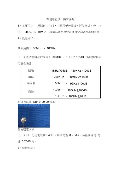
微波暗室内景
(三)归一化场地衰减± 4dB ,场均匀性0~6dB ,多径损耗均匀性±0.25dB 内。
3、结构组成:
(一)屏蔽室:屏蔽室由屏蔽壳体、屏蔽门、通风波导窗及各类电源滤波器等组成。
根据用户要求,屏蔽壳体可采用焊接式或拼装式结构均可。
(二)吸波材料:
1、单层铁氧体片:工作频率范围30MHz ~1000MHz 。
2、锥形含碳海绵吸波材料:锥形含碳海绵吸波材料是由聚氨脂泡沫塑料在碳胶溶液中渗透而成,具有较好的阻燃特性。
(三)其它:主要有信号传输板、转台、天线、监控系统等。
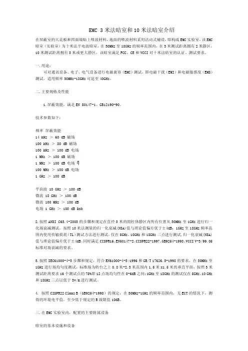
EMC 3米法暗室和10米法暗室介绍在屏蔽室的天花板和四面墙贴上吸波材料,地面的吸波材料采用活动式铺设,即构成EMC实验室。
该EMC 暗室(实验室)为十米法半电波暗室,在30MHz至18GHz的频率范围内,在3米测试距离拥有2米静区,10米测试距离拥有3米或更大静区,该暗室满足FCC、CE和VCCI对十米法暗室的认证、测试要求。
一.用途:可对通讯设备、电子、电气设备进行电磁兼容(EMC)测试,即电磁干扰(EMI)和电磁敏感度(EMS)测试。
适用频率30MHz-18GHz可延至40GHz。
二.主要规格及性能1.屏蔽效能,满足EN 50147-1、GB12190-90。
技术参数如下:频率 屏蔽效能14 kHz > 60 dB 磁场100 kHz > 80 dB 磁场100 kHz > 100 dB 电场1 MHz > 100 dB 磁场1 MHz > 100 dB 电场100 MHz > 100 dB 电场1 GHz > 100 dB平面波 10 GHz > 100 dB微波 18 GHz > 100 dB微波 100 MHz > 100 dB电场 1 GHz > 100 dB &nb2.按照ANSI C63.4-2003的步骤和规定在直径3米的圆柱体静区内所有位置从30MHz至1GHz进行归一化场衰减测试,按照10米法测量的归一化衰减(NSA)值与理论值偏差优于±4dB;1GHz至18GHz频率范围内使用传输损耗(TL)测试方法进行测试,仅在5GHz、10GHz和18GHz三点进行测试,归一化衰减(NSA)值与理论值偏差优于±4dB。
同时满足CISPR16、EN50147-2、CISPR22-1997、GB9254-1998、VCCI V-3/99.05标准对场衰减的要求。
3.按照IEC61000-4-3步骤和规定,符合EN61000-4-3:1996和GB/T 17626.3-1998的要求,在30MHz至1GHz进行场均匀度测试,标准场为转台之上0.8米-2.3米范围内1.5米x1.5米的垂直平面,按照3米测试距离要求16个测试点的75%即12点场均匀性在0-6dB之间;1GHz至18GHz的测试仅在5GHz、10 GHz 和18GHz三点以低于3v/m进行测试。

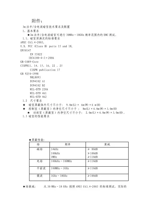
附件:3m法半/全电波暗室技术要求及配置1、基本要求★3m法半/全电波暗室可进行30MHz~18GHz频率范围内的EMC测试。
1.1、暗室须满足的标准要求ANSI C63.4-2003,U.S. FCC (Class B) parts 15 and 18,EN50147EN 55022IEC6100-4-3-2006GR-1089-CoreCISPR11,14,15,16,22 ,25CISPR publication 17GB 9254-1998NRL8093DIN4102 A1DIN4102 B2MIL-STD 220AMIL-STD 461MIL-STD 4621.2 尺寸要求★暗室屏蔽体外尺寸不小于: 9.0m(L)× 6m(W)×6 m(H)★控制室(屏蔽室)内净空尺寸不小于: 8m(L)×4.0m(W)×3.0m(H) ★功放室(屏蔽室)内净空尺寸不小于: 2.0m(L)×4.0m(W)×3.0m(H),1.3 暗室的性能要求★场衰减:从30 MHz~18 GHz 按照ANSI C63.4-2003 的标准测试,实际的NSA 和理论的NSA相比优于± 3.5 dB ,符合美国. FCC Class B(3m)和国际标准。
★静区:在30MHz ~1GHz 频率范围内严格按照ANSI C63.4-2003标准进行测试,在3 米测试距离,有一个直径2 米的圆柱体静区。
在静区内进行归一化场衰减测试的NSA 值和理论的NSA 值相比优于±3.5dB★场地电压驻波比:从1GHz - 18 GHz 按照CISPR16-1-4 ED2 2006和CISPR/A/710 FDIS,直径2米,高2米的圆柱体静区,测试距离3m,两个高度,两个极化方向场地电压驻波比优于6dB。
★场均匀度:从26MHz~18GHz 的频率范围内16 个测试点中的12 个点的均匀性为0~+6 dB,标准场为转台之上0.8m~2.3m 范围内1.5m× 1.5m 的垂直平面★背景噪声:暗室内空间环境的背景噪声(暗室内转台、天线升降塔、照明灯和电视监视器等设备开启状态)测试电平比在30MHz~1GHz的频率范围内的EN55022、GB9254 标准所规定B 级的限值的电平至少低20dB,1GHz~6GHz电平低于6dB。
3m法电波暗室方案英文Title: 3M Method Electromagnetic Dark Room SolutionIntroduction:The 3M Method, also known as the 'Magnetized, Metalized, and Meshed' method, is a highly effective solution for creating an electromagnetic dark room. An electromagnetic dark room is a controlled environment designed to eliminate external electromagnetic interference, enabling precise testing and measurement of electronic devices and equipment. This article will delve into the details of the 3M Method and its benefits.Magnetized:The first step in implementing the 3M Method is magnetization. This involves strategically placing magnets around the perimeter of the dark room. The magnets create a magnetic field that acts as a shield against external electromagnetic waves. By neutralizing the magnetic field, the 3M Method prevents any external electromagnetic interference from entering the dark room.Metalized:The second step of the 3M Method is metalization. The walls, ceiling, and floor of the dark room are coated with a layer of highly conductive metal, such as copper or aluminum. This metalized coating acts as a Faraday cage, enhancing the shielding capability of the dark room. The metal layer reflects and absorbs external electromagnetic waves, preventing them from penetrating the room and affecting the measurements or tests conducted inside.Meshed:The final step of the 3M Method is meshing. Fine mesh screens are installed on windows, doors, and ventilation systems of the dark room. These mesh screens act as additional barriers against electromagnetic waves, allowing the controlled environment of the dark room to remain undisturbed. The mesh screens are designed to have a specific mesh size that blocks the passage of electromagnetic waves while allowing air circulation and visibility.Benefits of the 3M Method:1. Enhanced Accuracy: By creating an electromagnetic dark room using the 3M Method, researchers, engineers, and scientists canachieve highly accurate test results and measurements. Eliminating external electromagnetic interference ensures that the data obtained is reliable and consistent.2. Confidentiality: The 3M Method provides an added layer of confidentiality by preventing any external interference that could compromise sensitive information or intellectual property. This makes it an ideal solution for research and development facilities or companies dealing with proprietary technologies.3. Compliance: Certain industries, such as aerospace, telecommunications, and healthcare, require strict compliance with electromagnetic compatibility regulations. The 3M Method ensures that the testing processes meet these standards, allowing companies to avoid costly penalties and legal issues.Conclusion:The 3M Method provides an effective solution for creating an electromagnetic dark room, enabling accurate and reliable testing and measurements of electronic devices and equipment. By magnetizing, metalizing, and meshing, the dark room becomesshielded from external electromagnetic waves, ensuring a controlled environment. The benefits of implementing the 3M Method include enhanced accuracy, confidentiality, and compliance with industry standards.。
技术文件3m法电波暗室辐射场抗扰度场地均匀性校准规程The method of uniform field strength calibration in 3mchamber第一版The 1st edition批准:日期:审定:日期:编制:日期:2009.05.20 QJ/63.740-20091 适用范围和目的Scope and object:IEC61000-4-3测试中的场地均匀性校准The calibration of field in IEC61000-4-32引用文件Normative referencesIEC 61000-4-3:1998电磁兼容试验和测量技术射频电磁场辐射抗扰度试验Testing and measurement techniques- Radiated, radio-frequency, electromagnetic field immunity test3校准使用的仪器设备:Test equipment:①3m法电波暗室Anechoic chamber②射频信号发生器RF signal generators:③宽频功放power amplifier④发射天线 field generating antennas⑤场强探头 field strength monitoring antenna⑥场强仪 field strength monitor⑦功率仪 power meter4 校准过程:a) 场强探头位置的确定Locate the field strength probe position确认IEC61000-4-3标准测试中所使用垂直均匀域平面,定出需要校准的16个点的位置; Locate the vertical uniform area and the 16 measuring point for calibration as following:Figure11111 12131421 22 23 2431 32 34 33 41 42 43 44测试中,场强探头应放置在如图1所示的16个点上,其中场强探头的垂直投影应分别落在图2所示的地面上的1、2、3、4点上,如图2;场强探头的高度应在图3所示的1、2、3、4位置:During the test, the field strength probe should be put in the 16 poison as shown in figure1,the vertical projection of the probe should located on position 1 to 4 on the ground as shown in figure 2, and the height of the probe should be at position 1 to 4 in figure 3.Figure22 34 14321 Figure 3b)吸波材料位置的确认Locate the absorber position在地面上铺设使用的吸波材料,记录吸波材料的配设位置, mark1至mark4分别为吸波材料铺设的4个角;Put additional absorber on the ground, and record the position of the 4 angle of the absorber as in figure 4:Mark 3Mark4 Mark 2Mark 1Figure 4c)将天线放置在距离垂直均匀域平面3m远的位置处Put the antenna on the point 3m away from uniform field area and make sure the direction of the antenna perpendicular to the uniform field area as in figure 5:Uniformfield area3mFigure 5d) 天线水平位置的定位Locate the horizontal position of the antenna分别记录天线水平极化的天线四角在暗室地面的上垂直投影点H1、H2、H3、H4及天线底座三脚所在位置1、2、3,同时记录天线四角距地面的高度h H 如图所示;Record the horizontal position of the antenna as in figure 6, the vertical projection of the 4 angel of the antenna are marked as H1 to H4, and the position of the tripod are marked as 1 to 3. The heights of the 4 antenna angel are also recorded.Figure 6123H1H2H3H4h He) 天线垂直位置的定位Locate the vertical position of the antenna分别记录天线垂直极化的天线四角在暗室地面的上垂直投影点H1、H2、H3、H4及天线底座三脚所在位置1、2、3,同时记录天线四角距地面的高度h v.如图所示;Record the vertical position of the antenna as in figure 7, the vertical projection of the 4 angel of the antenna are marked as V1 to V4, and the position of the tripod are marked as 1 to 3. The heights of the 4 antenna angel are also recorded.Figure7f) 连接电缆的定位Locate the connection cable连接电缆,并记录电缆途径关键点,如下图;Connect the signal cable to the antenna, and the point where the cable pass by should be record as in figure8:31 2V1V2V3V4H VFigure 8g)从80MHz开始,将场强探头放在某一均匀域测量点上(如22位置),给天线供以一定前向功率信号Pc,使得在场强探头上测得的场强值约为所需计量的场强值Ec(如10V/m)Position the sensor at one of the 16 points in the grid ( for example 22), and set the frequency of the single generator output to the frequency 80MHz. Apply a forward power to the field-generating antenna so that the field strength obtained equals Ec(for example 10V/m).Record the forward power and field strength readings.h)以1%的前一频率为步长,重复步骤g),直到频率到达1GHz,生成的频率和输入前向功率的表格如下:Increase the frequency by 1% of the present frequency, and repeat step g) until the frequency reach 1GHz. The forward power and the field strength reading should be record in table 1.Table 1i)将探头分别移到移到网格中的其他15个位置,给天线供以上表1中的前向功率的信号Pc,记录15个点上测量的每个频点上的实测场强,记录在下表中;Move the sensor to other 15 positions in the grid. At each of position, the forward power in table1 should be used. And the measure field strength should be recorded in table 2Table 25数据处理:The calculating procedure:a)将表2中的测量场强值按从低往高排列,如表3;Sort the 1 field strength into ascending order as in table 3:From low to hightable3b)分别计算从小到大连续12个场强的最大场强差值R1至R5;Calculate the field strength deviation R1 to R5 of continuous 12 point from low to high as following formula, and the data should be recorded in table 4:R1=20log(e12/e1) R2=20 log(e13/e2) R3=20 log(e14/e3)Table4c)场强差值从R1向R5,第一个小于6dB的值对应的最小场强值(表4中)作为场地均匀性校准的参考场强E T,并记录在下表中:Check the field strength deviation R1 to R5, the first one less than 6dB should be marked andTable 5d) 利用下列公式得到测试场强E C 所对应的前向功率P c ;Calculate the calibration forward powers as following formula, and record them in talbe6:)/log(20t c t c E E P P +=Table 6。
3米法电波手机测试EMC 暗室基本配置要求3米法暗室是一个最新设计的EMC 测试场地,主要用于辐射发射和辐射敏感性的标准性测试。
整个的系统具有多功能用途,覆盖国际、欧洲、美国和各国的标准。
用途3米法暗室是一个最新设计的EMC 测试场地,主要用于辐射发射和辐射敏感性的标准性测试。
整个的系统具有多功能用途,覆盖国际、欧洲、美国和各国的标准。
本场地在3米法的测试距离里能够测试电信设备、家用电器、汽车元件、工科医设备 (ISM)以及信息技术设备 (ITE) 。
3米法的暗室也同样地可以获得 FCC facility, European accreditation 和 VCCI recognition 的认可。
此3米法暗室完全符合一般性的标准, 同时它的频率范围可以提高到 18 GHz 。
在屏蔽和吸波材料,使用了最先进的模块系统,已安装的暗室可以拆迁,再安装或扩充,来适应新的标准。
发射对于标准性测试,研发阶段和质量控制的辐射发射测试在3米法的暗室内进行已完全可以胜任。
它符合EN 50147-2 1996 和 ANSI C63.4 1992标准,具有直径2.0米的空间静区。
另外,作为选件这个3米法的场地也可以选择提高到18 GHz 的频率范围。
抗干扰本3米法的暗室在辐射抗干扰测试里同样有优越的性能。
在 1.5 x 1.5 米平面内, 3米的测试距离, 能精确的达到 IEC 1000-4-3 1995 和 EN 61000-4-3 1996 标准。
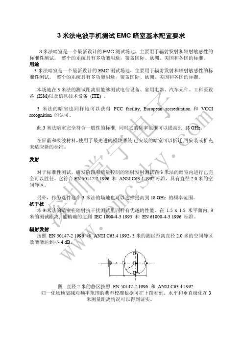
辐射发射按照 EN 50147-2 1996 和 ANSI C63.4 1992,3米的测试距离直径2.0米的空间静区效能能达到+/- 4 dB 。
图: 直径2米的静区按照 EN 50147-2 1996 和 ANSI C63.4 1992归一化场地衰减对频率范围的典型校准数据可在下图看到。
水平和垂直极化在3米测量距离情况可以得到证实。
深圳常宁电子 w w w .e m c s k y .c o m辐射敏感度准确达到 IEC 1000-4-3 1995 和 EN 61000-4-3 1996 标准, 在1.5 x 1.5 米平面, 3米的测试距离, 要求 75% 的 16 点在0 … +6 dB 之内的 准确性。
1、测试系统应用范围:
1.13m法全电波杂散测试系统技术参数
测试系统符合ETSI EN 301489,FCC Part 15 标准的要求
测试带宽为100KHz至40GHz
对被测设备的天线端口进行传导杂散发射测量(100 kHz 至12.75 GHz)
30 MHz 至40 GHz辐射杂散测试
自动杂散测试系统覆盖30MHz-18GHz
1.2 3m法全电波暗室技术参数:
1.屏蔽效能:测试频率范围为10kHz~18GHz时应大于80dB。
2.自由空间归一化场地衰减(NSA):30MHz~1GHz:在3m测试距离,位于地面吸波材料,直径1.5m,高度1.5m的静区内,暗室自由空间归一化场地衰减与理论值偏差优于±
3.5dB。
3.场均匀性:30MHz~18GHz: 在转台之上0.8m高的1.5m×1.5m 的垂直平面,16个测试点中75%的点场地均匀性在0~+6dB之间。
4.场地电压驻波比:1GHz~18GHz: 测试距离3米,测试直径1.5m,高度1.5m的静区驻波比≤
5.5dB。
5.背景噪声:30MHz~18GHz: 在无EUT的情况下,测试电平应比CISPR22所规定B级的限值的电平至少低10dB(峰值);
6.自由空间传输损耗偏差:小于±4dB
2、主要设备
2.1无线通信综测仪及配套设备
2.2天线及配套附件
2.3电磁兼容系统软件
2.4 电波暗室及主要部件。
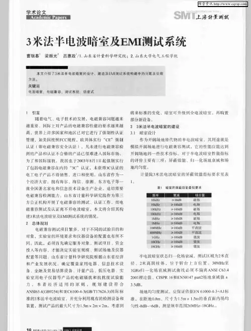
电波暗室的建设文章通过对电波暗室建设的经验介绍,阐述在电波暗室建设过程中我们应该关注的一些主要问题,从而去除施工过程中出现可以避免的疏漏。
标签:电波暗室;建设;注意事项引言电波暗室主要用于提供电磁兼容测试所需要的标准环境,是提高测试一致性和可重复性最基本手段。
传统上,这种环境可以通过建造开阔测试场(OATS)来完成。
随着空间RF信号的增多,很难得到良好背景的OATS,因此国内外标准都推荐采用电波暗室来取代OATS。
电波暗室由于电磁环境稳定、温湿度可控且不受外界气候的影响而逐渐成为当前使用最为广泛的电磁兼容测试场地。
建造一个电波暗室需要考虑的因素很多,各公司、企业或检测机构具体情况千差万别,因此建造的电波暗室也各不相同。
那么建造电波暗室应关注哪些因素呢?1 电波暗室规划电波暗室又分为3米法、5米法和10米法标准电波暗室,各公司、企业或检测机构可根据自身的资金情况、可利用土地面积、常用测试对象尺寸,选择适合的电波暗室,国际标准一般规定频率范围为30MHz~18GHz,主要指标有:屏蔽效能、场地均匀性,归一化场地衰减和传输损耗,驻波比(Svswr)等。
2 电波暗室的建造电波暗室在建造的过程中会涉及以下几个比较重要的方面。
2.1 场地的选址和土建建造一个电波暗室,如何选址也是一个学问,一般建议暗室建设在地面一楼,除了要考虑到测试对象的搬运以外,良好并尽量短的接地也是我们必须考虑的重要环节。
在场地设计时我们可以采用下陷式,这种设计的好处是完工以后暗室的地面与周围齐平,有利于测试对象的搬运甚至整车的进场,但这种设计的缺点是防潮防水比较困难,另外一种设计刚好相反,可以做成一个加高的平台。
在场地的建设之前我们必须对所选场地的地质进行评估,如果地质情况比较差,还得通过打桩等措施加固,防止日后由于承重问题的地面下陷。
暗室安装地面也有平整度要求,一般是要求3米乘3米范围内高差小于3毫米,不允许有累计误差,地面不得朝一个方向倾斜。
设计建造EMC暗室(标准3米法)目录第一部分公司简介 (2)第二部分桐邑公司设计、建造EMC暗室的优势 (3)第三部分EMC暗室立体剖面图……………………………………………… 4-5第四部分EMC暗室项目设计书……………………………………………6-28一、EMC实验室的主要规格和指标…………………………………………… 8-9二、EMC实验室的基本配置与建设…………………………………………… 10-14三、EMC测试软件……………………………………………………………… 15-24四、EMC实验室的验收 (25)五、传导屏蔽室的基本配置与建设 (26)第五部分培训 (27)第六部分暗室价格 (28)第七部分超值服务 (29)第八部分相关条款 (30)第九部分施工组织方案及保修条款……………………………… 31-32附录一屏蔽效能测试报告………………………………………………… 33-37附录二场衰减测试报告…………………………………………………… 38-39附录三场均匀测试报告…………………………………………………… 40-42附录四滤波器简介 (43)附录五铁氧体瓦简介……………………………………………………… 44-47第一部分:公司简介桐邑科技于2003年7月正式进入中国大陆市场,秉承国际的品质、国内的价格的原则,迅速赢得用户的信赖。
目前桐邑公司可为用户提供从暗室设计建造、测试设备规划及人员培训等一条龙服务中国大陆案例众益集团协隆电子03年东莞精成电子集团04年大连大显集团04年苏州大学04年深圳中天讯05年中国质量认证中心(CQC)中认实验室05年中怡电子(苏州)研发中心05年康硕电子(东莞)05年番禺得意精密电子工业06年讯创(天津)电子06年斯凯威科技(北京)06年辐远科技(东莞)06年广州奥杰电子06年第二部分桐邑公司设计、建造EMC暗室的优势桐邑公司设计、建造的暗室屏蔽壳体是严格遵守美国标准NSA 65—6中规定的屏蔽效能,同时符合EN50147-1和GB12190-90标准的要求。
附件1项目需求及技术要求13米法电波暗室一套以及本项目所需技术设备的采购、运输、设计、安装、调试、检验、检定、校准以及售后服务等全部相关工作。
2、总体要求2.1 暗室须满足的基本要求本3米法半/全电波暗室可进行10kHz~40GHz频率范围内的EMC测试,本项目应满足开展低压电器、工科医设备(ISM)、信息技术设备(ITE)、家用电器、电气照明、音视频产品、电视广播设备、汽车零部件、无线通信设备以及电力系统设备等各种产品全部EMC测试工作的要求。
该暗室主体及附属装置需经甲方认可的第三方权威机构测试校准合格,其技术指标必须符合相关国际和国家现行标准,并满足CNAS认可的要求。
2.2 项目须满足的标准要求电波暗室的设计和制造必须符合以下标准的最新版本。
电波暗室的屏蔽效能应符合标准EN50147-1(GB/T12190 )的要求。
电波暗室的归一化场地衰减应符合标准ANSI C63.4、CISPR16-1-4、GB/T6113.104的要求。
电波暗室的场均匀性应符合标准IEC61000-4-3 、EN61000-4-3的要求。
电波暗室的场地电压驻波比应符合标准CISPR16-1-4 、CISPR16-2-3的要求。
电波暗室的环境噪声应符合标准CISPR22(GB9254)、CISPR11的要求。
电磁兼容项目可以完成以下国际国内现行最新标准的测试:CISPR11(GB 4824)《工业、科学和医疗射频设备射频干扰特性的测量方法和极限》CISPR13 (GB 13837)《声音和电视接收机的射频干扰特性的测量方法和极限值》CISPR14-1 (GB 4343.1)《电磁兼容家用电器、电动工具和类似器具的要求第一部分;发射》CISPR14-2(GB 4343.2)《电磁兼容家用电器、电动工具和类似器具的要求第一部分;抗扰度》CISPR15 (GB 17743)《电气照明和类似设备的无线电骚扰特性限值和测量方法》CISPR16 (GB/T 6113)《射频干扰测量装置和测量方法的规范》CISPR17(GB 7343)《无源无线电干扰滤波器和抑制元件抑制特性的测量方法》CISPR19(GB/T 16607)《微波炉在1GHz以上辐射干扰测量方法》CISPR20(GB/T 9383)《声音和电视广播接收机及有关设备抗扰度限值和测量方法》CISPR22(GB 9254)《信息技术设备的射频干扰特性测量方法和极限值》CISPR24(GB 17618)《信息技术设备的抗扰度限值及测量方法》CISPR25(GB 18655)《车辆、船只或相关设备中接收器的无线电干扰性能限值和测试方法》IEC61000-4-3( GB/T17626.3)《电磁兼容性试验和测量技术射频电磁场辐射抗扰度试验》GB/T 17626 《电磁兼容试验和测量技术》GB/G 17619 《机动车电子电器组件的电磁辐射抗扰性限值和测量方法》ISO11452、ISO7637 、IEC 61547 /EN 61547、IEC60945 、IEC 60947-2(GB14048.2)、GJB151A (MIL-STD-461D) 、GJB152A (MIL-STD-462D)、CISPR publication 17、GR-1089-Core、CISPR/A/710 FDIS、MIL-STD 220A等。
一、简介电波(半)暗室是面向公司交换、接入、SDH、ETS、GSM、数据终端、STP、电源及监控等产品的电磁兼容测试要求而建设的。
电波暗室的技术指标必须符合归一化场地衰减NSA±3.5dB(30MHz~18GHz),场均匀性(0,+6dB)的要求(30MHz~18GHz)。
从而使组建的测试系统具有高效、先进及高性价比的特点。
二、电波暗室总体技术指标要求所有进行验收测试系统中设备需符合CISPR16标准要求。
在屏蔽室建设完成,安装吸波材料或其他装修前,完成屏蔽效能的测试。
在整个电波半暗室完成后,完成规一化场地衰减NSA、场地均匀度和背景噪声测试。
所有以上四项测试必须由我方认可的第三方进行。
电波半暗室应满足以下指标:1)归一化场地衰减NSA3M法暗室可确保在直径为2M的静区内从30MHz至1GHz测量的归一化位衰减(NSA、Normalized site Attenuation)与理论值偏差不超过±3.5dB(标准要求±4.0dB),符合ANSI C63.4--1992,CISPR16,EN50147-2的要求。
2 )传输损耗TL3M法暗室可确保在直径为2M的静区内从1GHzHz至18GHz测量的传输损耗与理论值偏差不超过±3.5dB(标准要求±4.0dB),符合ANSI C63.4--1992,CISPR16,EN50147-2的要求。
3)场地均匀度3M法暗室必须符合从80MHz至2GHz频率范围内测试区的场地均匀性达到(0,+6dB)的要求,符合1EC61000-4-3和EN61000-4-3的要求。
4)屏蔽效能3M法暗室及屏蔽控制室必须按照EN50147-1进行测试,屏蔽效能至少能满足如下要求:频率屏蔽效能10KHz--150KHz 70dB(磁场)150KHz朹1MHz100dB1MHz--1000MHz110dB1GHz--18GHz100dB三、电波暗室的系统组成及要求1、电波暗室配置及要求1)供应商按照我方的要求完成吸波暗室的设计2)供应商完成屏蔽室的建造提供屏蔽尺寸不小于:9.1m×5.8m×5.55m建筑结构为:拼装式结构暗室与周围大地应有大于10M欧姆的阻抗隔离。