50K音量电位器RK08H113003G选型手册
- 格式:pdf
- 大小:484.67 KB
- 文档页数:4

Current Measurement SystemsAM5030 •AM5030SOur most up-to-date product information is available at:Copyright © 2005,Tektronix,Inc.All rights reserved.Tektronix products arecovered by U.S.and foreign patents,issued and rmation in this publi-cation supersedes that in all previously published material.Specification and pricechange privileges reserved.TEKTRONIX and TEK are registered trademarks ofTektronix,Inc.All other trade names referenced are the service marks,trade-marks or registered trademarks of their respective companies.1/05 DV/WOW51W-10226-3 you can configure and confirm thesettings of the amplifier or read theinstrument’s serial number. You candetermine whether the current probe isopen or closed, use bus commands toinitiate a self-test or force a probeDegauss and DC balance operation. TheAM5030 bus address is set through thefront panel and the address is retainedwhen power is removed. The AM5030does not require an external controller tooperate. It can be completely controlledusing the front panel; however, whenused with a controller, the front panelcan be disabled to prevent manualoperator adjustments.AM5030SThe AM5030S consists of an AM5030and a TM5003. If you already own apower module, order only an AM5030.If you need a power module, order anAM5030S. Order the appropriateprobes separately.Ordering InformationAM5030Programmable Current Probe Amplifier.Includes:50ΩBNC cable (012-0057-01);instruction manual (070-8766-05); reference card(070-8770-01).The AM5030 requires an A6312,A6302,A6303 or XL Series Current Probe and aTM5003 or AM5030S Power Module Mainframe.Please specify power cord when ordering.AM5030SProgrammable Current Probe Amplifier andPower Module.Includes:AM5030 Programmable Current ProbeAmplifier and TM5003 3-wide Power ModuleMainframe.Order probes separately.Pleasespecify power cord when ordering.International Power PlugsOpt. A0 –North America power.Opt. A1 –Universal EURO power.Opt. A2 –United Kingdom power.Opt. A3 –Australia power.Opt. A4 –240 V,North America power.Opt. A5 –Switzerland power.ServiceOpt. C3 –Calibration Service 3 Years.Opt. C5 –Calibration Service 5 Years.Opt. D1 –Calibration Data Report.Opt. D3 –Calibration Data Report 3 Years(with Opt.C3).Opt. D5–Calibration Data Report 5 Years(with Opt.C5).Opt. R3 –Repair Service 3 Years.Opt. R5 –Repair Service 5 Years.Contact Tektronix:ASEAN / Australasia / Pakistan (65) 6356 3900Austria +41 52 675 3777Balkan,Israel,South Africa and other ISE Countries+41 52 675 3777Belgium07 81 60166Brazil & South America55 (11) 3741-8360Canada1 (800) 661-5625Central East Europe,Ukraine and Baltics+41 52 675 3777Central Europe & Greece+41 52 675 3777Denmark80 88 1401Finland+41 52 675 3777France & North Africa+33 (0) 1 69 81 81Germany +49 (221) 94 77 400Hong Kong(852) 2585-6688India(91) 80-22275577Italy+39 (02) 25086 1Japan81 (3) 6714-3010Luxembourg+44 (0) 1344 392400Mexico,Central America & Caribbean52 (55) 56666-333Middle East,Asia and North Africa+41 52 675 3777The Netherlands***********Norway800 16098People’s Republic of China86 (10) 6235 1230Poland+41 52 675 3777Portugal80 08 12370Republic of Korea82 (2) 528-5299Russia,CIS& The Baltics7 095 775 1064South Africa+27 11 254 8360Spain (+34) 901 988 054Sweden020 08 80371Switzerland+41 52 675 3777Taiwan886 (2) 2722-9622United Kingdom & Eire+44 (0) 1344 392400USA1 (800) 426-2200USA(Export Sales) 1 (503) 627-1916For other areas contact Tektronix,Inc.at:1 (503) 627-7111Last Updated 3 November 2004。


Contents目 录Appearance外观说明---------------------------------------------1Product Features产品特点---------------------------------------------1Installation Notes and Conditions of Usage安装注意事项及使用条件--------------------------------3Installation Steps安装步骤说明-----------------------------------------4Product Selection Table产品选型表-------------------------------------------5Control Mode and Application Load控制方式及适用负载------------------------------------7Wiring and Layout Considerations配线及布局注意事项------------------------------------7Terminal Wiring端子接线说明-----------------------------------------8Load and the Controller Wiring Diagram负载接线图和控制器接线图------------------------------9Product Parameters产品参数--------------------------------------------10Product Dimensions产品尺寸示意图--------------------------------------11Appendix :Electric Heating Wiring Diagram Examples附录:电加热接线实例图Product Pictures产品图片示例----------------------------------------12Thyristor power regulator is one kind of digital power controller,which is based on power semiconductor module (SCR ) and the digital processor core technology .It is also called Voltage Regulation for short .As a result of phase angle control and zero crossing control technology, the products has intelligence integration of voltage and power regulation significant features.可控硅电力调整器是一种以电力半导体模块(晶闸管)为基础,以数字处理器技术为核心的数字电力功率控制器。

VICTORY V50 ‘The Earl’All Valve 50 Watt Guitar Head User Guide• Do not use this amplifier near water or any other liquid• Do n ot block any openings• Do not attempt to clean the amplifier with any fluids: use only a dry clothDo not attempt to modify or service this product yourselfRemoving covers could mean you are exposed to dangerous voltages that may result in severe injury or death• Refer all servicing to qualified service personnel• Damage Requiring Service: Unplug this product from the wall outlet and refer servicing to qualified service personnel under the following conditions:(a) When the power-supply cord or plug is damaged;(b) If liquid has been spilled, or objects have fallen into the product;(c) If the product has been exposed to rain or water;(d) If the product does not operate normally by following the operating instructions. Adjust only those controls that are covered by the operating instructions. Improper adjustment of other controls may result in damage and will often require extensive work by a qualified technician to restore the product to its normal operation;(e) If the product has been dropped or damaged in any way;(f) When the product exhibits a distinct change in performance - this indicates a need for service. Replacement Parts: When replacement parts are required, be sure the service technician uses replacement parts specified by the manufacturer or have the same characteristics as the original part. Unauthorized substitutions may result in fire, electric shock, or other hazards.InputPlug your guitar in here!when you want to introduce more natural valve overdrive to your tone.Balancing your input gain level with your master volume level is crucial in delivering the tone and feel that works best for you.Pull CrunchThe Clean Gain control incorporates a pull-switch. This can be used to introduce more gain into the Clean Channel for Crunchy rhythm playing or just to add a bit more character to the clean sound. The amount of ‘Crunch’ will vary depending on how much Clean Gain is dialed in.Channel Select SwitchThe V50 has two channels that you can switch between using this front-panel toggle, or a remote footswitch plugged into the Channel/Boost footswitch socket.The clean channel is selected by switching the selector to the left.Overdrive GainExactly the same a s the clean channel, this controls the input gain… except here there’s a whole load more of it! Run it lower for crunchy sounds, in the mid-range for thicker overdrive, and crank it up for the fullest distortion.BoostThe overdrive channel in the V50 also has a switchable gain boost, which is accessible via the footswitch or front panel toggle switch. It enables you to go from crunchy rhythm guitar to sustaining lead guitar tones.Overdrive ReverbUse this control to adjust the amount of Reverb on the Overdrive channel.HIGH – STANDBY – LOW SwitchThe V50 should always be switched on, (mains switch on front of amplifier), with this front panel toggle switch in its centre position. The amplifier is now in ‘STANDBY’ mode with just the valve heaters and low voltages on. This allows the valves to heat up before they get 100s of volts up th em, (it’s less of a shock). After around 60 seconds, the amp can be switch to either HIGH, (around 50 Watts rms) or LOW, (around 15 Watts rms). To extend valve life, the amplifier can be switched to ‘Standby’ when not being played. REAR PANELVoltage selectorSelects the correct mains voltage for your territory. Please refer to a qualified technician before even thinking about moving this switch. If you do find yourself in foreign climes where the mains voltage is different to home, (and the water tastes funny), it will be necessary to switch this selector. The mains fuse must always be changed at the same time. Failure to do this will result in either the mains fuse blowing as soon as the amp is turned on or the amp running with a fuse that is of too higher value tovalve are shorted and in this case the amplifier needs to be checked by a qualified engineer to assess the problem.Speaker OutputsPLEASE NOTE: The lightning flash with arrowhead symbol, within an equilateral triangle, is intended to alert the user to the presence of uninsulated ‘dangerous voltage’ within the product’s enclosure that may be of sufficient magnitude to constitute a risk of el ectric shock. Terminals labelled as “Speaker Outputs” must be connected to a speaker cabinet of the designated load rating using an un-shielded two conductor cable for speaker use at all times during operation. Never use a guitar cable to connect the ampli fier to a speaker as this presents the amplifier with a ‘capacitive load’. This can cause instability or oscillation which may seriously damage valves and/or the expensive output transformer.Never run the amplifier without a load connected or serious damage to the output transformer may occur.The output transformer in the V50 has 3 separate secondary windings; a 4 Ohm, an 8 Ohm and a 16 Ohm. This makes it easy to connect many different combinations of speakers. There are five speaker output jacks: 2 x 4 ohms, (wired in parallel), 2 x 8 ohms, (wired in parallel) and 1 x 16 ohms.So here are all the possible combinations:For a single 4 Ohm cabinet, use either of the 4 Ohm sockets.For a single 8 Ohm cabinet, use either of the 8 Ohm sockets.For a single 16 Ohm cabinet, use the 16 Ohm socket.amplifier is a rubbish way to die.Also take care as valves may still be very hot from use.Please always try to buy matched sets of output valves as they will be easier to Bias and give longer service. Ensure the toggle switch on the top of the chassis is in the correct position for the selected output valves, (either 6L6s or EL34s). Toggle towards output valves for 6L6s.Unplug the V50 from the mains; remove the rear grill and the 4 retaining bolts on the underside. Carefully slide the chassis from the wooden sleeve and place it on a clear and secure surface upside down so all its soft bits are exposed. Take care not to damage the output valves when turning the amp over.The BIAS pre-set is found on the power supply PCB, (see yellow circle on photo). The best place to take a Bias voltage measurement is across each one of the two 1 Ohm resistors that are fixed between the chassis and Pins 1&8 on the output valve ceramic bases (see yellow squares on photo).Using a multimeter set on the 200mV range, measure across each of these resistors in turn and adjust the BIAS preset so the meter reads between 32 and 40mV. This translates into 32-40mA of current per output valve so each valve is biased at between 32 & 40mA, (34mA is a good figure to aim for). Check both resistors a few times and try to balance the Bias voltage so it is as close as possible between the 2 pairs. We don’t recommend a difference of greater than 6mV between each valve.A note from Team VictoryWe’ve built your Victory Amplifier as a professional, no-compromise musical instrument, with a great deal of pride and an absolute commitment to tone. We encourage you to learn to get to know it by experimenting with all the controls, in order to discover its vast array of tonal combinations.Thank you for making your tones with us: we wish you many years of achieving inspiring sounds to push your playing ever onwards.I’ll shut up; you go play yer guitar.Team VictoryContact info: ************************.ukWeb: /user/VictoryAmps/VictoryAmpsUK。
3G-β3-EC-130412-001User ManualDIGITAL SPEAKER CONTROLLERC880024 BIT DIGITAL CROSSOVER SYSTEM PROCESSOR12345678LIMITER MUTE -6-10OVER -20COMP MUTE-6-10OVER -20INPUT OUTPUTLIMITERMUTE-6-10OVER -20Para12345678C8800122233444412131. CAUTION 2. INTRODUCTION 2.1 Main Features 3. PACKAGE4. AC POWER REQUIREMENTS5. FRONT PANEL CONTROL FEATURES6. REAR CONNECTING FEATURE7. .DISPLAYS AND OPERATION 7.1 Main Menu7.2 Browse Configuration Program 7.3 Call the Configuration Program 7.4 Modify ID Number8. BUILT-IN SIGNAL PROCESSING 9. SOFTWARE10.DEFINITION OF PORT 11.SPECIFICATIONSTABLE OF CONTENTS6679 9.1 How to Get this Software9.2 Facility and the Connection of Computer. 9.3 Instruction of PC Software 9.4 Signal Process Module 11 9.5 EQ/Xover Curve 55 8.1 Input Part 8.2 Output Part!Instruction:The lightning flash with arrowhead symbol within the equilateral; triangle is intended to alert the user to the presence of un-insulated “angerous voltage ” within the product's enclosure that may be of sufficient magnitude to constitute a risk of electric shock.The exclamation point within the equilateral triangle is intended to alert the user to the presence of important operation an maintenance (servicing) instructions in the literature accompanying this appliance.Do not open the cover :Do not open the cover to avoid the risk of electric shock caused by high voltage parts in the product. Any problems caused by user's wrong actions are out of warranty.the cord Please hold the plug when pulling out or plug in the cord. Do not pull out or touch the cord with wet hand, or it will cause the risk of electric shock. Power supply cords should be routed so that they are not likely to be walked upon or pinched by items placed on or against them. When removing the cord from a power outlet be sure to remove it by holding the plug attachment and not by pulling on the cord.Avoid object and liquid entry :Abnormal status :Nonuse for a long time :Take care that objects do not fall into and that liquids are not spilled into the inside of the product.If the object or liquid enter the product, please ask qualified personnel to check it.In the event of abnormal noise and smell, please put off the power supply and pull out the cord, please ask qualified personnel to check it.When nonuse it for a long time, please put off the power supply and pull out the cord to avoid the unexpected dangers.Do not damage the cord :1. CAUTION2. INTRODUCTIONThank you for your purchasing of the device digital speaker processor, this processor builds on the advanced and experienced ideas of design and marketing, the excellent audio performance and competitive quality & price ratio make sure your interests.2.1 Main FeaturesThe Device utilizes state of the DSP technologies, beginning with 24bits,48kHz delta-sigma A/D and D/A converters with 32bits floating points DSP. Digital processing includes Gain, Polarity Invert, Parametric EQ, Shelving Filters, Delay, Crossover Functions (Butter worth /Bessel/Linkwitz, optional slope12dB~36/oct),Limiting Functional Module, etc. Each input signal can be passed to another channel by router and can be delayed max 4 seconds.6 way LED signal indicates the status of each input and output dynamic.LCD displayed information of program and device.40 groups of configure programs is available for the user.1 USB communication port is used for connection of PC software and updated the program.Dual RS485 port can be used for connection with more device at large gymnasiumapplication by user3. PACKAGEAs a part of our system of quality control, every product is carefully inspected before leaving the factory to ensure flawless appearance, after unpacking, please inspect for any physical damage, keep the shipping carton and all packing materials, if have any physical damage, please inform you dealer.4. AC POWER REQUIREMENTSBefore connecting your device with your local voltage please make sure your local voltage and AC socket is same or cover this device, if your device doesn't work, normally the reason is fuse broken, please ask help for replacing same fuse by professional person.5. FRONT PANEL CONTROL FEATURES1. USB connection port.2. Input channel mute button3. LCD display.4.Para button for parameter selection or confirmation of menu.5.Up button for parameter selection.6.Down button for parameter selection.7.Output channel mute button8.Input channel signal level indicator and mute status indicator 9.Output channel signal level indicator and mute status indicator6. REAR CONNECTING FEATURE1 Output Signal Terminal2 Input Signal Terminal3 RS485 Input Terminal4 RS485 Output Terminal 5 Power Switch6 Power Input Socket7 Product Serial NumberC880024 BIT DIGITAL CROSSOVER SYSTEM PROCESSOR12345678LIMITER MUTE -6-10OVER -20COMP MUTE-6-10OVER -20INPUT OUTPUTLIMITERMUTE-6-10OVER -20Para12345678①②③④⑤⑦⑨⑧⑥⑦①③④⑤⑥②~230V / 50HzIN OUT RS485POWER OUTPUTINPUTWARNINGRISK OF ELECTRIC SHOCKDO NOT OPENS/N:DONGGUAN 3G AUDIO TECHNOLOGY CO., LTD.87654321876543217. DISPLAYS AND OPERATION7.1 Main Menu. Switch on power, The display will show program name you are using asfollowing:Preset 18x8 Digital Process7.2 Browse Configuration Program. You can browse internal configuration program by up ordown button under main menu as following:Recall: Preset 18x8 Digital Process7.3 Call the Configuration Program.you can call the configuration program by push "para"button under main menu or browse configuration program.Recall Preset 1Are you sure Yes/No ?Select "YES","NO" by up or down button, then push "Para" button to carry out. Select"Yes" showed as following and "No" for back to menu.Recalling...Please Waiting!7.4,Modify ID Number: keep pressing "Para"to modify ID number as following:Modify Device IDID: 01Modify ID number from 1-50 by up or down button, ID number will be savedautomatically when you modified.8. BUILT-IN SIGNAL PROCESSINGThis device equipped with 8 channel input signal port and 8 channel output signal port, anyinput signal can be passed to another output with different ratio.8.1 Input Part1.Five parametric equalizerEQ Type: peaking/bandpass/hi-shelf/lo-shelf/notch.Frequency: 20~20KHz,based on 1/12oct,totally 121 frequency points.Level: peaking/hi-shelf/lo-shelf filtering gain,can be adjusted between -12dB~+12dB,0.5dB/step.Q: peaking/bandpass/notch filtering quality factor,can be adjusted between 0.31~19.4.2.Input Gain(Gain)+12dB~ -90dB adjustment 1dB/step3.Input Channel Delay, Each Channel can be delayed Max 2 seconds4.Input Mute Switcher(Mute)8.2 Output Part1.Signal Route, Any input signal can be passed to any output with different ratio.2.Output Channel Delay(Delay),Max delay for each output channel is 2 seconds, Max delay for each channel is 4 seconds,(input + output delay),can be adjustment separately.3.Crossover(HPF/LPF)Frequency: 20~20KHz,Based on 1/12oct,totally 121 frequency points.Filter Type:2/3/4/5/6 step Butterworth2/3/4/5/6 step Bessel2/4 step Linkwitz-Riley4.Seven parametric equalizer(PEQ)EQ Type: peaking/bandpass/hi-shelf/lo-shelf/notch.Frequency: 20~20KHz,based on 1/12oct,totally 121 frequency points.Level: peaking/hi-shelf/lo-shelf filtering gain,can be adjusted between -12dB~+12dB,0.5dB/step.Q: peaking/bandpass/notch filtering quality factor,can be adjusted between 0.31~19.4。
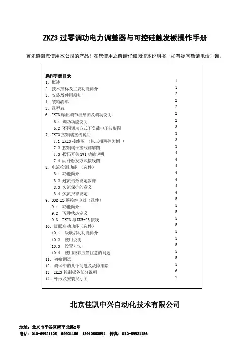
ZKZ3过零调功电力调整器与可控硅触发板操作手册首先感谢您使用本公司的产品!在您使用之前请仔细阅读本说明书,如有疑问敬请电话垂询。
北京佳凯中兴自动化技术有限公司1.概述:ZKZ3过零调功电力调整器是2006年我公司根据市场需求设计开发的新一款电力调整器。
其主要应用于恒阻负载的三相两控的控制方案中。
ZKZ3是一款性能十分出众的电力调整器,可谓本公司又一款经典设计。
ZKZ3除一般过零调功器所具备的通用功能外,还设计了如:级联分时启动、过流保护、负载欠流(包括加热器断线)保护及报警、电流环工作状态发送等一些只在高端产品中才有的功能,使您在设计中可更加得心应手。
ZKZ3主要应用于三相两控、三相三控过零调功电力调整器(详见选型表)。
ZKZ3系列单相调整器由控制板、散热单元、功率模块外壳等组成。
散热系统采用高效散热器、低噪长寿命风机。
输出调节有PWM定周期调功和CYC周波变周期调功种方式供您选择。
2.技术指标及主要功能:⏹功率元件: 进口单向反并联晶闸管模块⏹电流容量: 40、80、150、225、300、400、500A AC⏹控制板电源与功耗: 220V AC ±10% 50HZ, 功耗:2W最大⏹风扇电源(根据型号配备): 电压:220V AC 电流:0.5 A以下⏹控制输入: 4~20mA DC输入, 接收阻抗120Ω; PWM输入周期2秒0~5V 、0~10V接收阻抗10KΩ(订货时需特殊声明)⏹LED状态显示灯:三色状态LED灯(1支): 绿色, 运行(有输出)红色, 过流报警(无输出)红绿闪烁,散热器超温报警(无输出)黄色, 控制板故障红色闪烁,欠流或者加热器断线⏹负载方式: 单相;三相两控(只适用于星型中心不接N或着三角型接法);三相三控(星接或角接)⏹调节输出方式: 1)周期4秒或8秒的PWM 占空比输出 ,拨码开关SW1-1拨向OFF2)CYC(周波过零),拨码开关SW1-1拨向ON状态⏹调节输出分辨率: 20ms即一个正弦波⏹驱动输出: 可变宽度脉冲:8°~120°;驱动反并联可控硅模块:触发电流:200mA驱动移相型固态继电器:触发电压:12V 电流:20mA ;⏹欠流报警功能: 内部P1电位器设置欠流报警倍数⏹自动/手动转换: 外接无电压接点 闭合(ON):手动;断开或不接(OFF):自动⏹手动方式: 外接10KΩ电位器调整⏹电流检测: 负载电流超过其允许电流则切断输出并报警;能自动判断负载是否断线并报警⏹状态发送功能: 与DDR-Z3配套使用此功能,DDR-Z3可指示出调整器当前工作状态⏹散热器超温保护: 75℃温度开关,±5℃⏹报警继电器: 常开接点(2A/250VAC)⏹报警类型:过电流、加热器断线或欠流、功率器件故障、散热器超温⏹解除报警:故障排除后重新上电运行。
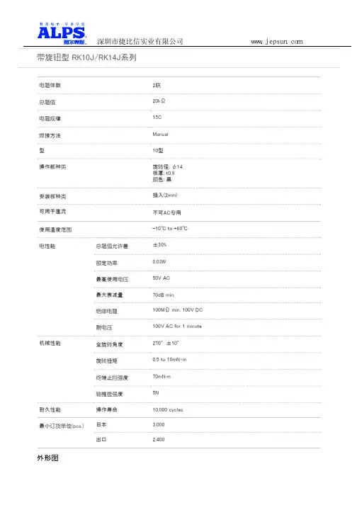
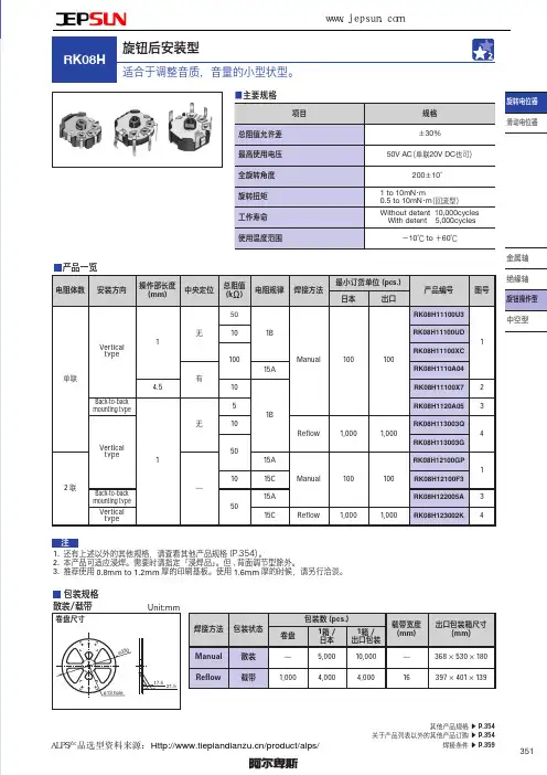
电阻体数2联总阻值20kΩ电阻规律15C 焊接方法Manual 型10型操作部种类旋转径: φ14板厚: t0.9颜色: 黑安装板种类插入(2mm)可用于直流不可AC 专用使用温度范围-10℃ to +60℃电性能总阻值允许差±30%额定功率0.03W 最高使用电压50V AC 最大衰减量70dB min.绝缘电阻100MΩ min. 100V DC 耐电压100V AC for 1 minute 机械性能全旋转角度270°±10°旋转扭矩0.5 to 10mN・m 终端止挡强度70mN·m 轴推拉强度5N 耐久性能操作寿命10,000 cycles 最小订货单位(pcs.)日本3,000出口2,400 外形图带旋钮型 RK10J/RK14J系列www.jepsun.com深圳市捷比信实业有限公司安装孔尺寸图自插入侧看端子排列www.jepsun.com深圳市捷比信实业有限公司电路图包装规格散装包装数(pcs.)1箱/日本3,0001箱/出口包装2,400出口包装箱尺寸(mm)371×250×190焊接条件手工焊接方式的参考举例烙铁头温度350℃ max.焊接时间3s max.焊接次数 1 time表示本系列共通的注释。
1. 本产品目录中产品的颜色,与实物的颜色有所差异。
2. 请以最小订购单位的N(整数)倍来订货。
3. 除了产品一览之外,还备有丰富的可适用产品规格。
4. RK14J,可用浸焊需要时请指定「浸焊品」。
50k a音量电位器分流电阻一、介绍50k a音量电位器的作用50k a音量电位器是一种用来控制电子设备音量的重要元件,它可以通过改变电阻值来调节电流,从而达到控制音量的目的。
在音响设备、电视机、汽车音响等电子产品中都有广泛的应用,是调节音量大小的关键部件之一。
二、50k a音量电位器的组成结构50k a音量电位器通常由电阻体、旋钮、引脚等部件组成。
其中,电阻体是影响电位器性能的重要部件,它能够改变电流的流动路径,从而实现对音量的调节。
三、50k a音量电位器的分流电阻原理分流电阻是指电流在电路中经过不同路径时,被分割成不同的部分,进而影响电路中的电流大小。
在50k a音量电位器中,分流电阻通过改变电阻体的位置,调整电路中的电流分布,实现调节音量的功能。
当旋钮转动时,电位器的电阻值会随之改变,从而改变电流的流动路径,进而影响音量大小。
四、对50k a音量电位器分流电阻的实验验证我们可以通过实验来验证50k a音量电位器的分流电阻原理。
具体步骤如下:1. 准备一个50k a音量电位器和一个电流表。
2. 将电流表与电路连接,并让电流通过电位器。
3. 转动电位器的旋钮,观察电流表的读数。
4. 不断调节旋钮,记录下不同电位器位置下电流表的读数。
5. 根据数据分析,验证分流电阻原理对音量的影响。
通过上述实验,我们可以得出结论:50k a音量电位器的分流电阻原理有效地影响了电流的大小,实现了对音量的调节。
五、50k a音量电位器在电子产品中的应用由于50k a音量电位器可以精确地控制音量大小,因此在各种电子产品中都有广泛的应用。
在音响设备中,50k a音量电位器可以通过旋钮轻松调节音量大小;在汽车音响中,也可以通过50k a音量电位器来实现音量的调节。
在今后的一定时间内,随着技术的不断发展,50k a音量电位器的应用领域还将继续扩大,其在电子产品中的作用也会变得更加重要。
六、结语通过以上内容我们可以了解到,50k a音量电位器是一种可以通过分流电阻原理来调节音量大小的电子元件。
TELEMARK880型晶控器用户手册(2003年6月7日首版发行)(未经通知,TELEMARK公司有权变更该手册中的任何内容)2003年版权AMPHENOL 是ALLIED公司的一个注册商标AMP 是TYCO/AMP股份有限公司的一个注册商标CONFLAT 是V ARIAN ASSOCIATE股份有限公司的一个注册商标IBM 是IMP公司的一个注册商标MICROSOFT 是MICROSOFT公司的一个注册商标MICRODOT 是MICRODOT股份有限公司的一个注册商标SWAGELOK 是CRAWFORD FITTING公司的一个注册商标WINDOWS 是MICROSOFT公司的一个注册商标1880型晶控器保证条款:兹保证:TELEMARK产品是由良好材料和工艺精制而成,符合规范规定要求,无任何加工弊端,质保期为12月。
TELEMARK从其它公司采购的元器件,其保质期不会低于这些公司向TELEMARK公司所作的保证期限,上述条款在按照TELEMARK公司所供说明书进行正确操作的情况下有效,但TELEMARK公司对安装和使用不当、误操作、人为事故、锈蚀不承担任何质保责任,在该质保期间,TELEMARK公司将免费进行维修,但运输费用将有用户承担,TELEMARK公司有权对最终质保条款内容进行调整。
用户责任:用户要按照该手册及其附加内容之说明对该设备的正确操作和适当保养负责,正确操作包括:按时更换磨损、破碎和所缺的零部件。
如果用户对装置的使用或安装有不理解的地方,应及时与TELEMARK公司联系。
用户按照本手册中“安装部分”之说明完成对装置的正确安装是极其重要的,若因装置安装不当而造成的损坏,本公司所承诺的质保条款将无效。
任何擅自对装置进行设计修改和功能变更都不属于本公司质保条款的质保范畴,一些后果均有用户承担。
安全警告:常规防范措施:任何人接触真空系统内或真空系统附近的高压电路都会造成致命伤,在打开真空室门或拆卸面板时一定要关闭电源,在连接晶控器之前,一定要使所有的高压馈入装置与一个接地钩短接。
TSS 半导体放电管产品选型指南T hyristor S urge S uppressors Selection Guide版权及最终解释权归君耀电子(BrightKing)所有V2,2018目录1TSS工作原理 (3)2TSS特点 (3)3TSS典型应用电路 (4)4TSS参数说明 (4)4.1.V DRM,I DRM (4)4.2.I H (5)4.3.V T,I T (6)4.4.V S,I S (6)4.5.V PP,I PP (6)5TSS选型注意事项 (7)5.1.反向截止电压(V DRM) (7)5.2.TSS的续流问题 (7)5.3.封装形式 (7)6TSS命名规则 (7)7君耀电子(BrightKing)TSS产品线 (8)1 TSS 工作原理TSS (Thyristor Surge Suppressors ),浪涌抑制晶闸管,也称半导体放电管,是采用半导体工艺制成的PNPN 结四层结构器件,其伏安特性(如图1)类似于晶闸管,具有典型的开关特性。
TSS 一般并联在电路中应用,正常工作状态下TSS 处于截止状态,当电路中由于感应雷、操作过电压等出现异常过电压时,TSS 快速导通泄放由异常过电压导致的异常过电流,保护后端设备免遭异常过电压的损坏,异常过电压消失后,TSS 又恢复至截止状态。
图2是TSS 第一象限放大图,TSS 的开关特性包含四个区域:断态区、击穿区、负电阻区和通态区。
断态区:是电压—电流特性的高电阻、低电流区。
该区域从原点延伸至击穿起始点。
断态电流是结反向电流和所有表面漏电流的综合,在该区可施加反向截止电压(V DRM )测量TSS 的漏电流(I DRM )。
击穿区:击穿区是电压—电流特性的低电阻、高电压区域。
该区域是从电压—电流特性的高动态电阻的低电流部分开始变化,至显著的低动态电阻区、电流剧增的区域。
最终当TSS 正反馈出现足以激活开通时,该区域终止。
负电阻区:负电阻区表示从击穿区开关点到通态状态的轨迹。
精密波形发生器总体描述:ICL8038的波形发生器是一个用最少的外部元件就能生产高精度正弦,方形,三角, 锯齿波和脉冲波形彻底单片集成电路。
频率(或重复频率)的选定从0.001hz到300khz可以选用电阻器或电容器来调节, 调频及扫描可以由同一个外部电压完成。
ICL8038精密函数发生器是采用肖特基势垒二极管等先进工艺制成的单片集成电路芯片,输出由温度和电源变化范围广而决定。
这个芯片和锁相回路作用, 具有在发生温度变化时产生低的频率漂移,最大不超过250ppm /℃特点:1、具有在发生温度变化时产生低的频率漂移,最大不超过50ppm/℃;2、正弦波输出具有低于1%的失真度;3、三角波输出具有0.1%高线性度;4、具有0.001Hz~1MHz的频率输出范围;工作变化周期宽;5、2%~98%之间任意可调;高的电平输出范围;6、从TTL电平至28V;7、具有正弦波、三角波和方波等多种函数信号输出;8、易于使用,只需要很少的外部条件。
封装引脚如下图:ICL8038内部原理框图最大限值范围:供电电压 (V— toV+)。
. . . . 。
. 。
. . 。
. 。
. . . 。
. . 。
. . . 。
. . . .36V输入电压 (任何管脚) . 。
. 。
. . 。
. . 。
v — v + 输入电流(管4—5)。
...。
..。
..。
.。
.。
...。
.。
.。
.。
.。
.。
...。
25mA输出槽电流(管脚3和9).。
..。
....。
..。
.。
.。
.。
.。
.。
.。
.。
.25mA工作条件温度范围ICL8038AC, ICL8038BC, ICL8038CC 。
. 。
. . 。
. .0℃ to 70℃图1:测试电路图2 ICL8038内部详细的示意图应用信息(看功能图)外接电容C由两个恒流源充电和放电,振荡电容C由外部接入,它是由内部两个恒流源来完成充电放电过程。
恒流源2的工作状态是由恒流源1对电容器C连续充电,增加电容电压,从而改变比较器的输入电平,比较器的状态改变,带动触发器翻转来连续控制的。
20型⾦属轴型 RK203系列电阻体数单联安装⽅向Vertical type軸受固定⽅法螺纹固定操作部形状平轴操作部长度30mm定位扭矩1⇔2 position: 40±202⇔18 position: 20±10位置数18旋转⾓度1⇔2 position: 25°2⇔18 position: 180°总阻值10kΩ电阻规律1B使⽤温度范围-40℃ to +85℃电性能总阻值允许差±20%额定功率0.05W最⾼使⽤电压50V AC, 30V DC绝缘电阻100MΩ min. 250V DC耐电压300V AC for 1 minute机械性能终端⽌挡强度0.5N·m轴推拉强度100N max.耐振性能10 to 55 to 10Hz/分, 全振幅1.5mm, X.Y.Z 3⽅向各2⼩时耐久性能操作寿命30,000 cycles最⼩订货单位(pcs.)⽇本400出⼝800外形图安装孔尺⼨图电路图附加零部件是附加到各产品上的零部件。
包装规格托盘包装数(pcs.)1箱/⽇本4001箱/出⼝包装800出⼝包装箱尺⼨(mm)374×508×272焊接条件浸焊⽅式的参考举例预热焊接⾯表⾯温度100℃ max.加热时间 2 min. max.浸焊焊接温度260±5℃ max.焊接时间5±1s焊接次数 2 time max.⼿⼯焊接⽅式的参考举例烙铁头温度300℃ max.焊接时间3s max.焊接次数 1 time表⽰本系列共通的注释。
1. 本产品⽬录中产品的颜⾊,与实物的颜⾊有所差异。
2. 该产品适⽤个别规格。
您希望订购时请在咨询时提供详细规格。
3. 请以最⼩订购单位的N(整数)倍来订货。
4. 本系列产品也可以⽤于车载。
的使⽤温度范围设定虽然⽐通常的⼤,但是请在使⽤时仔细确认正式的技术规格书。
电阻体数
单联安装方向
Vertical type 操作部长度
1mm 中央定位
无总阻值
50kΩ电阻规律
1B 焊接方法
Reflow 使用温度范围
-10℃ to +60℃电性能总阻值允许差
±30%额定功率
0.03W 最高使用电压
50V AC, 20V DC 最大衰减量
80dB min.剩余电阻
50Ω or less 机械性能全旋转角度
200°±10°旋转扭矩
0.5 to 10mN・m 终端止挡强度
0.1N·m 轴推拉强度
10N 耐久性能
操作寿命10,000 cycles 最小订货单位(pcs.)日本
4,000出口
4,000
外形图
旋钮后安装型 RK08H系列
www.jepsun.cn
深圳市捷比信实业有限公司
安装孔/端子排列图
1. DUMMY 端子,请在电路上以开放状态使用。
2. 斜线部表示的是焊锡部
电路图
包装规格
载带
梱包数(pcs.)1卷1,000
1箱/日本4,000
1箱/出口包装4,000
载带宽度(mm)16
出口包装箱尺寸(mm)401×397×139
焊接条件
回流方式的参考举例
1. 加热方式
为温风加热方式。
2. 温度测量方式
使用φ0.1~φ0.2的CA(K)或CC(T)进行测量,在焊接的连接部位置(铜箔面)测量,固定方式使用耐热胶带。
3. 温度分布
A B C D E F G H 回流焊
次数250℃200℃150℃150℃ 2 min.3s 40s 4 min.
2 time max.
1. 本产品, 在只有红外线的回流焊接炉中, 有焊接不附着的可能, 所以请使用温风回流焊接炉, 或红外线+ 温风回流焊接炉。
2. 上图所示温度是采用温风回流焊接方式时的电位器端子部的最高温度。
因为根据电路板的材质, 大小, 厚度等的不同, 电路板温度和电位器表面温度有相差很大的可能, 请注意, 电位器表面温度不要超过250℃。
3. 根据回流焊接槽的种类, 条件不同结果不同, 请事先充分进行确认之后使用。
表示本系列共通的注释。
1. 本产品目录中产品的颜色,与实物的颜色有所差异。
2. 请以最小订购单位的N(整数)倍来订货。
3. 除了产品一览之外,还备有丰富的可适用产品规格。
4. 本产品可适应浸焊。
需要时请指定「浸焊品」。
但,背面调节型除外。
5. 推荐使用0.8mm to 1.2mm厚的印刷基板。
使用1.6mm厚的时候,请另行洽谈。
www.jepsun.cn
深圳市捷比信实业有限公司。