约克YK离心冷水机组资料
- 格式:pdf
- 大小:5.87 MB
- 文档页数:132
培训内容1.常用的计量单位换算2.系统结构3.工作原理4.润滑系统4.常见故障5维护与保养计量单位换算长度1英寸=25.4mm 1米=100cm=3.94英寸(in) 容积1加仑(gallon)=4.55升(L)英制1加仑(gallon)=3.79升(L)美制质量1磅(Ib)=454克(g)1kg=2.2Ib流量1每加/仑每分(gpm)=3.786升/每分(L/m) 压力1磅(PSI)=6.89千帕(Kpa) 1Kpa=0.145PSI 温度℃=5(℉-32)/9 ℉=9/5+32热能1冷吨=3024Kcal=3.516KW功率1马力(Hp)=0.746千瓦特(Kw) 1kW=1.34HP常用术语:表压=绝对压力-大气压力真空度=大气压力-绝对压力蒸发器小温差=冷冻水出水温度-蒸发温度冷却器小温差=冷凝温度-冷却水出水温度小温差取决于换热器性能好坏过冷度=对应的饱和温度-离开冷凝器的制冷剂温度过热度=排气温度传-对应的冷凝饱和度油压差=油泵出口压力-压缩机的入口压力离心式冷水机组工作原理机组前视图机组后视图2010/4/14蒸发器冷凝器截流元件压缩机电机冷却塔制冷机组的整体布局机组代码YK机组结构离心机组的组成部件机组构造蒸发器冷凝器电动机齿轮叶轮预旋转导叶关键部件制冷设备的四个主要组成部分: 压缩机冷凝器节流(膨胀)装置蒸发器各部件的作用压缩机提升压力低压(低温)气体被吸入压缩机并被压缩成高压(高温)气体活塞式、双/ 单螺杆、回转式离心冷凝器从压缩机出来的高温制冷剂气体进入冷凝器,在一定压力下释放热量变成液体。
高温制冷剂在冷凝器中冷凝。
各部件的作用节流装置(膨胀阀) :液体经过节流装置使压力下降。
孔板、热力膨胀阀、电子膨胀阀、毛细管等蒸发器液体制冷剂进入蒸发器蒸发为气体。
制冷剂在蒸发器中吸收热量。
预旋转导流冷凝器过冷器均流板满液式蒸发器截流孔板叶片叶轮汽液分离板离心式冷水机组满液式蒸发器干式蒸发器满液式蒸发器压缩机吸气管均气板支撑板固定棒视镜支撑板液位控制油收集器回油管均液板液态冷媒供液管PEH蒸发器吸气口出水进水供液口离心式冷水机组汽液分离板离心式冷水机组预旋转导流叶片预旋转导叶部分开启关闭预旋转导流叶片全开预旋转导流叶片全关预旋转导流叶片预旋转导流叶片部分关闭离心式冷水机组叶轮叶轮离心式冷水机组均流板离心式冷水机组冷凝器高效换热铜管铜管规格加强部分常规部分230.025"0.050 - 0.053"220.028"0.053 - 0.056"200.035"0.059 - 0.063"实际铜管厚度水流管板铜管支撑板高效换热铜管高效换热铜管换热器采用新型高效换热型面(内螺纹/外肋片)提高机组效率,降低结垢率,节省维护费用水流方向筒体端板中间支撑板TubeSheetTube Support WATERFLOW离心式冷水机组过冷器离心式冷水机组截流孔板截流元件固定截流孔板可变截流孔板强化非设计工况性能液体管线调节阀制冷剂液位探头维持冷凝器最佳液位 通过MicroPanel控制叶轮预旋转导叶高速齿轮轴封止推轴承轴颈轴承轴颈轴承轴颈轴承连轴器低速齿轮高速齿轮低速齿轮特点及优势最优化的叶轮设计适应于各类特定的运行工况可靠相同部件在军事工业上使用单螺旋设计与VSD 完美配合轴与轴封剖面图YK系列轴封双层密封泰福龙C型密封环约克双层轴封的优点约克机组采用双层密封以保证轴承的润滑及密封; 冷媒进入压缩机前,已与润滑油彻底分离;冷媒在轴封处的泄漏微乎其微;喘振发生离心式压缩机旋转失速和喘振的差别旋转失速旋转失速是所有离心式压缩机在流量减小(负荷减小)和/或者压头增加(温度头增加)时发生的一种空气动力学中的扰动现象。
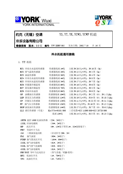
约克(无锡)空调YS,YT,YK,YCWS,YCWP机组冷冻设备有限公司维修指南版本:0.0版编号:YW-SERV-005 发布日期:2002-7-10 共16 页冷水机组通用接线1.YT 机组RT1 冷冻出水温度传感器传感器线束1#线主板J9-20红(+5V),J9-10黑(In)RT2 排气温度传感器传感器线束2#线主板J9-15红(+5V),J9-5黑(In)RT3 油温传感器传感器线束3#线主板J9-14红(+5V),J9-4黑(In)RT4 冷却出水温度传感器传感器线束4#线主板J9-18红(+5V),J9-8黑(In)RT5 冷却回水温度传感器传感器线束5#线主板J9-17红(+5V),J9-7黑(In)RT6 冷凝器冷媒温度传感器线束6#线主板J9-16红(+5V),J9-6黑(In)RT7 蒸发器冷媒温度传感器线束7#线主板J9-13红(+5V),J9-3黑(In)RT9 冷冻回水温度传感器线束9#线主板J9-19红(+5V),J9-9黑(In)OP 油槽油压传感器传感器线束10#线主板J9-11红(+5V),J9-2黑(0),J9-1白(In) LEP 蒸发压力传感器传感器线束11#线主板J8-19红(+5V),J8-9黑(0),J8-18白(In) CP 冷凝压力传感器传感器线束12#线主板J8-11红(+5V),J8-22黑(0),J8-21白(In) PP 抽气压力传感器传感器线束13#线主板J8-5红(+5V),J8-16黑(0),J8-15白(In) HOP油泵油压传感器传感器线束14#线主板J8-17红(+5V),J8-7黑(0),J8-6白(In)) LLS 液位传感器(可选)Kit 375w40101-000 三芯电缆+025-11890-000+025-28720-000线束15#线主板J8-14红(+5V),J8-3黑(0),J8-13白(In) 1HTR 温控1000瓦油加热器(23#、2#端子)1SOL 回油电磁阀(34#、2#端子)HP 高压开关(6#、15#端子常闭1#、32#故障端子)PRV 导流叶片马达1M 三相油泵起动柜(启动信号29#、2#)PM 抽气油泵(90#、2#端子)PTHP 抽气筒高压开关(164#、90#端子)2SOL 抽气油电磁阀(61#、2#端子)3SOL 抽气排气电磁阀(62#、2#端子)4SOL 抽气油电磁阀(61#、2#端子)PRV POT 导叶马达电位计(热气旁通,VSD使用)BFS 低油位开关(1#、70#端子)TFS 高油位开关(1#、71#端子)VMS 限位开关(1#、18#端子)2.YS机组RT1 冷冻出水温度传感器传感器线束1#线主板J9-20红(+5V),J9-10黑(In)RT2 排气温度传感器传感器线束2#线主板J9-15红(+5V),J9-5黑(In)RT3 油温传感器传感器线束3#线主板J9-14红(+5V),J9-4黑(In)RT4 冷却出水温度传感器传感器线束4#线主板J9-18红(+5V),J9-8黑(In)RT5 冷却回水温度传感器传感器线束5#线主板J9-17红(+5V),J9-7黑(In)RT7 蒸发器冷媒温度传感器线束7#线主板J9-13红(+5V),J9-3黑(In)RT9 冷冻回水温度传感器线束9#线主板J9-19红(+5V),J9-9黑(In)FOP 油过滤器压力传感器传感器线束10#线主板J9-11红(+5V),J9-2黑(0),J9-1白(In) EP 蒸发压力传感器传感器线束11#线主板J8-19红(+5V),J8-9黑(0),J8-18白(In) CP 冷凝压力传感器传感器线束12#线主板J8-11红(+5V),J8-22黑(0),J8-21白(In) POT 滑阀电位计传感器线束13#线主板J8-12红(+5V),J8-2黑(0),J8-1白(In) OP 油压传感器传感器线束14#线主板J8-17红(+5V),J8-7黑(0),J8-6白(In)) SOP 轴封油压传感器传感器线束15#线主板J8-5红(+5V),J8-16黑(0),J8-15白(In)1SOL 油路电磁阀(62#、2#端子)2SOL 液相电磁阀(29#、2#端子)1HTR 温控500瓦油加热器(28#、2#端子温控开关64#、28#)SOLS 油位开关(1#、18#正常闭合)aSOL 滑阀卸载(58#、2#)bSOL 滑阀上载(4#、2#)HP 高压开关(6#、15#常闭,1#、30#故障)3.YK机组RT1 冷冻出水温度传感器传感器线束1#线主板J9-20红(+5V),J9-10黑(In)RT2 排气温度传感器传感器线束2#线主板J9-15红(+5V),J9-5黑(In)RT3 油温传感器传感器线束3#线主板J9-14红(+5V),J9-4黑(In)RT4 冷却出水温度传感器传感器线束4#线主板J9-18红(+5V),J9-8黑(In)RT5 冷却回水温度传感器传感器线束5#线主板J9-17红(+5V),J9-7黑(In)RT6 冷凝器冷媒温度传感器线束6#线主板J9-16红(+5V),J9-6黑(In)RT7 蒸发器冷媒温度传感器线束7#线主板J9-13红(+5V),J9-3黑(In)RT9 冷冻回水温度传感器线束9#线主板J9-19红(+5V),J9-9黑(In)OP 油槽油压传感器传感器线束10#线主板J9-11红(+5V),J9-2黑(0),J9-1白(In) LEP 蒸发压力传感器传感器线束11#线主板J8-19红(+5V),J8-9黑(0),J8-18白(In) CP 冷凝压力传感器传感器线束12#线主板J8-11红(+5V),J8-22黑(0),J8-21白(In) 近程式传感探头传感器线束13#线J8-12棕(+5V),J8-2黑(0),J8-15兰(In),红(+24V) HOP泵油压传感器传感器线束14#线主板J8-17红(+5V),J8-7黑(0),J8-6白(In)) LLS 液位传感器传感器线束15#线主板J8-14红(+5V),J8-3黑(0),J8-13白(In) 变频油泵驱动传感器线束19#线主板J20-1白(PWM),J20-2红(+12),J20-3黑(En)OV A POT节流孔板电位计传感器线束21#线主板J7-12红(+5V),J7-24黑(0),J7-23白(In)1HTR 温控3000瓦三相油加热器(温控端子34#、107#,接触器端子107#、2#)1SOL 回油电磁阀(61#、2#)HP 高压开关(正常6#、15#常闭,故障1#、32#)OV A 节流孔板执行器PRV 导流叶片马达关键部件功能及接线1.Control panel由主板、I/O板、电源、显示器、键盘及CM-2板(机电式启动用)或ACCB(自适应容量控制板,VSD用)组成。
约克水冷离心式冷水机组YK介绍1、进口化率问题。
答:约克的进口化率最高。
2、单级压缩的可靠性。
答:约克产品也有采用多级压缩的,最多的可达8级压缩,用于工业冷冻,对于民用空调系统工况,压力差很小,多级压缩带来的效果并不明显。
而且单级压缩由于运动部件较少,设计简洁高效,大大降低了机组的不稳定性及故障率,所以YORK在中央空调领域选择了单级压缩。
多级压缩需要较长较粗的悬臂梁,较长的悬臂梁因挠度大可靠性差,另外较粗的轴大大加大轴与轴承之间的相对转速,加大了轴与轴承间的磨损,不利于机组的长期运行。
多级压缩必须要求在压缩机之间加装中间节能器,否则效果会非常差。
节能器只是相对于多级压缩机加此装置而言,并不是真正意义上的节能。
3、在参观时,如果遇到YK MODEL“C”“D”机组时,怎样解释?答:YORK YK机组处于不断更新改型的阶段,最新的MODEL“E”型机组其外观更美观,机组性能更好。
4、向业主介绍时应特别注意提YORK的品牌效应,闪光点、卖点。
答:微电脑控制中心、单级压缩、开式机组、低冷却水温。
5、开式和闭式的区别。
答:开式驱动:压缩机曲轴的功率输入端伸出机体之外,通过传动装置与原动机相连接。
在伸出部位要用轴封装置使轴段和机体间防止泄露,整个机器只要松开连接件后就可以拆开维修。
这种利用轴封装置的隔离作用,使原动机独立于制冷系统之外的驱动方式称为开式驱动。
半封闭驱动:电动机和压缩机连成一个整体,装在同一机体内,共用一根主轴,因而取消轴封装置,这样电动机便处于四周是制冷剂的环境中,被称为内置式电动机,也叫做封闭式(焊接)或半封闭式(螺栓连接)驱动方式。
开式、闭式比较:(1)首先因为闭式电机要将电机密封在壳体内,所以要求电机体积小,因此绕组的线径比开式的小,抗过载能力差,易造成电机的烧毁。
闭式机组由于采用冷剂冷却电机,如果制冷剂冷却不足或电源电压波动较大时,容易烧毁电机。
(2)在机组调试过程中,闭式机组抽真空不可能全部将系统内的气体抽干净。
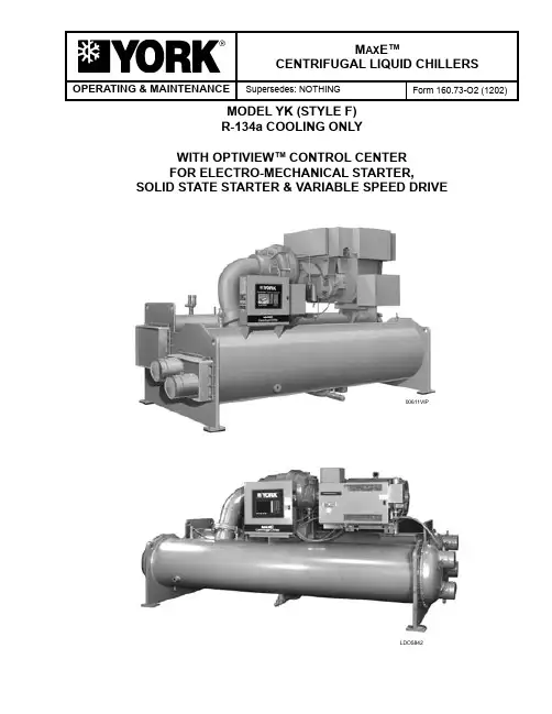
OPERATING & MAINTENANCEM AX E TMCENTRIFUGAL LIQUID CHILLERS Supersedes: NOTHING Form 160.73-O2 (1202)MODEL YK (STYLE F)R-134a COOLING ONLYWITH OPTIVIEW TM CONTROL CENTERFOR ELECTRO-MECHANICAL STARTER, SOLID STATE STARTER & VARIABLE SPEED DRIVE00611VIPLDO5842YORK INTERNATIONALFORM 160.73-O2(1202)2This equipment is a relatively complicated apparatus. During installation, operation, maintenance or service, individuals may be exposed to certain components or conditions including, but not limited to: refrigerants, oils, materials under pressure, rotating components, and both high and low voltage. Each of these items has the potential, if misused or handled improperly, to cause bodily injury or death. It is the obligation and respon-sibility of operating/service personnel to identify and recognize these inherent hazards, protect themselves, and proceed safely in completing their tasks. Failure to comply with any of these requirements could result in serious damage to the equipment and the propertyIMPORTANT!READ BEFORE PROCEEDING!GENERAL SAFETY GUIDELINESin which it is situated, as well as severe personal in-jury or death to themselves and people at the site.This document is intended for use by owner-authorized operating/service personnel. It is expected that this in-dividual possesses independent training that will enable them to perform their assigned tasks properly and safely. It is essential that, prior to performing any task on this equipment, this individual shall have read and under-stood this document and any referenced materials. This individual shall also be familiar with and comply with all applicable governmental standards and regulations pertaining to the task in question.SAFETY SYMBOLSThe following symbols are used in this document to alert the reader to areas of potential hazard:WARNING indicates a potentially hazardous situation which, if not avoided, could result in death or se-rious injury.DANGER indicates an imminently hazardous situation which, if not avoided, will result in death or serious injury.CAUTION identifies a hazard which could lead to damage to the machine, damage to other equipment and/or environmental pollution. Usually an instruction will be given, together with a brief explanation.External wiring, unless specified as an optional connection in the manufacturer’s product line, is NOT to be connected inside the micro panel cabinet. Devices such as relays, switches, transducers and controls may NOT be installed inside the micro panel. NO external wiring is allowed to be run through the micro panel. All wiring must be in accordance with YORK’s published specifications and must be performed ONLY by qualified YORK personnel. YORK will not be responsible for damages/problems resulting from improper connections to the controls or application of improper control signals. Failure to follow this will void the manufacturer’s warranty and cause serious damage to property or injury to persons.NOTE is used to highlight additional information which may be helpful to you.FORM 160.73-O2(1202)YORK INTERNATIONAL3CHANGEABILITY OF THIS DOCUMENTIt is the responsibility of operating/service personnel as to the applicability of these documents to the equip-ment in question. If there is any question in the mind of operating/service personnel as to the applicability of these documents, then, prior to working on the equipment, they should verify with the owner whether the equipment has been modified and if current literature is available.DESIGN LEVEL (F)POWER SUPPLY – for 60 Hz 5 for 50 Hz COMPRESSOR CODE H4, H5, H6, H7, H8, J1, J2, J3, J4, P1, P2, P3, P4, P5, P6, P7 CONDENSER CODEAB, AC, AD, BB, BC, BD, CF, CG, CH, DF, DG, DH, EB, EC, ED, FA, FB, FC, FD, GB, GC, GD, HB, HC, HD, JB, JC, JD, TB, TC, TD, VB, VC, VD EVAPORATOR CODEAB, AC, AD, BB, BC, BD, CF, CG, CH, DF, DG, DH MODEL EB, FB, FC, FD, GB, GC, GD, GF, GH, HB, HC, HF, HH, JF, JG, JH, TF, TG, TH, VF, VH, WF, WHNOMENCLATUREYK CB CB P6 – CM FMOTOR CODE 60 Hz 50 Hz CH CX 5CE 5CT CJ CY 5CF 5CU CK CZ 5CG 5CV CL CA 5CH 5CW CM CB 5CI 5CX CN DA 5CJ 5DA CP DB 5CK 5DB CR DC 5CL 5DC CS DD 5CM 5DD CT DE 5CN 5DE CU DF 5CO 5DF CV DH 5CP 5DG CW DJ 5CQ 5DH CF CG 5CR 5OJ 5CSIn complying with YORK’s policy for continuous prod-uct improvement, the information contained in this doc-ument is subject to change without notice. While YORK makes no commitment to update or provide current information automatically to the manual owner, that in-formation, if applicable, can be obtained by contacting the nearest YORK Applied Systems Service office.REFERENCE INSTRUCTIONSDESCRIPTION FORM NO. SOLID STATE STARTER (MOD “B”) – OPERATION & MAINTENANCE 160.00-O2 VARIABLE SPEED DRIVE – OPERATION 160.00-O1 VARIABLE SPEED DRIVE – SERVICE INSTRUCTIONS 160.00-M1 INSTALLATION 160.73-N1 OPTIVIEW CONTROL CENTER - SERVICE INSTRUCTIONS 160-54-M1 WIRING DIAGRAM – UNIT WITH ELECTRO-MECHANICAL STARTER 160.73-PW1 WIRING DIAGRAM – UNIT WITH MOD “A” SOLID STATE STARTER 160.73-PW2 WIRING DIAGRAM – UNIT WITH VARIABLE SPEED DRIVE 160.73-PW3 RENEWAL PARTS – UNIT 160.73-RP4 RENEWAL PARTS – OPTIVIEW CONTROL CENTER 160.54-RP1 OPTIVIEW™ PANEL - OPERATION & MAINTENANCE 160.54.O1FORM 160.73-O2(1202)4SECTION 1 Description of System and Fundamentals of Operation (6)System Operating Procedures......................................................................9System Components Description (1)5Operational Maintenance (21)Troubleshooting (23)SECTION 6Maintenance (25)SECTION 7Preventive Maintenance (34)TABLE OF CONTENTSYORK INTERNATIONALFORM 160.73-O2(1202)LIST OF FIGURESFIG. 1 – MODEL YK MAXE TM CHILLER (6)DETAIL A – COMPRESSOR PREROTATIONVANES (7)FIG. 2 – REFRIGERANT FLOW-THROUGH CHILLER (8)FIG. 3 – OIL LEVEL INDICATOR LABEL (9)FIG. 4 – CHILLER STARTING SEQUENCE &SHUTDOWN SEQUENCE(EM STARTER & SOLID STATE STARTER) (10)FIG. 5 – CHILLER STARTING SEQUENCE &SHUTDOWN SEQUENCE(VARIABLE SPEED DRIVE) (11)FIG. 6 – LIQUID CHILLER LOG SHEETS (12)FIG. 7 – SYSTEM COMPONENTS (15)FIG. 8 – SCHEMATIC DRAWING (YK) COMPRESSORLUBRICATION SYSTEM (16)FIG. 9 – OIL RETURN SYSTEM (21)FIG. 10 – CHARGING OIL RESERVOIR WITH OIL (22)FIG. 11– EVACUATION OF CHILLER (25)FIG. 12 – SATURATION CURVE (27)FIG. 13 – DIAGRAM - MEGGING MOTOR WINDINGS (29)FIG. 14 – MOTOR STATOR TEMPERATURE &INSULATION RESISTANCE (30)YORK INTERNATIONAL5FORM 160.73-O2(1202)6electro-mechanical starter, YORK Solid State Starter(optional), or Variable Speed Drive (optional).In operation, a liquid (water or brine to be chilled)flows through the evaporator, where boiling refrigerantabsorbs heat from the liquid. The chilled liquid is thenpiped to fan coil units or other air conditioning terminalunits, where it flows through finned coils, absorbing heatfrom the air. The warmed liquid is then returned to thechiller to complete the chilled liquid circuit.The refrigerant vapor, which is produced by the boil-ing action in the evaporator, flows to the compressorwhere the rotating impeller increases its pressure andtemperature and discharges it into the condenser. Waterflowing through the condenser tubes absorbs heat fromthe refrigerant vapor, causing it to condense. The con-denser water is supplied to the chiller from an externalSECTION 1DESCRIPTION OF SYSTEM AND FUNDAMENTALS OF OPERATION00116vip CONDENSERCONTROLCENTERCOMPRESSORMOTOREVAPORATORFIG. 1 – MODEL YK MAXE TM CHILLERSYSTEM OPERATION DESCRIPTION (SEE FIG. 2)The YORK Model YK MaxE TM Chiller is commonly ap-plied to large air conditioning systems, but may be used onother applications. The chiller consists of an open motormounted to a compressor (with integral speed increasinggears), condenser, evaporator and variable flow control.The chiller is controlled by a modern state of the art Mi-crocomputer Control Center that monitors its operation.The Control Center is programmed by the operator to suitjob specifications. Automatic timed start-ups and shut-downs are also programmable to suit nighttime, week-ends, and holidays. The operating status, temperatures,pressures, and other information pertinent to operationof the chiller are automatically displayed and read on agraphic display. Other displays can be observed by press-ing the keys as labeled on the Control Center. The chillerwith the OptiView Control Center is compatible with anYORK INTERNATIONALFORM 160.73-O2(1202)YORK INTERNATIONAL71source, usually a cooling tower. The condensed refrig-erant drains from the condenser into the liquid return line, where the variable orifice meters the flow of liquid refrigerant to the evaporator to complete the refrigerant circuit.7619A(D)DETAIL A –COMPRESSOR PREROTATION VANESThe major components of a chiller are selected to handle the refrigerant, which would be evaporated at full load design conditions. However, most systems will be called upon to deliver full load capacity for only a relatively small part of the time the unit is in operation.CAPACITY CONTROLThe major components of a chiller are selected for full load capacities, therefore capacity must be controlled to maintain a constant chilled liquid temperature leaving the evaporator. Prerotation vanes (PRV), located at the entrance to the compressor impeller, compensate for variation in load (See Detail A).The position of these vanes is automatically controlled through a lever arm attached to an electric motor located outside the compressor housing. The automatic adjust-ment of the vane position in effect provides the perfor-mance of many different compressors to match various load conditions from full load with vanes wide open to minimum load with vanes completely closed.YORK INTERNATIONALFORM 160.73-O2(1202)8FIG. 2 – REFRIGERANT FLOW-THRU CHILLER PREROTATION VANES (See Detail A)SUCTIONEVAPORATORELIMINATOROIL COOLERLD00924FLOW CONTROL ORIFICESUB-COOLERCONDENSERDISCHARGE BAFFLEDISCHARGECOMPRESSORFORM 160.73-O2(1202)YORK INTERNATIONAL9START-UP PROCEDUREPre-StartingPrior to starting the chiller, observe the OptiView Control Center. Make sure the display reads SYSTEM READY TO START .To pre-start the chiller, use the following procedure: 1.Oil Heater – The oil heater must be energized for 12 hours prior to starting the chiller.2.Prior to start, the clock must be programmed for the proper day and time. Any setpoints which are desired to be changed may be programmed. All Control Cen-ter setpoints should be programmed before the chiller is started. (Refer to Form 160.54-O1).Vent any air from the chiller water boxes prior to starting the water pumps. Failure to do so will result in pass baffle damage.START-UP1.If the chilled water pump is manually operated, start the pump. The Control Center will not allow the chiller to start unless chilled liquid flow is established through the unit. (A field supplied chilled water flow switch is required.) If the chilled liquid pump is wired to the Microcomputer Control Center the pump will automatically start, therefore, this step is not neces-sary.SECTION 2SYSTEM OPERATING PROCEDURESOIL HEATERSIf the oil heater is de-energized during a shutdown period, it must be energized for 12 hours prior to starting com-pressor, or remove all oil and recharge compressor with new oil. (See “Oil Charging Procedure”, page 22.)OIL HEATER OPERATIONThe oil heater operation is controlled by the OptiView™ Control Center. The heater is turned on and off to main-tain the oil temperature to a value 50°F (10°C) above the condenser saturation temperature. This is the target value and if the oil temperature falls to 4°F (-15.5°C) or more below the target, the heater is turned on. It is turned off when the oil temperature increases to 3°F (-16°C) above the target value.If the target value is greater than 160°F (71°C), the target defaults to 160°F (71°C). If the target value is less than 110°F (43.3°C), it defaults to 110°F (43.3°C). To prevent overheating of the oil in the event of a con-trol center component failure, the oil heater thermostat (1HTR) is set to open at 180°F (82°C).CHECKING THE OIL LEVEL IN THE OIL RESERVOIRProper operating oil level – During operation, the oil level should fall to the “Operating Range” identified on the vertical oil level indicator label. See Figure 3.• If the oil level during operation is in the “OverFull” region of the oil level indicator, oil should be removed from the oil reservoir, This reduces the oil level to the “Operating Range”.• If the oil level during operation is in the “Low Oil”region of the oil level indicator, oil should be added to the oil reservoir. (See “Oil Charging Procedure”, page 22)Comply with EPA and Local regu-lations when removing or disposingof Refrigeration System oil!FIG. 3 – OIL LEVEL INDICATOR LABELLD08647YORK INTERNATIONALFORM 160.73-O2(1202)102.To start the chiller, press the COMPRESSOR START switch. This switch will automatically spring return to the RUN position. (If the unit was previously started, press the STOP/RESET side of the COMPRESSOR switch and then press the START side of the switch to start the chiller.) When the start switch is energized, the Control Center is placed in an operating mode and any malfunction will be noted by messages on a graphic display.Any malfunctions which occur during STOP/RESET are also displayed.When the chiller is shut down, the prerotation vanes will close automatically to prevent loading the compressor on start-up.When the chiller starts to operate, the following au-tomatic sequences are initiated: (Refer to Fig. 4 & 5, “Chiller Starting & Shutdown Sequence Chart”.)1.The OptiView Control Center display message willread SYSTEM PRELUBE for the first 50 seconds of the starting sequence.2.The oil pump will start to circulate oil for a 50 second pre-run to establish oil flow and adequate lubrication to all bearings, gears, and rotating surfaces within the compressor.The high and low oil pressure transducers (OP) and the oil temperature sensor (RT3) will sense any mal-function in the lubrication system.3.The anti-recycle timer software function will operate after the 50 seconds of pre-run time. At this time, the timer will be initiated and will run for 30 minutes after the compressor starts. If the chiller shuts down during this period of time, it cannot be started until the timer completes the 30 minute cycle.4.The chilled liquid pump contacts will close, start-ing the chilled liquid pump, to allow liquid flow through the evaporator when the COMPRESSOR start switch is energized.5.After the first 50 seconds of operation, the com-pressor will start.6.For display messages and information pertaining to the operation of the OptiView™ Control Center, refer to Form 160.54-O1.FIG. 4 – CHILLER STARTING SEQUENCE & SHUTDOWN SEQUENCE (EM STARTER & SOLID STATE STARTER)LD04040** NOT FOR ALL SHUTDOWNS. REFER TO “DISPLAY MES-SAGES” SECTION OF THIS MANUAL.FORM 160.73-O2(1202)2FIG. 5 – CHILLER STARTING SEQUENCE & SHUTDOWN SEQUENCE (VARIABLE SPEED DRIVE)LD04130CHILLER OPERATIONAfter the compressor reaches its operating speed, the Prerotation Vanes will begin to open under the control of the Microprocessor Board which senses the leaving chilled liquid temperature. The unit capacity will vary to maintain the leaving CHILLED LIQUID TEMPERA-TURE setpoint. The Prerotation Vanes are modulated by an actuator under the control of the Microprocessor Board. The vane control routine employs proportional plus derivative (rate) control action. A drop in chilled liquid temperature will cause the actuator to close the Prerotation Vanes to decrease chiller capacity. When the chilled liquid temperature rises, the actuator will open the Prerotation Vanes to increase the capacity of the chiller.However, the current draw (amperes) by the compressor motor cannot exceed the setting of the % CURRENT LIMIT at any time during the unit operation, since the Microcomputer Control Center 40 to 100% three-phase peak current limit software function, plus the 3-phase 100% solid state overload current limiter (CM-2), on Electro-Mechanical Starter applications, or the Solid State Starter current Limit function will override the temperature control function and prevent the Prerotation Vanes from opening beyond the % CURRENT LIMIT setting.** NOT FOR ALL SHUTDOWNS. REFER TO “DISPLAY MES-SAGES” SECTION OF THIS MANUAL.If the load continues to decrease, after the Prerotation Vanes are entirely closed, the chiller will be shut down by the Leaving Chilled Liquid – Low Temperature Control.CONDENSER WATER TEMPERATURE CONTROLThe YORK MaxE TM chiller is designed to use less power by taking advantage of lower than design temperatures that are naturally produced by cooling towers throughout the operating year. Exact control of condenser water such as a cooling tower bypass, is not necessary for most installations. The chiller requires only that the minimum condenser water temperature be no lower than the valuedetermined by referring to the formula below:where:ECWT = Entering Condensing Water Temperature LCWT = Leaving Chilled Water TemperatureC Range = Condensing water temperature range at the given load condition.Min. ECWT = LCWT – C RANGE + 17ºF Min. ECWT = LCWT – C RANGE + 9.4ºCFORM 160.73-O2(1202)OPERATING INSPECTIONS – See Section 2By following a regular inspection using the display readings of the Microcomputer Control Center, and maintenance procedure, the operator will avoid serious operating difficulty. The following list of inspections and procedures should be used as a guide.Daily1.Check OptiView™ Control Center displays.2.If the compressor is in operation, check the bearing oil pressure on the SYSTEM Screen. Also check the oil level in the oil reservoir. Operating oil level should be between the upper and lower sight glasses. Drain or add oil if necessary.3.Check entering and leaving condenser water pressure and temperatures for comparison with job design conditions. Condenser water temperatures can be checked on the SYSTEM Screen.4.Check the entering and leaving chilled liquid tem-peratures and evaporator pressure for comparison with job design conditions on the SYSTEM Screen.5.Check the condenser saturation temperature (based upon condenser pressure sensed by the condenser transducer) on the SYSTEM Screen.6.Check the compressor discharge temperature on the SYSTEM Screen. During normal operation discharge temperature should not exceed 220°F (104°C).At start-up, the entering condenser water temperature may be as much as 25°F (14°C) colder than the standby return chilled water temperature. Cooling tower fan cycling will normally provide adequate control of the entering condenser water temperature on most instal-lations.OPERATING LOG SHEETA permanent daily record of system operating conditions (temperatures and pressures) recorded at regular inter-vals throughout each 24 hour operating period should be kept.An optional status printer is available for this purpose or Fig. 6 shows a log sheet used by YORK Personnel for recording test data on chiller systems. It is available from the factory in pads of 50 sheets each under Form 160.44-F7 and may be obtained through the nearest YORK office. Automatic data logging is possible by connecting the optional printer and programming the DATA LOGGER function.An accurate record of readings serves as a valuable reference for operating the system. Readings taken when a system is newly installed will establish normal conditions with which to compare later readings.For example, an increase in condenser approach temperature (condenser temperature minus leaving condenser water temperature) may be an indication of dirty condenser tubes.FIG. 6 – LIQUID CHILLER LOG SHEETS *NOTE: These items can be printed by an electronic printer connected to the Microboard and pressing the PRINTkey on the Keypad, or automatically using the Data Logger feature.LD0046723889AFORM 160.73-O2(1202)27.Check the compressor motor current on the SYSTEM Screen.8.Check for any signs of dirty or fouled condenser tubes. (The temperature difference between water leaving condenser and saturated condensing tem-perature should not exceed the difference recorded for a new unit by more than 4°F, 2.2°C).Weekly1.Check the refrigerant charge. (See “Checking The Refrigerant Charge”, page 28.)2.Leak check the entire chiller.Quarterly1.Perform chemical analysis of oil.Semi-Annually (or more often as required) 1.Change and inspect compressor oil filter element.2.Oil return system. a.Change dehydrator.b.Check nozzle of eductor for foreign particles. 3.Check controls and safety cutouts.Annually (more often if necessary)If quarterly inspection indicates oil is fine, replacing the oil is not necessary.1.Drain and replace the oil in the compressor oil sump. (See “Oil Charging Procedure” page 22.) 2.Evaporator and Condenser. a.Inspect and clean water strainers. b.Inspect and clean tubes as required. c.Inspect end sheets.pressor Drive Motor (See motor manufacturers maintenance and service instruction supplied with unit) a.Clean air passages and windings per manufac-turers instructions.b.Meg motor windings – See Fig. 13 for details.c.Lubricate per motor manufacturer recommenda-tions.4.Inspect and service electrical components as necessary.5.Perform refrigerant analysis.NEED FOR MAINTENANCE OR SERVICEIf the system is malfunctioning in any manner or the unit is stopped by one of the safety controls, consult the “Operation Analysis Chart”, (Table 1), pages 23 and 24 of this instruction. After consulting this chart, if you are unable to make the proper repairs or adjust-ments to start the compressor or the particular trouble continues to hinder the performance of the unit, please call the nearest YORK District Office. Failure to report constant troubles could damage the unit and increase the cost of repairs.STOPPING THE SYSTEMThe Optiview™ Control Center can be programmed to start and stop automatically (maximum, once each day) whenever desired. Refer to Form 160.54-O1. To stop the chiller, proceed as follows:1.Push the COMPRESSOR STOP/RESET switch. The compressor will stop automatically. The oil pump will continue to run for coastdown period. The oil pump will then stop automatically.2.Stop the chilled water pump (if not wired into the Microcomputer Control Center, in which case it will shut off automatically simultaneously with the oil pump.) (The actual water pump contact operation is dependent upon the position of Microboard jumper J54.)3.Open the switch to the cooling tower fan motors, if used.4.The compressor sump oil heater is energized when the unit is stopped.PROLONGED SHUTDOWNIf the chiller is to be shut down for an extended period of time (for example, over the winter season), the following paragraphs outline the procedure to be followed.1.Test all system joints for refrigerant leaks with aFORM 160.73-O2(1202)leak detector. If any leaks are found, they should be repaired before allowing the system to stand for a long period of time.During long idle periods, the tightness of the system should be checked periodically.2.If freezing temperatures are encountered while thesystem is idle, carefully drain the cooling water from the cooling tower, condenser, condenser pump, and the chilled water system-chilled water pump and coils.Open the drains on the evaporator and condenser liquid heads to assure complete drainage. (If a Vari-able Speed Drive, drain its water cooling system. If Solid State Starter. drain water from starter cooling loop.)3.On the SETUP Screen, disable the clock. This con-serves the battery.4.Open the main disconnect switches to the compressormotor, condenser water pump and the chilled water pump. Open the 115 volt circuit to the Control Cen-ter.FORM 160.73-O2(1202)SECTION 3SYSTEM COMPONENTS DESCRIPTIONMOTOREVAPORATORCOMPRESSORSUCTIONDUAL RELIEF VALVESSIGHT GLASSVARIABLE SPEEDOIL PUMP CONTROLBOX REFRIGERANT CHARGING VALVE00611vipFRONT VIEWFIG. 7 – SYSTEM COMPONENTSOPTIVIEW CONTROLCENTER3FORM 160.73-O2(1202)FIG. 7 – SYSTEM COMPONENTS (CONT’D)28778ADISCHARGE LINEOIL COOLEROIL RESERVOIRPUMPREAR VIEWFORM 160.73-O2(1202)GENERALThe YORK Model YK MaxE TM Centrifugal Liquid Chiller is completely factory-packaged including evapo-rator, condenser, compressor, motor, lubrication system, OptiView Control Center, and all interconnecting unit piping and wiring.COMPRESSORThe compressor is a single-stage centrifugal type pow-ered by an open-drive electric motor.The rotor assembly consists of a heat-treated alloy steel drive shaft and impeller shaft with a cast aluminum, fully shrouded impeller. The impeller is designed for bal-anced thrust and is dynamically balanced and over-speed tested. The inserted type journal and thrust bearings are fabricated of aluminum alloy. Single helical gears with crowned teeth are designed so that more than one tooth is in contact at all times. Gears are integrally assembled in the compressor rotor support and are film lubricated. Each gear is individually mounted in its own journal and thrust bearings.The open-drive compressor shaft seal is a double bellows cartridge style with ceramic internal and atmospheric seal faces. The seal is oil-flooded at all times and is pressure-lubricated during operation.CAPACITY CONTROLPrerotation vanes (PRV) modulate chiller capac-ity from 100% to as low as 15% of design for normal air conditioning applications. Operation is by an external, electric PRV actuator which automatically controls the vane position to main-tain a constant leaving chilled liquid temperature.COMPRESSOR LUBRICATION SYSTEM(See Fig. 8)The chiller lubrication system consists of the oil pump, oil filter, oil cooler and all interconnecting oil piping and passages. There are main points within the motor-compressor which must be supplied with forced lubri-cation as follows: pressor Drive Shaft (Low Speed)a.Shaft seal.b.Front and rear journal bearings – one on eachside of driving gear.c.Low speed thrust bearing (forward and reverse).pressor Driven Shaft (High Speed)a.Forward and reverse high speed thrustbearing.b.Two journal bearings.3.Speed Increasing Gearsa.Meshing surfaces of drive and pinion gear teeth.To provide the required amount of oil under the nec-essary pressure to properly lubricate these parts, a motor driven submersible oil pump is located in a remote oil sump.Upon pressing of the COMPRESSOR START switchon the Control Center, the oil pump is immediately energized. After a 50 second pre-lube period, the com-pressor motor will start. The oil pump will continue torun during the entire operation of the compressor, andfor 150 seconds during compressor coastdown.The submerged oil pump takes suction from the sur-rounding oil and discharges it to the oil cooler where heatis rejected. The oil flows from the oil cooler to the oil filter. The oil leaves the filter and flows to the emergencyoil reservoir where it is distributed to the compressor bearings. The oil lubricates the compressor rotating components and is returned to the oil sump.There is an emergency oil reservoir located at the highest point in the lubrication system internally inthe compressor. It provides an oil supply to the various bearings and gears in the event of a system shutdown due to power failure. The reservoir, located on the top ofthe compressor, allows the oil to be distributed throughthe passages by gravity flow, thus providing necessary lubrication during the compressor coastdown.3。
约克离心式冷水机组介绍
离心式压缩机是冷水机组的核心组件。
它通过压缩制冷剂气体使其升温并转变为高温高压蒸汽,然后将其传递给冷凝器。
冷凝器是用来转移制冷剂的热量的组件。
制冷剂在冷凝器中被冷却,从而使其变成液态。
冷却过程中,冷却水或空气用来吸收制冷剂的热量,然后将热量释放到环境中。
蒸发器是用来吸收热量的组件。
制冷剂从冷凝器中进入蒸发器,在蒸发器内通过换热的方式吸收室内空气的热量,从而使室内空气变得更加凉爽。
同时,制冷剂从液态变为气态。
冷却塔用来冷却冷却剂在蒸发器中释放的热量。
它以水或空气作为冷却介质,通过与蒸发器中的冷却剂接触,将热量转移到冷却介质中,从而降低冷却剂的温度。
控制系统是用来监控和调节冷水机组的运行的组件。
它可以根据室内温度和湿度,冷却需求等参数来自动控制冷水机组的运行状态,从而提高机组的效率和性能。
其次,约克离心式冷水机组具有灵活性。
它们可以适应不同的冷却需求,并可以根据实际情况进行调整。
它们可以根据需要提供冷水或者冷却能力,并且可以工作在不同的环境温度和湿度条件下。
此外,约克离心式冷水机组的运行成本相对较低。
它们具有较高的能效比,能够节约能源并降低能源消耗。
同时,由于其高效率和可靠性,减少了机组的维护成本和停机时间。
总结起来,约克离心式冷水机组是一种高效、可靠、灵活且节能的空调设备。
它们广泛应用于各种工业和商业建筑中,为室内提供舒适的温度和湿度。
通过不断的技术创新和优化,约克离心式冷水机组将继续发展和改进,以满足不断变化的市场需求。

约克离心式冷水机组说明书约克离心式冷水机组是一种高效节能的空调设备,它可以为各种建筑物、工厂、商场、办公室、会议室等提供冷水和热水服务。
本文将对约克离心式冷水机组的结构、工作原理、使用方法和维护保养等方面进行详细说明。
一、结构约克离心式冷水机组由压缩机、冷凝器、膨胀阀和蒸发器四部分组成。
其中,压缩机是机组的心脏,它将低温低压的制冷剂吸入,经过压缩、升温,使制冷剂成为高温高压气体,通常用双螺杆压缩机,具有高效节能特点。
冷凝器是用来除去制冷剂中的热量,将其变成液体,使其能够继续循环使用的重要部分。
膨胀阀是用来调节制冷剂流量的,它能够使制冷剂从高压变为低压,降低了其温度和压力,从而形成制冷效果。
蒸发器是用来吸收空气中的热量,使冷却剂变成蒸汽,从而实现空调降温的部分。
除此之外,约克离心式冷水机组还包括水泵、水箱、换热器、控制系统等配件。
其中,水泵将冷水循环送回冷水机组循环使用,水箱则储存冷水,换热器用来将热水或者冷水传递给需要的地方,控制系统则可以实现对机组的控制和监测。
二、工作原理约克离心式冷水机组是通过压缩机的工作,将低温低压的制冷剂吸入,经过压缩、升温,使制冷剂成为高温高压气体,然后通过冷凝器的作用,使制冷剂的温度降低,成为高压液体。
接着,通过膨胀阀的作用,使制冷剂从高压变为低压,降低了其温度和压力,在蒸发器中吸收空气中的热量,使冷却剂变成蒸汽,从而实现空调降温。
在整个过程中,水泵通过循环系统将冷水送回冷水机组进行循环使用,水箱储存着冷水,供应控制系统控制换热器的工作,同时控制系统可以对整个机组进行控制和监测。
三、使用方法在使用约克离心式冷水机组时,应当按照生产厂家的说明书来操作,保证机组的正常运行。
首先,要保证机组接通电源,水泵和空调系统正常运行;其次,可以通过控制系统对机组的工作状态进行监测和控制;最后,应当对机组进行定期的维护和保养,保证机组的正常运行,延长机组的使用寿命。
四、维护保养约克离心式冷水机组的维护保养包括机组的日常维护、周期性维护和定期检测等方面。
约克离心冷水机组参数1. 简介约克离心冷水机组是一种常用的制冷设备,广泛应用于工业、商业和住宅建筑中。
该设备通过离心压缩机将低温制冷剂压缩成高温、高压气体,然后通过冷凝器散热,使气体冷凝成液体。
最后,通过膨胀阀控制制冷剂的流量和压力,使其进入蒸发器进行蒸发,从而吸收热量并降低空气温度。
2. 参数说明约克离心冷水机组的参数主要包括以下几个方面:2.1 制冷量制冷量是指单位时间内从空气或其他物体中吸收的热量。
约克离心冷水机组的制冷量通常以千瓦(kW)为单位进行表示。
制冷量受到多个因素的影响,包括环境温度、湿度、风速等。
2.2 冷却容量约克离心冷水机组的冷却容量是指单位时间内从空气或其他物体中排出的热量。
冷却容量通常以千瓦(kW)为单位进行表示。
冷却容量的大小取决于制冷剂的种类、流量以及冷却器的设计。
2.3 COP(能效比)COP(Coefficient of Performance)是指冷水机组在特定工况下单位制冷量所消耗的能量与输入电能之比。
COP越高,表示单位能量消耗越低,性能越好。
2.4 压缩机类型约克离心冷水机组采用离心压缩机,该类型压缩机具有高效、低噪音、可靠性强等特点。
2.5 制冷剂种类约克离心冷水机组常用的制冷剂种类有R22、R134a等。
制冷剂的选择需要考虑其环保性、安全性和性能匹配等因素。
3. 应用领域约克离心冷水机组广泛应用于以下领域:3.1 工业制造在工业制造过程中,需要对设备或产品进行降温或恒温处理。
约克离心冷水机组可以提供稳定可靠的制冷和恒温功能,满足各种生产需求。
3.2 商业建筑商业建筑如办公楼、商场、酒店等需要大量的制冷设备来保持室内舒适温度。
约克离心冷水机组具有高效节能、运行稳定的特点,适用于商业建筑的中央空调系统。
3.3 医疗领域医疗设施对温度和湿度的控制要求非常严格,约克离心冷水机组可以提供精确的温湿度控制,确保医疗环境的洁净和安全。
3.4 住宅建筑在高层住宅、别墅等住宅建筑中,约克离心冷水机组可以提供整体的中央空调解决方案,满足不同户型和使用需求。

约克离心式冷水机组主要参数英文版York Centrifugal Chiller Main ParametersYork centrifugal chillers are widely used in various industries for their high efficiency and reliability. These chillers are designed to provide cooling for large buildings, industrial processes, and other applications where a constant supply of chilled water is required.The main parameters of York centrifugal chillers include cooling capacity, power consumption, refrigerant type, and operating conditions. The cooling capacity of a chiller is measured in tons or kilowatts, and it indicates the amount of heat that the chiller can remove from a space in a given period of time. The power consumption of a chiller is also an important parameter, as it determines the operating costs of the system.The refrigerant type used in York centrifugal chillers is typically R-134a or R-123, which are environmentally friendly and have low global warming potentials. These refrigerants are non-toxic and non-flammable, making them safe for use in various applications. The operating conditions of a chiller, such as ambient temperature and humidity, also play a crucial role in its performance and efficiency.In conclusion, York centrifugal chillers are an excellent choice for cooling large spaces and industrial processes. With their high efficiency, reliability, and environmentally friendly refrigerants, these chillers are a cost-effective solution for various cooling applications.中文翻译约克离心式冷水机组主要参数约克离心式冷水机组以其高效率和可靠性在各个行业广泛应用。
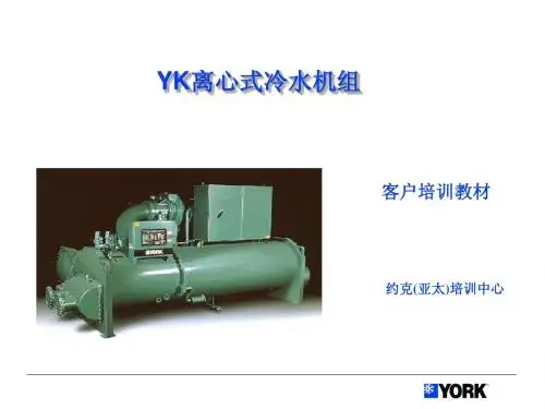
, 了解每个, 包括日常设备检3YK 离心式冷水机组设计特点约克OptiView TM YK 离心式冷水机组能提供各种形式的配置,以满足不同用户的需要。
配置约克变频驱动装置(VSD)的YK 机组彩色图象显示控制中心约克OptiView TM 彩色图象显示控制中心,同时显示机组每个部件的运行参数与插图,控制简单形象。
变频配置,高效节能(选项)配置变频驱动器,独特的自适应容量控制将电机变频和导流叶片调节完美地结合在一起,大大提高机组的效率,令部分负荷耗电指标低达0.2kW/ton ,机组的年节能可达15%-25%。
单级压缩机,先进可靠约克单级压缩机的运动部件较少、设计简洁高效,它的长工作寿命已在许多应用中得到了证明。
轻质、高强度的铝制叶轮采用后弯叶片,效率很高。
翼形导流叶片减少了气流的扰动,使部分负荷能保持最高效的性能。
压缩机可平稳地从100% 卸载到最低负荷。
开式电机,安全可靠闭式电机烧毁后会对冷水机组造成灾难性的破坏,整台机组必须彻底清洁,并要更换制冷剂后方可使用。
约克YK 离心式冷水机组采用风冷式电机,从而避免了这种危险。
制冷剂根本不会与电机接触,避免了对冷水机组其它部分的污染。
保险公司在对大型空调设备保险时,通常风冷式电机的保险费要比制冷剂冷却的闭式电机低得多。
充分利用低温冷却水,显著节能符合实际工况下的节能要求,机组能充分利用低达12.8℃的冷却水,获得明显的节能效果,而不像有些机组那样需要人为地将水温控制在21~24℃。
高效热交换器,表现卓越热交换器采用了最新的高效换热铜管,使传热效率最佳、结构紧凑。
水侧和制冷剂侧强化传热,减少机组能耗和管道结垢。
结构紧凑,安装方便机组设计精密紧凑,大大减少机房占地面积。
安装时只需少量的接管和布线,帮助用户节约安装费用。
环保冷媒,造福人类- 约克YK 冷水机组的性能经美国空调制冷供暖协会(AHRI)认证。
- 符合最新的AHRI550/590标准。
- 采用HFC-134a 环保制冷剂,对臭氧层没有损害。