SINAMICS V10 V20 V50 V60 V80基本说明
- 格式:doc
- 大小:738.50 KB
- 文档页数:10
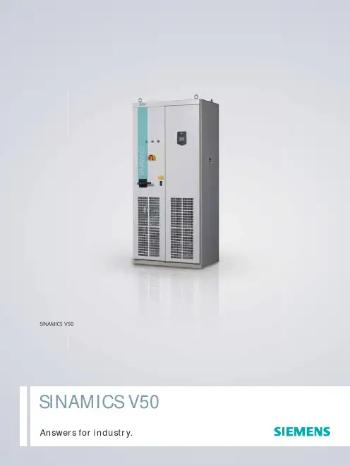
高品质单机传动变频调速柜全新设计节能首选SINAMICS V50 高品质单机传动变频调速柜是西门子公司新推出的又一款低压交流变频器,典型应用为风机和泵。
紧凑的柜体结构,高度模块化设计,成就了高品质的柜式装置,并通过了严格的整机测试,具有极高的性价比。
SINAMICS V50Answers for industry.应用SINAMICS V50 高品质单机传动变频调速柜适用于多种变转矩负载的单机传动应用,包括平方转矩、线性转矩及恒功率负载类型,典型应用如下:• 风机• 泵SINAMICS V50 高品质单机传动变频调速柜满足电力、水及污水处理、石油化工、水泥、矿山、冶金、船舶等行业标准,特别具有电力行业专用配置。
高品质柜式装置• 柜式装置-保证变频系统整体的高品质• 紧凑的柜体设计-节省占地面积达 30%• 采用高品质柜体• 柜内采用高品质低压元件• 柜内配置强电保护• 通过严格整机测试更多标准配置• 8MF 机柜• 标准保护等级 IP20• 操作面板 BOP 2• 电源输入端子• 电机输出端子• 进线主开关及快熔保险•输入电抗器• EMC(2 类工业环境)滤波器• 功率单元(集成整流,直流及逆变环节)• 冷却风扇• 主控板• RS485 接口• 模拟量/数字量输入输出端子接口板• 强电保护板输入电抗器主开关及快熔客户端子电源端子操作面板 BOP 2主控板箱功率单元(整流,直流,逆变,EMC 滤波器)风扇电机端子西门子公司版权所有如有变动,恕不事先通知订货号: E20001-A9620-C600-V1-5D00648-SH905695-020910质量SINAMICS V50 高品质单机传动变频调速柜的生产制造满足高质量标准的严格要求,要求具有最大的产品可靠性、可用性、功能性,经济效益程度极高。
产品的开发,设计,制造及订货处理和物流供应均通过 DIN ISO 9001 认证。
输入电压 3AC 输出功率380V~415V55kW~500kWSINAMICS V50 高品质单机传动变频调速柜节能效果显著,是定速电机实行变频改造,实现节能降耗的理想之选。
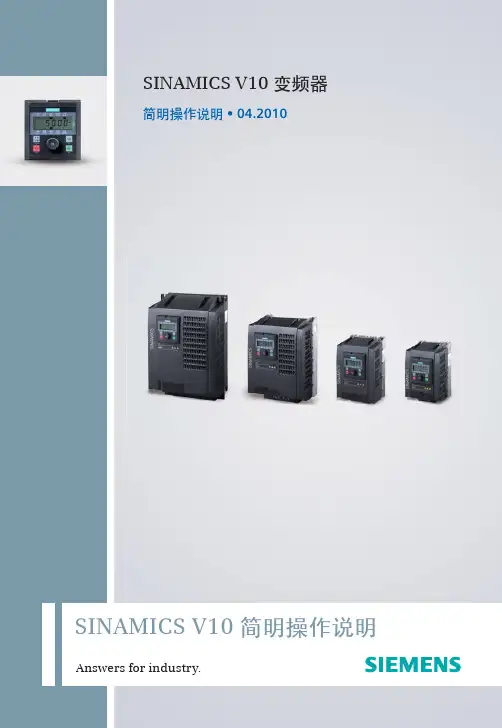
1Answers for industry.SINAMICS V10 简明操作说明SINAMICS V10 变频器简明操作说明 • 04.20102机械安装 (3)电气安装 (6)调试 (8)参数列表 (23)故障与报警 (27)技术规格 (29)其他参考信息 ..............................31SINAMICS V10 变频器简明操作说明 • 04.20103SINAMICS V10 变频器SINAMICS V10是一款多用途的经济型工业变频器,它具备了通用驱动的基本功能,可以用于控制三相交流鼠笼式异步电机。
SINAMICS V10有四种外形尺寸可供选择,其功率范围覆盖0.55kW 到22kW 。
警告本设备带有危险电压而且它所控制的是带有危险电压的转动机件。
如果不按照要求进行操作就可能会造成死亡、严重的人身伤害或重大的财产损失。
注意触电的危险。
即使电源已经切断,变频器的直流回路电容器上仍然带有危险电压,因此在电源关断5分钟以后才允许打开本设备。
如果设备正在运行,不得将设备上的端子块取下。
设备正常运行时可能会产生>3.5mA 的漏地电流。
因此,设备必须永久接地。
必须将设备垂直安装在电柜内。
如需了解更多的安全注意事项,参见《SINAMICS V10变频器操作说明》。
安全注意事项机械安装1.安装间距可以将几个变频器并排或者上下安装在一起,其安装间距要求如下:上下安装:变频器上部和下部都应留下至少100mm 的通风间隙。
并排安装:变频器左右两侧都应留下距离至少为“A”的通风间隙(见下图)。
!2.安装方式• 壁挂式安装- 壁挂式安装为默认安装方式;- 无需使用任何安装组件;- 整个变频器直接安装在电柜内。
• 穿墙式安装- 要求使用穿墙式安装组件。
- 变频器主体安装在电柜内,散热器延伸至电柜外。
- 适用于纺织等应用场合。
- 具体安装说明见SINAMICS V10穿墙式安装组件的《产品信息》或《SINAMICS V10变频器操作说明》。
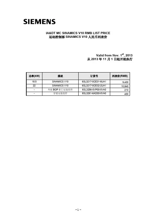
IA&DT MC SINAMICS V10 RMB LIST PRICE运动控制部SINAMICS V10人民币列表价Valid from Nov. 1st, 2013从2013年11月1日起开始执行功率(kW) 描述订货号列表价(RMB)V10 6SL3217-0CE31-8UA1 9,40018.5 SINAMICS22 SINAMICS6SL3217-0CE32-2UA1 10,840V10- 外接BOP柜门安装组件6SL3256-0VP00-0VA0 210 - 穿墙安装组件6SL3261-6AD00-0VA0 400IA&DT MC SINAMICS V60 RMB LIST PRICE运动控制部SINAMICS V60人民币列表价Valid from Nov. 1st, 2013从2013年11月1日起开始执行V60驱动器功率1FL5电机扭矩描述 V60 驱动包订货号列表价(RMB) 不带抱闸,光轴, 5m电缆线 6FC5548-0AF02-0AF0 7,482不带抱闸,光轴,10m电缆线 6FC5548-0AF02-0BA0 7,843带抱闸,光轴,5m电缆线6FC5548-0AF02-1AF0 9,235带抱闸,光轴,10m电缆线6FC5548-0AF02-1BA0 9,659不带抱闸,带键槽,5m电缆线A5E03623148 7,482不带抱闸,带键槽,10m电缆线A5E03623150 7,843带抱闸,带键槽,5m电缆线A5E03623152 9,235Pn= 0.8kW Nn=4Nm带抱闸,带键槽,10m电缆线A5E03623153 9,659不带抱闸,光轴, 5m电缆线6FC5548-0AF03-0AF0 7,896不带抱闸,光轴,10m电缆线6FC5548-0AF03-0BA0 8,257带抱闸,光轴,5m电缆线6FC5548-0AF03-1AF0 9,649带抱闸,光轴,10m电缆线6FC5548-0AF03-1BA0 10,073不带抱闸,带键槽,5m电缆线A5E03623154 7,896不带抱闸,带键槽,10m电缆线A5E03255846 8,257带抱闸,带键槽,5m电缆线A5E03623156 9,649 Pn=1.2kW Nn=6Nm带抱闸,带键槽,10m电缆线A5E03623155 10,073不带抱闸,光轴, 5m电缆线6FC5548-0AF04-0AF0 8,009不带抱闸,光轴,10m电缆线6FC5548-0AF04-0BA0 8,369带抱闸,光轴,5m电缆线6FC5548-0AF04-1AF0 9,762带抱闸,光轴,10m电缆线6FC5548-0AF04-1BA0 10,186不带抱闸,带键槽,5m电缆线A5E03623158 8,009不带抱闸,带键槽,10m电缆线A5E03255842 8,369带抱闸,带键槽,5m电缆线A5E03623160 9,762 Pn=1.6kW Nn=7.7Nm带抱闸,带键槽,10m电缆线A5E03623161 10,186不带抱闸,光轴, 5m电缆线6FC5548-0AF05-0AF0 8,929不带抱闸,光轴,10m电缆线6FC5548-0AF05-0BA0 9,290带抱闸,光轴,5m电缆线6FC5548-0AF05-1AF0 10,683带抱闸,光轴,10m电缆线6FC5548-0AF05-1BA0 11,106不带抱闸,带键槽,5m电缆线A5E03623162 8,929不带抱闸,带键槽,10m电缆线A5E03623163 9,290带抱闸,带键槽,5m电缆线A5E03623164 10,683 Pn=2.0kW Nn=10Nm带抱闸,带键槽,10m电缆线A5E03623165 11,106用于S7-200/S7-1200和V60连接的信号电缆线* 6ES7298-2DS23-0XA0 415备注:驱动包内电缆包含动力线、编码器线及抱闸线(如果配套抱闸电机)* 此信号电缆不包含在驱动包内,如有需要,请单独订购。
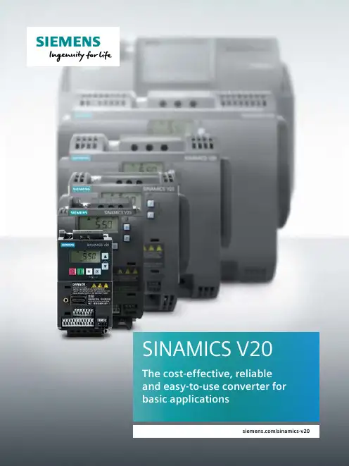
SINAMICS V20The cost-effective, reliable and easy-to-use converter for basic applications/sinamics-v202Power range 0.12 kW to 30 kW (1/6 hp to 40 hp)Voltage range 1AC 200 V ... 240 V (–10% / +10%)1), 2) 3AC 380 V ... 480 V (–15% / +10%)Control modesV/f V²/f FCC V/f multi-point1)Single-phase devices can also be connected to two phases of a 3-phase 120/240 V supply system. The voltage between L1 and L2 should be in the range of 200 V to 240 V, –10% to +10% (whether phase to phase or phase to neutral). You can find detailed information here:/cs/document/1094762602)V oltage tolerance for FSAA/FSAB (-15% / +10%)SINAMICS V20, the versatile converter for basic demandsToday, in an increasing number of applications in plant and machinery construction, individual automation and drive solutions are demanded that automate simple motion sequences with low associated requirements.With its compact SINAMICS V20, the basic performance converter, Siemens offers a simple and cost-effective drive solution for these types of applications. SINAMICS V20 sets itself apart with its quick commissioning times, ease of operation, robustness and cost efficiency.With seven frame sizes, it covers a power range extending from 0.12 kW up to 30 kW (1/6 hp up to 40 hp). Minimize your costsEngineering, commissioning and operating costs must be kept as low as possible. You have precisely the right solution with our SINAMICS V20. To increase energy efficiency, the converter is equipped with control tech-nology designed to achieve optimum energy efficiency through automatic flux reduction. Not only this, it displays the actual energy consumption and has additional, integ r ated energy-saving functions. This allows energy consumption to be slashed drastically.Typical applications3Easy to install4Easy to useEasy to save money6Integrated and innovative support7Complete motion control solutions from SiemensSINAMICS V20 and SIMATIC – Siemens offers comprehensive solutions from a single source for general motion control applications. Through the optimized interaction between SIMATIC control and SINAMICS drive technology, as shown in our “SINAMICS Application Examples,” we can provide you with highly efficient systems.• Ready-to-run application examples, including wiring diagrams, parameter descriptions• Sample configurations for connecting SINAMICS with SIMATIC, including hardware, software and wiring examples, installation instructions for the supplied S7 project, drive parameterization, and HMI sample projects • Provides a basis for customer-specific configurations • Optimal leveraging of TIA advantages• Free download via the Online Support Portal: https:///sinamics-applications89Overload capability characteristics¹⁾ The output current I L is based on the duty cycle for low overload (LO). ²⁾ The output current I H is based on the duty cycle for high overload (HO).Easy accessibility from outside the cabinet.V20 BOP(Basic Operator Panel)V20 BOP InterfaceFrame size FSAAWireless commissioning andoperation with web server module.Cell phoneV20 Smart AccessNewTechnical data¹⁾ 1AC 230 V FSAA/AB unfiltered devicesas well as 3AC 400 V unfiltered devices, can be operated on an IT network.²⁾ T o achieve 25 m shielded motor cable length also with FSA, unfiltered devices with external filter have to be used.³⁾ S ingle-phase devices can also be connected to two phases of a 3-phase 120/240 V supply system. The voltage between L1 and L2 should be in the range of 200 V to 240 V –10% to +10% (either phase to phase or phase to neutral).You can find detailed information here: /cs/document/10947626010DimensionsFS = frame size, WT = weight in kg, W = width in mm, H = height in mm, D = depth in mmWe made it even smaller.The smallest SINAMICSconverter saves on space –not on what counts.Frame size FSAA and FSAB,1AC 230 V 0.12 to 0.75 kWwith integrated EMC filterFrame size FSAA Frame size FSABFull range of optionsSpare partsFrame size Article number Replacement fan FSA 6SL3200-0UF01-0AA0FSB6SL3200-0UF02-0AA0FSC 6SL3200-0UF03-0AA0FSD 6SL3200-0UF04-0AA0FSE6SL3200-0UF05-0AA0AccessoriesNameArticle number Parameter loader6SL3255-0VE00-0UA1 V20 BOP (Basic Operator Panel)6SL3255-0VA00-4BA1 BOP interface⁹⁾ (Basic Operator Panel)6SL3255-0VA00-2AA1SINAMICS V20 Smart Access (web server module)6SL3255-0VA00-5AA0SINAMICS Memory Card (512 MB)6SL3054-4AG00-2AA0Braking module1AC 230 V: 8 A; 3AC 400 V: 7 A6SL3201-2AD20-8VA0 RS485 Terminators (Content 50 Pieces)6SL3255-0VC00-0HA0DIN Rail Mounting KitFSA/FSAA/FSAB:6SL3261-1BA00-0AA010) FSB: 6SL3261-1BB00-0AA0Migration Mounting Kit to fit FSAA/AB to former FSA 6SL3266-1ER00-0VA0SINAMICS V20 Training case6AG1067-2AA00-0AB61AC 200 V ... 240 V optionsFSP rated (HO) kW Braking resistor 6SE6400-…Line reactor 6SE6400-…Output reactor 6SE6400-…Shield con-nection kit 6SL3266-…Line filter class B⁷⁾Corresponding to the IEC standardStandard fuse⁸⁾Circuit breaker⁸⁾Current in A Article No.Article No.FSAA0.124BC05-0AA03CC00-4AB33TC00-4AD31AR00-0VA06SL3203-0BB21-8VA0103NA38033RV2011-1DA100.253RV2011-1FA100.373CC01-0AB33RV2011-1HA10FSAB 0.553RV2011-1JA100.75163NA38053RV2011-1KA10FSB 1.14BC11-2BA03CC02-6BB33TC01-0BD31AB00-0VA06SE6400-2FL02-6BB0203NA38073RV2021-4BA101.5323NA38123RV2021-4CA10FSC2.21AC00-0VA0353NA38143RV2021-4EA1034BC12-5CA03CC03-5CB33TC03-2CD3–503NA38203RV1031-4FA103AC 380 V … 480 V deviceRated data P rated (LO)I L 400 V ⁵⁾I L 480 V P rated (HO)kW hp A A kW hp 0.371/2 1.31.30.371/20.55 3/4 1.7 1.70.55 3/40.751 2.2 2.20.7511.11–1/23.1 3.1 1.11–1/21.52 4.1 4.1 1.522.23 5.6 4.8 2.23347.37.334458.88.24455.57–1/212.511 5.57–1/27.51016.516.57.5101115252111151520313115202230454018.525304060522230EMC StandardsWithout integrated radio interference filterWith integrated radio interference filter category C3⁴⁾1AC 200 V ... 240 V device¹⁾Rated data P rated (HO)I H Article number Fans Frame size kW hp A 0.121/60.96SL3210-5BB11-2V1–FSAA0.251/3 1.76SL3210-5BB12-5V1–0.371/2 2.36SL3210-5BB13-7V1–0.553/4 3.26SL3210-5BB15-5V1–FSAB 0.751 4.26SL3210-5BB17-5V1–1.11–1/266SL3210-5BB21-1V01FSB 1.527.86SL3210-5BB21-5V012.23116SL3210-5BB22-2V01FSC 3413.66SL3210-5BB23-0V01EMC StandardsWithout integrated radio interference filterU With integrated radio interference filter category C2²⁾ (only available for FSB and FSC from 1.1 to 3 kW)A With integrated radio interference filter category C1³⁾ (only available for FSAA and FSAB up to 0.75 kW)BNew3AC 380 V … 480 V optionsFSP rated (LO) kW P rated (HO) kW Braking resistor 6SL3201-…Line reactor 6SL3203-…Output reactor 6SL3202-…Shield con-nection kit 6SL3266-…Line filter class B⁷⁾ 6SL3203-…Corresponding to the IEC standard Standard fuse⁸⁾Circuit breaker⁸⁾Current in A Article No.Article No.FSA 0.370.370BE14-3AA00CE13-2AA00AE16-1CA01AA00-0VA00BE17-7BA063NA38013RV2011-1CA100.550.553RV2011-1DA100.750.753RV2011-1EA101.1 1.13RV2011-1FA101.5 1.50CE21-0AA0103NA38033RV2011-1HA102.2 2.20BE21-0AA00AE18-8CA0163NA38053RV2011-1JA10FSB 331AB00-0VA00BE21-8BA03RV2011-1KA10440AE21-8CA0203NA38073RV2021-4AA10FSC5.5 5.50BE21-8AA00CE21-8AA01AC00-0VA0323NA38123RV2021-4BA10FSD7.57.50AE23-8CA01AD00-0VA00BE23-8BA0633NA38223VL1103-1KM30-0AA011110BE23-8AA00CE23-8AA03VL1104-1KM30-0AA015153VL1105-1KM30-0AA06SE6400-…6SL3203-…6SE6400-…6SL3266-…6SL3203-…FSE2218.54BD21-2DA00CJ24-5AA0 3TC05-4DD01AE00-0VA00BE27-5BA0633NA30243VL1108-1KM30-0AA030220CD25-3AA03TC03-8DD0803NA30243VL1108-1KM30-0AA0I H 400 V⁶⁾I H 480 V Article number Fans Frame size A A 1.3 1.36SL3210-5BE13-7V0–FSA1.7 1.76SL3210-5BE15-5V0–2.2 2.26SL3210-5BE17-5V0–3.1 3.16SL3210-5BE21-1V014.1 4.16SL3210-5BE21-5V015.6 4.86SL3210-5BE22-2V017.37.36SL3210-5BE23-0V01FSB 8.88.246SL3210-5BE24-0V0112.5116SL3210-5BE25-5V01FSC 16.516.56SL3210-5BE27-5V02FSD25216SL3210-5BE31-1V0231316SL3210-5BE31-5V0238346SL3210-5BE31-8V02FSE45406SL3210-5BE32-2V02U CCPUCommunication module Article numberRS485 communication for USS or MODBUS RTUArticle numberCPU 1211C1211 CPU AC/DC/Rly 6ES7 211-1BE40-0XB0CB 1241 RS 485 orCM 1241 RS 485/4226ES7241-1CH30-1XB0or6ES7241-1CH32-0XB01211 CPU DC/DC/DC 6ES7 211-1AE40-0XB01211 CPU DC/DC/Rly 6ES7 211-1HE40-0XB0CPU 1212C1212 CPU AC/DC/Rly 6ES7 212-1BE40-0XB01212 CPU DC/DC/DC 6ES7 212-1AE40-0XB01212 CPU DC/DC/Rly 6ES7 212-1HE40-0XB0CPU 1214C1214 CPU AC/DC/Rly 6ES7 214-1BG40-0XB01214 CPU DC/DC/DC 6ES7 214-1AG40-0XB01214 CPU DC/DC/Rly 6ES7 214-1HG40-0XB0CPU 1215C1215 CPU AC/DC/Rly 6ES7 215-1BG40-0XB01215 CPU DC/DC/DC 6ES7 215-1AG40-0XB01215 CPU DC/DC/Rly 6ES7 215-1HG40-0XB0CPU 1217C1217 CPU DC/DC/DC 6ES7 217-1AG40-0XB0The shown SIMATIC S7selection is only a suggestion. For detailed and further information, please refer to the SIMATIC S7-1200 brochure, catalog or web page:/simatic-s7-1200Selecting SIMATIC S7-1200 PLC for SINAMICS V20¹⁾ S ingle-phase devices can also be connected to two phases of a 3-phase 120/240 V supply system. The voltage between L1 and L2 should be in the range of 200V to 240V -10% to +10% (whether phase to phase or phase to neutral). You can find detailed information here:/cs/document/109476260²⁾ Disturbance suppression limits according to EN 61800-3 category C2 use in first environment (residential, domestic). The drive system must be installed by specialized personnel under consideration of regional regulations with respect to line harmonics.³⁾ D isturbance suppression limits according to EN 61800-3 category C1 use in first environment (residential, domestic). The drive system must be installed by specialized personnel under consideration of regional regula-tions with respect to line harmonics.⁴⁾ D isturbance suppression limits according to EN 61800-3 category C3 use in second environment (industry).⁵⁾ T he output current I L is based on the duty cycle for low overload (LO).⁶⁾ T he output current I H is based on the duty cycle for high overload (HO).⁷⁾ S ee specifications for EMC standards, page 10.⁸⁾ Additional information on listed fuses and circuit breakers can be found in Catalogs LV 10, IC 10 and IC 10 AO. /drives/infocenter ⁹⁾ B OP interface and BOP integrated standard RJ45 connector compatible for standard Ethernet cable.¹⁰⁾ F or installation of FSA with fan, please refer to SINAMICS V20 manual. Installation of FSAA/AB, DIN rail mounting kit for FSA installation together with migration mounting kit.SINAMICS V20 – OptionsSystem at glanceSINAMICS V20 BOP (Basic Operator Panel)Braking resistor Standard fuse Line reactor Circuit breaker Output reactor Replacement fan Line filterShield connection kit Standard LAN cableFSAA FSAB FSA FSB FSC FSD FSE1AC 200 V … 240 V1AC 200 V … 240 V3AC 380 V … 480 VSINAMICS V20 BOP interface SINAMICS V20 Parameter loader SINAMICS V20 Braking moduleSINAMICS V20 Smart AccessThere׳s more to it: /idsDiscover in detail how Integrated Drive Systems boost your competitive edge and improve your time to profit.Follow us on:/siemensindustry /siemensPublished bySiemens AG 2016Digital FactoryP.O. Box 31 8091050 Erlangen, GermanyArticle No. E20001-A90-P670-V9-7600 Printed in GermanyDispo 21500WÜ/1722 WS 01173.0Subject to changes and errors.The information given in this documentonly contains general descriptions and/or performance features which may not al-ways specifically reflect those described,or which may undergo modification inthe course of further development ofthe products. The requested performance features are binding only when they are expressly agreed upon in the concluded contract.For the secure operation of Siemens products and solutions, it is necessaryto take suitable preventive action (e.g.cell protection concept) and integrateeach component into a holistic, state-of-the-art industrial security concept.Third-party products that may be in use should also be considered.For more information about industrial security, visit/ industrialsecurity。
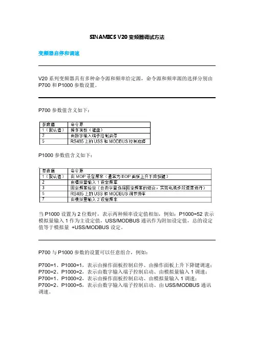
SINAMICS V20变频器调试方法变频器启停和调速V20系列变频器具有多种命令源和频率给定源,命令源和频率源的选择分别由P700和P1000参数设置。
P700参数值含义如下:P1000参数值含义如下:当P1000设置为2位数时,表示两种频率设定值相加,例如:P1000=52表示模拟量输入1作为主设定值,USS/MODBUS通讯作为附加设定值,总的设定值等于模拟量+USS/MODBUS设定。
P700与P1000参数的设置可以任意组合,例如:P700=1、P1000=1,表示由操作面板控制启停、由操作面板上升下降键调速;P700=2、P1000=2,表示由数字输入端子控制启动、由模拟量输入1调速;P700=1、P1000=2,表示由操作面板控制启动、由模拟量输入1调速;P700=2、P1000=5,表示由数字输入端子控制启动、由USS/MODBUS通讯调速。
如何实现V20变频器启动后按恒定频率运行现场应用中,很多情况下客户希望变频器启动以后以恒定的频率运行,实现恒定频率运行的方式很多,本文列举几个简单了例子供参考。
注意:这里给出的示例是基于出厂设置基础上修改的参数,不能保证任何情况下都能实现相应功能。
如何设置V20 端子启动后以恒定频率运行数字输入1(DI1))作为启动信号方法一:P700=2P1000=1P1040=期望的运行频率(例如启动后希望恒定运行于40Hz,设置P1040=40)方法二:P700=2P1000=3P1020=1P1001=期望的运行频率(例如启动后希望恒定运行于40Hz,设置P1001=40)如何设置V20操作面板启动后以恒定频率运行操作面板上的绿色按键作为启动方法一:P700=1P1000=1P1040=期望的运行频率(例如启动后希望恒定运行于40Hz,设置P1040=40)方法二:P700=1P1000=3P1020=1P1001=期望的运行频率(例如启动后希望恒定运行于40Hz,设置P1001=40)固定频率调速固定频率,也称为多段速,就是设置参数P1000=3的条件下,用开关量端子选择固定频率的组合,实现电机多段速度运行。
西门子V60、V80变频器产品详细介绍SINAMICS V60、V80伺服驱动系统西门子V80伺服驱动系统包括伺服驱动器和伺服电机两部分,伺服驱动器总是与其对应的同等功率的伺服电机一起配套使用。
SINAMICS V80 伺服驱动器通过脉冲输入接口直接接收从上位控制器发来的脉冲序列,进行速度和位置控制,通过数字量接口信号来完成驱动器运行的控制和实时状态的输出。
西门子V80伺服驱动西门子V80伺服驱动——最小化的安装尺寸,安装维护简单西门子V80伺服驱动系统概述西门子V80伺服驱动系统包括伺服驱动器和伺服电机两部分,伺服驱动器总是与其对应的同等功率的伺服电机一起配套使用。
SINAMICS V80 伺服驱动器通过脉冲输入接口直接接收从上位控制器发来的脉冲序列,进行速度和位置控制,通过数字量接口信号来完成驱动器运行的控制和实时状态的输出。
西门子V80伺服驱动是经济型运动控制系列的新成员SINAMICS V 系列为西门子专门为经济型应用设计的驱动产品系列。
这个产品系列包括经济型变频器和经济型伺服驱动器两部分。
其中属于运动控制部门的产品包括SINAMICS V10 经济型变频器和SINAMICS V60/80 经济型伺服驱动器。
西门子V80伺服驱动技术特点与优势硬件系统最小化的尺寸,节省安装空间优化的散热和通风设计,无需散热风扇标准化的接口与端子,简化安装与维护速度设定直接为脉冲输入,方便系统设计伺服驱动器与伺服电机配套设计,配合完美技术功能无需参数调试,简单易用高精度的控制脉冲,更好的满足控制的要求集成的编码器接口,可直接实现闭环控制通讯连接标准的连接电缆,与PLC 实现顺畅、可靠的连接全面的实现全集成的自动化(TIA)。

操作手册SINAMICS V80 04.2008SINAMICS V80操作手册04.2008系统准备C-11安装C-16系统接线C-18试运行C-41故障显示及处理C-43系统维护及服务C-54规格及说明C-60前言由衷感谢您购买SIEMENS公司小型伺服驱动器—SINAMICS V80。
为了您能够安全使用本伺服驱动器,请您一定阅读该使用说明书。
同时,请妥善保存该说明书,并保证把它交给最终用户。
相关资料如需要,也可以参阅下面的相关资料:• SINAMICS V80产品样本• SINAMICS V80伺服电机说明书有关安全标识本手册中有关安全的内容,使用如下标识。
有关作业安全标识的叙述,其内容十分重要,请务必遵守。
表示如果操作错误,将会导致危险情况的发生,造成死亡或重伤。
表示如果操作错误,将会导致危险情况的发生,可能会造成中等程度的受伤或轻伤,或物品损失。
表示禁止(绝对不能做的事表示强制(必须要做的事)。
例如接地时,则表示为 。
安全注意事项本节就产品到货时的确认、保管、搬运、安装、配线、运行、检查、废弃等用户必须遵守的重要事项进行说明。
确认到货产品时的注意事项保管、搬运注意事项安装注意事项配线注意事项维护与检查注意事项废弃注意事项请在使用时予以注意。
• 为了进行详细说明,本手册中的部分插图在描绘时去掉了外罩或安全保护体。
在实际运行时,请务必按规定将外罩或安全保护体安装到原来的位置,再根据本手册的说明进行运行。
• 本手册中的插图为代表性图例,可能会与您收到的产品有所不同。
• 由于产品升级、规格变更以及为提高本手册的使用便利性,我们将会适时对本手册进行更新。
请到SIEMENS网站下载或向代理商索取最新的资料。
• 对于客户自行改造的产品,本公司不对质量提供任何保证。
对于因改造产品所造成的伤害及损失,本公司概不负责。
目录前言 ……………………………………………………………………………………………………………………… C-1相关资料……………………………………………………………………………………………………………… C-1有关安全标识………………………………………………………………………………………………………… C-1安全注意事项………………………………………………………………………………………………………… C-21 系统准备 ………………………………………………………………………………… C-111.1 警示标记……………………………………………………………………………………………… C-111.2 到货检查 ……………………………………………………………………………………………… C-111.3 订货号的含义 ………………………………………………………………………………………… C-121.4 SINAMICS V80驱动器及伺服电机的订货号 …………………………………………………… C-121.5 接口模块和功能……………………………………………………………………………………… C-13指令脉冲设置 (PULSE) …………………………………………………………………………… C-13 指令滤波设置 (FIL) ……………………………………………………………………………… C-14 指令脉冲指示(REF) ……………………………………………………………………………… C-14 报警指示 (AL1 / AL2 / AL3) ……………………………………………………………………… C-152 安装 ……………………………………………………………………………………… C-162.1 安装环境 ……………………………………………………………………………………………… C-162.2 安装方法 ……………………………………………………………………………………………… C-17安装方法及方向 …………………………………………………………………………………… C-17 安装间距…………………………………………………………………………………………… C-173 系统接线 ………………………………………………………………………………… C-183.1 接线时的注意事项 …………………………………………………………………………………… C-18 电源线的保护 ……………………………………………………………………………………… C-18 有关接地的注意事项…………………………………………………………………………… C-18 有关电缆的注意事项 …………………………………………………………………………… C-18 其他注意事项 ……………………………………………………………………………………… C-19 功率损耗 …………………………………………………………………………………………… C-19 断路器及保险的容量 …………………………………………………………………………… C-20 电源滤波器 ………………………………………………………………………………………… C-213.2 系统部件一览 ………………………………………………………………………………………… C-213.3 接线图示例 …………………………………………………………………………………………… C-223.4 符合CE标记的安装和接线方法 ………………………………………………………………… C-23EMC认定的安装条件 …………………………………………………………………………… C-23 铁氧体磁芯的安装方法………………………………………………………………………… C-24 电缆的固定 ………………………………………………………………………………………… C-24 屏蔽箱 ……………………………………………………………………………………………… C-243.5 SINAMICS V80及外围设备 ………………………………………………………………………… C-253.6 SINAMICS V80供电主电路的接线 ……………………………………………………………… C-253.7 SINAMICS V80供电主电路的电线尺寸 ………………………………………………………… C-26电线的类型 ………………………………………………………………………………………… C-26 电线尺寸与允许电流…………………………………………………………………………… C-26 电源输入端子(L1、L2)和电机接线端子(U、V、W) …………………………………… C-27 接地端子 …………………………………………………………………………………………… C-27 编码器信号连接器(X2) ………………………………………………………………………… C-27 输入输出信号连接器(X1) ……………………………………………………………………… C-273.8 供电电源连接器(X10)的接线 …………………………………………………………………… C-283.9 电机电缆连接器(X20)的接线 ……………………………………………………………… C-30不带抱闸的电机 …………………………………………………………………………………… C-30 带抱闸的电机……………………………………………………………………………………… C-313.10 编码器连接器(X2)的接线 ………………………………………………………………………… C-33 带连接器标准的编码器电缆 …………………………………………………………………… C-333.11 输入输出连接器(X1)的接线 ……………………………………………………………………… C-34 标准DI/DO信号电缆的连接图 ………………………………………………………………… C-353.12 输入信号的接线举例 ………………………………………………………………………………… C-36控制器集电极开路输出的接线举例 ………………………………………………………… C-36 控制器线路驱动器输出的接线举例………………………………………………………… C-363.13 输出信号的接线举例 ………………………………………………………………………………… C-373.14 紧急停止的时序 ……………………………………………………………………………………… C-383.15 输入输出信号的说明 ………………………………………………………………………………… C-394 试运行 …………………………………………………………………………………… C-415 故障显示及处理 ………………………………………………………………………… C-435.1 报警指示灯…………………………………………………………………………………………… C-435.2 报警指示LED不亮灯时…………………………………………………………………………… C-486 系统维护及服务 ………………………………………………………………………… C-546.1 定期检查……………………………………………………………………………………………… C-546.2 部件的标准寿命……………………………………………………………………………………… C-546.3 冷却风扇的更换方法 ………………………………………………………………………………… C-55当为100 W至400 W伺服驱动器时 ………………………………………………………… C-55 当为750 W伺服驱动器时 ……………………………………………………………………… C-577 规格及说明 ……………………………………………………………………………… C-607.1 技术数据……………………………………………………………………………………………… C-607.2 信号说明……………………………………………………………………………………………… C-617.3 过载保护特性………………………………………………………………………………………… C-621.1警示标记产品的侧面标有警示标记。

1Answers for industry.SINAMICS V10 操作说明书SINAMICS V10 变频器操作说明书 • 04.20092机械安装 (3)电气安装 (6)调试 (8)参数列表 (23)故障与报警 (27)技术规格 (29)其他参考信息 ..............................31SINAMICS V10 变频器操作说明书 • 04.20093SINAMICS V10 变频器SINAMICS V10是一款多用途的经济型工业变频器,它具备了通用驱动的基本功能,可以用于控制三相交流鼠笼式异步电机。
SINAMICS V10有四种外形尺寸可供选择,其功率范围覆盖0.55kW 到22kW 。
警告本设备带有危险电压而且它所控制的是带有危险电压的转动机件。
如果不按照要求进行操作就可能会造成死亡、严重的人身伤害或重大的财产损失。
注意触电的危险。
即使电源已经切断,变频器的直流回路电容器上仍然带有危险电压,因此在电源关断5分钟以后才允许打开本设备。
如果设备正在运行,不得将设备上的端子块取下。
设备正常运行时可能会产生>3.5mA 的漏地电流。
因此,设备必须永久接地。
必须将设备垂直安装在电柜内。
如需了解更多的安全注意事项,参见《SINAMICS V10变频器操作说明 》。
安全注意事项机械安装1.安装间距可以将几个变频器并排或者上下安装在一起,其安装间距要求如下:上下安装:变频器上部和下部都应留下至少100mm 的通风间隙。
并排安装:变频器左右两侧都应留下距离至少为“A”的通风间隙(见下图)。
!2.安装方式• 壁挂式安装- 壁挂式安装为默认安装方式;- 无需使用任何安装组件;- 整个变频器直接安装在电柜内。
• 穿墙式安装- 要求使用穿墙式安装组件。
- 变频器主体安装在电柜内,散热器延伸至电柜外。
- 适用于纺织等应用场合。
- 具体安装说明见SINAMICS V10穿墙式安装组件的《产品信息》或《SINAMICS V10变频器操作说明》。
SINAMICS V10简介SINAMICS V10 是一种变频装置,拥有大量行业所需要的基本功能。
该变频器成本低、使用极为方便;采用了高可靠性设计,可以轻松应付恶劣的工作环境。
SINAMICS V10 适用于中国复杂的电力网络,尤其适用于带有电泵、风扇、纺织机械或者其它简易传输系统等的应用。
SINAMICS V10 变频器优点介绍高可靠性::-工作电压范围:400V± 15%(三相交流);-防护等级IP21,电路板设计有保护涂层;-高强度机械设计,可采用直推插式安装;-全新冷却功能设计,无需风扇,符合故障安全应用的要求。
调试方便:- 10 种设置,涵盖了各种连接模式;6 个宏指令,可以轻松应对不同应用。
- BOP 面板支持中文,具备强大的参数克隆功能。
安装简易:-采用了标准连接器设计(带标记)-BOP 支持柜门安装,且拥有强大的参数克隆功能To the top of the pageSINAMICS V10 变频器技术数据电压范围三相交流 400V; -15% ~ +15%;功率范围0.55 kW ~22 kW工作环境0°C 至+60°C控制方式线性 V/f 控制(带可编程电压启动功能)、平方 V/f 控制;磁通电流控制(FCC)输出频率0Hz ~ 300Hz载波频率2kHz ~ 16kHz3 点数字量输入/ 1 点数字量输出数字量输入/输出1点模拟输入 / 1 点模拟输出(电压型或电流型)模拟量输入/输出过载能力可达150% 额定电流,持续时间 60 秒;重复周期时间 300 秒内置功能PI 控制器、快速电流限制(FCL)、转矩起动、自动重启、快速起动等。
SINAMICS V20 基本型变频器概述SINAMICS V20——经济、可靠、易用的基本型变频器基本型变频器SINAMICS V20向小型OEM客户提供最适合的经济型解决方案。
SINAMICS V20有四种外形尺寸可供选择(FSA~FSD),提供三相400V和单相230V进线两种规格,分别可覆盖0.12~3kW,0.37~15kW的功率范围。
SINAMICSSINAMICS V20 multi-pump control 08/2019O perating ManualSiemens AGDigital IndustriesPostfach 48 48A5E43416874-003 Ⓟ09/2019 Subject to change Copyright © Siemens AG 2017. All rights reservedLegal informationWarning notice systemThis manual contains notices you have to observe in order to ensure your personal safety, as well as to preventdamage to property. The notices referring to your personal safety are highlighted in the manual by a safety alertsymbol, notices referring only to property damage have no safety alert symbol. These notices shown below aregraded according to the degree of danger. indicates that death or severe personal injury will result if proper precautions are not taken. WARNING indicates that death or severe personal injury may result if proper precautions are not taken. CAUTIONindicates that minor personal injury can result if proper precautions are not taken. NOTICE indicates that property damage can result if proper precautions are not taken.If more than one degree of danger is present, the warning notice representing the highest degree of danger willbe used. A notice warning of injury to persons with a safety alert symbol may also include a warning relating toproperty damage.Qualified PersonnelThe product/system described in this documentation may be operated only by personnel qualified for the specifictask in accordance with the relevant documentation, in particular its warning notices and safety instructions.Qualified personnel are those who, based on their training and experience, are capable of identifying risks andavoiding potential hazards when working with these products/systems.Proper use of Siemens productsNote the following: WARNINGSiemens products may only be used for the applications described in the catalog and in the relevant technicaldocumentation. If products and components from other manufacturers are used, these must be recommendedor approved by Siemens. Proper transport, storage, installation, assembly, commissioning, operation andmaintenance are required to ensure that the products operate safely and without any problems. The permissibleambient conditions must be complied with. The information in the relevant documentation must be observed.TrademarksAll names identified by ® are registered trademarks of Siemens AG. The remaining trademarks in this publicationmay be trademarks whose use by third parties for their own purposes could violate the rights of the owner.Disclaimer of LiabilityWe have reviewed the contents of this publication to ensure consistency with the hardware and softwaredescribed. Since variance cannot be precluded entirely, we cannot guarantee full consistency. However, theinformation in this publication is reviewed regularly and any necessary corrections are included in subsequenteditions.Table of contents1 Overview (5)2 Pump switch-in/switch-out (7)3 Stop mode (15)4 Pump switchover (17)5 Service mode (19)6 Faults and alarms (21)SINAMICS V20 multi-pump controlTable of contentsSINAMICS V20 multi-pump controlSINAMICS V20 multi-pump controlOverview 1Multi-pump control is suitable for applications that require simultaneous operation of up tofour pumps, for example, equalizing significantly fluctuating water pressures or flow rates.After the multi-pump control is enabled, you can configure the following four sub-functionsbased on your particular requirements: switching-in/out, stop mode, pump switchover, andservice mode.NoteTo control more than two pumps simultaneously, you must connect an optional I/O ExtensionModule to expand the number of V20 I/O terminals. For more information about this optionmodule, see Section "I/O Extension Module" in "SINAMICS V20 Converter Operating Instructions".Enabling the functionTo enable this function, you must first make sure that the firmware version of the V20converter is 3.94 or later. Then, use the optional Parameter Loader and an SD card todownload the multi-pump control script files into the converter. For more information aboutthe Parameter Loader and the SD card, see Section "Parameter Loader" in "SINAMICS V20Converter Operating Instructions".Proceed through the following steps to download the script files into the converter:1.2.3.Create a folder named "romfs" under the root directory of the SD card and place"autorun.lua" and "utils.lua" in the folder.4.Fit the Parameter Loader to the converter, and then insert the SD card into the Parameter Loader.5.Power on the converter, and data transfer starts automatically. The converter displays"Updating" during the transfer.6.After a successful transfer, the converter displays "Update complete". If any fault or alarm occurs during the transfer, see Section "Faults and alarms (Page 21)" or Section "Faults and alarms" in "SINAMICS V20 Converter Operating Instructions" for possible reasons and remedies.7.Remove the Parameter Loader and re-power on the converter. Then you can enable the multi-pump control function by setting P4002 = 1.You can obtain the "SSTAGE.bin" file from the corresponding firmware updating package.Make sure that the version of the firmware updating package to be downloaded and theversion of your V20 firmware are the same.NoteOverviewSINAMICS V20 multi-pump controlNote•Make sure that the function-specific script files you use is downloaded from the previous Internet address. Otherwise, alarm A650 may appear reminding you that this script is not an officially released script. Also, you can download the "SINAMICS V20 Converter Operating Instructions" from the link.•After you successfully download the script files into the converter, all parameters used for this function are automatically set to their default settings. Note that the default settings of parameters P0731, P0732, P0733, P0734, P0840, P0845, P1200, and P2200, which are different from their factory defaults, are changed to adapt to the function. To make sure that the multi-pump control function runs properly, do not manually set the values of P0840 and P0845 after the function is enabled.•Multi-pump control uses PID controller-specific parameters. For more information about how to configure those parameters, see Section "Setting the PID controller" in "SINAMICS V20 Converter Operating Instructions".•If you use the motor staging function on the converter, this function is automatically disabled after the multi-pump control function is enabled.Setting parametersNoteYou can only use digital input 1 as the ON/OFF control source, related to r4000.0.NoteTo enable the multi-pump control function automatically after each converter power-on,make sure that both P4002 and P4004 are set to "1".SINAMICS V20 multi-pump controlPump switch-in/switch-out 2The converter uses four relays (KP1 to KP4), which are connected to digital outputs DO1 to DO4, to switch pumps in and out according to the PID error (r2273). In addition, two groups of contactors, KDs and KMs, are used to switch the pumps between converter operation and line system operation. Soft pump switching can be realized as all motors start/stop with ramp speeds, so as to minimize the shock to the pipes.Main circuitNote The maximum voltage on DO1 is ± 35 V DC. The maximum load current on DO1 is 100 mA.Pump switch-in/switch-outSINAMICS V20 multi-pump controlExternal control circuitPump switch-inIf the pump controlled by the converter runs at the maximum speed (P1082) and the PID error is higher than the switch-in threshold (P2373) and lower than the delay overridethreshold (P2376) for a specified time (P2374), the converter first switches the pump from converter operation to line system operation, and then switches on an idle pump which is softly started with a ramp-up speed and runs in converter operation.NoteIf the PID error rises above the switch-in delay override threshold (P2376), the converter skips the switch-in delay (P2374) and performs the switch-in operation immediately.Pump switch-in/switch-outSINAMICS V20 multi-pump controlParameter P4012 is used to control the selection mode of the next pump that is softly started by the converter. Bits 01 to 04 of r4000 control the pump which is selected to run depending on P4012.●P4012 = 0: Selecting the next pump according to the fixed sequence. The converterswitches in the pump by following the sequence M1, M2, M3, to M4.●P4012 = 1: Selecting the next pump according to the operating hours. The converterswitches in the pump with the least absolute operating hours (r4026 to r4029).Pump switch-in/switch-outPump switch-outIf the pump controlled by the converter runs at a speed lower than the frequency switch-outthreshold (P4014 + P1080) and the PID error is lower than the PID error switch-out threshold(-P2373) for specified time (P2375), the converter first switches off the pump (OFF2) whichruns in converter operation, and then captures a running pump and switches it from linesystem operation to converter operation. Parameter P4012 is used to control the selectionmode for switching in/out motors.●P4012 = 0: Selecting the next pump according to the fixed sequence. The converterswitches out the pump by following the sequence M4, M3, M2, to M1.●P4012 = 1: Selecting the next pump according to the operating hours. The converter firstswitches out the pump with the most absolute operating hours (r4026 to r4029).NoteIf the PID error drops below the switch-out delay override (-P2376), the converter skips theswitch-out delay (P2375) and performs the switch-out operation immediately.SINAMICS V20 multi-pump controlPump switch-in/switch-out Pump switch-out based on the fixed sequence (P4012 = 0)Pump switch-in/switch-outPump switch-out based on the absolute operating hours (P4012 = 1)Pump switch-in/switch-out Setting parametersPump switch-in/switch-outStop mode3 Two stop modes are available as follows:●Normal stop: All pumps running in line system operation are switched off at the same timeas soon as the stop command is received. The pump in converter operation stops underthe control of the converter.●Sequence stop: The pumps running in line system operation stop one by one in thereverse sequence in which they are switched on. There is a delay time between everypump stop. The pump in converter operation stops under the control of the converter afterthe other pumps are switched off.After the OFF command is received, the pumps are switched off in either of the two stopmodes:●With OFF1 command received, the pump stop mode is selected in P2370 as follows:–P2370 = 0: normal stop–P2370 = 1: sequence stopWith OFF2/OFF3 command received, the pumps are switched off with normal stop.●Stop mode Setting parametersPump switchover 4With pump switchover enabled, the converter monitors the operation status of all runningpumps.●If the continuous operating hours of the pump in converter operation exceed the threshold(P4024), the converter switches off the pump and then switches in an idle pump to keepconstant output power.●If the continuous operating hours of a pump in line system operation exceed the threshold(P4024), the converter first switches off the pump, switches out the directly controlledpump from converter operation to line system operation, and switches in an idle pump tokeep constant output power.You can use parameter P4012 to define the selection mode for the next pump. The internalcounters (r4026 to r4029 and r4031 to r4034) are used to calculate the operating hours ofthe pumps.●P4012 = 0: Selecting the next pump according to the fixed sequence. The converter firstswitches out the pump with most continuous operating hours (r4031 to r4034) and thenswitches in the pump following the sequence M1, M2, M3, to M4.●P4012 = 1: Selecting the next pump according to the operating hours. The converter firstswitches out the pump with the most continuous operating hours (r4031 to r4034) andthen switches in the pump with the least absolute operating hours (r4026 to r4029).Setting parametersPump switchoverService mode5 You can use parameters P4016 to P4019 to set the pumps in service mode respectively.When a pump is in service mode, the converter locks the corresponding relay, which allowsyou to perform troubleshooting of this pump without interrupting the operation of otherpumps.WARNINGDanger to life due to unconnected low-voltage circuit breakersIf a pump is not connected to the mains and converter through a low-voltage circuit breaker,troubleshooting the pump in service mode can result in electric shock and unexpectedmovement of the pump, causing serious personal injury or death.•Make sure that all pumps are connected to the mains and converter through low-voltage circuit breakers. After a pump is set in service mode, cut off its low-voltage circuitbreaker before performing any troubleshooting operation.Setting parametersService modeFaults and alarms6 AlarmA650Unofficial script running The script running is not approved and should not be used. Use an officially released script.SINAMICS V20 multi-pump controlOperating Manual, 08/2019, A5E43416874-003 21。
阐述SINAMICS V80伺服驱动系统1 SINAMICS V80的介绍SINAMICS V80伺服驱动系统是西门子专为小型简易机械开发的经济型伺服驱动产品。
SINAMICS V80伺服驱动系统价格经济,设定简易便捷,无需参数化的配置方式,可与SIMATIC S7-200系列PLC组成简单的运动控制系统。
SINAMICS V80伺服驱动系统包括伺服驱动器和伺服电机两部分,伺服驱动器总是与其对应的同等功率伺服电机一起配套使用。
SINAMICS V80 伺服驱动器通过脉冲输入接口来接受从上位控制器发来的脉冲序列,进行速度和位置的控制,通过数字量接口信号来完成驱动器运行的控制和实时状态的输出。
图1 V80伺服驱动器接口图通过“指令脉冲设置(PULSE)”旋转开关,可以设定驱动器的指令脉冲分辨率、指令脉冲连接方式和指令脉冲类型。
与SINAMICS V80 驱动器相匹配的伺服电机有4种,功率分别是100W、200W、400W和750W,每种电机都有带抱闸和不带抱闸两款。
电机类型为永磁同步电机,采用自然风冷方式,电机表面无涂漆,电机输出轴带键槽。
2 EM253的技术特点S7-200 EM253定位模块用来对单轴步进电机进行开环速度、位置控制,无法实现闭环控制;提供从12Hz到200kHz的脉冲输出频率;控制系统的测量单位可以采用脉冲数,也可以采用工程单位(如:英尺、厘米);具有绝对方式、相对方式和手动方式三种工作模式;提供连续的位置控制工程,最多可以支持25个位置点的控制,每段运动轨迹包络最多可以有4种运动速度;提供螺距补偿功能;提供4种不同归零模式。
EM253集成有5个数字输入点(STP,停止;RPS,参考点;ZP,零脉冲信号;LMT+,正方向限位信号;LMT-,负方向限位信号),6个数字输出点(DIS、CLR、P0+、P1+、P0-、P1-)。
通过S7-200PLC的扩展接口,实现与CPU间通讯控制。
3SINAMICS V10变频器操作说明书 • 04.2009Answers for industry.SINAMICS V10 操作说明书SINAMICS V10 变频器操作说明03/2009文档版本:03/2009操作面板固件版本:V01.08法律资讯警告提示系统为了您的人身安全以及避免财产损失,必须注意本手册中的提示。
人身安全的提示用一个警告三角表示,仅与财产损失有关的提示不带警告三角。
警告提示根据危险等级由高到低如下表示。
危险表示如果不采取相应的小心措施,将会导致死亡或者严重的人身伤害。
警告表示如果不采取相应的小心措施,可能导致死亡或者严重的人身伤害。
小心带有警告三角,表示如果不采取相应的小心措施,可能导致轻微的人身伤害。
小心不带警告三角,表示如果不采取相应的小心措施,可能导致财产损失。
注意表示如果不注意相应的提示,可能会出现不希望的结果或状态。
当出现多个危险等级的情况下,每次总是使用最高等级的警告提示。
如果在某个警告提示中带有警告可能导致人身伤害的警告三角,则可能在该警告提示中另外还附带有可能导致财产损失的警告。
合格的专业人员仅允许安装和驱动与本文件相关的附属设备或系统。
设备或系统的调试和运行仅允许由合格的专业人员进行。
本文件安全技术提示中的合格专业人员是指根据安全技术标准具有从事进行设备、系统和电路的运行,接地和标识资格的人员。
按规定使用 Siemens 产品请注意下列说明:警告Siemens 产品只允许用于目录和相关技术文件中规定的使用情况。
如果要使用其他公司的产品和组件,必须得到Siemens 推荐和允许。
正确的运输、储存、组装、装配、安装、调试、操作和维护是产品安全、正常运行的前提。
必须保证允许的环境条件。
必须注意相关文件中的提示。
商标所有带有标记符号 ® 的都是西门子股份有限公司的注册商标。
标签中的其他符号可能是一些其他商标,这是出于保护所有者权利的目地由第三方使用而特别标示的。
SINAMICS V10简介SINAMICS V10 是一种变频装置,拥有大量行业所需要的基本功能。
该变频器成本低、使用极为方便;采用了高可靠性设计,可以轻松应付恶劣的工作环境。
SINAMICS V10 适用于中国复杂的电力网络,尤其适用于带有电泵、风扇、纺织机械或者其它简易传输系统等的应用。
SINAMICS V10 变频器优点介绍高可靠性::-工作电压范围:400V± 15%(三相交流);-防护等级IP21,电路板设计有保护涂层;-高强度机械设计,可采用直推插式安装;-全新冷却功能设计,无需风扇,符合故障安全应用的要求。
调试方便:- 10 种设置,涵盖了各种连接模式;6 个宏指令,可以轻松应对不同应用。
- BOP 面板支持中文,具备强大的参数克隆功能。
安装简易:-采用了标准连接器设计(带标记)-BOP 支持柜门安装,且拥有强大的参数克隆功能To the top of the pageSINAMICS V10 变频器技术数据电压范围三相交流 400V; -15% ~ +15%;功率范围0.55 kW ~22 kW工作环境0°C 至+60°C控制方式线性 V/f 控制(带可编程电压启动功能)、平方 V/f 控制;磁通电流控制(FCC)输出频率0Hz ~ 300Hz载波频率2kHz ~ 16kHz3 点数字量输入/ 1 点数字量输出数字量输入/输出1点模拟输入 / 1 点模拟输出(电压型或电流型)模拟量输入/输出过载能力可达150% 额定电流,持续时间 60 秒;重复周期时间 300 秒内置功能PI 控制器、快速电流限制(FCL)、转矩起动、自动重启、快速起动等。
SINAMICS V20 基本型变频器概述SINAMICS V20——经济、可靠、易用的基本型变频器基本型变频器SINAMICS V20向小型OEM客户提供最适合的经济型解决方案。
SINAMICS V20有四种外形尺寸可供选择(FSA~FSD),提供三相400V和单相230V进线两种规格,分别可覆盖0.12~3kW,0.37~15kW的功率范围。
高可靠性设计,创新的冷却设计,经久耐用。
无需调试软件,通过简单参数设定即可实现预定功能。
内置常见的连接宏与应用宏,简化操作,开箱即用。
丰富的I/O接口,直观的LED面板显示,完善的集成功能,可以方便地应用在风机、泵、传送装置及搅拌机、混料机等设备中。
同时,创新的节能方式及节能结果显示,真正意义上节省费用。
设计典型应用风机、泵类应用• 离心泵• 风扇• 压缩机等SINAMICS V20提供强大的常见的风机、泵类应用功能及强大的保护功能,非常适合此类应用。
•水泵气穴保护•针对水泵堵塞的多脉冲高转矩启动以及防堵模式•用于调节工艺数值的PID控制器(例如,温度、压力、水平、流量)•多泵控制功能通过额外增加两个定速驱动(级联)来扩大流量范围•霜冻和冷凝保护功能防止电机在极端环境条件下受潮搬运类应用•带式输送机•辊式输送机•链式输送机SINAMICS V20丰富了在启动加速和制动停止应用上的功能,大大方便了搬运类的应用。
•斜坡时间可调,平稳加速,减少对对齿轮单元、轴承、滚筒和辊轴的压力•单脉冲高转矩启动功能适用于带有较高启动转矩的传送带•通过使用制动电阻或直流制动功能实现动态性能•通过监控负载转矩实现皮带损坏检测加工类应用•加工制造业中的单个驱动。
例如,轧钢机,搅拌机,捏炼机,破碎机,搅动机,离心分离机等•加工机器中带机械连动抽的主要驱动。
例如,用于加工纺织品,绳索和线缆的环锭纱纺机,编织机等对于连续加工类应用,SINAMICS V20强大的功能充分满足在高性能和节能方面的需求。
•异常不停机模式能够保证不间断的加工生产,从而实现较高的生产率•通过共直流母线对再生能量进行转换•单脉冲高转矩启动功能适用于带有较高启动转矩的机器•适合于纺织的摆频功能To the top of the page产品亮点及客户受益易于安装•- 壁挂式安装及穿墙式安装均可实现紧凑的并排安装- 无需额外组件即可正常运行•通讯灵活- 变频器端子可用作通讯端口- 连接宏中预设了用于USS和MODBUS RTU通讯的参数,调试便捷•制动高效- 集成直流制动,复合制动- 通过制动单元及制动电阻可实现能耗制动,且制动电阻占空比可在5 %到100 %之间调节- ≥ 7.5 kW的变频器集成内置制动模块,此类变频器可以直接连接制动电阻易于使用•参数克隆/版本升级使用BOP(基本操作面板)接口模块或参数下载器(使用参数下载器可不接主电源)能够轻松实现两台变频器之间的参数传输,缩短及简化调试过程•宏方法- 内置常用的连接宏与应用宏,简化配置,快速调试•稳定可靠- 更宽的电压范围、更好冷却设计以及带涂层的PCB板大大提升了变频器在恶劣环境中的稳定性- 保证在以下总线电压范围内可靠运行:- 1AC 200 V … 240 V (-10 % / +10 %)- 3AC 380 V … 480 V (-15 % / +10 %)- 运行时的环境温度最高可达60 °C•运行过程中节能——ECO模式- 内置用于V/f和V2/f控制的节能模式通过自动调节磁通电流实现节能- 变频器支持以kWh、CO2甚至当地货币单位来显示能耗数值•运行过程中节能——DC共联- 相同额定功率的SINAMICS V20变频器可以共用同一直流总线,能量再利用- 减少对能耗制动以及外接组件的需求•运行过程中节能——休眠模式- 变频器和电机仅在工厂或机器需要时才运行- 节能,延长电机使用寿命SINAMICS V50 高品质单机驱动变频调速柜综述全新设计节能首选SINAMICS V50 高品质单机驱动变频调速柜是西门子公司新推出的又一款低压交流变频器,典型应用为风机和泵。
紧凑的柜体机构,高度模块化设计,成就了高品质柜式装置,并通过了严格的整机测试,具有极高的性价比。
应用SINAMICS V50 高品质单机驱动变频调速柜适用于多种变转矩负载的单机传动应用,包括平方转矩、线性转矩及恒功率负载类型,典型应用如下:- 风机- 泵SINAMICS V50 高品质单机传动变频调速柜满足电力、水及污水处理、石油化工、水泥、矿山、冶金、船舶等行业标准,特别具有电力行业专用配置。
高品质柜式装置- 柜式装置-保证变频系统整体的高品质- 紧凑的柜体设计-节省占地面积达30%- 采用高品质柜体- 柜内采用高品质低压元件- 柜内配置强电保护- 通过严格整机测试更多标准配置8MF 机柜标准保护等级IP20操作面板BOP电源输入端子电机输出端子进线主开关及快熔保险输入电抗器EMC(2 类工业环境)滤波器功率单元(集成整流,直流及逆变环节)冷却风扇主控板RS485 接口模拟量/数字量输入输出端子接口板强电保护板SINAMICS V60概述•SINAMICS V60 信息•SINAMICS V60 技术数据SINAMICS V60 产品信息SINAMICS V60与提供脉冲/方向信号的数控系统配合,为经济型车床及铣床提供完整解决方案。
SINAMICS V60主要适合于注重经济性的简单应用场合,完善了SINUMERIK 801与SINUMERIK 802S base line的系统解决方案。
SINAMICS V60驱动系统包含有CPM60.1单轴驱动模块和1FL5交流伺服电机以及配套电缆。
驱动模块只能与功率相匹配的伺服电机配套使用。
由于驱动、电机组合在出厂前已经预调到最佳配置,所以可大大节省驱动系统的现场调试时间。
To the top of the pageSINAMICS V60 技术数据CPM60.1 进线电压3相交流 220V – 240V额定额定输出电流4A 6A 7A 10A 1FL5 Motor 额定转矩4Nm 6Nm 7.7Nm 10NmSINAMICS V80概述•SINAMICS V80 信息•SINAMICS V80 –技术数据SINAMICS V80 产品信息这种全新设计的伺服驱动系统,性价比高,带有脉冲接口,适于定位型应用。
SINAMICS V80 采用了全新的伺服驱动技术,无需设置任何参数,无需增益调节,便可以实现极高的定位精度。
SINAMICS V80 的调试出人意料地简单:组件连线工作完成之后,仅需采用旋转式开关选择设定点分辨率即可。
系统集成有自动调节功能,可以根据所连接的机器,自动调整闭环控制器的参数设置,且对负载变化的响应极为快捷。
系统还另外设计有一个旋转开关,可以根据具体应用,精细地调整驱动器的动态行为特性。
伺服驱动结构极紧凑,高仅120mm(含所有选用电源规格)、宽从35mm 至70mm,可以提供100W 至750W的功率。
本驱动器设计有基准脉冲接口,与任何一款带有脉冲输出接口的标准控制器(例如S7-200 PLC)均可以构成理想的定位应用解决方案。
SINAMICS V80 –技术数据。