HDMI矩阵说明书
- 格式:doc
- 大小:1.50 MB
- 文档页数:10
一、高清混合矩阵切换器(HDMI)原理矩阵的接口分为信号输入\输出接口,INPUT 部分为信号输入端,OUTPUT部分为信号输出端。
将信号源(如电脑、DVD机)设备的输出端接入矩阵输入端(INPUT),将矩阵输出端(OUTPUT)接至信号使用设备(如投影机、电视机)的输入接口。
主要按键1、Cancel键(取消键)在任何页面按“Cancel”都会回到待机画面状态。
2、ENTER键(确认键)相当于电脑的回车键,表示进入、确认3、VIDEO键(视频键)视频切换模式按钮4、AUDIO键(音频键)音频切换模式按钮5、AV键(音视频键)音视频同步切换模式按钮6、ALL:所有按钮,输入端口对所有输出端口时使用7、SWITCH切换键按Switch 键进入切换菜单,多次按此键,可以在VIDEO、AUDIO、AV 模式切换。
7.1 AV SWITCH,音视频同时切换。
在这个状态下,用数字键输入输入通道号和输出通道号,然后按OK(Enter)键,实现切换7.2 VIDEO SWITCH,只切换视频,而不切换音频7.3 AUDIO SWITCH,只切换音频,而不切换视频7.4 AV TO ALL,把某路输入音视频同时切换到所有输出7.5 AV N TO N,进行一对一切换,1到1,2到2,3到3,······n到n其它按键(选择了解)POWER:电源指示灯 RUN:矩阵工作指示灯 IR:红外遥控接收头窗口 SAVE:模式保存按钮 MODE:模式调用按钮 ALL:所有按钮,输入端口对所有输出端口时使用 F1:自定义键(默认一一对应) FUN键(功能键):进入功能菜单,多次按此键可以在对应功能间切换。
操作步骤1、通过HDMI接口,将笔记本(信号源)与一号桌插相连。
注:一号桌插对应HDMI矩阵的一号输入口。
2、在矩阵待机状态下两次按SWITCH切换键,出现以下界面:3、在问号处键入数字1,因为步骤1中选择的是1号桌插。
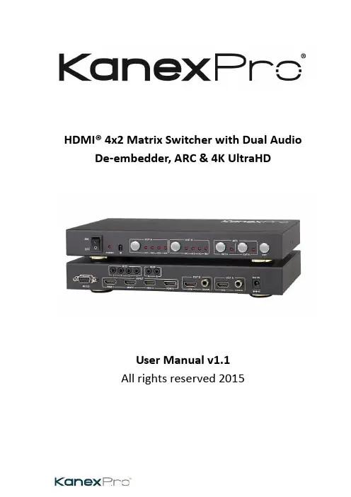
HDMI® 4x2 Matrix Switcher with Dual Audio De-embedder, ARC & 4K UltraHDUser Manual v1.1All rights reserved 20151.IntroductionThis is a high performance HDMI Matrix with four HDMI inputs & two outputs, it allows any source (Blue-Ray player, HD DVD player, satellite receiver, game system, etc.) to be shown on the any of the two displays simultaneously, and supports 4K×2K, 3D, 12-bit Deep Color. With its 3Gbps bandwidth and the additional features of the latest HDMI standards you can be sure of great HDMI distribution. It support dual ARC and wide band IR extend function also.2.FeatureCompliant with HDMI 1.4,HDCP 1.4Supports multiplexed HDMI 4-input and 2-outputSupports video format up to 4k2k@30Hz with 24bit RGB/YCbCr 4:4:4/YCBCR 4:2:2, and up to 4k2k@60Hz with 12bit YCBCR 4:2:0.Deep Color support 48/36/30/24-bitSupports reception of any audio data conforming to the HDMI specification such PCM at up to 192kHz, compressed audio (IEC 61937), DSD, DST, DTS and HBR.Supports Dual ARC controlSuper wideband IR control system, IR transport channel can be forward or backward. Supports button,IR,RS232 etc various controlled ways;3.Package Contents4x2 HDMI Matrix 1pc5V/1A DC power adaptor 1pcRemote Control 1pcOperation Manual 1pcWideband IR Tx 4pcWideband IR Rx 2pcRS232 Cable 1pc4.SpecificationVideo Bandwidth297MHz/2.97 GbpsInput Ports 4 × HDMI (Female type)Output Ports 2 × HDMI (Female type)Output Resolution480i ~1080p50/60, 4Kx2K@24/30, VGA~UXGAHDMI Cable in1080p/12bits (15m)HDMI Cable out1080p/12bits (15m)ESD Protection±8 kV (air-gap discharge)Human Body model: ±4 kV (contact discharge)Power Supply 5 V/1A DC (US/EU standards, CE/FCC/UL certified) Dimensions113 mm (W) × 260 mm (D) × 26 mm (H)Weight750 gChassis Material MetalSilkscreen Color BlackOperating Temperature0 °C~40 °C/ 32 °F~104 °FStorage Temperature−20 °C ~ 60 °C/−4 °F ~140 °FRelative Humidity20~90 % RH (non-condensing)Power Consumption 2.0 W5.Operation and Functions5.1 Front panel1.ON/OFF: Power on/off switch.2.POWER LED: This red LED illuminates when the device is connected with powersupply.3.IR: Remote control receiver window.4.OUT A: These red LED illuminates when the output A channel select to thecorresponding input.5.OUT B: These red LED illuminates when the output B channel select to thecorresponding input.6.ARC: Press this button to select OUT A or OUT B Coaxial audio from source or HDTV. ARC function: If you need use ARC, your HDTV must support this function, when you open the ARC function, the Coaxial of the matrix will output the HDTV current display content audio. Otherwise will output the matrix input source audio.7.RST BUTTON: Press this button the matrix setting will recover to factory state.5.2 Rear panel1.RS232: Connect the RS232 port to the PC or notebook by RS232 Cable to control thematrix.2.Input:This slot is where you connect the HDMI source output from Blu-ray, PS4,Set-top Box or a laptop.3.IR TX: Connect the IR Blaster cable included in the package for IR signal transmission.Pace the IR blaster in direct line-of-sight of the equipment to be controlled.4.IR RX: Connect to the IR Receiver for IR signal reception. Ensure that remote beingused is within the direct line-of-sight of the IR receiver.5.OUT B:The HDMI is where you connect the HDTV or monitor with HDMI cable forinput source display. The Coaxial audio output is where you connect to the amplifier with coaxial cable.6.OUT A:The HDMI is where you connect the HDTV or monitor with HDMI cable forinput source display. The Coaxial audio output is where you connect to the amplifier with coaxial cable.7.DC 5V: Plug the 5V1A DC power supply into the unit and connect the adaptor to ACwall outlet.5.3 Connect and Operate1. Connect the signal sources such as Blu-Ray Players, Play Station 3, audio/video receiver, satellite receivers and computers equipped with HDMI output interfaces with a short high-speed HDMI cable to the HDMI Matrix inputs.2. Connect the HDMI output from the HDMI Matrix to a high-definition display device such as HDTV, 4K Ultra HDTV or projectors with HDMI input interfaces. Use high-speed HDMI cables that are recommended for the distances that are required for each connection.3. The Matrix is powered by an external power supply that is included. Connect power first to the source, then to the Matrix and then to each HD TV or projector.4. The input source can be controlled from the display. This is accomplished by using an optional IR Receiver pigtail pointing away from the display(s), which can be connected with the optional HDMI IR Adapter, and inserted between the HDMI cable connector and the display with the toggle switcher at the “IR” posit ion. The IR Transmitter pigtail is then connected to the Matrix and pointed to the source(s). A remote control is used at the display to select switch inputs and output. The matrix also has the capability of being controlled via Remote control.5.4 Wideband IR (30 KHz---60 KHz) introductionIR BLASTER (TX)To control the source:Plug IR Blaster into IR TX port of transmitter unit; place blaster in front of the IR eye of the source.IR RECEIVER (RX)To control the source:Plug IR Receiver into IR RX port of receiver unit; place receiver at or near display.6.Remote ControlOUTPUT A: Press IN1\IN2\IN3\IN4 button will fast switch to selectinput source to HDMI OUTPUT A, and the LED will indicate thecorresponding input source. Press button OUTPUT A will cyclefrom input IN1\IN2\IN3\IN4.OUTPUT B: Press IN1\IN2\IN3\IN4 button will fast switch to selectinput source to HDMI OUTPUT B, and the LED will indicate thecorresponding input source. Press button OUTPUT B will cyclefrom input IN1\IN2\IN3\IN4.7. RS-232 Control guide using a PCInstallationThe PC controller is green software. Just use a cable to connect the PC via RS232 port and copy “4x2 HDMI matrix Controller.exe” to PC to complete installation.Preparation1. Connect PC and multi-viewer by RS232 cable2. Power-up multi-viewer3. Double click 4x2 HDMI matrix Controller.exe icon to run itGeneral Page1.Select RS232 COM port2.Click to connect or disconnect PC and Matrix3.Click to refresh device status: include device information and Input/Output Settings on“Matrix” page4.Click to clear device information5.Click to reset to the factory settingsEDID PageThe controller has 3 methods to set the EDID mode. Manual mode, Copy mode and open EDID file mode.1.Select the needed EDID to input port and click set button the EDID will write to theselected HDMI input ports.2.Copy the selected HDMI output or HDBT output EDID and click set button to write tothe selected HDMI input ports.3.Open the user define EDID file and click set button to write to the selected HDMI inputports.4.Click the status button to refresh input EDID status.Matrix Page1.LED which display Input number for respective Output2.Click to select Input port for respective Output port3.Click to select previous or next Input port for respective Output port4.Click to open or close output ARC functionFirmware Upgrade Page1.Click to open FW file (file extension is “.fw”)2.Click to upgrade the Matrix software3.Display the message of the software upgrade process.8.Connection DiagramWarrantyB.KanexPro TM warrants that (a) its products (the “Product”) will perform greatly inagreement with the accompanying written materials for a period of 3 years from the date of receipt and (b) that the product will be free from defects in materials and workmanship under normal use and service for a period of 1 year.C.Customer RemediesKanexPro entire liability and Customer’s exclusive remedy shall be, at KanexPro option, either return of the price paid for the product, or repair or replacement of the Product that does not meet this Limited Warranty and which is returned to Kanex Pro with a copy of customers’ receipt. This Limited Warranty is void if failure of the Product has resulted from accident, abuse, or misapplication. Any replacement Product will be warranted for the remainder of the original warranty period or 90 days whichever is longer.D.NO LIABILITY FOR DAMAGESTo the maximum extent permitted by applicable law, kanex Pro disclaims all other warranties, either express or implied, including, but not limited to implied warranties of merchantability and fitness for a particular purpose, with regard to product and any related written materials. This limited warranty gives customers specific legal rights. Customers may have other rights depending on the jurisdiction.E.NO LIABILITY FOR DAMAGESTo the maximum extent permitted by applicable law, in no event shall Kanex Pro be liable for any damages whatsoever (Including without limitation, special, incidental, consequential, or indirect damages for personal injury, loss of business profits, business interruption, loss of business information, or any other pecuniary loss) arising out of the use of or inability to use this product, even if Kanex pro has been advised of the possibility of such damages.SupportKanexPro Technical and Customer support inquiries can be sent electronically via the following avenues:Tech Support Inquiry: /support/Email: ********************KanexPro Customer support can be reached via phone at (888) 975-1368 (International Calls: 1-714-332-1682) during the following times:Monday – Friday: 6:00 am – 5:00 pm PST。


HDMIMATRIX多路数字视频切换矩阵说明书装机必读为了确保矩阵切换器可靠使用及人员的安全请在安装使用和维护时敬请遵守以下事项:1. 冬春季是很容易产生静电的季节,在不经意间造成芯片的损坏,希望能够对静电问题引起重视。
加强静电防护。
2.与矩阵相连的所有机器必须共地,防止地电位差烧坏机器。
3.输入信号幅度不大于标称幅度。
大于标称幅度的输入,机器安全不能保障。
4.机器输入和输出阻抗均满足100欧姆差分阻抗,输出负载不能短路。
5.在下列操作之前一定要将矩阵切换器的电源关闭:(1)取下或重装矩阵切换器的任何部件;(2)断开或重接矩阵切换器的任何电器插头或其它连接。
6.在矩阵切换器安装时应确保电源线中的地线接地良好,请勿使用两芯电源插头, 确保矩阵切换器的输入电源为220V±10%,50Hz 的交流电。
7.矩阵切换器内有交流220V 高压部件,勿擅自打开机壳,以免发生触电危险。
8.应将矩阵切换器安装在远离电磁辐射严重的地方。
9.应让矩阵切换器工作在通风良好的环境,以免温度过高而损坏机器。
10.长时间不使用时应关闭矩阵切换器的电源。
11.非专业人士未经许可,请不要试图拆开矩阵切换器机箱,不要私自维修,以免发生意外事故或加重矩阵切换器的损坏程度。
1.概述HDMI MATRIX数字视频矩阵切换器是为了将计算机数字视频信号进行重新分配和组合的矩阵交换设备,该设备可将多路HDMI数字视频输入信号切换到多路输出通道的任意通道上去。
可广泛用于所有需要进行HDMI信号分配和组合的场合,应用领域涉及军工、多媒体教学、电视电话会议、金融、科研、气象等领域。
2.性能特点⊙插卡式工业机箱,输入输出独立插卡,一卡2路,灵活可靠。
⊙断电现场保护。
⊙可带电拔插,工作可靠。
⊙带RS232接口,可远程计算机操作。
⊙自动EDID,所有输入口的EDID信息自动同步到第1个输出显示单元的EDID。
⊙输入信号丢失LED指示。
⊙兼容HDMI1.3,支持HDCP。
高清视频网络矩阵使用说明书HN-HVLM-24/48Ver:1.0优点:1、任意输入口、输出口设置2、支持HDMI、DVI、VGA、音频切换功能3、支持HDMI、DVI、VGA混合切换4、支持HDCP (HDMI接口)5、支持最高分辨率1600*1200 1080P 60HZ6、支持菊花链连接7、网络远距离传输(六类网线150米)8、支持传输串口RS232数据9、应用软件操作,兼容性更好10、图型界面,操作容易直观11、预荐配置方案,一键调用12、网络布线施工,成本更低13、无线网络远程操作14、光纤连接远程管理15、可以由多用户控制切换16、系统成本低17、维护、检修方便容易18、功耗低,节能,稳定应用:视频会议系统、视频教学系统、大屏拼接系统、数字标牌系统、信息发布系统安防监控系统、电视墙显示、视频高清演示、军事演习系统、医院医疗系统电视台信号切换、交互式多媒体教室一、设备介绍1. 高清视频网络矩阵高清视频网络矩阵是由一台高清视频网络矩阵交换机与应用软件组成,它需要与VGA、DVI、HDMI编解码器配合使用组成一款高清视频网络矩阵切换系统。
由VGA、DVI、HDMI编码器对高清视频音频信号进行编码与压缩处理,输出标准的TCP/IP标准网络流,通过视频网络矩阵进行分配切换,输出网络流由VGA、DVI、HDMI解码器还出高清的视频与音频,由显示设备显示。
高清视频网络矩阵可以通过管理PC进行任意方式的切换与组合,它不同于其它视频矩阵,一台设备可灵活组成不同的输入与输出端口,因此,在实际工程中更加灵活方便。
由于采用了网络传输方式,因此具有了远距离传输功能,采用网络布线方式,为大型系统的组成带来更多方便。
由于具有传输功能,因此,更合适远距离信号的传输与切换,省掉了工程中远距离传输高清信号的烦恼。
它比传统的视频矩阵更加灵活方式,采用网络布线的方式,使现场施工更为简单。
由于采用混合视频信号的切换功能,用户就不用考虑采用什么接口的信号源与显示设备。
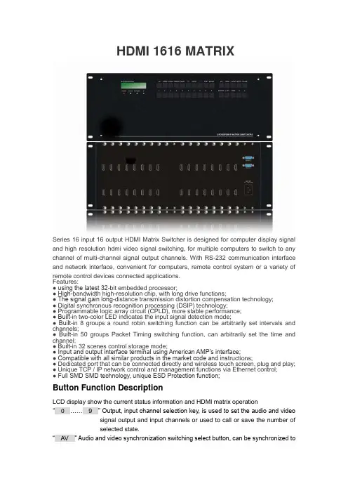
HDMI 1616 MATRIXSeries 16 input 16 output HDMI Matrix Switcher is designed for computer display signal and high resolution hdmi video signal switching, for multiple computers to switch to any channel of multi-channel signal output channels. With RS-232 communication interface and network interface, convenient for computers, remote control system or a variety of remote control devices connected applications.Features:● using the latest 32-bit embedded processor;● High-bandwidth high-resolution chip, with long drive functions;● The signal gain long-distance transmission distortion compensation technology;● Digital synchronous recognition processing (DSIP) technology;● Programmable logic array circuit (CPLD), more stable performance;● Built-in two-color LED indicates the input signal detection mode;● Built-in 8 groups a round robin switching function can be arbitrarily set intervals and channels;● Built-in 50 groups Packet Timing switching function, can arbitrarily set the time and channel;● Built-in 32 scenes control storage mode;● Input and output interface terminal using American AMP's interface;● Compatible with all similar products in the market code and ins tructions;● Dedicated port that can be connected directly and wireless touch screen, plug and play;● Unique TCP / IP network control and management functions via Ethernet control;● Full SMD SMD technology, unique ESD Protection function;Button Function DescriptionLCD display show the current status information and HDMI matrix operation“0……9” Output, input channel selection key, is used to set the audio and video signal output and input channels or used to call or save the number ofselected state.“AV” Audio and video synchronization switching select button, can be synchronized tothe same channel of audio and video signal switching to the same outputchannel.- case 1: Press the button according to the "3", "AV", "6", "END","ENTER" said it will 3 audio and video synchronization signalswitch to 6 road output channel.“VIDEO”Video switch separately select button, can alone will be a chann el of video signal switching to another output channel.- case 1: the order in accordance with the "3", "VIDEO" and "1","0","END", "ENTER" said it will 3 independent VIDEO signalswitching to the 10th output channel.“AUDIO” Audio switch select button, but alone will be a independent of audio signal independent switch to a different output channel.- case 1: the order in accordance with the "1", "2" and "AUDIO","6","END", "ENTER" said to AUDIO signal independent switch to6 road 12 output channel.“ / ” Command intervals button, when the output channel is not a single channel, used for interval output channel port number.- case 1:Press button according to the "1", "AV", "2", "/", "1", "3", "/","6","END", "ENTER" said it would 1 audio and video signals atthe same time to switch to the second road, 13, 6 outputchannel.“END” Stop button, is used to end a select command.。
一、高清混合矩阵切换器(HDMI)原理矩阵的接口分为信号输入\输出接口,INPUT 部分为信号输入端,OUTPUT部分为信号输出端。
将信号源(如电脑、DVD机)设备的输出端接入矩阵输入端(INPUT),将矩阵输出端(OUTPUT)接至信号使用设备(如投影机、电视机)的输入接口。
主要按键1、Cancel键(取消键)在任何页面按“Cancel”都会回到待机画面状态。
2、ENTER键(确认键)相当于电脑的回车键,表示进入、确认3、VIDEO键(视频键)视频切换模式按钮4、AUDIO键(音频键)音频切换模式按钮5、A V键(音视频键)音视频同步切换模式按钮6、ALL:所有按钮,输入端口对所有输出端口时使用7、SWITCH切换键按Switch 键进入切换菜单,多次按此键,可以在VIDEO、AUDIO、A V模式切换。
7.1 A V SWITCH,音视频同时切换。
在这个状态下,用数字键输入输入通道号和输出通道号,然后按OK(Enter)键,实现切换7.2 VIDEO SWITCH,只切换视频,而不切换音频7.3 AUDIO SWITCH,只切换音频,而不切换视频7.4 A V TO ALL,把某路输入音视频同时切换到所有输出7.5 A V N TO N,进行一对一切换,1到1,2到2,3到3,······n到n其它按键(选择了解)POWER:电源指示灯RUN:矩阵工作指示灯IR:红外遥控接收头窗口SA VE:模式保存按钮MODE:模式调用按钮ALL:所有按钮,输入端口对所有输出端口时使用F1:自定义键(默认一一对应)FUN键(功能键):进入功能菜单,多次按此键可以在对应功能间切换。
操作步骤1、通过HDMI接口,将笔记本(信号源)与一号桌插相连。
注:一号桌插对应HDMI矩阵的一号输入口。
2、在矩阵待机状态下两次按SWITCH切换键,出现以下界面:3、在问号处键入数字1,因为步骤1中选择的是1号桌插。

HDMI 3D 矩阵切换器用户手册V1.2版广州市天誉创高电子科技有限公司CREATOR CORPORATION(CHINA )符号的意义■安全指示使用说明书和设备上都使用了符号,指出可能对用户或他人造成的伤害以及财产受损的风险,以便您能够安全、正确地使用设备。
指示及其含义如下,请确保在阅读说明书之前正确理解这些指示。
此为A级产品,在生活环境中,该产品可能会造成无线电干扰。
在这种情况下,可能需要用户对干扰采取切实可行的措施。
提醒使用者设备内出现的未绝缘危险电压可能会导致人遭受电击。
CE认证表示此产品已经达到了欧盟指令规定的安全要求,用户可放心使用。
SGS认证表示此产品已经达到了全球最大的瑞士通用公证行的质检标准。
本产品通过ISO9001国际质量认证(认证机构:德国莱茵TUV)。
警告:为了避免电击,请不要打开机盖,也不要将无用的部分放在机箱内。
请与有资格的服务人员联系。
■一般信息指示列示了可能导致操作或设置不成功的内容及一些需要注意的相关信息。
指明可以找到相关主题详细资讯的所在页。
重要说明警告为确保设备可靠使用及人员的安全,请在安装、使用和维护时,请遵守以下事项:安装时的注意事项◆请勿在下列场所使用本产品:有灰尘、油烟、导电性尘埃、腐蚀性气体、可燃性气体的场所;暴露于高温、结露、风雨的场合;有振动、冲击的场合。
电击、火灾、误操作也会导致产品损坏和恶化;◆在进行螺丝孔加工和接线时,不要使金属屑和电线头掉入控制器的通风孔内,这有可能引起火灾、故障、误操作;◆产品在安装工作结束,需要保证通风面上没有异物,包括防尘纸等包装物品,否则可能导致运行时散热不畅,引起火灾、故障、误操作;◆避免带电状态进行接线、插拔电缆插头,否则容易导致电击,或导致电路损坏;◆安装和接线必须牢固可靠,接触不良可能导致误操作;◆对于在干扰严重的应用场合,高频信号的输入或输出电缆应选用屏蔽电缆,以提高系统的抗干扰性能。
布线时的注意事项◆必须将外部电源全部切断后,才能进行安装、接线等操作,否则可能引起触电或设备损坏;◆本产品通过电源线的接地导线接地,为避免电击,必须将接地导线与大地相连,在对本产品的输入端或输出端进行连接之前,请务必将本产品正确接地;◆在安装布线完毕,立即清除异物,通电前请盖好产品的端子盖板,避免引起触电。

HDMI 4x4 Matrix Switch, 4K/60Operation Manual500444SAFETY PRECAUTIONSTo insure the best performance from the product, please read all instructions carefully before using the device. Save this manual for future reference.●Follow basic safety precautions to reduce the risk of fire, electrical shock andinjury.●Do not dismantle the housing or modify the module. It may result in electricalshock or burn.●Do not open or remove the housing of the device as you may be exposed todangerous voltage or other hazards.●To prevent fire or shock hazard, do not expose the unit to rain, moisture anddo not install this product near water. Keep the product away from liquids.●Spillage into the housing may result in fire, electrical shock, or equipmentdamage. If an object or liquid falls or spills on to the housing, unplug themodule immediately.●Do not use liquid or aerosol cleaners to clean this unit. Always unplug thepower to the device before cleaning.●Using supplies or parts not meeting the products’ spec ifications may causedamage, deterioration or malfunction.●Refer all servicing to qualified service personnel.●Install the device in a place with adequate ventilation to avoid damage causedby overheat.●Unplug the power when left unused for a long period of time.●Information on disposal of devices: do not burn or mix with general householdwaste, please treat them as normal electrical waste.NOTICE: Please read this manual carefully before using this product.Table of Contents1.Introduction (4)2. Features (5)3. Package Contents (5)4. Specifications (6)5. Panels Description and Unit Installation (7)5.1 Front Panel (7)5.2 Rear Panel (7)5.3 Matrix Switch Installation (8)5.4 Management Options (9)6. Front Panel Control (10)6.1 Navigating the Menu (10)6.2 Menu – Scaler Function per Port (10)6.3 Menu – Select EDID per Port (11)6.4 Menu – View IP Config (13)6.5 Connectivity Operation (14)7. IR Handheld Remote Control (15)8. RS232 Remote Control (16)9. Telnet Remote Control (19)Regulatory Compliance (20)1.IntroductionThe HDMI 4x4 Matrix Switch, 4K/60 (500444) connects four HDMI sources to four displays. The matrix supports 1080p @ 60Hz up to 4K @ 60Hz (4:4:4), 3D formats and EDID management. It works with Blu-Ray players, Set-Top Boxes, Media Players, Home Theater PCs, and Game Consoles that connect to an HDMI display. Any source may be connected to any display by selecting it via the supplied IR Remote Control, RS-232, TCP/IP or by using the selection buttons on the front panel.2. Features●HDMI 2.0 supporting up to a 4K resolution at 60Hz (4:4:4) and 3Dformats.●Deep Color supporting 10 & 12-bit.●Supports LPCM 7.1CH, Dolby TrueHD, Dolby Digital Plus, DolbyAtmos, DTS-HD Master Audio and DTS:X●Allows any source to be displayed on multiple displays at the sametime.●Allows any HDMI display to view any HDMI source at any time.●Each of the 4-input ports support independent EDID.●Supports Digital Audio output.●May be controlled via IP, RS-232, Handheld IR Remote and FrontPanel Buttons.●Front-panel LCD display for status feedback.●HDMI connectors with Locking nuts.●Locking 2.1mm power connector.3. Package Contents●One (1) HDMI 4x4 Matrix Switch, 4K/60●One (1) 12V/5A DC power adapter●One (1) Operation Manual●One (1) Handheld IR Remote●Two (2) Mounting ears●One (1) IR Sensor cableNote:Please confirm if the product and the accessories are all included. If not, please contact the location at which you purchased the unit.4. Specifications5. Panel Description and Unit Installation 5.1 Front Panel5.2 Rear Panel5.3 Matrix Switch Installation1.Mount the Matrix Switch in its final location, such as on a 19 rack, withthe supplied mounting brackets.2.Make sure all equipment is powered off. Insert and extract cables carefullywith the power SWITCHED OFF. Connecting and disconnecting while the unit is powered can result in damage to the equipment.3.Connect up to 4 sources such as a Blu-Ray player, a media player, a gameconsole, an A/V Receiver, a Cable or Satellite Receiver, etc., to the HDMI inputs on the unit. Note that high-quality HDMI cables are recommended.Respect cable distance specifications.4.Connect the HDMI output ports to high-definition displays such as anHDTV or an HD projector that uses HDMI inputs. Note that high-qualityHDMI cables are recommended. Respect cable distance specifications. 5.For power, plug in the Matrix Switch power jack first, and then plug in thepower supply to the wall. The unit automatically turns on, and is read foroperation.6.Power on each device in the same sequence. At this point each displayconnected should display the assigned source (input 1 at default whenpowered on initially), scroll through each of the sources on each display to ensure everything is in working order. Use the front panel display andkeypad, or included IR remote to test the switching function. If a display is having difficulty receiving the HDMI signal, access the display’s menuand adjust the resolution (lowest to highest until signal is displayed).Please note that a 24 Hz vertical refresh rate may work better than 60 Hz or higher.5.4 Management OptionsThe Matrix Switch may be operated via the front panel display & keypad, by IR and by IP.See the “Local Switch Control” chapter for managing the unit via the front panel. Refer to the Handheld Remote Control chapter to manage the Matrix Switch via the supplied Handheld IR Remote. See the RS232 Control chapter to manage the unit remotely via RS232.6. Front Panel Control6.1 Navigating the MenuThe menu is in an idle state by default, and may be activated via the front panel display and keypad by pressing the [Menu] button twice. The first press illuminates the LCD Display and summarizes the connection status, plus the device is ready for connection changes. The second press of the [Menu] button brings up the menu selection.Note:1.If no buttons are pressed for several seconds, then the menu will return tothe idle state.2.The Matrix Switch may also be managed remotely, which is described inthe Remote Control chapter.Navigate through the menu by pressing the [UP] or [Down] buttons, and use the [Enter] button to select one of the menu headings. Once inside one of the menu headings, pressing the [Menu] button again returns the system to the main menu list.6.2 Menu – Scaler Function per PortNavigate to the “Set Out Scaler” heading on the Menu, and press the [Enter] button to select one of the scaler settings. Use the [Up] or [Down] buttons to cycle through the Scaler options. Press the [Enter] button to select one of the scalers, and then press the [Up] or [Down] buttons to select which output port (from 1 to 4, or ALL) to apply the scaling, and press [Enter] to set it. Each output port can have its own scaling setting, independent of any other output.6.3 Menu – Select EDID per PortNavigate to the “Select EDID” heading on the Menu, and press the [Enter] button to select one of the many EDID settings (see the table below for EDID setting options). Use the [Up] or [Down] buttons to cycle through the EDID options. Press the [Enter] button to select one of the EDID settings, and then press the [Up] or [Down] buttons to select which input port (from 1 to 4, or ALL) to apply the EDID setting, and press [Enter] to set it. Each input port can have its own EDID setting, independent of any other input.By default the matrix is set to a 1080P EDID, this is to maximize plug and play capability. When using 4K sources, you will want to define a 4K EDID on the given input (or read the EDID from the display).Note:1.What is an EDID, and what is it used for?Under normal circumstances, the source device will require informationabout a connected device/display to assess what resolutions and featuresare available. The source can then configure its output to send onlyresolutions and features that are compatible with the attacheddevice/display. This information is called EDID (Extended DisplayInformation Data).Also, a source device can only accept and read one EDID from aconnected device/display. Likewise, the source can only output oneresolution for use by a connected device/display.2.Why is the EDID so important for the HDMI Matrix?The Matrix is a complex piece of technology that replicates and switchesbetween multiple inputs and outputs. Each connected source device willrequire one EDID to read. EDID management is carefully handled by theHDMI Matrix to provide a single EDID for each source to read.3.What options do I have to manage the EDID in the HDMI Matrix?First, it is important to note that each source device can only output onevideo/audio signal type. This includes resolutions and timings. Whenmultiple devices/displays are used, such as with the HDMI Matrix, it isimportant to use devices/displays that have similar or compatibleresolutions/features. This will ensure that the single video/audio signalproduced by the source device is accepted by all of the connected outputdevices/displays. The user has the option, through the EDID managementwindow, to choose how the unit will manage the EDID from multipleHDMI devices/displays. Therefore the user has some control over theresolutions/features that the source devices will output. The HDMIMatrix has multiple EDID management modes that will control how theEDID information from multiple devices/displays are combined, ignored,and routed.6.4 Menu – View IP ConfigNavigate to the “View IP Config” heading on the Menu, and press the [Enter] button to select it. Use the [Up] or [Down] buttons to cycle through the available IP parameters to view.The “View IP Config” menu has the following IP param eters to view:In order to prevent potential IP problems, most IP settings must be managed in the Free PC Software or via the RS-232 commands.Cascade Mode:Cascade mode can only be turned On or Off via RS232. When CascadeMode is turned on, the signal is passed from the switch without readingthe EDID or Hot Plug. Many issues can be resolved in the field with this mode, including:∙Invalid or incorrect EDID coming from display (this may happen more often than one would think).∙When you want to manage EDID in a device further down the chain (such as an AVR or Distribution Amp).∙When running one or more output into additional peripheralsbefore the display.We recommend you ONL Y use cascade mode if you have exhausted all other trouble shooting options. To toggle Cascade Mode On or Off, use the appropriate RS232 command (see the RS232 command table).6.5 Connectivity OperationWhen making a connection, begin by pressing the Output port (1 to 4, or ALL), then press the Input port (1 to 4, or ALL) to be connected.Note:An Input port may be connected to more than one output port.7. IR Handheld Remote ControlThe HDMI routing of the matrix can also becontrolled by using the IR handheld remotecontrol supplied with the product.The number labels on the left represent the Outputport numbers.Each Output port has a set of Left and RightArrow buttons, which are used to select the Inputport to connect with. For example, the LeftArrow button decrements to the next lower Inputport, and the Right Arrow increments to the nexthigher Input port.Number 1 to 4 are for Output port 1 to Output port 4.IR Sensor NoteThe unit supports an IR sensor on the front panel so that it may be managed via the IR Handheld Remote. However an IR Sensor may also be connected to the IR Ext port on the rear of the unit, in order to extend the IR sensor to a more convenient location for improving line-of-site with the IR handheld remote.8. RS232 Remote ControlThe Matrix Switch may be managed via RS232 commands. Connect an RS232 cable between the command terminal (which may be a PC running terminal emulation software) and the Matrix Switch. MuxLab also provides at no charge a control software package that may be downloaded from the MuxLab website, to be used to send RS232 commands to the Matrix Switch.When connecting the terminal to the Matrix switch, make sure the RS232 cable has the correct termination on both ends for the devices being connected. Note that the Matrix Switch comes with a 9 Pin D-Sub connector with female sockets (the cable will require a 9-Pin D-Sub connector with male pins).For correct communication, set the RS232 parameters to the following settings: ∙57600 Baud∙8 Data Bits∙ 1 Stop Bit∙No Parity9. Telnet Remote ControlThe RS232 commands in the previous section, may also be used via Telnet, allowing the Matrix Switch to be managed over a TCP/IP network. Open a Telnet session, use port 23, and make use of the RS232 commands above.Regulatory ComplianceDisclaimerInformation in this document is subject to change without notice. The manufacturer does not make any representations or warranties (implied or otherwise) regarding the accuracy and completeness of this document and shall in no event be liable for any loss of profit or any other commercial damage, including but not limited to special, incidental, consequential, or other damages.No part of this document may be reproduced or transmitted in any form by any means, electronic or mechanical, including photocopying, recording or information recording and retrieval systems without the express written permission of the manufacturer.All brand names and product names used in this document are trademarks, or registered trademarks of their respective holders.8495 Dalton Road, Mount Royal, Quebec, Canada. H4T 1V5Tel: (514) 905-0588 Fax: (514) 905-0589Toll Free (North America): (877) 689-5228E-mail:********************URL:。

API COMMAND SET v1.0.01.Overview (3)1.1.Before You Begin (3)2.RS-232 Port Communication (3)2.1.RS-232 Port Configuration (3)2.2.RS-232 Communication Format (3)mand Structure (3)mand Table (3)4.1.Input and Output Switching (3)4.2.CEC Control (4)4.3.EDID Configuration (5)4.4.System Info (6)4.5.Audio Mute (7)5.SUPPORT (7)1.The following information will guide the installer through the set-up and programming for controlling a B-660-MTRX-4X2 via RS-232 serial and Telnet. Read through these instructions thoroughly before starting the process to ensure that all parameters and commands are correct.ly executed.1.1.Before You BeginEnsure that the following item are on hand before proceeding.B-660-MTRX-4X2 Matrix Switcher with Latest Firmware Installed ...................................................................RS-232 Serial or IP Controller .....................................................................................................................................Documentation for the RS-232 Control System .....................................................................................................Cables and Adapters to Connect to the Control System .......................................................................................List of Functions to Program into the Controller ....................................................................................................2.2.1.RS-232 Port ConfigurationThis matrix uses 3-pin terminal connector with defined pins for RS-232 serial communication, this allows for using standard category or other standard cable to connect the matrix to a controller or PC. If using a pre-built adapter ensure that the pins match Diagram 1 on the matrix side and the pins on the controlling device for the other side.Refer to the documentation for the control device being used for proper construction of the cable or selection of a port adapter.Diagram 1: RS-232 Port Pinout2.2.RS-232 Communication FormatThe following settings are default to the matrix and must be used when connecting.mand StructureCommands for this matrix are structured in a [Command] [Parameter(s)]<CR>LF> format. All commands and responses are case sensitive and should be entered as defined in the commands listed below.Syntax: [Command] [Parameter]<CR>LF>Example Command for selecting Input 1 (source) on Output 2 (display):SET SW in1 out2<CR>LF>mand Table1Switch Input for Output Command:SET SW in out <CR><LF> Return:SW in out <CR><LF> Parameter:in = {in1, in2, in3, in4}; out = {out1,out2};Description:SW is short for Switch Switch one input source forone output sink Command:SET SW in1 out2<CR><LF>Return:SW in1 out2<CR><LF>Description: Switch input 1 for hdmi output 22Get which input mapping to the indicate Output Command:GET MP out<CR><LF> Return:Mp in out<CR><LF>Parameter:in = {in1, in2, in3, in4}; out = {out1,out2};Description:MP is short for mapping Get which input mapping tothe indicate OutputCommand: GET MPout1<CR><LF> Return:MP in1 out1<CR><LF> Description:Get which input mapping to output 14Get which output mapping to all input Command: GET MP all<CR><LF> Return: MP in out<CR><LF> MP in out<CR><LF> ......Parameter: in = {in1, in2, in3, in4}; all = {all}; Description: in - none means power down outputMP is short for mapping Get which output mapping to all inputCommand: GET MP all <CR><LF>Return: MP in1 out1<CR>... MP in2 out2<CR><LF> Description: Get whichoutput mapping to all input6Set CEC AUTO POWER ON/OFFCommand: SET AUTOCEC_FN out prm <CR><LF> Return: AUTOCEC_FN out prm <CR><LF> Parameter: prm = {on, off} out = {out1, out2}; Description: Set sink auto power Function ON or OFF Command: SET AUTOCEC_FNout1 on <CR><LF> Return: AUTOCEC_FN out1on <CR><LF> Description: Set sink hdmi output 1 auto powerON7Get CEC AUTO POWER ON/OFF StatusCommand:GET AUTOCEC_FN out <CR><LF>Return: AUTOCEC_FN out prm <CR><LF>Parameter: prm = {on, off} out = {out1, out2}; Description:Get Sink auto power Function ON or OFF Status.Command:GET AUTOCEC_FN out1<CR><LF>Return:AUTOCEC_FN out1 onDescription:Get Sink auto power status, and the status is ON.8Set CEC POWER Delay TimeCommand: SET AUTOCEC_D out prm <CR><LF>Return: AUTOCEC_D out prm <CR><LF> Parameter: out = {out1,out2}; prm = {1,2,3…,}// according to the actual time counter,1 means 1 minute ,2 means 2 minutes ,Default wait time is 2 minutes, Max wait time is 30 minutes. Description: AUTOCEC_D is short for CEC auto Power DelayCommand: SET AUTOCEC_Dout1 2<CR><LF> Return: AUTOCEC_D out1 2<CR><LF> Description: when no active signal to hdmiout1, 2 minutes later, the unit will auto power off. 4.3. EDID ConfigurationIDX FunctionCommandExample10Set Input EDIDCommand: SET EDID in prm <CR><LF> Return: EDID in prm <CR><LF>Parameter: in = {in1, in2, in3, in4}; prm = {1 ~11} 1) RestoreDefaults; 2) Copy EDID from HDMI out1; 3) Copy EDID from HDMI out2; 4) 4K@60Hz 4:4:4, 2.0ch, with HDR; 5) 4K@60Hz 4:4:4, 5.1ch, with HDR; 6) 4K@60Hz 4:4:4, 7.1ch, with HDR; 7) 4K@30Hz 4:4:4, 2.0ch, with HDR and 4:2:0; 8) 4K@30Hz4:4:4, 7.1ch, with HDR and 4:2:0; 9) 1080P@60Hz, 2.0ch; 10) 1080P@60Hz, 5.1ch; 11) 1080P@60Hz, 7.1ch ; Description: Set Input EDIDCommand: SET EDID in1 4<CR><LF> Return: EDID in1 4<CR><LF> Description: Set in1EDID 4K@60Hz 4:4:4, 2.0ch, with HDR11Get All Input EDID status Command: GET EDID all <CR><LF>Return: EDID in prm <CR> EDID in prm <CR> EDID in prm <CR><LF> ......Parameter: in = {in1,in2,in3,in4}; prm = {1 ~11} 1) Restore Defaults; 2) Copy EDIDfrom HDMI out1; 3) Copy EDID from HDMI out2; 4) 4K@60Hz 4:4:4, 2.0ch, with HDR; 5) 4K@60Hz 4:4:4, 5.1ch, with HDR; 6) 4K@60Hz 4:4:4, 7.1ch, with HDR; 7)4K@30Hz 4:4:4, 2.0ch, with HDR and 4:2:0; 8) 4K@30Hz 4:4:4, 7.1ch, with HDRand 4:2:0; 9) 1080P@60Hz, 2.0ch; 10) 1080P@60Hz, 5.1ch; 11) 1080P@60Hz,7.1ch ;Description: Get all input EDID StatusCommand: GET EDID all <CR><LF> Return: EDID in1 1<CR> EDID in2 2<CR>Description: Get all input EDID Status12 Get one input EDID Status Command: GET EDID in <CR><LF> Return: EDID in prm <CR><LF>Parameter: in = {in1,in2,in3,in4}; prm = {1 ~11} 1) Restore Defaults; 2) Copy EDID from HDMI out1; 3) Copy EDID from HDMI out2; 4) 4K@60Hz 4:4:4, 2.0ch, with HDR; 5) 4K@60Hz 4:4:4, 5.1ch, with HDR; 6) 4K@60Hz 4:4:4, 7.1ch, with HDR; 7)4K@30Hz 4:4:4, 2.0ch, with HDR and 4:2:0; 8) 4K@30Hz 4:4:4, 7.1ch, with HDR and 4:2:0; 9) 1080P@60Hz, 2.0ch; 10) 1080P@60Hz, 5.1ch; 11) 1080P@60Hz, 7.1ch ; Description: Get one input EDID StatusCommand: GET EDIDin1<CR><LF> Return: EDID in14<CR><LF> Description: Get in1 edid status, and the status is4K@60Hz 4:4:4, 2.0ch, withHDR;14Get selected target firmware version Command: GET VER<CR><LF> Return: VERprm <CR><LF> Parameter: prm = {…}// accordingto actual firmware version Description: Getselected target firmware versionCommand: GET VER<CR><LF> Return:VER 1.0<CR><LF> Description: Get allmodule firmware version16 Get IR SystemCodeCommand: Get IR_SC <CR><LF> Return: IR_SCprm<CR><LF> Parameter: prm = {all, mode1,mode2}; mode1 = 0x00 mode2 = 0x4eDescription: G et IR System CodeCommand: Get IR_SC <CR><LF> Return:IR_SC mode1<CR><LF> Description: GetIR System code ,IR System code ismode 119 Get AudioOutputmute statuspcm<CR><LF> Parameter: pcm = {on, off};;//on meansmute; off means unmute out = {hdmiaudioout1,hdmiaudioout2, spdifaudioout1, spdifaudioout2,audioout1, audioout2, all}; Description: Get AudioOutput mute statusCommand: GET MUTEaudioout1<CR><LF> Return: MUTEaudioout1 pcm<CR><LF>Description: Get Audio Output mutestatus.5.SUPPORTNeed Help? Contact Tech Support!If you need further clarification, please call tech support at 800.838.5052, or email ******************. For other information, instructional videos, support documentation, or ideas, visit our website and view your item’s product page at .。
hdmi矩阵切换器使用方法_hdmi矩阵切换器操作方法安全知识1.请使用带保护地的单相三线制电源,并确保整个系统使用同一保护地。
不能使用无保护地的电源,电源线的接地脚不能破坏。
无完善的接地,容易造成信号干扰,不稳定,还可能因漏电引起人身事故。
2.需要进行设备移动或其他需要断电的工作时,要关断所有的电源,包括关断外部电源插座,拔掉电源3.非专业人士未经许可,请不要试图拆开设备机箱,不要私自维修,以免损坏内部精密部件,或发生意外事故或加重设备的损坏程度4.从设备上插.拔信号线时,设备需要断电,以免击穿电路。
带电插拔造成的损坏不在保修范围5.注意防潮防尘,环境温度不要过高或过低6.不要将过重物品压在机器上,以免损坏7.遇到问题,请先详细参阅本说明,如不能解决,请联系我们目录一.前言 (3)二.注意事项 (3)三.产品介绍 (3)3.1包装清单 (3)3.2主要功能 (4)3.3参数表 (5)3.4输入与输出接口 (6)3.5安装说明 (7)四.操作指南 (8)4.1 HDMI 1.3 4×4矩阵 (8)4.2 前面板控制方式 (8)4.3 红外遥控器控制方式 (9)4.4 4×4红外矩阵控制HDMI输入设备 (9)五 PC控制用户指南 (10)安装 (10)步骤 (10)如何控制矩阵 (10)1.General页 (10)2.Matrix control页 (12)前言:感谢您购买迈拓维矩HDMI 4进4出带延长功能高清视频矩阵,在使用本产品前,请仔细阅读此用户手册。
按照手册内的内容安装并使用本产品,已保证您的安全和避免产品损坏,谢谢!由于产品升级,此用户手册可能不定期进行更新,此手册用途仅为操作指导,我们对于手册的内容与建议不做担保。
注意事项:不宜在过热、过冷、多尘、潮湿环境下使用本产品。
请避免过硬物体划伤产品表面请避免产品从高处跌落,以免损坏产品硬件本产品不具备防水功能,请避免液体渗入产品内部请不要人为拆散、组装或者更改本产品硬件、软件。
T o reduce the risk of fire or electric shock, read and follow all instructions and warnings in this manual. Keep this manual for future reference.1. Do not expose this apparatus to rain or moisture. Do not expose this equipment to drippingor splashing, and ensure that no objects filled with liquids, such as vases, are placed on the equipment. Do not use this apparatus near water.2. Do not remove cover. No user serviceable parts inside.3. Clean only with a dry cloth.4. Do not block any ventilation openings. Install according to manufacturer’s instructions.5. Do not install near any heat sources such as radiators, heat registers, stoves or otherapparatus (including amplifiers) that produce heat.6. Do not override the safety purpose of the polarized or grounding plug. A polarized plug hastwo blades, one of which is wider than the other. A grounding plug has two matching blades and a third grounding prong. The wide blade or the third prong is provided for your safety. If the provided plug does not fit into your outlet, consult an electrician for replacement of the obsolete outlet.7. Protect the power cord from being walked on or pinched, particularly at the plug end andwhere the power cord is attached to the apparatus.8. Only use attachments and accessories specified by the manufacturer.9. Refer all servicing to qualified service personnel. Servicing is required when the apparatushas been damaged in any way, such as when the power supply cord or plug is damaged, liquid has been spilled on or objects have fallen into the apparatus, the apparatus hasbeen exposed to rain or moisture, the apparatus does not operate normally, or it has been dropped.10. T o completely disconnect this equipment from power, disconnect the power supply cordfrom the power outlet.The lightning flash with arrowhead symbol, within an equilateral triangle, is intended to alert the user to the presence of uninsulated dangerous voltage within the product’s enclosure that may be of sufficient magnitude to constitute a risk of electric shock to persons.The exclamation point within an equilateral triangle is intended to alert the user to the presence of important operating and maintenance (servicing) instructions in the literature accompanying the appliance.2This equipment has been tested and found to comply with the limits for a Class B digital device, pursuant to Part 15 of the FCC Rules. These limits are designed to provide reasonable protection against harmful interference in a residential installation. This equipment generates uses and can radiate radio frequency energy and, if not installed and used in accordance with the instructions, may cause harmful interference to radio communications. However, thereis no guarantee that interference will not occur in a particular installation. If this equipment does cause harmful interference to radio or television reception, which can be determined by turning the equipment off and on, the user is encouraged to try to correct the interference by one or more of the following measures:• Reorient or relocate the receiving antenna.• Increase the separation between the equipment and receiver.• Connect the equipment into an outlet on a circuit different from that to which the receiver is connected.• Consult the dealer or an experienced radio/TV technician for help.Changes or modifications not expressly approved by the party responsible for compliance could void the user’s authority to operate the equipment.31. Product Overview (5)2. Features (5)3. Package Contents (5)4. Device Layout (6)4.1. B-660-MTRX-4x2 Front Panel (6)4.2. B-660-MTRX-4x2 Rear Panel (7)5. Installation & Wiring (8)5.1. Installation (8)5.2. Wiring (8)6. IR Remote control (10)7. RS-232 Control (10)8. Specifications (11)8.1. Transmission Distance (11)9. Warranty (12)10. Support (12)4The B-660-MTRX-4x2 is a 4K HDR 4x2 HDMI Matrix Switcher and allows up to four Ultra High Definition 4K HDR or 1080p HD inputs to be independently routed to two Ultra HD displays.For HDMI output 1, there is a 3.5mm analog and SPDIF optical audio output allowing audio to be extracted from the HDMI source connected to output 1. For HDMI output 2, there’s a SPDIF optical audio output, which can come from the HDMI output 2 source or the HDMI ARC from the TV. This audio is controlled by a dip slider setting on the unit. Each output port supports independent scaling and can be 4K or 1080P, even if the source is the same. The B-660-MTRX-4x2 features a RS-232 port for third party control system connection and control.2.• Routes four HDMI sources to two 4K HDR Ultra HD displays• HDCP 2.2 compliant• Supports up to 4K Ultra HD and DCI resolutions(4096x2160@60Hz)• Each output supports scaling from 4K to 1080P independently• Analog and digital audio de-embedded from output 1• Digital audio de-embedded from HDMI output 2 or HDMI ARC from TV• Supports 12-bit Deep Color, 3D, Lip Sync and loss-less HD audio formats pass through • Multiple control options, include RS-232, IR and push button controlsNote: If the input source is active, whether display device is connected or not, the audio de-embedding port will output normally.3.• 1 x B-660-MTRX-4x2 Matrix• 1 x DC 5V Power Adapter with US Pins• 1 x IR Remote• 1 x Phoenix Male Connector (3.5 mm, 3 Pins)• 2 x Mounting Brackets (with Screws)• 2 x Drywall Screws• 4 x Rubber Feet• 1 x Power Cord Sticker• 1 x Installation Manual54.1.B-660-MTRX-4x2 Front Panel1. POWER LEDOn: The device is powered on.Off: The device is powered off.2. OUTPUT1 SWITCH BUTTONPress to cycle through the active sources that are connected and available for Output 1.3. OUTPUT1 INPUT (1-4) LEDsOn: The HDMI input is selected and active for Output 1.Off: The HDMI input is not selected nor active for Output 1.4. OUTPUT2 SWITCH BUTTONPress to cycle through the active sources that are connected and available for Output 2.5. OUTPUT2 INPUT (1-4) LEDOn: The HDMI input is selected and active for Output 2.Off: The HDMI input is not selected nor active for Output 2.6. IR SENSORReceives IR from handheld IR Remote, IR Emitter, or IR Flasher.64.2. B-660-MTRX-4x2 Rear Panel1. +5V DCConnect to the provided DC 5V power adapter.2. HDMI IN (1-4)Connect to HDMI sources such as Blu-ray player, Media Player, or PC.3. HDMI OUT1Connect to an HDMI display such as a TV, Flat Panel Display, or Projector.4. SPDIF OUTConnect to audio devices such as AV system for digital de-embedded audio from HDMI OUT1.5. AUDIO OUTConnect to audio device such as Amplifier for analog de-embedded audio from HDMI OUT1.6. HDMI OUT2Connect to an HDMI display such as a TV.7. SPDIF OUTConnect to audio devices such as AV system for digital de-embedded audio output from HDMI OUT2 or ARC audio output from the TV connected to HDMI OUT2.8. DIP SWITCHDe-embedded: SPDIF OUT outputs de-embedded audio from HDMI OUT2 source.ARC: SPDIF OUT outputs the ARC audio from the TV connected to HDMI OUT2.9. RS-232Connect to a control PC or control system for RS232 serial control.75.5.1. InstallationThe B-660-MTRX-4x2 can be placed on a solid and stable surface, installed on a standard equipment rack shelf, or mounted to a wall or distribution box. When installed on a rack shelf, wall, or distribution box we strongly recommend that the included mounting ears be used to secure the device. When installing on a solid surface the use of the mounting ears is optional. Steps to install the switch using the supplied mounting ears:1. Attach the installation bracket to the enclosure using the screws provided in the packageseparately.2. The bracket is attached to the enclosure as shown.3. Repeat steps 1-2 for the other side of the unit.4. Mount the switch on a solid surface, rack shelf, wall, or distribution box with the includedmounting screws by screwing the mounting ears to the surface you are mounting to.5.2. WiringWarnings:• Before beginning any wiring be sure to disconnect the power from all devices in the system.• During wiring gently connect and disconnect the cables.Steps for device wiring:1. Connect HDMI INConnect the HDMI sources (such as PC, Blu-ray player, Apple TV, 4K media player, etc) to the HDMI IN 1-4. Ensure you are using a high-quality HDMI cable capable of supplying the maximum resolution you require2. Connect HDMI OUTConnect the HDMI display device (such as a TV, projector, LED/LCD display or otherdisplay device) to the HDMI OUT. Ensure you are using a high-quality HDMI cable capable of supplying the maximum resolution you require.83. Connect SPDIF OUT and AUDIO OUT• RS232 control: Connect a control PC or control system to RS232 port of the Matrix.• IR control: The IR Remote provided is for controlling the Matrix through IR signal.5. Connect the DC 5V power cord provided.6. Power on all attached devices.9106.The Matrix can be controlled by the IR Remote provided by pointing it directly at the IR sensor on front panel. This allows for selecting inputs (source) for each output (display) as well as power On and Off for connected CEC-enabled displays.Note:• While the battery is installed it is isolated from the internal contacts via a plastic tab. Be sure to remove this tab before operating the remote.• While the remote contains Output 3 and 4 these have no function on this matrix.Display of Output 1Display of Output 1Assigning Inputs (sources) to Outputs (display):1. On the remote locate the output to assign an input to, these are in order vertically from top to bottom labeled in the middle of the remote.2. Press the desired Input # or use thePrevious Next available inputs.Virtual IR Code Supported by Default (Matrix Switching Code)11Advanced users may need to control the matrix through RS232 serial communication.Connect a control PC or control system to the RS232 port of the receiver. API command for RS232 control is available in the separate document “API Command Set_ B-660-MTRX-4x2”. A professional RS232 serial interface software (e.g. Serial Assist) may be needed as well.Before executing the API command through RS232 serial connection, please ensure RS232interface of the device and the control PC are configured correctly.RS-232 Port Connection Pin outR T GN XX D TXRX G RS-232PortConnected RS-232Device PinsTransmission Distance8.1.122-Year Limited WarrantyThis Binary product has a 2-Year limited warranty. This warranty includes parts and labor repairs on all components found to be defective in material or workmanship under normal conditions of use. This warranty shall not apply to products that have been abused, modified or disassembled. Products to be repaired under this warranty must be returned to SnapAV or a designated service center with prior notification and an assigned return authorization number (RA).10.Need Help? Contact T ech Support!If you need further clarification, please call tech support at 800.838.5052, or email support@ . For other information, instructional videos, support documentation, or ideas, visit our website and view your item’s product page at .13Rev: 200331-1719© 2020 Binary。
A tlonA2x2 HDMI™ Matrix Switch HDMI™ version 1.3AT-HDMI-22M1. Introduction (1)2. Features (1)3. Package Contents (1)4. Operation Controls and Functions (2)4.1 Front Panel (2)4.2 Rear Panel (3)4.3 Remote Control (3)4.4 RS-232 Protocol (4)4.4.1 Pin Definition (4)4.4.2 Commands (4)5. Specifications (5)5.1 General Specification (5)5.2 Support Resolution (5)6. Connection and Installation (5)7. Safety (6)8. Warranty (7)AT-HDMI-22M is a high performance HDMI™ Matrix with remote control. It offers you maxi-mum convenience in HDMI™ signal distribution when you have multiple HDMI™ sources and displays to connect together. Each of the two HDMI™ sources can be directed to any one of the two outputs, so two displays can show 2 identical or 2 different sources at the same time. AT-HDMI-22M provides a maximum of 4 possible connection scenarios between sources and displays.When HDMI™ signal progresses through AT-HDMI-22M, it is re-timed, level compensated, phase error corrected, and data jitter eliminated, so the output is a regenerated brand new1. HDMI 1.3, HDCP 1.1 and DVI 1.0 compliant.2. HDMI input is compensated, clock / phase adjusted, and jitter eliminated so the output is a well tuned standard HDMI signal.3. Input source LED indicators on each output select.4. Ideal for home theater integration, conference room and retail stores.5. Compatible with all HDMI sources and displays.6. Supports high resolution input/output:PC: VGA, SVGA, XGA, SXGA and UXGA (1600X1200) &HDTV: 480i, 576i, 480p, 576p, 1080i, and 1080p7. RS-232 control.8. IR remote control.1. AT-HDMI-22M HDMI Matrix2. 5VDC Power Supply Adaptor3. Operation Manual4.1. Front Panel1. Remote control sensor.2. Power Switch & LED Indicator:The LED will illuminate when the power is turned on.3. Input Select/Indicators (A):Press the “HDMI OUT A” button repeatedly to switch to your desired source, and the LED will illuminate to indicate which input source is being selected, and routed to HDMI A dis-play.4. Input Select/Indicators (B):Press the “HDMI OUT B” button repeatedly to switch to your desired source, and the LED will illuminate to indicate which input source is being selected, and routed to HDMI Bdisplay.4.2 Rear Panel4.3 Remote Control 1. IR IN Socket:Plug the IR extender sensor (optional) into the socket for IR extension control.2. RS-232 Communication Port:Connect to the COM port of your PC for the distant control over RS-232 channel.3. HDMI inputs 1 and 2:Connect to the HDMI output of your source equipment such as DVD player or set-top-box.4. HDMI outputs A and B:Connect each of these output ports to the HDMI input of an HDMI display.5. Power:Plug the 5VDC power supply into the unit and connect the adaptor to AC wall outlet.1. Power:Press the button to turn on/off the unit.2. Input Select for HDMI OUT A:Press 1 or 2 to select the desired input source for HDMI OUT A.3. Input Select for HDMI OUT B:Press 1 or 2 to select the desired input source for HDMI OUT B.4. Void buttons (No function.)4.4 RS-232 Protocol4.4.1 Pin Definition*RS-232 transmission format:Baud Rate: 9600 bpsData bit: 8 BitsParity: NoneStop Bit: 1 bit4.4.2 CommandsCOMMAND ACTIONP0Power Off (standby) P1Power On *ST System Status *VR Firmware VersionA1Output A select Input1 A2Output A select Input2 B1Output B select Input1 B2Output B select Input2DVDPS3HDTV HDTV5.1 General Specification* Frequency bandwidth: 2.25Gbps (single link)* HDMI ™ v1.3* Input/Output: 2-in to 2-out HDMI female ports * 5V DC power supply* Dimensions: 240 (W) x 165 (D) x 49 (H)mm * Weight: 3.1Kgs 5.2 Support Resolution INTPUT PC VGA, SVGA, XGA, SXGA, UXGATV480i, 480p, 576i, 576p, 720p, 1080i, 1080pOUTPUTPC VGA, SVGA, XGA, SXGA, UXGATV480i, 480p, 576i, 576p, 720p, 1080i, 1080pSafeguardsTo reduce the risk of electric shock, do not expose this product to rain or moisture.If the wall plug does not fit into your local power socket, hire an electrician to replace your obsolete socket.Do not modify the wall plug.Doing so will void the warranty and safety features.This equipment should be installed near the socket outlet and the device shouldbe easily accesible in case it requires disconnection.PrecautionsFCC Regulations state that any unauthorized changes or modifications to this equipment not expressly approved by the manufacturer could void theuser’s authority to operate this equipment.Operate this product using only the included external power supply. Use of other power supplies could impair performance, damage the product or cause fires.In the event of an electrostatic discharge, this device may automatically turn off. If this occurs, unplug the device, and plug it back in.Protect and route power cords so they will not be stepped on or pinched by anything placed on or against them. Be especially careful of plug-ins, or cord exit points from this product.Avoid excessive humidity, sudden temperature changes or temperature extremes.Keep this product away from wet locations such as bathtubs, sinks, laundries, wet basements and swimming pools.Use only accessories recommended by ATLONA to avoid fire, shock or other hazards.Unplug the product before cleaning. Usea damp cloth for cleaning. Do not use cleaning fluid or aerosols, which could enter the unit and cause damage, fire or electrical shock. Some substances may also mar the finish of the product.Never open or remove unit panels or make any adjustments not described in this manual. Attempting to do so could expose you to dangerous electrical shock or other hazards. It may also cause damage to your AT-HDMI-22M. Opening the product will void the warranty.Do not attempt to service the unit. Instead disconnect it and contact your Authorised ATLONA reseller or contact ATLONA directly.1. LIMITED WARRANTYAtlona Technologies warrants that (a) its products (the “Product”) will perform substantially in accordance with the accompanying written materials for a period of 3 YEARS from the date of receipt and (b) that the Product will be free from defects in materials and workmanship under normal use and service for a period of 3 years. In the event applicable law imposes any implied warranties, the implied warranty period is limited to 3 years from the date of receipt. Some jurisdictions do not allow such limitations on duration of an implied warranty, so the above limitation may not apply to Customer.2. CUSTOMER REMEDIESAtlona Technologies and its suppliers’ entire liability and Customer’s exclusive remedy shall be, at Atlona Technolo-gies’ option, either return of the price paid for the Product, or repair or replacement of the Product that does not meet this Limited Warranty and which is returned to Atlona Technologies with a copy of Customer’s receipt. This Limited Warranty is void if failure of the Product has resulted from accident, abuse, or misapplication. Any replacement Prod-uct will be warranted for the remainder of the original warranty period or 3 year, whichever is longer.3. NO OTHER WARRANTIESTO THE MAXIMUM EXTENT PERMITTED BY APPLICABLE LAW, ATLONA TECHNOLOGIES AND ITS SUPPLI-ERS DISCLAIM ALL OTHER WARRANTIES, EITHER EXPRESS OR IMPLIED, INCLUDING, BUT NOT LIMITED TO IMPLIED WARRANTIES OF MERCHANTABILITY AND FITNESS FOR A PARTICULAR PURPOSE, WITH REGARD TO THE PRODUCT AND ANY RELATED WRITTEN MATERIALS. THIS LIMITED WARRANTY GIVES CUSTOMER SPECIFIC LEGAL RIGHTS. CUSTOMER MAY HAVE OTHER RIGHTS DEPENDING ON THE JU-RISDICTION.4. NO LIABILITY FOR DAMAGESTO THE MAXIMUM EXTENT PERMITTED BY APPLICABLE LAW, IN NO EVENT SHALL ATLONA TECHNOLO-GIES OR ITS SUPPLIERS BE LIABLE FOR ANY DAMAGES WHATSOEVER (INCLUDING WITHOUT LIMITA-TION, SPECIAL, INCIDENTAL, CONSEQUENTIAL, OR INDIRECT DAMAGES FOR PERSONAL INJURY, LOSS OF BUSINESS PROFITS, BUSINESS INTERRUPTION, LOSS OF BUSINESS INFORMATION, OR ANY OTHER PECUNIARY LOSS) ARISING OUT OF THE USE OF OR INABILITY TO USE THIS PRODUCT, EVEN IF ATLONA TECHNOLOGIES HAS BEEN ADVISED OF THE POSSIBILITY OF SUCH DAMAGES. IN ANY CASE, ATLONA TECHNOLOGIES’ AND ITS SUPPLIERS’ ENTIRE LIABILITY UNDER ANY PROVISION OF THIS AGREEMENT SHALL BE LIMITED TO THE AMOUNT ACTUALLY PAID BY YOU FOR THE PRODUCT. BECAUSE SOME JU-RISDICTIONS DO NOT ALLOW THE EXCLUSION OR LIMITATION OF LIABILITY FOR CONSEQUENTIAL OR INCIDENTAL DAMAGES, THE ABOVE LIMITATION MAY NOT APPLY TO YOU.ATLONA2151 O’toole Ave, Ste DSan Jose CA 95131Toll Free: 1-877-536-3976International: 408-954-8782FAX: 408-954-8792Website: E-MAIL:***************。
A tlonA4 x 4 HDMI V1.3 Matrix SwitcherAT-HD-V44M1. Introduction (1)2. Application (1)3. Package Contents (1)4. System Requirement (1)5. Features (2)6. Installation (3)7. Front View (4)8. Remote Control (5)9. RS-232 Protocol (5)9.1 Commands (6)10. Connection and Installation (7)11. Specifications (8)12. Safety Information (9)13. Warranty (10)Thank you for purchasing Atlona’s 4 x 4 HDMI V1.3 Matrix Switcher. While HDMI products are getting more and more popular in the market people usually have more than one HDMI de-vices and sources in one place. The AT-HD-V44M provides the excellent solution for connecting all the devices and sources together for your convenience use, it also provides you a variety of choices of where to play your images with remote controller. Further, the AT-HD-V44M can transfer Deep Color video and bit stream digital audio with maximum performance and it sup-ports HDMI 1.3, HDCP 1.1 and DVI 1.0.Please follow this manual to begin enjoying the benefit of your Atlona HDMI 1.3 Matrix Switch-er. We suggest keeping it in a safe place for future reference.• High performance Atlona HDMI 1.3 Matrix Switcher with 4 (four) input and 4 (four) output with remote control for you to link with your favor HDMI devices to enjoy movies, music, or games at once.• Each of the four HDMI sources can be directed to any two of HDMI displays and or to all of the HDMI display.• When HDMI signal progresses through the system, it is re-timed, and level-compensated.• Define HDCP, HDMI and DVI source. The LED light will light up to define the input source’s format.• Switchable EDID function for choosing the native resolution to display.• 4 by 4 V1.3 HDMI Matrix Unit. (AT-HD-V44M)• Remote Control (with Battery)• IR Receiver• Power Cord• 5V DC power supply adaptor.• Operation Manual.HDMI input device(s) and HDMI output device(s).• HDMI 1.3, HDCP 1.1 and DVI 1.0 compliant.• Supports digital video formats in Deep Color 12bit and new lossless compressed (Dolby True-HD, Dolby Digital Plus and DTS-HD Master Audio) digital audio.• The HDMI input is compensated, clock / phase adjusted, and jitter eliminated so the output is a brand new standard HDMI signal.• Supports input source LED indicators on each output select.• Compatible with all HDMI sources and displays.• Supports a wide range of PC and HDTV resolutions from VGA to UXGA and 480i to 1080p.• Supports RS-232 control.• Supports IR remote control and IR extender.• Dolby Digital, DTS digital audio transmission (32-192 kHz Fs sample rate).• Supports LPCM7.1 channels output from each independent HDMI ports.• HDMI cable distance test with 1080p/8bit resolution, the Input/Output source can run up to 15/15 meters. If 1080p/12bit the Input/Output source can run up to 15/6 meters.1 EDID Control Switcher: Default factory setting is TV, leave as it is when the displays are working properly. Switch to STD to use build-in EDID Detail capability in Note.2 RS-232 communication port: Connect the COM port of your PC for the distant control over RS-232 channel. Detail specification in section 9.3 HDMI outputs: Connect each of these output ports to the HDMI display(s).4 HDMI inputs: Connect input ports to the HDMI or DVI output of your source equipment such as DVD player or set-top-box.5 Power: Plug the 5VDC power supply into the unit and connect the adaptor to AC wall outlet.6 IR extender.Note:1. EDID Control Switch: STD(INT) and TV(EXT), Default setting is TV2. When EDID is on TV: Leave as it is if display is properly, unit will detect the first HDMI output source’s EDID and record in the unit. If the first detected output source is DVI it will pass to next source, until the first HDMI been detected. The detection priority is HDMI v1.3 > HDMI v1.2 > DVI.3. When EDID is on STD: unit use build-in EDID Video Support->1080p 12bit(max) Audio Sup -port->PCM24. Your EDID selection will only activate when the unit is replugged and powered on.1345621 Remote control sensor.2 Power switch & LED Indicator: The LED will illuminate when the power is turned on.3 Input Select/Indicators (A): Press the HDMI out “A” button repeatedly to switch to your desired source and the LED will illuminate to indicate which input source is being selected and routed to HDMI A output. When an HDMI or DVI source is connected the LED light labeled “HDMI/DVI” will activate. If the source is HDCP encrypted, the LED light labeled “HDCP” will acti -vate.4 Input Select/Indicators (B): Press the HDMI out “B” button repeatedly to switch to your desired source and the LED will illuminate to indicate which input source is being selected and routed to HDMI B output. When an HDMI or DVI source is connected the LED light labeled “HDMI/DVI” will activate. If the source is HDCP encrypted, the LED light labeled “HDCP” will acti -vate.5 Input Select/Indicators (C): Press the HDMI out “C” button repeatedly to switch to your desired source and the LED will illuminate to indicate which input source is being selected and routed to HDMI C output. When an HDMI or DVI source is connected the LED light labeled “HDMI/DVI” will activate. If the source is HDCP encrypted, the LED light labeled “HDCP” will acti -vate.6 Input Select/Indicators (D): Press the HDMI out “D” button repeatedly to switch to your desired source and the LED will illuminate to indicate which input source is being selected and routed to HDMI D output. When an HDMI or DVI source is connected the LED light labeled “HDMI/DVI” will activate. If the source is HDCP encrypted, the LED light labeled “HDCP” will acti -vate.7 HDCP Source light: When the input source(s) have HDCP , unit will detect the code and send to output source(s).8 HDMI/DVI Source light: When the input source(s) is HDMI format, the LED light will light up.213456781. Power: Press the button to turn on/off the unit.2. Input Select for HDMI OUT A:Press 1, 2, 3 or 4 to select the desired input source for HDMI OUT A.3. Input Select for HDMI OUT B:Press 1, 2, 3 or 4 to select the desired input source for HDMI OUT B.4. Input Select for HDMI OUT C:Press 1, 2, 3 or 4 to select the desired input source for HDMI OUT C.5. Input Select for HDMI OUT D:Press 1, 2, 3 or 4 to select the desired input source for HDMI OUT D.Pin Definition12345COMMAND ACTIONPOWER 00Power Off (standby) POWER 01Power OnPORT 11Output A select Input1 PORT 12Output A select Input2 PORT 13Output A select Input3 PORT 14Output A select Input4 PORT 21Output B select Input1 PORT 22Output B select Input2 PORT 23Output B select Input3 PORT 24Output B select Input4 PORT 31Output C select Input1 PORT 32Output C select Input2 PORT 33Output C select Input3 PORT 34Output C select Input4 PORT 41Output D select Input1 PORT 42Output D select Input2 PORT 43Output D select Input3 PORT 44Output D select Input4HD TV HD TVSTB DVDBlu-rayRS-232computer control portPS3HD TVHD TVFrequency bandwidth 2.25Gbps (single link)Input ports 4 x HDMI female portsOutput ports 4 x HDMI female portsEDID Standard, TV/Moving Port 1HDMI Audio output PCM2, PCM5.1, PCM7.1, Dolby5.1, DTS5.1, DD+, D- TrueHD, DTS-HDHDMI Cable in1080p 8bit (15M), 1080p 12bit (15M)HDMI Cable out1080p 8bit (15M), 1080p 12bit (6M)Color Space RGB_24/36,YCbCr 4:4:4_24/36, YCbCr 4:2:2,xvyccIR YesDeep Color1080p 12bitHDMI Resolution480I~1080p 50/60, 1080p 24, VGA~UXGADVI Resolution480I~1080p 50/60, 1080p 24, VGA~UXGAPower Supply5VDC/5A (US/EU standards, CE/FCC/UL certified)Dimensions (mm)438(W) x 175(D) x 49(H)Weight(g)3100Chassis Material MetalSilk Skin Color BlackOperating Temperature Operating from 0°C ~ 40°CPower Consumption16.5W(Max)SafeguardsTo reduce the risk of electric shock, do not expose this product to rain or moisture.If the wall plug does not fit into your local power socket, hire an electrician to replace your obsolete socket.Do not modify the wall plug.Doing so will void the warranty and safety features.This equipment should be installed near the socket outlet and the device shouldbe easily accessible in case it requires disconnection.PrecautionsFCC Regulations state that any unauthorized changes or modifications to this equipment not expressly approved by the manufacturer could void theuser’s authority to operate this equipment.Operate this product using only the included external power supply. Use of other power supplies could impair performance, damage the product or cause fires.In the event of an electrostatic discharge, this device may automatically turn off. If this occurs, unplug the device, and plug it back in.Protect and route power cords so they will not be stepped on or pinched by anything placed on or against them. Be especially careful of plug-ins, or cord exit points from this product. Avoid excessive humidity, sudden temperature changes or temperature extremes.Keep this product away from wet locations such as bathtubs, sinks, laundries, wet basements and swimming pools.Use only accessories recommended by ATLONA to avoid fire, shock or other hazards.Unplug the product before cleaning. Usea damp cloth for cleaning. Do not use cleaning fluid or aerosols, which could enter the unit and cause damage, fire or electrical shock. Some substances may also mar the finish of the product.Never open or remove unit panels or make any adjustments not described in this manual. Attempting to do so could expose you to dangerous electrical shock or other hazards. It may also cause damage to your AT-HD-V44M. Opening the product will void the warranty.Do not attempt to service the unit. Instead disconnect it and contact your Authorized ATLONA reseller or contact ATLONA directly.1. LIMITED WARRANTYAtlona Technologies warrants that (a) its products (the “Product”) will perform substantially in accordance with the accompanying written materials for a period of 3 YEARS from the date of receipt and (b) that the Product will be free from defects in materials and workmanship under normal use and service for a period of 3 years. In the event applicable law imposes any implied warranties, the implied warranty period is limited to 3 years from the date of receipt. Some jurisdictions do not allow such limitations on duration of an implied warranty, so the above limitation may not apply to Customer.2. CUSTOMER REMEDIESAtlona Technologies and its suppliers’ entire liability and Customer’s exclusive remedy shall be, at Atlona Technolo-gies’ option, either return of the price paid for the Product, or repair or replacement of the Product that does not meet this Limited Warranty and which is returned to Atlona Technologies with a copy of Customer’s receipt. This Limited Warranty is void if failure of the Product has resulted from accident, abuse, or misapplication. Any replacement Prod-uct will be warranted for the remainder of the original warranty period or 3 year, whichever is longer.3. NO OTHER WARRANTIESTO THE MAXIMUM EXTENT PERMITTED BY APPLICABLE LAW, ATLONA TECHNOLOGIES AND ITS SUPPLI-ERS DISCLAIM ALL OTHER WARRANTIES, EITHER EXPRESS OR IMPLIED, INCLUDING, BUT NOT LIMITED TO IMPLIED WARRANTIES OF MERCHANTABILITY AND FITNESS FOR A PARTICULAR PURPOSE, WITH REGARD TO THE PRODUCT AND ANY RELATED WRITTEN MATERIALS. THIS LIMITED WARRANTY GIVES CUSTOMER SPECIFIC LEGAL RIGHTS. CUSTOMER MAY HAVE OTHER RIGHTS DEPENDING ON THE JU-RISDICTION.4. NO LIABILITY FOR DAMAGESTO THE MAXIMUM EXTENT PERMITTED BY APPLICABLE LAW, IN NO EVENT SHALL ATLONA TECHNOLO-GIES OR ITS SUPPLIERS BE LIABLE FOR ANY DAMAGES WHATSOEVER (INCLUDING WITHOUT LIMITA-TION, SPECIAL, INCIDENTAL, CONSEQUENTIAL, OR INDIRECT DAMAGES FOR PERSONAL INJURY, LOSS OF BUSINESS PROFITS, BUSINESS INTERRUPTION, LOSS OF BUSINESS INFORMATION, OR ANY OTHER PECUNIARY LOSS) ARISING OUT OF THE USE OF OR INABILITY TO USE THIS PRODUCT, EVEN IF ATLONA TECHNOLOGIES HAS BEEN ADVISED OF THE POSSIBILITY OF SUCH DAMAGES. IN ANY CASE, ATLONA TECHNOLOGIES’ AND ITS SUPPLIERS’ ENTIRE LIABILITY UNDER ANY PROVISION OF THIS AGREEMENT SHALL BE LIMITED TO THE AMOUNT ACTUALLY PAID BY YOU FOR THE PRODUCT. BECAUSE SOME JU-RISDICTIONS DO NOT ALLOW THE EXCLUSION OR LIMITATION OF LIABILITY FOR CONSEQUENTIAL OR INCIDENTAL DAMAGES, THE ABOVE LIMITATION MAY NOT APPLY TO YOU.ATLONA2151 O’toole Ave, Ste DSan Jose CA 95131Toll Free: 1-877-536-3976International: 408-954-8782FAX: 408-954-8792Website: E-MAIL:***************。
HDMI Matrix 4 x 2Switch/Splitter Matrix with 4 Inputs, 2 Outputs, EDID, Video Bandwidth Amplifier and RemotePart No.: 207409Easily connect four HDMI sources to two displays.The Manhattan HDMI Matrix 4 x 2 gives you the option of connecting as many as four HDMI video sources — including gaming consoles, Blu-ray players, satellite receivers, digital recorders, set-top boxes and other devices — to one or two high-definition,ultra-high-definition (4K) or 3-D high-definition displays, as well as Deep Color HD projectors.Flexible Solution for Many HD ApplicationsPerfect for a variety of home or commercial applications, the HDMI Matrix has both manual selection switches and a convenient IR remote control so you can quickly select or switch between HDMI sources and displays. Additionally, an EDID control switch allows you to select the proper signal format for each display.Best Possible Image QualityThe Manhattan HDMI Matrix 4 x 2 is HDMI and HDCP 1.4a compliant, and delivers a stunningly clean, crisp and vivid picture up to 4K resolution on one or two displays thanks to an integrated video bandwidth amplifier. Additionally, it supports HD-quality 3-D video, as well as LPCM, DTS and Dolby TrueHD audio.Features:Share up to 4 HDMI sources between 2 displaysSupports 4K resolution, as well as HD 3-D video and Deep Color (48-bits/pixel)Integrated video bandwidth amplifier4K resolution, 3-D, Deep ColorRemote contol offers easy and convenient display/source selectionWorks with Playstation and Xbox game systems, Blu-ray players, set-top boxes,satellite receivers and moreFully HDCP compliantSupports LPCM, DTS Digital, DTS-HD Master Audio and Dolby TrueHD audioSupports 3-D video and Deep Color up to 48-bits per pixelEDID signal formatting, plug-and-play installationGold-plated contacts for corrosion-free connectionsThree-Year WarrantySpecifications:Standards and Certifications• HDMI 1.4• HDCP 1.4a• CE• FCC• RoHS2Connections• HDMI female (output) (2)• HDMI female (input) (4)• DC 5V portSignal Input/Output• Input video signal: 400 – 600 mV• Input DDC signal: 5 V p-p (TTL)• Maximum single-link range: 3 Gbps and 4K resolution • Output video: HDMI 1.4, HDCP 1.4a• Frequency: 3 Gbps / 300 MHzVideo Resolutions• DTV/HDTV: 480i/480p/576i/576p/720p/1080i/1080p/4K Physical• Dimensions: 192 x 84 x 26 mm (7.6 x 3.3 x 1 in.)• Weight: 0.45 kg (0.99 lbs.)Package Contents• HDMI Matrix 4 x 2• Remote Control• Power Adapter• Instructions。
875223 User Manual TLS HDMI Matrix 4K 2x28 875223 HDMI Matrix 4K 2x2 Thank you for purchasing this product. For optimum performance and safety, please read these instructions carefully before connecting, operating or adjusting this product. Please keep this manual for future reference.SURGE PROTECTION DEVICE RECOMMENDEDThis product contains sensitive electrical components that may be damaged by electrical spikes, surges, electric shock, lightning strikes, etc. Use of surge protection systems is highly recommended in order to protect and extend the life of your equipment.Table of Contents1. Introduction (3)2. Features (3)3. Panel Descriptions (4)4. IR Remote Control (6)5. Application Diagram (7)6. Specifications (8)7. Package Contents (8)8. Maintenance (9)9. Warranty Policy (9)10. Limitations of Warranty (9)11. Exclusive Remedies (10)12. RMA Policy (11)TLS electronics GmbH Contact: *********************** 2875223 HDMI Matrix 4K 2x2TLS electronics GmbH Contact: ***********************3IntroductionTLS HDMI Matrix 4K 2x2 is a high-definition switch and supports 3D, 4K*2K, and can be used to switch between two sources to two devices. It can be used in teaching, training, conferencing etc.With IR remote control you can switch the TLS HDMI Matrix 4K 2x2 from the distance.FeaturesIn line with the version 1.4 specification, support resolution of 4K*2K, support 3D signalWith the build in memory function, boot can broadcast channel picture last timeCan automatically search for a signal channel broadcastSupport of remote control and manual switchingSupport 340 MHz / 3.4 Gbps single channel bandwidthSupport 14/30/36/48 bit Deep Color RGBSupport Blu-Ray DVD 24/50/60fs/HD-DVD/ xvYCCAudio format DTS-HD / Dolby-trueHD / LPCM7.1 / DTS / Dolby-AC3 / DSD / HD/ HBRWith TLS digital cables you can reach up to 25m on the input, up to 25m on the output HDCP compatible8 875223 HDMI Matrix 4K 2x2Panel DescriptionsFront Panel•IR – IR receiver•SW – switching button•Power LED•HDMI Output LED L2 – L1•HDMI Input LED A - BYou can toggle with the switching button through positions of the matrix switcher youTLS electronics GmbH Contact: *********************** 4875223 HDMI Matrix 4K 2x2TLS electronics GmbH Contact: ***********************5Rear panel• DC,5V – Input power supply• HDMI IN A –B• HDMI OUT 1 - 28 875223 HDMI Matrix 4K 2x2 TLS electronics GmbH Contact: ***********************6Remote ControlWith the IR remote control it is made easy to switch to all possible positions of the matrix switching:A1A2A12B1B2B12A1B2A2B1Auto, when you press the button AUTO, the matrix turns to automatic switch status, it switches from A12 B12 A1B2 A2B1 in every 10 seconds,875223 HDMI Matrix 4K 2x2TLS electronics GmbH Contact: ***********************7Application Diagram8 875223 HDMI Matrix 4K 2x2 TLS electronics GmbH Contact: *********************** 8SpecificationsBandwidth3.4 Gbps per color Video InputConnectors2x HDMI Type A, 19-pin, female Video OutputConnectors2x HDMI Type A, 19-pin, female Dimensions(W x D xH)180 mm x 65 mm x 42 mm, without feet Shipping Weight0.3KG OperatingTemperature32°F to 104°F (0°C to 40°C) StorageTemperature- 4°F to 140°F (- 20°C to 60°C) Power Supply5V/1A DCPackage Contents1.1x 875223 TLS HDMI 4K Matrix 2x2 2.1x 5V/1A Power Supply 3.1x IR remote control875223 HDMI Matrix 4K 2x2TLS electronics GmbH Contact: ***********************9MaintenanceClean this unit with a soft, dry cloth. Never use alcohol, paint thinner or benzene to clean this unit.Warranty PolicyTLS electronics products are warranted against defects in material and workmanship for three years from the date of shipment. During the warranty period, TLS electronics will, at its option, repair or replace products that prove to be defective. Repairs are warranted for the remainder of the original warranty or a 90 day extended warranty, whichever is longer.For equipment under warranty, the owner is responsible for freight to TLS electronics and all related customs, taxes, tariffs, insurance, etc. TLS electronics is responsible for the freight charges only for return of the equipment from the factory to the owner. TLS electronics will return the equipment by the same method as the equipment was sent to TLS electronics.All equipment returned for warranty repair must have a valid RMA number issued prior to return and be marked clearly on the return packaging. TLS electronics strongly recommends all equipment be returned in its original packaging.TLS electronics obligations under this warranty are limited to repair or replacement of failed parts, and the return shipment to the buyer of the repaired or replaced parts.Limitations of WarrantyThe warranty does not apply to any part of a product that has been installed, altered, repaired, or misused in any way that, in the opinion of TLS electronics, would affect the reliability or detracts from the performance of any part of the product, or is damaged as the result of use in a way or with equipment that had not been previously approved by TLS electronics.8 875223 HDMI Matrix 4K 2x2 The warranty does not apply to any product or parts thereof where the serial number or the serial number of any of its parts has been altered, defaced, or removed.The warranty does not cover damage or loss incurred in transportation of the product.The warranty does not cover replacement or repair necessitated by loss or damage from any cause beyond the control of TLS electronics, such as lightning or other natural and weather related events or wartime environments.The warranty does not cover any labor involved in the removal and / or reinstallation of warranted equipment or parts on site, or any labor required to diagnose the necessity for repair or replacement.The warranty excludes any responsibility by TLS electronics for incidental or consequential damages arising from the use of the equipment or products, or for any inability to use them either separate from or in combination with any other equipment or products.A fixed charge established for each product will be imposed for all equipment returned for warranty repair where TLS electronics cannot identify the cause of the reported failure.Exclusive RemediesTLS electronics’s warranty, as stated is in lieu of all other warranties, expressed, implied, or statutory, including those of merchantability and fitness for a particular purpose. The buyer shall pass on to any purchaser, lessee, or other user of TLS electronics products, the aforementioned warranty, and shall indemnify and hold harmless TLS electronics from any claims or liability of such purchaser, lessee, or user based upon allegations that the buyer, its agents, or employees have made additional warranties or representations as to product preference or use.TLS electronics GmbH Contact: *********************** 10875223 HDMI Matrix 4K 2x2The remedies provided herein are the buyer’s sole and exclusive remedies. TLS electronics shall not be liable for any direct, indirect, special, incidental, or consequential damages, whether based on contract, tort, or any other legal theory.RMA PolicyWhen returning product to TLS electronics for any reason, the customer shouldfill out the official RMA form to obtain a RMA number. Without the permission or approval, TLS electronics will be no responsible for any return. This can be initiated by emailing or calling your related sales. All requests are processedwithin 48 hours.Standard ReplacementFor customers that agree to return defective product to TLS electronics first, aStandard Replacement option is available.An RMA number must first be issued by sales. This RMA number will need to be referenced on the outside of the return shipment.Upon receipt of the defective product, TLS electronics will, at its discretion, either repair or replace the product and ship it out in the most expeditious manner possible. Subject to availability, the replacement product will be shipped on the business day following receipt of the defective product.In the event the product returned to TLS electronics has been discontinued (i.e. the product is no longer being manufactured by TLS electronics but is still under warranty), TLS electronics will, at its discretion, either repair or replace with recertified product.TLS electronics GmbH Contact: *********************** 118 875223 HDMI Matrix 4K 2x2 Once you have obtained an RMA numberAfter obtaining an RMA number from TLS electronics, you must send the product - freight prepaid - to TLS electronics. The TLS electronics RMA number must be prominently displayed on the outside of your package. If you send your product to TLS electronics without the RMA number prominently displayed on the outside of the package, it will be returned to you unopened.Please use a shipping company that can demonstrate proof of delivery. TLS electronics does not accept responsibility for any lost shipments unless proof of delivery to TLS electronics is provided.Please note:Product shipped to TLS electronics must be properly packaged to prevent loss or damage in transit.Shipping your RMA to TLS electronics using regular mailing envelopes is not acceptable, as they do not protect the product from damage during shipping. TLS electronics will not repair or replace a module that is shipped in such a way that the product is not properly protected.TLS electronics will not accept any product that has been damaged as a result of accident, abuse, misuse, natural or personal disaster, or any unauthorized disassemble, repair or modification.TLS electronics GmbH Contact: *********************** 12。
HDMI矩阵操作手册安全操作指南为确保设备可靠使用及人员的安全,在安装,使用和维修时,请遵守以下事项:1.系统接地。
系统必须有完善的接地,否则,不仅造成讯号干扰,不稳定或机械损坏,而且还可能因漏电引起人身事故;请使用标准的三线电源插座,其地线接地电阻应小于1Ω。
2.禁止改变原设计。
禁止对本产品的机械和电器设计更改或增添任何部件。
否则。
本公司对由此所带来的后果不负责任。
3.请勿使用两芯插头,确保设备的输入电源为220V50Hz的交流电。
4.机器内有220V高压部件,请勿打开机壳,以免触电。
5.不要将机器置于过冷或过热的地方。
6.设备电源在工作时会发热,因此要确保工作环境的良好通风。
以免温度过高而损坏机器。
7.阴雨潮湿天气或长时间不用时,应关闭设备电源总闸。
一、产品简介…………………………………………..……………….1.关于HDMI系列矩阵切换器………..…….2.HDMI矩阵连接示意图………………二、矩阵系统的安装………..…………………….1、矩阵与控制电脑的连接……………………………….……….三、前面板功能键…………………………..………………..……….1、切换指令……………………………………..…………….2、UP、Down状态查询指令……………………..………….3、SAVE存储指令…………………………………………….4、RECALL调用指令…………………………………...…….5、CANCEL键…………………………………………..…….四、矩阵控制软件…………………….……….….五、R S232通讯协议…………………………………………………产品简介:1.1关于HDMI系列矩阵切换器HDMI数字视频矩阵切换器是为了将计算机数字视频信号进行重新分配和组合的矩阵交换设备,该设备可将多路HDMI数字视频输入信号切换到多路输出通道的任意通道上去。
可广泛用于所有需要进行HDMI信号分配和组合的场合,应用领域涉及军工、多媒体教学、电视电话会议、金融、科研、气象等领域。
HDMI在针脚上和DVI兼容,只是采用了不同的封装。
与DVI相比,HDMI可以传输数字音频信号,并增加了对HDCP的支持,同时提供了更好的DDC可选功能。
HDMI 支持5Gbps的数据传输率,足以应付一个1080p的视频和一个8声道的音频信号。
而因为一个1080p的视频和一个8声道的音频信号需求少于4GB/s,因此HDMI还有很大余量。
这允许它可以用一个电缆分别连接DVD播放器,接收器和PRR。
下图为HDMI矩阵应用示意图:RS-232 IN控制电脑矩阵主机RS-232 OUTRS-232 IN 矩阵主机RS-232 OUT二. 矩阵系统的安装2.1矩阵与控制电脑的连接HDMI 矩阵都提供2个标准RS232通讯接口,一个RS232 IN ,连接到电脑或另一个矩阵的RS23 OUT ,多台矩阵的RS232接口可以串接,只使用一个电脑的RS232接口对多个矩阵进行控制和设置。
三. 前面板功能键3.1 切换指令:“功能键”+“输入通道”+“输出通道”+“Enter”,其中:“功能键”包括AV:表示音视频信号同时切换。
Video:表示只切换视频信号或VGA信号。
Audio: 表示只切换音频信号。
“输出通道”要切换的信号源当前所连接的通道。
面板上“0-9”、“10+”、“20+”、“30+”号码数字键。
“输入通道”要切换的信号源当前所连接的通道。
面板上“0-9”、“10+”、“20+”、“30+”号码数字键。
“Enter”表示确认操作现在以32系列为例说明:列1 :将第1路音视频信号切换到所有屏幕输出通道,操作如下:“AV”+“1”+“0”+ “ENTER”例2 :将第6路音视频输入信号切换到第8路通道输出,操作如下:“AV”+“6”+“8”+“Enter”例3 :将第10路音频输入信号切换到第8路通道输出,操作如下:“Audio”+“10+”+“0”+“8”+“Enter”例4 :将第32路视频输入信号切换到第8路通道输出,操作如下:“Video”+“30+”+“2”+“8”+“Enter”3.2 UP、Down(上下翻方向键)状态查询指令,查询当前ID或当前输出输入状态。
3.3 SAVE存储指令:有F1、F2、F3三个存储单元例如:将当前状态存储到F3,操作如下:“SAVE”+“F3”+“Enter”3.4 RECALL调用指令例如:将存储单元F3的切换状态调用为当前状态,操作如下:“RECALL”+“F3”+“Enter”3.5 CANCEL键在按键操作过程中,如果发现输入/输出通道选择错误,可按“CANCEL”键直接清除,再重新选择输入/输出通道。
四. 矩阵控制软件矩阵系列控制软件,适用于全系列HDMI矩阵。
1.软件说明矩阵系列控制软件是为配合HDMI系列矩阵的测试及应用而开发的一个应用工具。
该软件除可完成HDMI矩阵的正常切换操作外,还可以对矩阵进行相关功能的测试。
软件运行环境:Window98/2000/NT/XP操作系统32M以上内存10M以上硬盘空间CD-ROM1最少一个串行通讯口2.控制软件的安装矩阵系列随机光盘,提供《MA TRIX 1.02》矩阵的测试及应用软件,用户可以直接使用本软件来对矩阵进行操作。
将本机的随机光盘放入电脑光驱里,执行:X:\矩阵软件\SETUP.EXE系统即可安装《MA TRIX 1.02》。
3.软件的启动先关闭矩阵及电脑电源,将随机配送的通讯线连接矩阵的RS232接口和电脑的RS232通讯口;接通矩阵及电脑电源;在控制电脑上,选择“开始”“程序”“MATRIX”“MATRIX 2.01”即可启动控制软件。
设置串口、矩阵ID、选择矩阵类型,即可显示相对应的矩阵切换状态。
4.关于《MATRIX 1.02》矩阵测试系统《MA TRIX 1.02》矩阵测试系统,是基于矩阵系列的控制和测试的一套软件,该软件支持HDMI等8、16、32系列专业矩阵切换器主机。
提供矩阵系列的ID设置、切换控制、状态监测等功能。
5.操作界面功能说明操作界面窗口如下:图1-1功能说明:串口选择:选择电脑与矩阵连接的串口号矩阵ID:设置要控制的矩阵ID码,00为通用ID修改矩阵ID:修改当前受控制的矩阵ID矩阵类型:HDMI、DVI、VGA、A V、RGB系列切换类型:音视频、视频、音频具体操作举例说明:例1:在有一台HDMI32*32矩阵,已经与电脑串口1连接好,要将1号矩阵的第1路音视频信号切换到第3路输出投影。
执行如下步骤:串口:Com1;矩阵ID:01;矩阵类型:HDMI系列;切换类型:音视频;先点击输入通道1然后点输出通道3即可。
如下图:图1-2例2:在有一台HDMI32*32矩阵,矩阵ID为03,已经与电脑串口Com1连接好,要将矩阵的第2路信号输出到所以屏幕,执行如下步骤:串口:Com1;矩阵ID:03;矩阵类型:HDMI系列;切换类型:先选择音视频,点击输入通道2然后点击全部;如图1-3。
图1-3五. RS232通讯协议通信格式:1位起始位、8位数据位、1位停止位、无校验波特率:9600Bps通信方式:异步半双工串行通讯概述:DVI矩阵、HDMI矩阵以及音视频矩阵都具备可级联的RS232控制接口,可由一个电脑或中控主机RS232接口控制,并且使用相同的协议,通过字头和ID码区分不同的设备。
命令格式:字头设备ID 命令字数据1 数据2 结束字PL 00-99 CMD DATA1 DA TA2 NT支持命令列表:命令字数据1 数据2 说明SW 输入通道号输出通道号视频、音频同时切换SA 输入通道号输出通道号音频切换SV 输入通道号输出通道号视频切换VW 00 输出通道号查询指定输出通道的状态VW 00 00 查询所有输出通道状态SF 预设状态序号00 保存当前状态到指定预设位置RF 预设状态序号00 恢复指定的预设状态ID 指定ID 00 修改设备的ID码为指定的ID扩充命令:命令格式:字头设备ID 命令字数据1 数据2 数据3PL 00-99 CMD DATA1 DA TA2 DATA3命令字数据1 数据2 数据3 说明MW 输入通道号输出起始通道号输出结束通道号多路视频、音频同时切换MA 输入通道号输出起始通道号输出结束通道号多路音频切换同时切换MV 输入通道号输出起始通道号输出结束通道号多路视频切换同时切换字头:PV :对应VGA矩阵输入通道号:01~最大输入通道号:对应实际的输入通道。
00:关闭指定输出通道。
>最大输入通道号:无效,返回错误命令。
输出通道号:01~最大输出通道号:对应实际的输出通道。
00:把指定的输入通道号切换到所有输出通道号。
>最大输出通道号:无效,返回错误命令。
预设状态号:01~15:设备支持15个预设状态,可同时保存视频和音频。
设备ID:00:通用ID,所有设备都响应该ID,当有两台以上的设备由同一串口控制时请不要使用该ID;如不知道当前设备的ID时,可用电脑串口单独连接该设备,利用通用ID把设备的ID修改为指定的ID。
01~99:设备的有效ID。
指定ID:01~99。
设备返回数据:除VW(查询状态)命令外的所有命令数据正确则设备返回OK,数据错误则返回Err;VW查询指定通道状态命令返回格式为PR(A V矩阵:PA,VGA矩阵:PV)+视频输入通道号+音频输入通道号+OK;VW查询所有通道状态命令返回格式为PR(A V矩阵:PA,VGA矩阵:PV)+输入通道数目+输出通道数目+第一路输出通道的视频输入通道+第一路输出通道的音频输入通道+第二路输出通道的视频输入通道+第二路输出通道的音频输入通道+……+最大输出通道的视频输入通道+最大输出通道的音频输入通道+ OK。
如一台DVI矩阵的ID码为01,需要把第二路输入切换到的5路输出,则命令为:PV01SW0205NT;只需一条命令就可以把一路输入切换到若干个输出;如要把第三路输入切换到所有输出,则命令为:PV01MW0300NT。