大吨位卡车后桥壳的加工工艺设计
- 格式:doc
- 大小:367.50 KB
- 文档页数:15
试论汽车后桥壳的焊接工艺设计在社会经济越来越发达的今天,越来越多的人们为了方便出行而配置了汽车,这就直接促进了汽车销量的大幅度提高。
同时的,人们对于汽车本身的性能也提出了更高的要求。
汽车后桥壳是汽车结构中重要的组成部分,焊接成形成为当前我国汽车后桥壳的主要加工工工艺,后桥壳焊接工艺的好坏将对汽车的整体性能产生影响。
在汽车结构中,承重和传力以及弯矩扭矩都由汽车的后桥来承受,因此对于后桥壳的焊接工艺有着很高的要求。
文章主要对汽车后桥壳的焊接工艺进行分析,以供参考借鉴。
标签:汽车后桥;焊接;工艺设计;后桥壳1 汽车后桥桥壳材料的选择在汽车所有的构成的零部件选择上,都要求满足力学性能,包括了零部件的强度、韧性以及刚度等多方面的要求,在满足以上条件的情况下,还尽可能的降低成本以获取质量与效益的双赢。
而汽车后桥的材料选择过程中除了要具备以上要求,可焊性成为汽车后桥材料选择条件中最为关键的一点。
综合以上选择汽车后桥材料需要具备的条件之后,可以将汽车后桥采用冲压方式的焊接工艺。
相比较两种汽车后桥材料SAPH441与Q235两种板材,适合的将SAPH441板材作为汽车后桥材料。
这种板材力学性能相当好,是由低碳合金钢来打造的,相比较Q235后桥板材的强度,SAPH441的强度大概高出Q235约百分之二十五左右。
除此之外,SAPH441在焊接性能上也高于Q235。
但是在SAPH441焊接过程中,容易因为板材构成中包含了碳锰两种元素而出现淬硬性,这就容易造成焊接过程中有缺陷,这样就会降低SAPH441的焊接性。
因此,在进行SAPH441的焊接时,一定要采取相应的措施对这种缺陷进行补救。
除了汽车后桥材料的选择,还有一个极为重要的后桥零部件,它负责传递力及力矩,是后桥连接的一个部件,这个部件就是变形轴管。
考虑到变形轴管的功能与起到的作用,一定要选择汽车后桥所规定的力学性能材料。
除此之外,汽车轴管承受了后桥大部分的受力,因此容易出现变形,在进行材料的选择时,一定还要考虑到材料的可塑及可焊性。
汽车后桥壳工艺规程毕业设计摘要汽车后桥壳是汽车的重要组成部分,它与主减速器、差速器和车轮传动装置组成驱动桥。
驱动桥处于动力传动系的末端,其机动功能是增大由传动轴或变速器传来的转矩,并将动力合理的分配给左、右驱动轮,另外驱动桥桥壳是汽车上重要的承载件和传力件。
驱动桥的桥壳不仅支承汽车重量,将载荷传递给车轮,而且还承受由驱动车轮传递过来的牵引力、制动力、侧向力、垂向力的反力以及反力矩,并经悬架传给车架或车身。
在汽车行驶过程中,由于道路条件的千变万化,桥壳受到车轮与地面间产生的冲击载荷的影响,可能引起桥壳变形或折断。
因此,驱动桥壳应具有足够的强度、刚度和良好的动态特性,合理地设计制造驱动桥壳是提高汽车行驶稳定性的重要措施,汽车后桥壳广泛应用于各种车辆当中。
所设计的后桥壳夹具可广泛应用于卡车的后桥壳加工中,后桥壳起保护和支撑的作用,其主要加工表面为端面外圆、法兰平面、弹簧座平面、以及内孔等。
本次设计的内容主要包括机械加工工艺规程、夹具的设计。
结合本次设计零件的特点,在设计中完成工艺规程一套,夹具一套。
铣床夹具,采用手动夹紧。
通过对汽车后桥壳夹具的学习和设计,可以更好的学习并掌握现代夹具设计与机械设计的全面知识和技能。
关键词:汽车后桥;工艺规程;夹具AbstractAutomobile rear bridge is an important part of the car, with the main reducer, differential and integral drive axle wheel transmission device. Drive bridge at the end of power transmission lines, the motor function is increased by transmission or gearbox transmission of torque, and power distribution to the left and right driving wheel, and the automobile drive axle housing is the important load bearing and power transmission. Drive axle housing not only supports the weight of the car, will load to the wheel, and also bear the drive wheels pass over the traction force, braking force, lateral force, vertical force reaction force and torque, and the suspension to the frame or body. In the process of moving vehicle, the myriads of changes due to road conditions, the bridge shell under wheel and the ground produces effect of impact load, may cause the axle casing deformation or breaking. Therefore, drive axle housing should have enough strength, stiffness and good dynamic characteristics, reasonable design and manufacture of drive axle housing is the important measure to improve vehicle stability, auto rear bridge shell is widely used in various vehicles.The design of rear axle housing clamp can be widely used in truck rear axle shell processing, rear axle housing for protection and support role, its main working surface to face circular, flat flange, spring seat, and the inner hole of the plane.This design content mainly includes the process, fixture design.Combined with the design of parts of the characteristics, in the design of a set of complete procedure, a set of clamps. Milling fixture, manually clamping. The automobile rear axle housing clamp study and design, can be a better learning and mastery of modern design and the mechanical design of the comprehensive knowledge and skills.Key words: the rear axle of automobile;the crafu analuses;machine tool fixture目录摘要IAbstract II第1章绪论 11.1 机床夹具及其组成 11.1.1 概述 11.1.2 机床夹具的组成 11.2 机床夹具的分类 21.3 机床夹具的国内外发展现状 21.3.1 国内发展现状 31.3.2 国外发展现状 31.4 机床夹具的发展方向 4第2章后桥壳工艺方案总体设计 62.1 汽车后桥发展趋势 62.1.1 我国汽车后桥制造业的现状及其发展趋势 62.1.2 汽车后桥壳体的构造及性能要求 62.2 后桥壳零件的分析72.2.1 后桥壳的作用72.2.2 后桥壳的工艺分析 72.2.3 后桥壳生产类型及毛坯制造形式的确定9 2.2.4 加工后桥壳基面的选择9第3章后桥壳机械加工工艺规程设计113.1 机械加工工艺路线的选择113.1.1 工艺方案拟定113.1.2 工艺方案比较分析 123.1.3 加工余量、工序尺寸、毛坯尺寸的确定 13 3.2 确定切削用量及机动时间143.2.1 工序一的切削用量及机动时间143.2.2 工序二的切削用量及机动时间193.2.3 工序三的切削用量及机动时间203.2.4 工序四的切削用量及机动时间233.2.5 工序五的切削用量及机动时间243.2.6 工序七的切削用量及机动时间253.2.7 工序八的切削用量及机动时间273.2.8 工序九的切削用量及机动时间293.2.9 工序十的切削用量及机动时间303.2.10 工序十一的切削用量及机动时间313.2.11 工序十二的切削用量及机动时间33第4章铣床夹具设计364.1 确定定位方案364.1.1 工件的加工工艺分析364.1.2 定位方案的确定,设计定位元件364.2 夹紧机构的设计374.2.1 确定夹紧方式374.2.2 定位误差分析384.2.3 夹紧元件强度校核 394.3 夹具体的设计394.4 夹具体操作的简要说明40结论41致谢42参考文献43CONTENTSAbstract IIChapter 1 Introduction 11.1 Machine tool fixture and its composition 11.1.1 Summarize 11.1.2 The form of machine tool fixture 11.2 The classification of machine tool fixture 21.3 The development at home and abroad of modern machine tool fixture21.3.1 Development in china 31.3.2 Development in foreign countriy 31.4 Development direction of modern machine tool fixture 4Chapter 2 The design of overall program 62.1 The development trend of automobile rear bridge 62.1.1 The current situation and development trend of domestic automobile rear bridge manufacturing 62.1.2 Automobile rear bridge housing structure and performance requirements 62.2 The analysis of automobile rear bridge housing parts 72.2.1 Automobile rear bridge function 72.2.2 Automobile rear bridge process analysis 72.2.3 Automobile rear bridge type of production and the manufacture of blank forms 92.2.4 The selection of automobile rear bridge processing base 9Chapter 3 The design of process 113.1 The selection of machining process route 113.1.1 The program of process 113.1.2 The comparative and analysis of process program 123.1.3 The determination of machining allowance, process and blank size 133.2 The determination of cutting parameters and basic time 14 3.2.1 The cutting parameters and basic time of the first process 143.2.2 The cutting parameters and basic time of the second process 193.2.3 The cutting parameters and basic time of the third process 203.2.4 The cutting parameters and basic time of the fouth process 233.2.5 The cutting parameters and basic time of the fifth process 243.2.6 The cutting parameters and basic time of the seven process 253.2.7 The cutting parameters and basic time of the eighth process 273.2.8 The cutting parameters and basic time of the ninth process 293.2.9 The cutting parameters and basic time of the tenth process 303.2.10 The cutting parameters and basic time of the eleventh process 313.2.11 The cutting parameters and basic time of the twelfth process33Chapter 4 The design of milling machine fixture 364.1 The determination of locating program and design task 364.1.1 The analysis of workpiece machining process 364.1.2 The determination of locating program and the design of locating elements 364.2 The design of clamping mechanism 374.2.1 The determination of clamping program 374.2.2 The analysis of locating error 384.2.3 The locating element strength check 394.3 The design of machine tool fixture 394.4 A brief description of machine tool fixture 40Conclusion 41Thanks 42References 43第1章绪论1.1 机床夹具及其组成1.1.1 概述机床夹具是一种装夹工件的工艺设备,它广泛的应用于机械制造过程的切削加工、热处理、装备、焊接和检验等工艺过程中。
汽车后桥壳内高压成形工艺及胀型模具设计汽车后桥壳是几何形状较为复杂的零件,目前汽车桥壳的主要生产方式是铸造和冲压焊接。
铸造工艺对材料和能源太过浪费,零件的力学性能较差;冲压焊接工艺的焊缝质量难保证,材料利用率较低。
利用液压胀形工艺成形整体桥壳能克服以上缺陷,节约材料和能源,同时工序少、材料利用率高。
本文研究汽车后桥壳鼓包部分的液压胀型工艺。
針对汽车后桥壳特点,采用半滑动式液压胀形工艺,能够有效降低合模压力的整体式的滑动模块,同时固定模块可防止飞边的出现,也考虑了取件问题。
本设计的亮点是整体式的滑动模块具备分担大部分的管坯胀形力,降低设备吨位的作用;设计的预胀形模具和终胀形模具滑动模块部分能够共用,减少模具开发制造费用。
标签:汽车桥壳;半滑动式;液压胀形;模具设计汽车桥壳属于大型复杂异型截面零件,它保护着内部的主减速器,差速器,半轴等零件,并承受着车身重量与车轮传来的力矩。
其作用及性能,要求既有足够的强度和刚度,又要尽量减轻质量;而且在保证桥壳使用要求的前提下,力求结构简单,制造方便,以利于降低成本。
车桥主要有两种生产方式:铸造和冲压焊接。
铸造可以制造出形状较为复杂的车桥,但铸造件重量大,消耗材料和能源多,较为浪费。
冲压-焊接成形工艺较好,废品率低,重量轻,强度高,并且成本较低[1]。
但冲压焊接工艺工序多,费材耗能,焊缝长,对焊缝质量要求较高。
而利用液压胀形工艺生产桥壳则材料利用率高,节省能源和材料,加工工序较少,且加工效率高,易实现机械化、自动化[2]。
壁厚合理,应力分布较好,刚度高,重量轻。
本设计就是要依据图1-1所给的后桥壳相关尺寸,材料为20号碳钢无缝管。
图1-1为设计中桥壳为轻型车后桥壳,鼓包部分的最大直径为440mm,最小直径68mm,长度为1953mm,桥壳壁厚为10mm,均匀管径为127mm。
为了减少变形过程中变形量过大导致径缩胀形失败,选取了直径为127mm,厚度为10mm的管胚,这样可以保证大部分材料不流动就可以满足桥壳设计要求。
毕业设计(论文)-汽车后桥壳体加工工艺及夹具设计(全套图纸)毕业设计说明书课题:汽车后桥壳体的加工工艺规程及钻2-M8螺纹孔和铣面夹具设计子课题: 同课题学生姓名:专业机械制造与自动化学生姓名班组学号指导教师完成日期摘要摘要汽车后桥壳体是汽车的重要组成部分,它与主减速器、差速器和车轮传动装置组成驱动桥。
驱动桥处与动力传动系的末端,其基本功能是增大由传动轴或变速器传来的转矩,并将动力合理的分配给左、右驱动轮,另外还承受作用于路面和车架或车身之间的垂直力、纵向力和横向力。
它连接主减速器传动力,支撑差速器及半轴实现俩车轮差速转动;尺寸比较大,主要承受载荷。
重点是保证壳体的强度和刚性性能,便于安装、调整和维修。
汽车后桥壳体一般采用铸铁铸造成型,在经过机械加工将其加工至使用要求,在生产过程中,汽车后桥壳体的加工工艺定制非常重要,工艺的编制决定了零件的精度及生产效率,尤其是这种大批量生产的零件,其工艺规程要考虑到产量问题。
同时为了保证工件的加工精度,以及为了提高生产率而设计出各个工序的专用夹具,是操作者使用起来简单、快速、准确,从而在保证精度的前提下大大提高生产率。
关键词:工艺编制,加工时间,专用夹具,生产率全套图纸,加153893706AbstractAutomobile rear axle housing is an important part of the car, it with the Lord reducer, differential and wheel gear drive axle. Drive axle and the end of the power transmission system, its basic function is to increase the shaft or the transmission of torque, and power reasonable distribution to the left and right driving wheels, also bear role between road surface and frame or body of vertical force and vertical force and horizontal force. It connects the main reducer momentum, supporting both differential and half shaft wheel differential rotation. Size is larger, the main load bearing. The key is to ensure that shell strength and rigidity performance, ease of installation, adjustment and maintenance.Automobile rear axle housing is made of cast iron casting forming, generally after machining to its processing to use requirement, in the process of production, the processing technology of the automobile rear axle shell custom is very important, the process of making determines the accuracy of the parts and the production efficiency, especially in the mass production of parts, the technical process to production into consideration. At the same time, in order to ensure the workpiece machining accuracy, and in order to improve the productivity and special fixture design of each process, is the operator to use simple, rapid and accurate, and on the premise of guarantee accuracy greatly improved productivity.Key words: machining process, machining time, special fixture, productivity目录第一章加工工艺规程设计 (1)1.1 零件的分析 (1)1.1.1 零件的作用 (1)1.2 汽车后桥壳体加工的问题和工艺过程设计所应采取的相应措施 (2)1.2.1 孔和平面的加工顺序 (3)1.2.2 孔系加工方案选择 (2)1.3 汽车后桥壳体加工定位基准的选择· 21.3.1 粗基准的选择 (2)1.3.2 精基准的选择 (3)1.4 汽车后桥壳体加工主要工序安排·· 31.5 机械加工余量、工序尺寸及毛坯尺寸的确定 (5)1.6确定切削用量及基本工时(机动时间)5第二章钻2-M8螺纹孔夹具设计 (19)2.1定位基准的选择 (19)2.2 钻削力计算 (19)2.3定位元件的设计 (20)2.4 定位误差分析 (21)2.5 夹紧装置及夹具体设计 (21)2.6 夹具设计及操作的简要说明 (21)第3章铣178下平面夹具的设计 (22)3.1 问题的指出 (22)3.2 定位机构 (22)3.2.1定位方式计算及选择 (22)3.2.2切削夹紧力的计算 (22)3.3定位误差分析 (24)3.4 零、部件的设计与选用 (24)3.4.1定位销选用 (24)3.4.2夹紧装置的选用 (25)3.5 夹具设计及操作的简要说明 (27)结论 (28)参考文献 (29)致谢 (30)第一章零件加工工艺规程以及设计1.1零件结构的分析1.1.1 零件作用的分析随着科学技术和社会生产水平的不断提高,机械制造生产模式发生了巨大的演变。

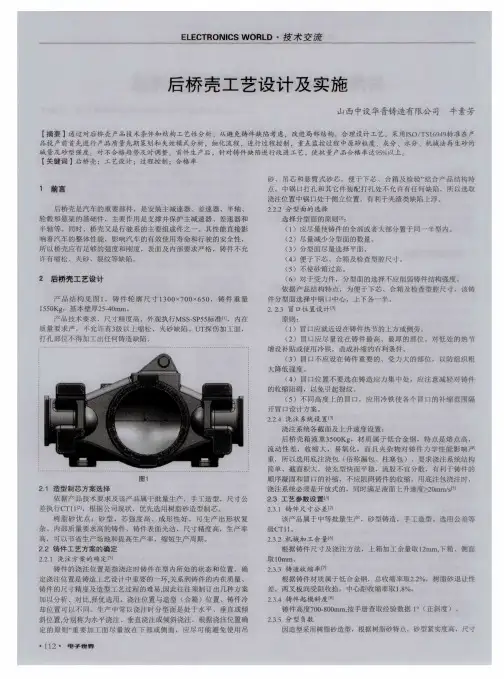
汽车后桥壳体的工艺工装设计摘要三大类的毕业设计课题分别为,工艺工装设计类、组合机床设计类以及计算机课题类。
所选课题所涉及的是工艺工装设计,设计任务为汽车后桥壳体的工艺工装设计,在汽车后桥壳体内装有主传动器、差速器、半轴等传动机构。
壳体起到保证和支撑两方面作用,它的主要加工表面为端面外圆、法兰平面、弹簧座平面、和内孔等。
此次设计主要包括工艺规程、夹具、刀具和量具的设计。
本次设计一共分三个主要阶段,为:(1)毕业实习阶段(2)课题设计阶段(3)考核答辩阶段。
根据此次设计零件的特性,在设计过程中共完成两套夹具及一套工艺规程:两套夹具分别为:(1)铣床夹具(2)钻床夹具,其中,铣床夹具为手动夹紧。
另外并根据任务书分别设计刀具——一把铣刀和量具——单头双极限卡规一套,总共完成图纸约5张,老师所分配的任务基本完成。
关键词:汽车后桥;工艺分析;设计任务ABSTRACTThe subject of the graduation project is divided into three big classes,namely the frock designing type of craft ,making up the designingtype of lathe and comper subjects basically.What this subject involved is the first kind,designing the task for the rear axle of automobile,the craft frock of the shell is designed.Equipped with the organizations of the transmission,such as main hammer mechanism actuator,differential mechanism,semi-axis,ect,within the shell.The shell plays a role in guatanteeing and support,it processes flange,spring seat plane,and interior hole round for outside of the terminal surface of surface,ect,mainly.This design includes the design of rules of craft,jig,cutter and measuring tool mainly.This design divides three stages altogether,namely:(1)Graduation field work stage(2)Ddeign phase of subject(3)Examine the stage of bine this charateristic of designing the part,finisshes one set of rules of craft in the design,two sets of jigs:(1)Jig of the milling machine(2)The jig of the drilling machine,among them,the former,in order to clamp manually.Still design the cutter sepatately according to the task book in addition—One milling cutter is with measuring,finish drawing amount nearlu 5 altogether,finish the task that a teacher assigns basically.Key word:The rear axle of automobile;the crafu analuses;designs the task目录1 绪论 (1)1.1 目前国内汽车后桥制造业的近况和发展前景 (1)1.2 汽车后桥壳体的结构 (1)1.3 汽车后桥壳体的性能刚需 (2)2 零件的分析 (3)2.1 零件的功用 (3)2.2 零件的工艺分析 (4)2.3 生产类型的拟定 (5)2.4 确定毛坯的制造形式 (5)2.5 基面的选择 (5)3 械加工工艺路线 (6)3.1 工艺方案 (7)3.2 工艺方案比较及分析 (8)3.3 划分加工阶段和安排检验工序 (8)4 加工余量、工序、毛坯尺寸的确定 (10)5 工时定额 (11)5.1工序六的工时定额 (11)5.2工序十三的工序定额 (12)6 夹具设计 (13)6.1 铣床夹具设计 (13)6.1.1 工件的加工及其工艺分析 (13)6.1.2 选定方案和定位元件的设计 (13)6.1.3 确定夹紧方式及夹紧结构的设计 (14)6.1.4 分析定位误差的 (15)6.1.5 夹紧元件的强度校核 (16)6.1.6 夹具体的设计 (16)6.1.7 夹具体设计及其操作的说明 (16)6.2 钻床夹具的设计 (17)6.2.1 选择合理的定位基准 (17)6.2.2 夹紧力的确定 (17)6.2.3 钻削力的计算 (18)6.2.4 动力源的设计 (18)6.2.5 夹具体的设计 (20)6.2.6 夹具设计和操作重点说明 (20)7 CAD绘图简介 (21)8 量具设计 (22)9 刀具设计 (25)结论 (27)致谢 (28)参考文献 (29)1 绪论1.1目前国内汽车后桥制造业的近况和发展前景汽车作为现代化交通工具,我国汽车行业发展,工业经济振兴,自主品牌汽车已经迅速开拓出新天地。

引言毕业设计是学生的最后一个教学环节,我这次毕业设计的题目是某汽车后桥减速器壳工艺规程设计及其夹具设计。
汽车在正常行驶时,发动机的转速很高,只靠变速箱来降低,会使变速箱的尺寸增大。
同时,转速下降,扭矩必然增加,也就加大了变速箱与变速箱后一级传动机构的传动负荷。
因此,在动力向左右驱动轮分流的差速器之前需要设置一个主减速器。
而主减速器壳是汽车后桥主减速器的一部分。
主减速器壳体加工精度的高低直接影响着差速器壳及主、被动齿轮的配合精度,因而其加工工艺直接影响车桥和整车质量。
我此次毕业设计的任务是对汽车后桥减速器壳进行工艺分析并且设计其夹具。
经过查阅相关资料,并且结合所学的机械知识,对该零件进行工艺分析,确定出合理的加工工艺方案,并选择切削用量及其工艺装备。
了解零件的结构特点及技术要求,查阅相关书籍,例如夹具方面的教材及图册,经过反复的研究、设计、比较、试验,最终设计出一套合理的夹具,即车法兰止口的夹具。
最后在老师和同学的帮助下,经过不断地修改、检查,最终完成了汽车后桥减速器壳工艺规程及其夹具设计。
本次毕业设计使我在机械方面受益匪浅。
特别是刘老师在工作中对我的耐心辅导,他对学生强烈的责任感和严谨的治学态度,无不给我以深刻的影响。
由于类似的大型课题很少接触,经验能力方面的欠缺,错误之处一定存在,恳请各位老师给予批评指正,以便今后的工作尽善尽美。
第1章零件的分析1.1减速器壳在汽车上的位置及功用汽车正常行驶时,发动机的转速通常在2000至3000r/min左右,如果将这么高的转速只靠变速箱来降低下来,那么变速箱内齿轮副的传动比则需很大,而齿轮副的传动比越大,两齿轮的半径比也越大,换句话说,也就是变速箱的尺寸会越大。
另外,转速下降,而扭矩必然增加,也就加大了变速箱与变速箱后一级传动机构的传动负荷。
所以,在动力向左右驱动轮分流的差速器之前设置一个主减速器,可使主减速器前面的传动部件如变速箱、分动器、万向传动装置等传递的扭矩减小,也可变速箱的尺寸质量减小,操纵省力。
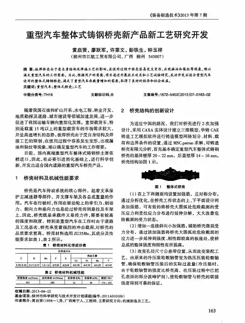
摘要:桥壳后盖法兰翘曲变形过大影响桥壳焊接质量,易造成开焊、漏油缺陷。
利用有限元模拟分析后盖法兰翘曲原因,根据分析结果开发出后盖拉深新工艺,通过镦挤圆角区域消除圆角区周向凸起、减小制件扭曲变形、控制回弹,从而减小制件法兰翘曲变形,并设计拉深模具进行试验验证,充分证明新工艺在解决后盖法兰翘曲问题上的效果。
关键词:桥壳后盖法兰翘曲变形中图分类号:TG386.3+2文献标识码:BDOI :10.19710/ki.1003-8817.20180260桥壳后盖拉深新工艺谢连庆1徐成林1李祎1关雨墙1王强2倪大龙1郑生虎1赵振声1(1.一汽解放汽车有限公司商用车开发院,长春130011;2.一汽解放汽车有限公司车桥分公司,长春130011)作者简介:谢连庆(1983-),男,高级工程师,本科,研究方向为冲压技术。
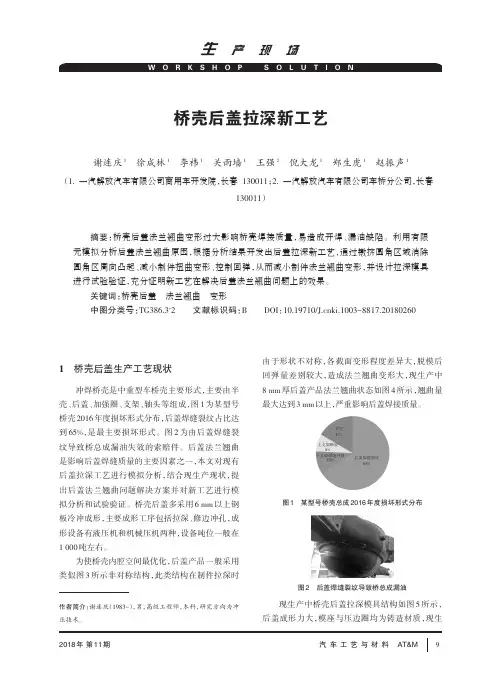
1桥壳后盖生产工艺现状冲焊桥壳是中重型车桥壳主要形式,主要由半壳、后盖、加强圈、支架、轴头等组成,图1为某型号桥壳2016年度损坏形式分布,后盖焊缝裂纹占比达到65%,是最主要损坏形式。
图2为由后盖焊缝裂纹导致桥总成漏油失效的索赔件。
后盖法兰翘曲是影响后盖焊缝质量的主要因素之一,本文对现有后盖拉深工艺进行模拟分析,结合现生产现状,提出后盖法兰翘曲问题解决方案并对新工艺进行模拟分析和试验验证。
桥壳后盖多采用6mm 以上钢板冷冲成形,主要成形工序包括拉深、修边冲孔,成形设备有液压机和机械压机两种,设备吨位一般在1000吨左右。
为使桥壳内腔空间最优化,后盖产品一般采用类似图3所示非对称结构,此类结构在制件拉深时由于形状不对称,各截面变形程度差异大,脱模后回弹量差别较大,造成法兰翘曲变形大,现生产中8mm 厚后盖产品法兰翘曲状态如图4所示,翘曲量最大达到3mm 以上,严重影响后盖焊接质量。
现生产中桥壳后盖拉深模具结构如图5所示,后盖成形力大,模座与压边圈均为铸造材质,现生图1某型号桥壳总成2016年度损坏形式分布图2后盖焊缝裂纹导致桥总成漏油其它17%后盖焊缝裂纹65%上支架断裂8%下支架焊缝开裂10%产模具上垫块9尺寸较小,上底板1压靠上垫块9容易造成上底板1和压边圈7局部压堆变形,需要做镶块防止压堆变形。
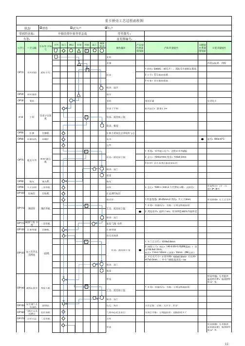
大吨位卡车后桥壳的加工工艺设计
二、零件加工工艺路线
毛坯件制造方法的选择
现代汽车,尤其重型汽车,其驱动桥壳承载很重,多采用使用整体式桥壳结构。
常见的整体式桥壳制造方式有整体铸造式、钢板冲压焊接式、钢管扩张成形式等。
整体铸造式桥壳是汽车发展史上最早采用的结构,主要优点在于刚性好、塑性变形小、强度高、易铸成等强度梁,可根据各截面不同的强度要求设计铸造不一样的壁厚。
砂型铸造可以铸造外形和内腔
三、各工艺方法加工工序的制定
制定工艺路线的出发点是:在保证零件的尺寸精度、位置精度和几何外形等技术要求的前提下,制定出更合理、更经济和更高效的加工方法。
铸造
预先热处理
升温;
第一阶段石墨化;
中间阶段冷却;
第二阶段石墨化;。
汽车后桥壳体加工工艺规程及夹具设计摘要汽车后桥壳体是汽车的重要组成部分,它与主减速器、差速器和车轮传动装置组成驱动桥。
驱动桥处与动力传动系的末端,其基本功能是增大由传动轴或变速器传来的转矩,并将动力合理的分配给左、右驱动轮,另外还承受作用于路面和车架或车身之间的垂直力、纵向力和横向力。
它连接主减速器传动力,支撑差速器及半轴实现俩车轮差速转动;尺寸比较大,主要承受载荷。
重点是保证壳体的强度和刚性性能,便于安装、调整和维修。
汽车后桥壳体一般采用铸铁铸造成型,在经过机械加工将其加工至使用要求,在生产过程中,汽车后桥壳体的加工工艺定制非常重要,工艺的编制决定了零件的精度及生产效率,尤其是这种大批量生产的零件,其工艺规程要考虑到产量问题。
同时为了保证工件的加工精度,以及为了提高生产率而设计出各个工序的专用夹具,是操作者使用起来简单、快速、准确,从而在保证精度的前提下大大提高生产率。
关键词:工艺编制,加工时间,专用夹具,生产率ABSTRACTAbstractAutomobile rear axle housing is an important part of the car, it with the Lord reducer, differential and wheel gear drive axle. Drive axle and the end of the power transmission system, its basic function is to increase the shaft or the transmission of torque, and power reasonable distribution to the left and right driving wheels, also bear role between road surface and frame or body of vertical force and vertical force and horizontal force. It connects the main reducer momentum, supporting both differential and half shaft wheel differential rotation. Size is larger, the main load bearing. The key is to ensure that shell strength and rigidity performance, ease of installation, adjustment andmaintenance.Automobile rear axle housing is made of cast iron casting forming, generally after machining to its processing to use requirement, in the process of production, the processing technology of the automobile rear axle shell custom is very important, the process of making determines the accuracy of the parts and the production efficiency, especially in the mass production of parts, the technical process to production into consideration. At the same time, in order to ensure the workpiece machining accuracy, and in order to improve the productivity and special fixture design of each process, is the operator to use simple, rapid and accurate, and on the premise of guarantee accuracy greatly improved productivity.Key words: machining process, machining time, special fixture, productivity目录第一章加工工艺规程设计 (3)1.1 零件的分析 (3)1.1.1 零件的作用 (3)1.2 汽车后桥壳体加工的问题和工艺过程设计所应采取的相应措施(2)1.2.1 孔和平面的加工顺序 (4)1.2.2 孔系加工方案选择 (2)1.3 汽车后桥壳体加工定位基准的选择 (2)1.3.1 粗基准的选择 (2)1.3.2 精基准的选择 (3)1.4 汽车后桥壳体加工主要工序安排 (3)1.5 机械加工余量、工序尺寸及毛坯尺寸的确定 (5)1.6确定切削用量及基本工时(机动时间) (5)第二章钻2-M8螺纹孔夹具设计 (19)2.1定位基准的选择 (19)2.2 钻削力计算 (19)2.3定位元件的设计 (20)2.4 定位误差分析 (21)2.5 夹紧装置及夹具体设计 (21)2.6 夹具设计及操作的简要说明 (21)第3章铣178下平面夹具的设计 (22)3.1 问题的指出 (22)3.2 定位机构 (22)3.2.1定位方式计算及选择 (22)3.2.2切削夹紧力的计算 (22)3.3定位误差分析 (24)3.4 零、部件的设计与选用 (24)3.4.1定位销选用 (24)3.4.2夹紧装置的选用 (25)3.5 夹具设计及操作的简要说明 (27)结论 (28)参考文献 (29)致谢 (30)第一章零件加工工艺规程以及设计1.1零件结构的分析1.1.1 零件作用的分析随着科学技术和社会生产水平的不断提高,机械制造生产模式发生了巨大的演变。
桥壳加工工艺流程
桥壳加工工艺流程:使用立式加工中心进行铣簧面、钻镗孔等工序、利用卧式加工中心进行铣面、镗钻孔、攻丝等操作、使用专用数控铣床对特定面(如琵琶面)进行铣削、专用组合钻进行钻孔和攻丝操作、立式加工中心进行表面铣、钻、攻丝等工序,并对半轴衬套孔进行粗镗。
加工两端桥壳法兰和止口、利用组合镗床进行半轴套孔的精密镗削、组合钻孔机对法兰进行钻孔、攻丝操作、专用铣床进行桥壳内部结构的铣削,如刨杆轴承面、桥壳专用清洗机进行桥壳清洗、抗扭焊机进行焊接孔的操作、数控桥壳专用车床对两端法兰进行精细车削、最后进行整体检查验收。
课程
设计
说明
书
一、桥壳性能要求及材料的确定
1.性能要求
重型卡车后桥壳作为驱动桥壳,是汽车的主要零件之一,它的功用是支承并保护主减速器、差速器和半轴等,使左右驱动车轮的轴向相对位置
固定;另外驱动桥桥壳是汽车上重要的承载件和传力件。
驱动桥的桥壳不仅支承汽车重量,将载荷传递给车轮,而且还承受由驱动车轮传递过来的牵引力、制动力、侧向力、垂向力以及反力矩,并经
悬架传给车架。
在汽车行驶过程中,受道路条件的影响,桥壳会受到车轮
与地面间产生的冲击载荷,可能引起桥壳变形或折断。
因此,驱动桥壳应
具有足够的强度、刚度和良好的动态特性,且质量要小,并便于主减速器
的拆装和调整。
2.材料确定
桥壳材料通常可采用球墨铸铁、可锻铸铁或铸钢铸造,由于可锻铸铁具有较高的强度、塑性和冲击韧性,适于制造形状复杂、承受冲击和振动
载荷的薄壁零件,故本设计采用可锻铸铁( KTH350-10)。
3.毛坯零件图
二、零件加工工艺路线
1.毛坯件制造方法的选择
现代汽车,尤其重型汽车,其驱动桥壳承载很重,多采用使用整体式桥壳结构。
常见的整体式桥壳制造方式有整体铸造式、钢板冲压焊接式、
钢管扩张成形式等。
整体铸造式桥壳是汽车发展史上最早采用的结构,主
要优点在于刚性好、塑性变形小、强度高、易铸成等强度梁,可根据各截
面不同的强度要求设计铸造不一样的壁厚。
砂型铸造可以铸造外形和内腔
十分复杂的毛坯,能适应各种大中小型铸件,且铸件形状与零件尺寸比较
接近,减少切削加工余量。
本设计采用砂型铸造的方法来完成毛坯件的加
工。
2.后续加工方法
后续加工为:预先热处理(石墨化退火)——机械加工——最终热处理(淬火+回火)
3.毛坯结构分析
为进一步提高整体铸造式桥壳的强度和刚度,常在桥壳两端压入较长的无缝钢管作为半轴套管,每边半轴套管与桥壳的压配表面共四处,由里向外逐渐加大配合面的直径,以得到较好的压配效果。
钢板弹簧座与桥壳铸成一体,故在钢板弹簧座附近桥壳的截面可根据强度要求铸成适当的形状,通常多为矩形。
安装制动底板的凸缘与桥壳铸在一起。
桥壳中部前端的平面用于安装主减速器及差速器总成,对于重卡常将后盖与桥壳做成一体。
三、各工艺方法加工工序的制定
制定工艺路线的出发点是:在保证零件的尺寸精度、位置精度和几何外形等技术要求的前提下,制定出更合理、更经济和更高效的加工方法。
1.铸造
2.预先热处理
(1)升温;
(2)第一阶段石墨化;
(3)中间阶段冷却;
(4)第二阶段石墨化;
(5)出炉冷却。