DLink交换机管理设置快速配置手册运营商行业
- 格式:doc
- 大小:680.50 KB
- 文档页数:10


/192/81.htmlD-Link宽带路由器设置全攻略,为了更好讲解Dlink路由器设置方法,我们今天以D-Link的di-740p型号,默认管理地址为192.168.0.1,管理端口是8080的路由器作为实验讲解。
首先将一台计算机的ip地址和路由器管理地址设置在同一网段,例如192.168.0.2,打开192.16-D-Link宽带路由器设置全攻略,为了更好讲解Dlink路由器设置方法,我们今天以D-Link的di-740p型号,默认管理地址为192.168.0.1,管理端口是8080的路由器作为实验讲解。
首先将一台计算机的ip地址和路由器管理地址设置在同一网段,例如192.168.0.2,打开192.168.0.2计算机的浏览器,在地址栏输入“http://192.168.0.1:8080”后按回车键即出现用户登陆提示窗口,输入宽带路由器说明书中的默认管理账户和密码进入宽带路由器设置界面。
为了让路由器能够自动拨号,我们还需要将ADSL账号集成到路由器中。
点击上方的“首页”标签,然后点击作变的“W AN”,在PPPoverEthernet处看到设置ADSL账号的地方,输入自己申请的ADSL账号和密码后保存设置。
现在到“系统状态”标签中的“系统信息”处察看联网状态,在W AN端可以清晰地看到ADSL拨号获得的网络信息。
设置完ADSL账号后,我们就可以通过宽带路由器上网了,不过为了更好的管理和提高安全性还需要进行如下操作:点击“首页”标签,然后在左边选择“DHCP”,在DHCP服务器可进入的ip范围处设置ip地址范围,保存后宽带路由器就具备自动分配ip地址的功能了。
默认设置所有连接到路由器的计算机都是受到保护的,也就是说处于内网中,使用bt等p2p软件会受到一定的影响。
我们可以用“进阶设定”标签中的“DMZ”来设置宣告的主机。
在这里设置的主机就暴露在网络中,一方面可以无所顾虑地使用bt下载软件和建立进入宽带路由器设置界面中的过滤器标签,我们可以对数据报的来源及地址进行多种项目的过滤,包括ip地址、url信息、mac地址以及区域信息等。

交换机配置说明1、把交换机的控制口和PC机的串口相连,通过超级终端进入交换机的配置界面,如下图:打开交换机电源,自检后出现下面的登陆画面,按二次回车键进入主菜单,2、按TAB键,光标移到Switch Settings,按回车。
3、切换到Switch Operation Mode,按回车。
4、用空格转换到下图的设置,在切换到APPL Y,按回车。
5、按Y键6、等待重起后进入主菜单。
7、按TAB键切换到VLANS,按回车。
8、按TAB键,光标移到Configure 802.1Q Port Settings,按回车。
9、用TAB键在项目之间切换,数字值直接用数字键输入,其他非数字值用空格切换,改完后切换到APPL Y,搂回车。
10、将1端口的PVID值改为10、2端口的PVID值改为20、3到6端口的PVID值改为30、7到8端口的PVID值改为40。
11、按ESC键回到上一级菜单,按TAB键切换到Edit 802.1Q VLANS,按回车。
12、依画面设置VLAN10、VLAN20、VLAN30、VLAN40。
13、按ESC键回到主菜单,切换到Layer 3 IP Networking,按回车。
14、切换到Setup IP Interface,按回车。
15、Action:用空格切换到下图所示Interface Name:直按输入字母或数字,为接口取名字IP Address :直接输入IP地址,192.168.0.254Subnet Mask:直接输入子网掩码,255.255.255.0VID;直接输入数字,10Active:用空格切换到“YES”设置后,切到APPL Y,按回车。
16、同上设置VLAN20、VLAN30、VLAN40的Interface Name。
17、按ESC回到主菜单,切换到Forwarding,按回车。
18、按TBA键。
切换到期Static/Default Routes,按回车。

關於本指南本指南提供設定D-Link 智慧型交換器的的說明,請注意您購買的產品可能與下列說明有些許差異。
更多關於您的交換器細節資訊、配件、設定網連接路與技術規格,請參閱產品包裝中的使用手冊。
步驟 1 – 打開包裝小心打開包裝後,請參閱包裝內容物資料,確認所有品項數量正確以及均正常沒有損壞,假如有任何品項遺失或損壞,請聯絡當地的零售商更換。
- D-Link Web 智慧型交換器。
- 機架固定架。
- 電源線。
- 使用手冊光碟片(包含SmartConsole Utility program)。
- 多國語言版設定指南。
步驟2 – 交換器安裝為了讓交換器安裝與運作安全,建議您以下幾件事情:♦檢查電源線的外表,並確認AC電源連接插頭是安全的。
♦請確認交換器周圍為適當的通風散熱環境。
♦不要放重物在交換器上。
桌上型或架上行安裝當安裝交換器在桌上或架子上,產品包裝內的橡膠腳墊請安裝至交換器底部的四個角落,讓交換器與桌面有適當的通風空間。
圖 1. 安裝橡膠腳墊機架安裝交換器可以安裝在EIA標準尺寸的19吋機架,安裝時,請將利用螺絲將機架固定架固定鎖緊在交換器的側面(兩邊均要安裝)。
圖 2. 固定機架固定架然後,使用包裝內所提供的螺絲,將交換器鎖到機架上面。
圖 3. 安裝交換器到標準尺寸的機架步驟3 – 將AC電源線連接至交換器您可以連接AC電源線至交換器後方的的電源插孔(電源插孔最好具備接地或高壓保護機制)圖 4. 將交換器電源插上牆壁插座電源中斷為了預防危險,如果發生電源中斷,請立即拔掉插座,當電源回覆,請將電源插上。
管理設定D-Link Web 智慧型交換器使用Web-based Management Utility,可以經由設備上的任何網路連接埠管理,或可以透過任何電腦使用SmartConsole Utility進行管理。
假如您僅想要管理一部D-Link Web 智慧型交換器,Web-Based Management Utility將會是比較好的選擇,每部交換器會取得自己的IP 位址,可以讓Web-Based Management Utility或SNMP網路管理者或電腦在相同的IP網段進行通訊溝通之用。

D-Link交换机设备安全性功能配置手册友讯网络D-Link2012年4月目录1、风暴抑制 (2)1)广播抑制 (2)2)组播抑制 (4)3)未知单播抑制 (5)2、Safe Guide配置 (8)1)配置需求 (8)2)配置过程 (8)3)测试验证 (9)3、MAC地址绑定配置 (10)1)配置需求 (10)2)配置思路 (10)3)验证测试 (11)4、IP+MAC+PORT绑定 (12)1)组网需求 (12)2)组网图 (12)3)配置步骤 (12)5、DHCP_Snooping (17)1)功能介绍 (17)2)功能作用 (17)3)配置范例 (18)6、端口隔离配置 (21)1)配置要求 (21)2)配置实例 (21)1、风暴抑制风暴抑制是防止交换机的端口被局域网中的广播、组播或者一个物理端口上的单播风暴所破坏。
当流量在局域网中泛洪,建立的过多的流量将占用过多的带宽,并导致网络拥塞。
风暴抑制用于对进入的流量进行控制,从上面我们可以看出控制的对象可以是单播、广播和组播流量。
我们通过事先定义一个门限值(threshold),当某种流量超出了门限值,将对该流量进行控制,使其降到门限值一下,一旦流量超出门限值,所有的进入交换机的流量(无论是单播、组播还是广播)都会被丢弃!风暴抑制在交换机上默认是关闭。
D-link的交换机具有抑制广播、组播、单播三种风暴的能力,下面以DGS-3120-24TC为例,介绍如何对风暴抑制进行设置。
1)广播抑制1、进入交换机的配置界面。
2、输入以下命令:config traffic control 1:1-1:10 broadcast enable:在交换机第一个端口至第十个端口开启广播抑制。
threshold 128000 action shutdown :当交换机作用端口接收到超过每秒128000个数据包时,关闭该端口。
每秒通过的数据包数值可以自行设置,范围在0—255000之间。

D-LINK3226交换机设置说明一、在浏览器地址栏中输入交换机的IP地址,出现以下界面:
点击Login,输入用户名和密码,京沪铁路用户名和密码都为scbj。
出现以下界面
设置IP地址、子网掩码、网关如下:
二、避免自环死机,需对讯飞服务器、客户端、笔记本端口进行端口安全设置。
选中需要设置的端口,点击Edit
参数设置以下方式
设置完成后需保存设置,点击Save Changes 然后重启系统,点击左边restart system
重启系统后参数更改就生效。
三、有关生成树设置
选中Advanced setup下的spanning tree 下的stp Switch settings,出现以下界面
这是京沪铁路视频的根结点,Priatity(0-61440)设置为12288,其它交换机应再加上1024的倍数。
环网这个参数的值应该是两头最小,往环中间逐渐增加。
设好后也需保存参数并重启系统。

UPD-LINK SWITCH通用配置手册0、设置管理员帐户#create account admin/user<username> admin/user是用户类型Enter a case-sensitive new password:***Enter the new password again for confirmation:***Success.#delete account <username>#show account1、配置交换机默认IP地址和所属VLANconfig ipif System ipaddress 192.168.0.2/24 vlan V302、配置SNMPcreate snmp community test view CommunityView read_onlycreate snmp community testw view CommunityView read_writeshow snmp community3、配置VLAN#create vlan v30 tag 30 其中,v30是VLAN Name ,30是VLAN ID (VID)#config vlan v30 add untagged 1:23-1:24 PORT 23、24添加到vlan v30中,并打上untagged标记#config vlan v30 advertisement enable4、端口配置语法:config ports [<portlist | all> [speed [auto | 10_half | 10_full | 100_half | 100_full | 1000_full {[master | slave]} ] | flow_control [enable | disable] | learning [enable | disable] state [enable | disable] description <desc 32> | clear]例:#config ports 23-24 speed 100_half learning enable state enable flow_control enable5、配置链路聚合组语法:#create link_aggregation group_id <value 1-32> {type [lacp | static]}#config link_aggregation group_id <value 1-32> {master_port <port> | ports <portlist> | state [enable |disable]例:#config link_aggregation group_id 1 master_port 1:5 ports 1:5-1:7, 1:96、端口镜像enable mirrorconfig mirror port <port> [add/delete] source ports <portlist> [rx/tx/both]<port>监控端口;source ports 被监控端口7、软件升级download firmware 10.90.90.92 升级firmwareupload configuration 172.18.192.90 <filename> 上传配置到TFTP服务器download configuration 172.18.192.90 <filename> 从TFTP服务器下载配置8、Ip Interface的配置语法:creat ipif <ipif name > <network address > <vlan name > state enable例:creat ipif test 192.168.1.1/24 vlan100 state enableconfig ipif System ipaddress 10.48.74.122/8 vlan v309、MAC绑定到交换机端口(手动添加MAC,这些MAC的终端可以使用此端口)Used to create a static entry to the unicast MAC address forwarding table (database)1、语法:create fdb <vlan_name 32> <macaddr> [port <port>] 建立静态fdb条目例:create fdb default 00-00-00-00-01-02 port 2:52、语法:config ports learning disable 关掉端口学习功能10、MAC锁定到交换机端口(设定使用端口的终端-MAC的数量,并锁定当前连接的终端-MAC为许可用户)语法:config port_security ports [<portlist>| all ] {admin_state [enable | disable] | max_learning_addr <max_lock_no 0-64> | lock_address_mode [Permanent | DeleteOnTimeout | DeleteOnReset]}例:config port_security ports 1:16 admin_state enable max_learning_addr 10 lock_address_mode DeleteOnReset11、traffic_segmentation(同一VLAN内端口隔离功能)语法:config traffic_segmentation [<portlist>| all] forward_list [null | all | <portlist>]例:config traffic_segmentation 1:1 forward_list 1:1-1:10 (Port1可以和Port1-10通讯,和Port 11-24隔离)12、带宽控制语法:config bandwidth_control [<portlist> | all] {rx_rate [no_limit | <value 1-999>] | tx_rate [no_limit | <value 1-999>]} 单位为Mbps13、创建IP interface语法:create ipif <ipif_name 12> ipaddress <network_address> vlan <vlan_name 32> state [enable | disable]例:create ipif p1 ipaddress 10.1.1.1 Trinity state enable14、设置静态路由语法:create iproute <network_address> <ipaddr> {<metric 1-65535>} {[primary | backup]}<network_address> . IP address and netmask of the IP interface that is the destination of the route.<ipaddr> . The gateway IP address for the next hop router.语法:create iproute default <ipaddr> {<metric 1-65535>}15、ACL访问控制列表1、创建access_profileDXS-3350SR:4#create access_profile ip destination_ip_mask 255.255.255.255 profile_id 12、建立access条目DXS-3350SR:4#config access_profile profile_id 1 add access_id 1 ip destination_ip 172.18.192.246 port 1:16 deny16、IP-MAC BindingThe IP-MAC Binding commands in the Command Line Interface (CLI) are listed (along with the appropriate parameters) in the following table.Commandcreate address_binding ip_mac ipaddress <ipaddr> mac_address <macaddr>config address_binding ip_mac ipaddress <ipaddr> mac_address <macaddr>config address_binding ip_mac ports [<portlist> | all] state [enable | disable]showeg:enable address_binding acl_mode Enable IP-MAC Port Binding ACL Modecreate address_binding ip_mac ipaddress 192.168.0.10 mac_address 00-15-F2-A9-0B-C2 ports 1 mode acl ⎝ To set up a IP-MAC Port Binding Rule config address_binding ip_mac ports 1-10 state enable ⎝ Enable active portshow address_binding ip_macshow address_binding ports17、策略路由create access_profile profile_id 1 ip source_ip_mask 255.255.255.0config access_profile profile_id 1 add access_id 1 ip source_ip 4.4.4.4 port 1create policy_route name 1config policy_route name 1 acl profile_id 1 access_id 1 nexthop 2.2.2.2 state enable18、DHCP Servercreate dhcp pool testconfig dhcp pool network_addr test 192.168.0.0/24config dhcp pool dns_server_address test 61.139.2.69 0.0.0.0 0.0.0.0config dhcp pool netbios_node_type test broadcastconfig dhcp pool default_router test 192.168.0.1 0.0.0.0 0.0.0.0config dhcp pool lease test 1 1 1config dhcp ping_packets 5config dhcp ping_timeout 500enable dhcp_server19、修改交换机名称config command_prompt <name>20、线缆检测diag_cable ports <portlist>21、三层组播协议enable igmp_snoopingconfig igmp_snooping all state enableconfig igmp all state enableenable DVMRPconfig DVMRP all state enable22、开启DHCP Server Screening功能config filter dhcp_server add permit server_ip 10.10.10.1 client_mac 00-90-27-e0-67-27 port 1:1-1:24 config filter dhcp_server ports <端口> state enable23、开启DHCP中继功能enable dhcp_relayconfig dhcp_relay add ipif <三层接口名称> <DHCP服务器的IP>24、保存配置文件upload cfg_toTFTP <TFTP IP地址> dest_file c:\cfg\DGS-3420.cf。

D-Link无线路由器当交换机怎么设置D-Link无线路由器当交换机怎么设置首先,先介绍一下配置步骤:1、更改LAN口IP;2、关闭DHCP服务器;3、配置无线AP;4、设备连接。
然后这台无线路由器就可以当成交换机来使用了。
更改LAN口IP更改说明D-Link DIR 600无线路由器的LAN口默认IP地址是192.168.0.1,如果原来的网络中有设备也使用了192.168.0.1这个IP地址,则需要把D-Link DIR 600无线路由器的LAN口IP地址更改为局域网中一个未被使用的IP地址;如果局域网中没有设备使用该IP地址,则可以不用更改。
更改方法1、在D-Link DIR 600无线路由器的管理界面中,点击设置网络设置在路由器IP地址后面进行更改(本例更改为192.168.0.100) 点击保存设定。
2、在弹出的对话框中点击确定3、点击确定后,路由器会自动重启,重启完成后可以用新的管理地址登录管理界面。
关闭DHCP服务器点击点击设置网络设置启用DHCP服务选择:关闭点击保存生效。
配置无线AP配置说明需要把D-Link DIR 600无线路由器的无线网络配置为无线AP模式,这样无线网络也可以成为交换机的无线接入点。
配置方法点击设置无线设置无线工作模式选择:AP模式点击保存设定。
设备连接完成以上的配置后,需要把D-Link DIR 600无线路由器连接到局域网中,注意在原来的网络中的网线一定要插在D-Link DIR 600路由器的LAN接口上面,也就是当成交换机用时,WAN 口是不能使用的。
D-Link无线路由器的WDS桥接怎样设置D-Link无线路由器的WDS桥接怎样设置D-Link无线路由器WDS桥接的设置方法查看无线MAC地址首先我们需要获取AP1和AP2这2台路由器的无线MAC 地址,注意:这里是获取的无线MAC地址,不是LAN或者WAN 口的MAC地址;查看方法是:在D-Link路由器的管理界面点击状态系统信息找到下方的无线网络选项下面的MAC地址。

Before Your BeginThis Quick Installation Guide gives step-by-step instructions for setting up the D-Link DES-1228 Fast Ethernet Smart Switch. The model you have purchased may appear slightly different from those shown in the illustrations. For more detailed information about the switch, its components, making network connections and technicalspecifications, please refer to the User’s Manual on the CD included with your switch.Check Your Package ContentsThese are the items included with your DES-1228 purchase:©2006 D-Link Systems, Inc. All rights reserved. Trademarks or registered trademarks are the property of their respective holders. Software and specifications subject to change without notice.Using a power supply with a different voltage rating will damage and voidDES-1228D-Link 24-Port 10/100Mbps with 4 10/100/1000Base-T ports and 2 Combo SFPSmart Switch2Setup for the DES-1228 Fast Ethernet Smart SwitchBefore physically installing the switch, please make note of the following recommendations:A. Install the DES-1228 in a fairly cool and dry place. TechnicalSpecifications such as operating temperatures and, other important information can be found in the manual located on the supplied CD. B. Install the DES-1228 in a site free from strong electromagnetic fieldgenerators (such as motors), vibration, dust, and direct exposure to sunlight.C. Leave at least 10cm (about 4 inches) of space at the front and rearof the switch for ventilation.D. Visually inspect the DC power jack and make sure that it is fullysecured to the power adapter.E. Install the DES-1228 on a sturdy, level surface that can support itsweight, or in an EIA standard-size equipment rack. F. When installing the Switch on a level surface, attach the rubber feetto the bottom of each device. The rubber feet cushion the switch and protect the switch case from scratching.Attach the adhesive rubber pads to the bottomRack MountingThe DES-1228 can be mounted in an EIA standard-size, 19-inch rack, which can be placed in a wiring closet with other equipment. Attach the mounting brackets to both sides of the Switch (one at each side), andsecure them with the provided screws.Use the screws provided. Then use screws provided with theequipment rack to mount the Switch in the rack.Mount the Switch in the rackConnecting Network CablesThe D E S-1228 has 24 ports that support 10/100Mbps Fast Ethernet;it also has 4 10/100/1000Base-T Ports and 2 Combo SFPs. It runsfull/half duplex transfer mode for 10/100Mbps and full duplex transfermode for 1000Mbps. Each port on the DES-1228 supports Auto-MDI/MDI-X. Auto-MDI/MDI-X is a feature that enables the switch toauto sense what kind of cable is used on a port (straight or crossover).This allows any type of cables to be used with the switch regardlessof what device is being connected.AC PowerThe Switch utilizes an AC power supply of 100~240V AC, 50~60Hz. Thepower switch is located at the rear of the unit adjacent to the AC powerconnector and the system fan. The switch’s power supply will adjust tothe local power source automatically and may be turned on withouthaving any or all LAN segment cables connected.3Connecting The DES-1228 Fast Ethernet Smart Switch To YourNetworkFront Panel10/100 Base-TX Mini GBIC PortsTwisted-Pair Ports┌──────────────┐┌┘└────────┘└──┘LED Indicators 10/100/1000 Base-T Twisted Pair Ports 10/100 BASE-TX Twisted Pair Ports (Port 1~24) The DES-1228 is equipped with 24 Fast Ethernet twisted pair portsthat are auto-negotiable 10/100Mbps and also support auto MDI/MDIXcrossover detection. All these 24 ports can operate in half- and full-duplex modes.10/100/1000 BASE-T / Mini GBIC Combo Ports (OptionPort 25~26)The Switch is also equipped with two combo 10/100/1000 Base-T /Mini GBIC ports, supporting optional 100BASE-FX or 1000BASE-SX/LX Mini GBIC modules for fiber uplinks.10/100/1000 BASE-T Twisted Pair Ports (Port 27~28) Finally there are 2 Gigabit twisted pair ports that are auto negotiable10/100/1000Mbps with full auto MDI/MDIX crossover detection supportthat can also operate in half- and full- duplex modes.[Note: If the port is set to “Forced Mode”, Auto-MDI/MDIX isdisabled]45LED IndicatorsLED stands for L ight-E mitting D iode .The front panel LEDs provides instant status feedback and simplifies monitoring and troubleshooting tasks.LED indicators of the SwitchPower LEDsOn When the Power LED light is on, the Switch is receiving power.OffWhen the Power LED light is off, the power cord is not or improperly connected.CPU LEDs ( Management Indicator)Blinking When the CPU is working, the CPU LED is blinking. OffThe CPU is idle.Ports 1 ~ 24 Status LEDsLink/Act OnWhen the Link/Act LED light is on, the respective port is successfully connected to an Ethernet network.Blinking When the Link/Act LED is blinking, the port istransmitting or receiving data on the Ethernet network. Off Nolink. 100Mbps OnWhen the 100Mbps LED light is on, the respectiveport is connected to a 100Mbps Fast Ethernet network.OffWhen the respective port is connected to a 10Mbps Ethernet or no link.Option Ports 25~26 10/100/1000 Base-T / Mini-GBIC Status LEDsFX LinkOn When the FX Link LED light is on, the respectiveport is connected to a 100 or 1000Mbps Ethernetnetwork.Off No link or linking the copper ports.Link/ActOn When the respective combo port is connected to anetwork, the Link/Act LED light is on.Blinking When the LED is blinking, the respective comboport is transmitting or receiving data on a network.link.Off No1000MbpsOn When1000Mbps LED light’s on, the respectivetheport is connected to a 1000Mbps Gigabit Ethernetnetwork.Off When the respective port is connected to the100Mbps Fast Ethernet or no link.100MbpsOn When the 100Mbps LED lights on, the respectiveport is connected to a 100Mbps Fast Ethernetnetwork.port is connected to aOff Whenrespectivethe1000Mbps Gigabit Ethernet network or no link.Ports 27~28 10/100/1000 Base-T LEDsLink/ActOn When the Link/Act LED light is on, the respectiveport is successfully connected to an Ethernetnetwork.Blinking When the Link/Act LED is blinking, the port istransmitting or receiving data on the Ethernetnetwork.link.Off No671000MbpsOn When the 1000Mbps LED light is on, the respectiveport is connected to a 1000Mbps Gigabit Ethernet network. OffWhen the respective port is connected to a 10Mbps Ethernet or 100Mbps Fast Ethernet network, or no link.100Mbps OnWhen the 100Mbps LED light is on, the respective port is connected to a 100Mbps Fast Ethernet network.Off When the respective port is connected to a 10Mbps Ethernet or 1000Mbps Gigabit Ethernet network.Installing the SmartConsole UtilityThe SmartConsole Utility allows a user to monitor and configure multiple D-Link Web-Smart Switches from a workstation connected to the network. Follow these steps to install the SmartConsole Utility: 1. Insert the Utility CD in the CD-Rom Drive. 2. From the Start menu on the Windows desktop, choose Run . 3. In the Run dialog box, type D:\SmartConsole Utility\setup.exe( where D:\ represents the drive letter of your CD-ROM) your CD-Rom drive is located) and click OK . 4. Follow the on-screen instructions to install the utility.5. Upon completion, go to Program Files -> SmartConsole Utilityand execute the SmartConsole utility. (Figure 1.)Figure 1. SmartConsole Utility8Configuring the SwitchThe DES-1228 has a Web GUI interface for smart switch configuration. The Switch can be configured through the Web Browser. A network administrator can manage, control and monitor the switch from the local LAN. This section indicates how to configure the Switch to enable its smart functions.Note: Use Internet Explorer 5.5 or above to properly access and view the configuration..LoginIn order to login and configure the switch via an Ethernet connection, the PC must have an IP address in the same range as the switch. For example, if the switch has an IP address of 192.168.0.1, the PC should have an IP address of 192.168.0.x (where x is a number between 2 and 254), and a subnet mask of 255.255.255.0.Open your web browser and enter http://192.168.0.1 (the factory-default IP address) in the address box. Then press <Enter>.The web configuration can also be accessed through the SmartConsoleUtility. Open the SmartConsole Utility and double-click the switch as it appears in the Monitor List. This will automatically load the webconfiguration in your web browser.When the following logon box appears, enter "admin" for the password. Press Ok to enter the main configuration window. (Figure 3.)Figure 3Figure 29Once you have successfully logged in, the device status page will appear. (Figure 4)Setup MenuAll configuration options on the switch are accessed through the Setup menu on the left side of the screen (Figure 5). Click on the setup item that you want to configure. The menu contains the following options: System Setting, Trap Setting, Port Setting, SNMP Setting, Password Access Control, 802.1Q VLAN, Trunking, IGMP Snooping, 802.1DSpanning Tree, Port Mirroring, 802.1p Default Priority, Safeguard Engine, Broadcast Storm Control, 802.1X Setting, Static MAC, Dynamic Forwarding Table and Statistics. (Figure 5).Figure 5Figure 4ToolYou can also find the Tool menu on the main page (Figure 6). Click on it and scroll down as shown in Figure 6, and you can see four options: Reset, Config Backup & Restore, Firmware Backup & Upload and System Reboot.Figure 610。

D-Link 交换机设备管理设置快速配置手册友讯网络D-Link2012年10月目录1、Console管理模式 (2)2、Telnet模式 (5)3、WEB界面管理 (8)D-Link交换机支持3种管理配置方法,分别是Console管理(命令行CLI方式)、Telnet配置(命令行CLI方式)和WEB界面(菜单图形方式)配置。
1、Console管理模式使用交换机配置线连接交换机Console口和调试PC串口,使用Windows操作系统自带的【超级终端】仿真软件对交换机进行配置管理。
首先在“开始”——“程序”——“附件”——“通讯”中打开“超级终端”。
新建连接,输入名称,选择正确的连接端口。
设置端口属性,首先点击“还原默认值”,然后选择“每秒位数(B)”为“9600”:点击“确定”后即可打开交换机Console口配置模式,初始用户名/密码为空,按回车即可。
2、Telnet模式在远程调试交换机设备时,无法使用Console口进行连接,此时可以使用Telnet方式,通过网络远程管理设备。
首先确定交换机的IP 地址,初始默认值为空,无IP,可以通过Console来配置,包括交换机设备当前IP地址、Telnet是否开启等信息。
配置交换机IP打开“命令提示符”界面首先通过ping命令测试管理PC与交换机网络是否连通。
确定网络连通后,使用Telnet命令进行远程调试。
例如!配置只允许192.168.0.0/255.255.0.0这个网段的地址通过telnet访问交换机Dlink(config)#login-access-list telnet 192.168.0.1 0.0.255.2553、WEB界面管理部分用户对命令行CLI方式配置交换机方式比较陌生,可以使用WEB界面来配置交换机。
首先确认交换机IP地址和网络连通性,并确定WEB管理是否开启(具体参照Telnet管理部分)。
如果WEB管理未开启,可通过Console或者Telnet方式下执行enable web命令开启。


D-Link DES-1026G24-Port 10/100Mbps + 2-Port 10/100/1000Mbps Gigabit Ethernet SwitchManualVersion 3.00January 2, 2008Table of ContentsContents (3)1. Package2. Introduction (3)3. Installation (8)Specifications (11)4. TechnicalContents1. PackageOne DES-1026G 24-Port 10/100Mbps + 2-Port10/100/1000Mbps Gigabit Ethernet SwitchOne AC power cordFour rubber feet to be used for shock cushioningScrews and two mounting bracketsManualIf any of the above items are missing, please contact your reseller. 2. IntroductionCongratulations on your purchase of the DES-1026G 24-Port10/100Mbps + 2-Port 10/100/1000Mbps Gigabit Ethernet Switch. This device integrates 1000Mbps Gigabit Ethernet, 100Mbps Fast Ethernet, and 10Mbps Ethernet network capabilities into one cost-effective solution. This manual discusses how to install your DES-1026G 24-Port10/100Mbps + 2-Port 10/100/1000Mbps Gigabit Ethernet Switch.In this manual, the term “Switch” (first letter upper case) refers to your DES-1026G 24-Port 10/100Mbps + 2-Port 10/100/1000Mbps Gigabit Ethernet Switch, and “switch” (first letter lower case) refers to other Ethernet switches.This chapter describes the features of the Switch and some background information about Ethernet/ Fast Ethernet/ Gigabit Ethernet switching technology.Fast Ethernet TechnologyEthernet, along with its speedier counterpart Fast Ethernet, is the most popular networking standard in use today. 100BaseT Fast Ethernet is anextension of the 10BaseT Ethernet standard, designed to raise the data transmission capacity of 10BaseT from 10Mbits/sec to 100Mbits/sec. An important technology incorporated by 100BaseT is its use of the Carrier Sense Multiple Access with Collision Detection (CSMA/CD) protocol - which is the same protocol that 10BaseT uses - because of its ability to work with several different types of cable, including basic twisted-pair wiring. Both of these features play an important role in network considerations, and they make 100BaseT an attractive migration path for those networks based on 10BaseT. Since the 100Mbps Fast Ethernet is compatible with all other 10Mbps Ethernet environments, it provides a straightforward upgrade and takes advantage of the existing investment in hardware, software, and personnel training.Switching TechnologySwitching is a cost-effective way of increasing the total network capacity available to users on a LAN. If an Ethernet network begins to display symptoms of congestion, low throughput, slow response times, and high rates of collision, installing a switch to an network can preserve much or all of the existing network's cabling and workstation interface card infrastructure while still greatly enhancing the throughput for users. A switch is a viable solution even if demanding applications, such as multimedia production and video conferencing, are on the horizon. The most promising techniques, as well as the best return on investment, could well consist of installing the right mixture of Ethernet switches.A switch increases capacity and decreases network loading by dividing a local area network into different LAN segments. Dividing a LAN into multiple segments is one of the most common ways of increasing available bandwidth. If segmented correctly, most network traffic will remain within a single segment, enjoying the full-line speed bandwidth of that segment.Switches provide full-line speed and dedicated bandwidth for all connections. This is in contrast to the hubs, which use the traditional shared networking topology, where the connected nodes contend for the same network bandwidth. When two switching nodes are communicating, they are connected with a dedicated channel between them, so there is no contention for network bandwidth with other nodes. As a result, the switch reduces considerably the likelihood of traffic congestion.For Fast Ethernet networks, a switch is an effective way of eliminating the problem of chaining hubs beyond the “two-repeater limit.” A switch can be used to split parts of the network into different collision domains, making it possible to expand your Fast Ethernet network beyond the 205-meter network diameter limit for 100BASE-TX networks. Switches supporting both traditional 10Mbps Ethernet and 100Mbps Fast Ethernet are also ideal for bridging between existing 10Mbps networks and new 100Mbps networks.Switching LAN technology is a marked improvement over the previous generation of network hubs and bridges, which were characterized by higher latencies. Routers have also been used to segment local area networks, but the cost of a router, the setup and maintenance required make routers relatively impractical. Today switches are an ideal solution to most kinds of local area network congestion problems. Features and Benefits(24) 10/100BASE-TX Fast Ethernet ports + (2) 1000BASE-TGigabit Ethernet portsAuto MDI/MDI-X support on each portFull/half duplex transfer mode for 10/100Mbps Fast Ethernet transmissionFull duplex transfer mode for Gigabit Ethernet transmission Wire-speed reception and transmissionStore-and-Forward switching methodIntegrated address Look-Up Engine, supports 8K MAC addressesSupports 320KBytes RAM for data bufferingExtensive front-panel diagnostic LEDsIEEE 802.3x flow control for full-duplexBack pressure flow control for half-duplexStandard 19” Rack-mount sizeLEDsLED stands for L ight-E mitting D iode .The front panel LEDs provides instant status feedback and simplifies monitoring and troubleshooting tasks.LED indicators of the SwitchPOWER OnWhen the Power LED light is on, the Switch is receiving power. Off When the Power LED light is off , the power cord isimproperly connected.Ports 1-24 Status LEDsLINK/ACT OnWhen the LED light is on, the respective port is connected to the 10/100Mbps Ethernet network. Blinking When the LED light is blinking, the port is transmitting or receivingdata on the 10/100Mbps Ethernet network.Off No link.100MbpsOnWhen the LED light is on, the respective port is connected to a 100Mbps Ethernet network. Off When the LED light is off, the respective port is connectedto a 10Mbps Ethernet network, or no link.Ports 25 & 26 Status LEDsLINK/ACTOnWhen the LED lights on, the respective port is connected toBlinking When the LED is blinking, the respective port istransferring or receiving data on a 10/100/1000MbpsEthernet network.link.OffNo1000MbpsOn When the LED lights on, the respective port is connected toa Gigabit Ethernet network.Off The respective port is connected to a 10/100Mbps Ethernetnetwork, or no link.100MbpsOn When the LED lights on, the respective port is connected toa 100Mbps Fast Ethernet network.Off When the LED light is off, the respective port is connectedto a 10Mbps or Gigabit Ethernet network or there is nolink.ConnectionsFront Panel10/100 Base-TX Twisted-Pair Ports└──────┘ └───┘LED Indicators 1000 Base-TTwisted-Pair Ports 10/100BASE-TX Twisted-Pair Ports (Port1~24) These ports support network speeds of either 10Mbps or100Mbps, and can operate in half- and full- duplex transfermodes. These ports also support automatic MDI/MDI-Xcrossover detection, giving true “plug and play” capability. Justplug the network cable directly into the hub; you can use eitherstraight-through or crossover cable.1000BASE-T Twisted Pair Ports (Port 25~26)The DES-1026G is equipped with two Gigabit twisted pair portsthat are auto negotiable 10/100/1000Mbps and also support autoMDI/MDIX crossover detection. These two ports can operate inhalf- and full- duplex modes.Rear PanelAC Power ConnectorThis is a three-pronged connector that supports the power cord.Plug in the female connector of the provided power cord into thisconnector, and the male into a power outlet. Supported inputvoltages range from 100~240V AC at 50~60Hz.3. InstallationThe site where you place the DES-1026G may greatly affect its performance. When installing, take the following into your consideration: Install the DES-1026G in a fairly cool and dry place. See Technical Specifications for the acceptable temperature andhumidity operating ranges.Install the DES-1026G in a site free from strong electromagnetic field generators (such as motors), vibration, dust, and directexposure to sunlight.Leave at least 10cm (about 4 inches) of space at the front and rear of the hub for ventilation.Install the DES-1026G on a sturdy, level surface that can support its weight, or in an EIA standard-size equipment rack.When installing the Switch on a level surface, attach the rubber feet to the bottom of each device. The rubber feet cushion thehub and protects the hub case from scratching.Attach the adhesive rubber pads to the bottomRack MountingThe DES-1026G can be mounted in an EIA standard-size, 19-inch rack, which can be placed in a wiring closet with other equipments. Attach the mounting brackets to both sides of the Switch (one at each side), and secure them with the provided screws.Use the screws provided. Then, use screws provided with the equipment rack tomount the Switch in the rack.Mount the Switch in the rackConnecting Network CableThe DES-1026G supports 10/100/1000Mbps Gigabit Ethernet. It runs full/half duplex transfer mode for 10/100Mbps and full duplex transfer mode for 1000Mbps. Each port on the DES-1026G supports Auto-MDI/MDI-X. Auto-MDI/MDI-X is a feature that eliminates the need for worrying about using either a standard or crossover cable—you can use either one—and allows any port to be an uplink port.AC PowerThe DES-1026G can be used with AC power supply 100~240V AC,50~60 Hz. The power switch is located at the rear of the unit adjacent to the AC power connector. The switch’s power supply will adjust to the local power source automatically and may be turned on without having any or all LAN segment cables connected.4. Technical Specifications GeneralStandards IEEE 802.3 10BASE-T EthernetIEEE 802.3u 100 BASE-TX Fast Ethernet IEEE 802.3ab 1000BASE-T Gigabit EthernetProtocol CSMA/CDData Transfer Rate Ethernet: 10Mbps (half duplex), 20Mbps (full duplex)Fast Ethernet: 100Mbps (half duplex), 200Mbps (full duplex) Gigabit Ethernet: 2000Mbps (full duplex)Topology StarNetwork Cables 10BASET: 2-pair UTP/STP Cat. 3,4,5; up to 100m100BASE-TX: 2-pair UTP/STP Cat. 5; up to 100m1000BASE-T: 4-pair UTP/STP Cat. 5; up to 100m (Cat. 5E is recommended)Number of Ports 24 ×10/100BASE-TX Auto-MDIX STP ports 2 × 1000BASE-T Auto-MDIX STP portsPhysical and EnvironmentalAC inputs 100 to 240V AC, 50/60 Hz internal universal power supply PowerConsumption9.8 watts. (max.)Temperature Operating: 0°~40°C, Storage: -10°~70°CHumidity Operating: 10%~90%, Storage: 5%~90%Dimensions 440× 140× 44 mm (W × H × D)Emissions FCC Class A, CE Mark Class A,VCCI Class ASafety CUL,LVDPerformanceTransmitsMethodStore-and-forwardRAM Buffer 320MBytes per deviceFiltering Address+Table8K entries per devicePacket Filtering/ Forwarding Rate 10Mbps Ethernet: 14,880/pps100Mbps Fast Ethernet: 148,800/pps 1000Mbps Gigabit Ethernet: 1488,000/ppsMAC AddressLearning Automatic update11。

D-Link 交换机设备系统设置快速配置手册友讯网络D-Link2012年4月目录1、管理用户及密码配置 (2)1)创建admin 用户dlink (2)2)创建普通用户test (2)2、端口状态及速率配置 (2)1)查看17号端口状态 (2)2)查看所有端口状态 (3)3)设置17号端口速率 (5)3、管理IP地址配置 (6)4、默认网关配置 (6)5、系统版本查看 (6)6、固件升级 (8)7、备份和恢复配置 (8)8、恢复出厂设置 (9)1、管理用户及密码配置1)创建admin 用户dlinkDES-3800:admin#create account admin dlink Command: create account admin dlink提示输入密码:Enter a case-sensitive new password:*****Enter the new password again for confirmation:***** Success.2)创建普通用户testDES-3800:admin#create account user test Command: create account user test提示输入用户密码Enter a case-sensitive new password:****Enter the new password again for confirmation:**** Success.2、端口状态及速率配置1)查看17号端口状态DES-3800:admin#show ports 17Command: show ports 17Port Port Settings Connection AddressState Speed/Duplex/FlowCtrl Speed/Duplex/FlowCtrl Learning------ -------- --------------------- --------------------- --------17 Enabled Auto/Disabled Link Down Enabled2)查看所有端口状态Command: show portsPort Port Settings Connection AddressState Speed/Duplex/FlowCtrl Speed/Duplex/FlowCtrl Learning------ -------- --------------------- --------------------- --------1 Enabled Auto/Disabled Link Down Enabled2 Enabled Auto/Disabled Link Down Enabled3 Enabled Auto/Disabled Link Down4 Enabled Auto/Disabled Link Down Enabled5 Enabled Auto/Disabled Link Down Enabled6 Enabled Auto/Disabled Link Down Enabled7 Enabled Auto/Disabled Link Down Enabled8 Enabled Auto/Disabled Link Down Enabled9 Enabled Auto/Disabled Link Down Enabled10 Enabled Auto/Disabled Link Down Enabled11 Enabled Auto/Disabled Link Down Enabled12 Enabled Auto/Disabled Link Down Enabled13 Enabled Auto/Disabled Link Down Enabled14 Enabled Auto/Disabled Link Down15 Enabled Auto/Disabled Link Down Enabled16 Enabled Auto/Disabled Link Down Enabled17 Enabled Auto/Disabled Link Down Enabled18 Enabled Auto/Disabled Link Down Enabled19 Enabled Auto/Disabled Link Down Enabled20 Enabled Auto/Disabled Link Down Enabled翻页按空格键,退出按Q键3)设置17号端口速率DES-3800:admin#config ports 17 speedCommand: config ports 17 speed根据提示可以选择的端口速率有以下几种,可以选择的填写。

端口带宽限速bandwidth-control该命令用来进行端口限速,对端口收或发的报文的总速率进行限制,此命令的no形式用来取消端口限速的配置。
bandwidth-control { ingress | egress } target-rate //注意:ingress翻译本意为入口,实际就是端口上传速率,反之egress翻译本意为出口,实际就是端口下载速率!no bandwidth-control { ingress | egress }【参数说明】target-rate:对端口发送报文限制的总速率,取值范围为64~1024000,单位为Kbps【命令模式】端口配置模式【使用指南】使用本命令用来进行端口限速,对端口接收或发送报文的总速率进行限制。
【举例】!下面的命令对快速以太网端口1 下载限速为4Mbps、上传限速2Mbps 的操作:第一步:进入全局配置模式:zengjun#configure terminal第二步:进入以太网端口1zengjun(config)#interface ethernet 0/0/1第三步:对以太网端口1 进行上传限速1Mbps 的操作zengjun(config-if-ethernet-0/0/1)#bandwidth-control ingress 1024第四步:对以太网端口1 进行下载限速4Mbps 的操作zengjun(config-if-ethernet-0/0/1)#bandwidth-control egress 4096show bandwidth-control interface该命令用来显示所有端口的带宽控制【使用指南】使用本命令用来显示所有端口的带宽控制情况。
【举例】zengjun#show bandwidth-control interfacePort Egress bandwidth control Ingress bandwidth controle0/0/1 4096K 1024Ke0/0/2 disable disablee0/0/3 disable disablee0/0/4 disable disable e0/0/5 disable disable e0/0/6 disable disable e0/0/7 disable disable e0/0/8 disable disable e0/0/9 disable disable e0/0/10 disable disable e0/0/11 disable disable e0/0/12 disable disable e0/0/13 disable disable e0/0/14 disable disable e0/0/15 disable disable e0/0/16 disable disable e0/1/1 disable disable e0/1/2 disable disableTotal entries: 18.实操配置以一台DLink交换机分别承载二个以上不同类网络的操作配置1.组网需求:使用一台Dlink交换机分别承载BOSS内网、CMNET外网,为杜绝两网直接混用存在的安全隐患和网络广播风暴,以划分二个不同vlan进行隔离,隔保网络安全。
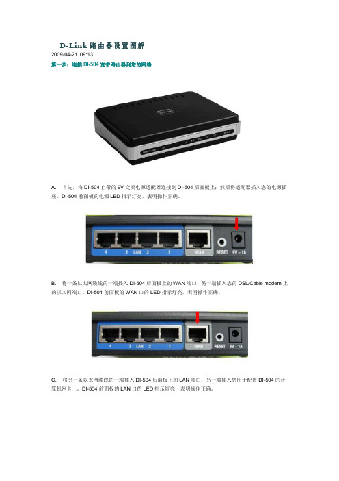
D-Link路由器设置图解2009-04-21 09:13第一步:连接DI-504宽带路由器到您的网络A.首先,将DI-504自带的9V交流电源适配器连接到DI-504后面板上;然后将适配器插入您的电源插座。
DI-504前面板的电源LED指示灯亮,表明操作正确。
B.将一条以太网缆线的一端插入DI-504后面板上的WAN端口,另一端插入您的DSL/Cable modem上的以太网端口。
DI-504前面板的WAN口的LED指示灯亮,表明操作正确。
C.将另一条以太网缆线的一端插入DI-504后面板上的LAN端口,另一端插入您用于配置DI-504的计算机网卡上。
DI-504前面板的LAN口的LED指示灯亮,表明操作正确。
注意:要复位系统设置为工厂设置,请遵照以下步骤:1. 不要断开DI-504宽带路由器的电源,2. 用曲别针按下reset 按钮并保持5 秒钟,3. 放开按钮DI-504 将自动重启。
(备注: 若按住少于五秒钟, DI-504 仅会重新激活, 而不能恢复设置为工厂设置)第二步:连接其他计算机到DI-504宽带路由器用其他的以太网缆线,将需要通过DI-504宽带路由器上网的具有以太网接口的其他计算机连接到DI-504后面板上剩余的3个LAN端口上。
当您完成以上两步安装向导后,您所连接的网络拓扑图应与下图相似。
第三步:正确配置您计算机的网络设置A.在您正在使用的计算机桌面上,用鼠标右键点击网上邻居,选择“属性”。
B.在随后打开的窗口里,用鼠标右键点击网上邻居,选择“属性”。
C.在随后打开的窗口里,先选择Internet协议(TCP/IP),再用鼠标点击“属性”。
D.在随后打开的窗口里,输入IP地址:192.168.0.2;子网掩码:255.255.255.0;默认网关:192.168.0.1;DNS为当地电信的IP地址,以成都为例输入:61.139.2.69。
E.然后在开始菜单的运行框里输入ping 192.168.0.1 -t能得到如下图的结果,就说明您以上的配置正确。

D-Link 交换机设备二层功能快速配置手册友讯网络D-Link2012年4月目录1、生成树协议 (2)1)生成树概述 (2)2)组网图示: (2)3)CLI配置步骤: (3)2、多生成树MSTP (4)1)组网示意图: (5)2)CLI配置步骤: (5)3、VLAN功能配置 (8)1)基于端口的VLAN配置 (8)2)管理VLAN配置 (10)3)VLAN标记(VLAN Trunk)配置 (10)4)最大VLAN数量和可配置范围检验 (11)5)VLAN状态查看 (12)4、端口镜像配置 (15)1)配置镜像 (15)2)开启端口镜像功能 (15)3)查看端口镜像配置信息 (16)4)删除端口镜像配置 (16)5)关闭端口镜像功能 (16)5、环路检测配置 (18)1)基于端口的LBD (18)2)基于VLAN的LBD (21)6、组播IGMP Snooping配置 (24)1)查看igmp_snooping状态 (24)2)交换机全局启用/关闭igmp_snooping功能 (24)3)启用/关闭某个vlan的igmp_snooping状态 (25)4)配置实例: (25)7、端口带宽控制配置 (26)8、堆叠配置 (27)1)虚拟堆叠(SIM)配置及适用机型 (27)2)按机型描述物理堆叠配置及堆叠方法说明 (36)1、生成树协议1)生成树概述(1)标准生成树STP标准生成树(STP)协议可以在保持物理连接成环的情况下有效的消除网络中的环路,并实现网络链路冗余备份功能。
(2)快速生成树RSTP快速生成树协议(RSTP),该协议基于STP协议,但是对原有协议做了更加细致的修改和补充。
主要改进三点:–首先,STP并没有细致区分端口状态和端口角色。
网络协议的优劣往往取决于协议是否对各种情况加以细致区分。
–其次,STP算法是被动的算法,对网络是否已经达到收敛没有一种反馈机制。
–再次,STP的算法要求在稳定拓扑里,根桥主动发出BPDU而其他交换机进行中继,这样整个STP网络。
D-Link 交换机设备管理设置快速配置手册
友讯网络
D-Link
2012年10月
目录
1、Console管理模式 (2)
2、Telnet模式 (5)
3、WEB界面管理 (8)
D-Link交换机支持3种管理配置方法,分别是Console管理(命令行CLI方式)、Telnet配置(命令行CLI方式)和WEB界面(菜单图形方式)配置。
1、Console管理模式
使用交换机配置线连接交换机Console口和调试PC串口,使用Windows操作系统自带的【超级终端】仿真软件对交换机进行配置管理。
首先在“开始”——“程序”——“附件”——“通讯”中打开“超级终端”。
新建连接,输入名称,选择正确的连接端口。
设置端口属性,首先点击“还原默认值”,然后选择“每秒位数(B)”为“9600”:
点击“确定”后即可打开交换机Console口配置模式,初始用户名/密码为空,按回车即可。
2、Telnet模式
在远程调试交换机设备时,无法使用Console口进行连接,此时可以使用Telnet方式,通过网络远程管理设备。
首先确定交换机的IP 地址,初始默认值为空,无IP,可以通过Console来配置,包括交换机设备当前IP地址、Telnet是否开启等信息。
配置交换机IP
打开“命令提示符”界面
首先通过ping命令测试管理PC与交换机网络是否连通。
确定网络连通后,使用Telnet命令进行远程调试。
例如
!配置只允许192.168.0.0/255.255.0.0这个网段的地址通过telnet访问交换机
Dlink(config)#login-access-list telnet 192.168.0.1 0.0.255.255
3、WEB界面管理
部分用户对命令行CLI方式配置交换机方式比较陌生,可以使用WEB界面来配置交换机。
首先确认交换机IP地址和网络连通性,并确定WEB管理是否开启(具体参照Telnet管理部分)。
如果WEB管理未开启,可通过Console或者Telnet方式下执行enable web命令开启。
开启WEB管理命令截图
然后在浏览器中,输入交换机地址,以下截图交换机IP默认为:http://10.90.90.90。
输入用户名和密码,初始默认为admin,点击“确定”按钮。
即可打开交换机web管理界面。