励磁系统原理图
- 格式:pps
- 大小:2.15 MB
- 文档页数:67
发电机励磁系统原理及运行1.(发电机励磁系统图:)励磁系统构成及优缺点:励磁电源由励磁变引自发电机机端,通过可控硅整流元件直接控制发电机的励磁,这种励磁方式即为自并励可控硅整流励磁,其特点如下:(1)因采用可控硅整流器和无需考虑同轴励磁机时间常数的影响,故可获得较高的电压响应速度。
(2) 励磁变压器接到发电机端不受厂用电压的影响,但需起励电源。
(3)缺点:其一整流输出的直流顶值电压受发电机或电力系统短路故障形式和故障点远近的影响,缺乏足够的强励能力。
其二由于自并励可控硅整流励磁系统的发电机短路电流衰减较快,对发电机带延时的后备保护可靠动作不利。
为此,过流保护可采用电流启动记忆,由复合电压或低电压闭锁的延时保护。
2. 发电机励磁装置:(1) 励磁装置组成:并联励磁变、可控整流装置、励磁调节器、灭磁及转子过电压保护、起励回路。
(2) 并联励磁变压器:型号:SCLLB-1800KVA / 容量:1800kVA一次电压15.75KV 二次电压:0.6kv接线Y/△ -11••••• 自并励励磁系统的励磁变压器不设自动开关,只设有隔离刀闸。
励磁变装设过流保护,该保护动作引跳出口油开关及灭磁开关。
励磁变接在主变底压侧,不受系统及厂用电影响。
•(3) 可控硅整流回路:(整流回路原理图:)以单相半波整流电路为例说明可控硅整流电路的工作原理。
要使可控硅导通,必须在可控硅的阳极及控制极同时加正向电压,并且使流过可控硅的阳极电流大于它的维持电流。
当阳极加反响电压,或流过可控硅阳极的电流小于维持电流时,可控硅截止。
从可控硅承受正向电压开始,到可控硅导通为止,这一段区间为控制角。
改变控制角的大小,可调整可控硅输出电压的大小。
可控硅整流电路可输出连续可调的直流电压。
主整流器采用三相全控桥,2个功率柜并列运行。
整流元件采用晶闸管整流,•每个功率柜额定功率输出2000A。
整流柜为强迫风冷式。
风机设有主、备用电源,互为备用(•主、备用电源:均用机旁I II段电源)。


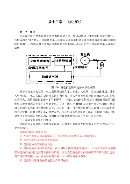
第十三章励磁系统第一节概述同步发电机的励磁控制系统是由励磁调节器、励磁功率单元和发电机组成的系统。
其构成如图13-1所示。
励磁功率单元是指向同步发电机转子绕组提供直流励磁电流的励磁电源部分,而励磁调节器则是根据控制要求和给定调节准则控制励磁功率单元输出的装置。
图13-1发电机励磁系统基本原理框图随着电力工业的发展,电力系统开始进入了大容量、大电网、高自动化时期。
对于大电网而言,电力系统的稳定性显得尤为重要,而大容量发电机短路比的减小及瞬变电抗的增大,均给系统稳定带来了不利影响。
因此,350MW机组对发电机励磁系统的顶值电压倍数和响应速度提出了更高要求。
目前,国内外350MW及以上容量发电机组主要采用无刷励磁方式和自并励励磁方式。
近年来,由于自并励励磁系统具有固有的高起始快速响应特性,而且接线简单,维护方便,加之电力系统稳定器(PSS)的配合使用,较好地解决了系统稳定性的问题,从而使自并励励磁系统得到了更为广泛的应用。
一、励磁系统的作用和要求励磁系统是发电机的重要组成部分,它对电力系统及发电机本身的安全稳定运行有很大的影响。
励磁系统的主要作用有:1)在电力系统正常运行情况下,维持发电机或系统某点电压水平。
2)合理分配发电机间的无功负荷。
3)提高电力系统的静态稳定。
4)提高电力系统的动态稳定。
在大容量长距离输电的电网中,采用自动调节励磁装置来提高系统的稳定性是方便和经济的,因此大型发电机上的励磁调节器的作用已超出调节电压的范围,所以称为励磁调节器,而不称为电压调节器。
5)提高带时限继电保护装置动作的灵敏度。
6)在暂态过程中(如故障切除后、个别发电机失磁时),能加速电网电压的恢复,提高电能质量,改善系统的工作条件。
励磁系统的要求:1)在正常运行时,能按照负荷电流和电压的变化,自动地改变励磁电流,以维持电压在给定值水平,并能稳定分配机组间的无功负荷。
2)应有足够的功率输出,在电力系统发生事故,电压降低时,能迅速地将发电机的励磁加大到最大值,以实现强行励磁的作用。
r i g h t 2002 A B B .t s r e s e r v e d . -1-5Close look of UNITROL ®5000 componentsABB (China) LtdMartin Affolterig ht202 AB B -2-UNITROL ®5000 –Content⏹Overview about components used in UNITROL ®5000⏹System in plant can be different from this presentationi g h t 2002 A B B -3-UNITROL ®5000 –Single line Diagrami g h t 2002 A B B -4-ig ht202 AB B -5-⏹Co ntroller B oard ⏹Central processor unit of UNITROL ®5000⏹Firmware and applicationi g h t 2002 A B B -6-ig ht202 AB B -7-⏹M easuring U nit B oard ⏹Measuring Ug and Ig ⏹Diode monitoring ⏹PSS (according IEEE)⏹PT-fail and other monitoring functionsi g h t 2002 A B B -8-ig ht202 AB B -9-⏹E xtended G ate C ontroller ⏹Backup current regulator ⏹Backup overcurrent relay Inverse time and instantaneous ⏹Backup thyristor branch monitoringi g h t 2002 A B B -10ig ht202 AB B -11⏹P ower S ignal I nterface ⏹Pre-processing of:⏹Synchronous voltage ⏹Field voltage ⏹AC field current ⏹DC field current (optional)i g h t 2002 A B B -12ig ht202 AB B -13⏹F ast I nput/O utput ⏹Interface between process signals and COB ⏹16 digital inputs ⏹18 digital outputs ⏹4 analog outputs ⏹3 analog inputs ⏹Input for crowbar current measurement ⏹3 amplifier inputs for current, voltage or resistance measurementi g h t 2002 A B B -14ig ht202 AB B -15⏹S ervice Pa nel ⏹Used for maintenance and servicei g h t 2002 A B B -16ig ht202 AB B -17⏹L ocal C ontrol P anel ⏹Display of analog values ⏹8 signals with name, value and unit ⏹4 signals with bar display ⏹Display of 8 error messages ⏹Plant specific keys with LEDig ht202 AB B -18⏹E xcitation C ontrol T erminal ⏹Different Screens ⏹Operation menu ⏹Power chart ⏹Single line diagram ⏹Trending ⏹Fault and event recorderi g h t 2002 A B B -19i g h t 2002 A B B -20⏹Pow er Supply and input filter ⏹Convert AC or DC power to 24Vdci g h t 2002 A B B -21i g h t 2002 A B B -22⏹F ield b us C oupler ⏹I/O interface via ARCnet ⏹32 digital inputs ⏹32 digital outputsi g h t 2002 A B B -23i g h t 2002 A B B -24⏹D igital I nput I nterface ⏹Used together with FBC ⏹16 galvanically isolated binary inputsi g h t 2002 A B B -25i g h t 2002 A B B -26⏹R elay O utput I nterface ⏹Used together with FBC ⏹16 relay outputsi g h t 2002 A B B -27ig ht202 AB B -28⏹D igital I nput / O utput ⏹Used together with FBC ⏹16 Digital inputs ⏹16 Digital outputs ⏹Input signals can be linked onto 2 trip channelsi g h t 2002 A B B -29ig ht202 AB B -30⏹A nalog I nput O utput ⏹I/O Interface via ARCnet ⏹8 analog inputs ⏹8 analog outputsi g h t 2002 A B B -31UNITROL ®5000 –Converterig ht202 AB B -32UNITROL ®5000 –Converter Bridge Thyristorsig ht202 AB B -33UNITROL ®5000 –Thyristor⏹3“ Flat Thyristors⏹1 Thyristor per branch→6 per converter bridge⏹Mounted between heatsinksig ht202 AB B -34UNITROL ®5000 –Converter Bridge ⏹Thyristors ⏹Branch fusesig ht202 AB B -35UNITROL ®5000 –Branch Fuse ⏹Disconnect branch in case of thyristor short circuit ⏹Enables redundancy, only faulty converter will be blocked ⏹Indication of blown fuseig ht202 AB B -36UNITROL ®5000 –Converter Bridge ⏹Thyristors ⏹Branch fuses ⏹Overvoltage protectionig ht202 AB B -37UNITROL ®5000 –Overvoltage protection ⏹AC voltage is connected via rectifier to R-C-filter ⏹Protect Thyristors from overvoltage ⏹Reduce commutation peaks ⏹Prevent self-firing of thyristors ⏹Capacitor ⏹Rectifier ⏹Resistors ⏹Fuseig ht202 AB B -38UNITROL ®5000 –Converter Bridge ⏹Thyristors ⏹Branch fuses ⏹Overvoltage protection ⏹Converter Isolatorig ht202 AB B -39UNITROL ®5000 –Convertor Isolator Disconnect bridge from power circuit (AC and DC) for maintenanceig ht202 AB B -40UNITROL ®5000 –Converter Bridge ⏹Thyristors ⏹Branch fuses ⏹Overvoltage protection ⏹Converter Isolator ⏹Cooling systemi g h t 2002 A B B -41UNITROL ®5000 –Fan box ⏹Cooling of converter ⏹Possibility of redundant fan ⏹Airflow monitoring with flaps ⏹Possibility of replacing single fani g h t 2002 A B B -42ig ht202 AB B -43⏹C onverter In terface ⏹Link between COB and GDI ⏹Current equalisation ⏹Conduction Monitoring ⏹Monitoring functions ⏹Branch current ⏹Temperature ⏹Status messages from Isolator ⏹Status messages from snubberi g h t 2002 A B B -44i g h t 2002 A B B -45⏹G ate D river I nterface ⏹Final pulse stage for thyristor bridgei g h t 2002 A B B -46ig ht202 AB B -47⏹C onverterD isplay P anel ⏹Display instantaneous converter current ⏹LED display for converter operating statusi g h t 2002 A B B -48ig ht202 AB B -49⏹Cu rrent S ensor ⏹Single-phase differential current measurement by means of a hall sensor ⏹Nominal current I N =2000Ai g h t 2002 A B B -50UNITROL ®5000 –Fieldbreaker。