A+K流量计算书中英文对照
- 格式:xls
- 大小:20.00 KB
- 文档页数:1

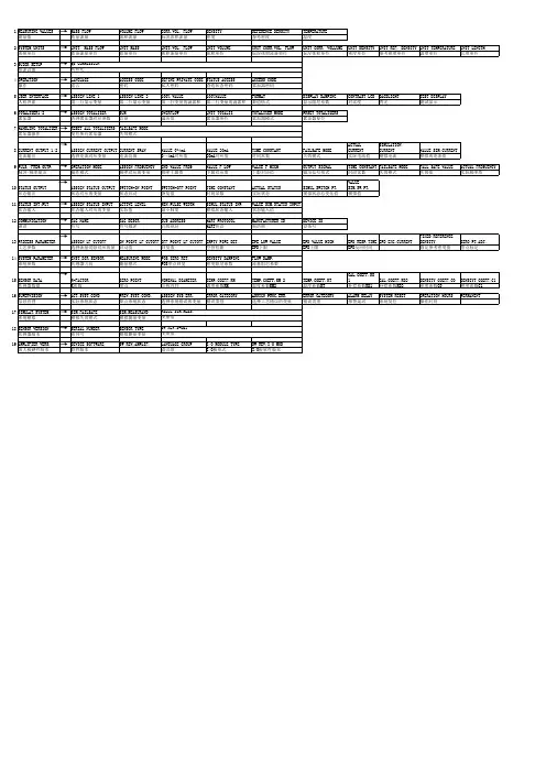
VehicleSpeed车辆速度EngineSpeed发动机转速CalculateLoad计算负荷VehicleLoad车辆荷载MassAirFlowSensor质量空气流量传感器AtmosphericPressure大气压力EngineOilTemperatureSensor发动机机油温度传感器CoolantTemperature冷却液温度IntakeAirTemperature进气温度IntakeAirTemperatureB1S1(Turbo)进气温度b1s1(涡轮)EngineRunTime发动机运行时间IG-ONCoolantTemperatureig-on冷却液温度InitialEngineCoolantTemperature初始发动机冷却液温度IG-ONIntakeAirTemperatureig-on进气温度InitialEngineIntakeAirTemperature发动机进气温度BatteryVoltage电池电压BATTVoltage电瓶电压EngineOilPressure发动机机油压力AcceleratorPosition加速器位置AcceleratorPositionSensorNo.1Voltage% 油门位置传感器1电压AcceleratorPositionSensorNo.2Voltage% 加速器位置传感器2电压% AcceleratorPositionSensorNo.1Voltage 油门位置传感器1号AcceleratorPositionSensorNo.2Voltage加速器位置传感器2电压AcceleratorPositionSensorNo.1FullyClosedLearnValue 油门位置传感器1号全封闭学习值AcceleratorPositionSensorNo.2FullyClosedLearnValue 油门位置传感器2号全封闭学习值EngineStartingTorqueControlCount发动机起动转矩控制计数ThrottlePositionSensorNo.1Voltage%节气门位置传感器1电压% ThrottlePositionSensorNo.2Voltage%节气门位置传感器SystemGuard系统防护OpenSideMalfunction开侧故障ThrottleRequestPosition节气门位置ThrottleSensorPosition节气门传感器位置ThrottlePositionSensorNo.1Voltage节气门位置传感器ThrottlePositionSensorNo.2Voltage节气门位置传感器ThrottlePositionCommand油门位置指令ThrottlePositionSensorOpenPositionNo.1节气门位置传感器开启位置1 ThrottlePositionSensorOpenPositionNo.2节气门位置传感器开启位置ThrottleMotorCurrent节气门电机电流ThrottleMotorDutyRatio节气门马达占空比ThrottleMotorDutyRatio(Open)节气门电机占空比(开)ThrottleMotorDutyRatio(Close)节气门电机占空比(近)ThrottlePositionSensorFullyClosedLearnValue节气门位置传感器全封闭学习值+BMVoltage+骨髓电压ActuatorPowerSupply执行器电源ThrottleAirFlowLearnValue(Area1)节流空气流量学习值(面积1)ThrottleAirFlowLearnValue(Area2)节流空气流量学习值(面积2)ThrottleAirFlowLearnValue(Area3)节流空气流量学习值(面积3)ThrottleAirFlowLearnValue(CalculatedValue)节流空气流量学习值(计算值)ThrottleAirFlowLearnValue(AtmospherePressureOffsetValue) 节流空气流量学习值(大气压力偏移值)WastegateValveControlDutyRatio废气旁通阀控制占空比LowRevolutionControl低转速控制NRangeStatus氮范围状态EngineStallControlF/BFlow发动机档位控制ISCF/BLearnTorqueISC的F/B学习扭矩ISCTotalAUXSTorqueISC总auxs扭矩ISCF/BTorqueISC的F/B扭矩SumofISCF/BTorque(Recent)和F/BISC扭矩(最近的)ISCAUXSTorque(Alternator)ISCauxs扭矩(发电机)ISCAUXSTorque(AirConditioner)ISCauxs扭矩(空调)ThrottleAirFlowF/BValue节气门空气流量TargetFuelPressure(High)目标燃油压力(高)TargetFuelPressure(Low)目标燃油压力(低)FuelPressure(High)燃油压力(高)FuelPressure(Low)燃油压力(低)FuelPumpControlDutyRatio燃油泵控制占空比InjectorCylinder#1(Port)注射器筒#1(港)InjectionVolumeCylinder#1注射量缸#1 TargetFuelPressureOffset目标燃油压力偏移InjectionVolume注入量LowFuelPressureSensor低燃油压力传感器FuelPressureTargetDischarge燃油压力目标放电FuelPressureDischarge燃油压力放电HighFuelPressureSensor高压燃油压力传感器HighPressureFuelPumpDutyRatio(D4) 高压燃油泵占空比(D4)HighPressureFuelPumpDischargeRate 高压燃油泵流量InjectionMode注入方式InjectionSwitchingStatus注入切换状态InjectionTimingCylinder#1(D4)喷油定时气缸#1(D4)InjectionTimeCylinder#1(D4)注射时间缸#1(D4)CurrentFuelType当前燃料类型EVAP(Purge)VSVEVAPVSV(净化)TargetAir-FuelRatio目标空燃比A/F(O2)LambdaSensorB1S1A/F(O2)λ传感器b1sA/F(O2)SensorVoltageB1S1A/F(O2)传感器电压b1s1A/F(O2)SensorCurrentB1S1A/F(O2)传感器电流b1s1A/F(O2)SensorHeaterDutyRatioB1S1 A/F(O2)传感器加热器占空比b1s1 O2SensorVoltageB1S2氧传感器电压b1s2O2SensorImpedanceB1S2氧传感器的阻抗b1s2O2SensorHeaterB1S2氧传感器加热器b1s2O2SensorHeaterCurrentValueB1S2氧传感器加热器的电流值b1s2ShortFTBank1短尺1LongFTBank1长1英尺的银行TotalFTBank1金融总银行1FuelSystemStatusBank1燃油系统状态库1IgnitionTimingCylinder#1点火正时,气缸#1KnockF/BValue敲楼值KnockCorrectLearnValue正确的学习价值IdleSparkAdvanceControlCylinder#1怠速点火提前控制气缸#1 IdleSparkAdvanceControlCylinder#2怠速点火提前控制气缸#2 IdleSparkAdvanceControlCylinder#3怠速点火提前控制气缸#3 IdleSparkAdvanceControlCylinder#4怠速点火提前控制气缸#4 IntercoolerWaterPumpSpeed中间水泵转速IntercoolerWaterPump中冷器水泵MassAirFlowCircuit空气流量电路VVTAdvanceFailVVT提前失败IntakeVVTHoldCorrectLearnValueBank1(Area1) 进气VVT持有正确的学习价值银行1(1区)IntakeVVTHoldCorrectLearnValueBank1(Area2) 进气VVT持有正确的学习价值银行1(2区)IntakeVVTOCVControlDutyRatioBank1进气VVTOCV控制占空比银行1 ExhaustVVTOCVControlDutyRatioBank1排气VVTOCV控制占空比银行1 IntakeVVTTargetAngleBank1进气VVT目标角度银行1ExhaustVVTTargetAngleBank1排气VVT目标角度银行1TargetBoostPressure目标升压压力BoostPressureSensor增压压力传感器CatalystTemperatureB1S1催化剂温度b1s1CatalystTemperatureB1S2催化剂温度b1s2StarterSW起动软件NeutralPositionSW中立位置StopLightSW停止光ImmobiliserCommunication防盗通信TCTerminal终端MILONRunDistancemil运行距离RunningTimefromMILON运行时间从万美元TimeAfterDTCCleared在DTC清除时间DistancefromDTCCleared距离DTC清除WarmupCycleClearedDTC热身周期清除DTC DistanceTraveledfromLastBatteryCableDisconnect 从去年的电池电缆断开的距离IGOFFElapsedTime用过的时间TotalDistanceTraveled总距离IgnitionTriggerCount点火触发计数MisfireCountCylinder#1#1缸失火计数MisfireCountCylinder#2#2缸失火计数MisfireCountCylinder#3#3缸失火计数MisfireCountCylinder#4#4缸失火计数AllCylindersMisfireCount所有气缸失火计数MisfireRPM失火的转速MisfireLoad工作负荷MisfireMargin失火的边缘CatalystOTMisfireFuelCut催化剂不熄火断油CatalystOTMisfireFuelCutHistory催化剂OT失火燃料切断历史CatalystOTMisfireFuelCutCylinder#1 催化剂不停油气缸失火#1 CatalystOTMisfireFuelCutCylinder#2 催化剂不停油气缸失火#2 CatalystOTMisfireFuelCutCylinder#3 催化剂不停油气缸失火#3 CatalystOTMisfireFuelCutCylinder#4 催化剂不停油气缸失火#4 EngineSpeed(StarterOff)发动机转速(起动)StarterCount起动器计数RunDistanceofPreviousTrip上一次旅行的距离EngineStartingTime发动机起动时间EngineStartHesitation发动机起动犹豫LowRevolutionforEngineStart发动机起动低转速FuelCutElapsedTime燃油切断时间A/FLearnValueIdleBank1一个学习价值的空闲银行1A/FLearnValueLowBank1学习价值低的银行1A/FLearnValueMidNo.1Bank1一个学习价值中第一银行1A/FLearnValueMidNo.2Bank1一个学习价值中第二银行1A/FLearnValueHighBank1学习价值高的银行1A/FLearnValueLow(Dual)Bank1学习值低(双)银行1A/FLearnValueMid(Dual)No.1Bank1 学习价值中(双)第一银行1A/FLearnValueMid(Dual)No.2Bank1 学习价值中(双)第二银行1A/FLearnValueHigh(Dual)Bank1学习价值高(双)银行1 CompressionLeakageCount压缩泄漏计数RoughIdleStatus粗怠速状态PluralCylindersRoughIdle多缸粗怠速RoughIdleCylinder#1怠速气缸#1RoughIdleCylinder#2怠速气缸#2RoughIdleCylinder#3怠速气缸#3RoughIdleCylinder#4怠速气缸#4 CoolingFanDutyRatio冷却风机占空比BrakeOverrideSystem制动控制系统ImmobiliserFuelCutStatus防盗燃油切断状态ImmobiliserFuelCutHistory防盗燃油切断历史KeyUnlockSignal钥匙开锁信号EngineSpeedCylinder#1发动机转速#1缸EngineSpeedCylinder#2发动机转速#2缸EngineSpeedCylinder#3发动机转速#3缸EngineSpeedCylinder#4发动机转速#4缸AverageEngineSpeedofAllCylinder 平均发动机转速ReceivedMILfromECT从收到的MIL等OutputAxisSpeed输出轴转速NTSensorSpeed速度传感器ShiftSWStatus(PRange)转向西南状态(磷范围)ShiftSWStatus(RRange)转向西南状态(转)ShiftSWStatus(NRange)移软件状态(氮范围)ShiftSWStatus(N,PRange)转变西南状态(氮,磷的范围)SportShiftUpSW运动转换SportShiftDownSW运动下降ShiftSWStatus(SRange)转向西南状态(范围)SnowModeSW雪模式ShiftSWStatus(DRange)转向西南状态(三维)A/TOilTemperatureNo.1油温1号LockUpStatus锁定状态ShiftStatus移位状态Snowor2ndStartModeStatus雪或第二启动模式状态StopandStartSystemEngineStatus 停止和启动系统引擎状态AirBypassValveControl空气旁通阀控制。
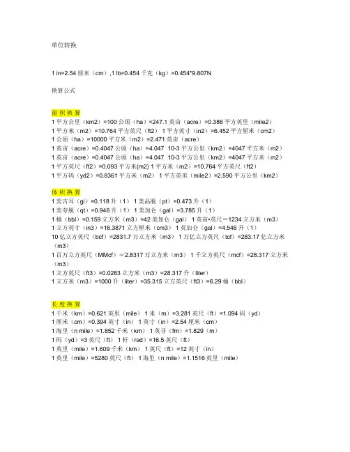
单位转换1 in=2.54厘米(cm),1 lb=0.454千克(kg)=0.454*9.807N换算公式面积换算1平方公里(km2)=100公顷(ha)=247.1英亩(acre)=0.386平方英里(mile2)1平方米(m2)=10.764平方英尺(ft2) 1平方英寸(in2)=6.452平方厘米(cm2)1公顷(ha)=10000平方米(m2)=2.471英亩(acre)1英亩(acre)=0.4047公顷(ha)=4.047×10⁻³平方公里(km2)=4047平方米(m2)1英亩(acre)=0.4047公顷(ha)=4.047×10⁻³平方公里(km2)=4047平方米(m2)1平方英尺(ft2)=0.093平方米(m2) 1平方米(m2)=10.764平方英尺(ft2)1平方码(yd2)=0.8361平方米(m2) 1平方英里(mile2)=2.590平方公里(km2)体积换算1美吉耳(gi)=0.118升(1) 1美品脱(pt)=0.473升(1)1美夸脱(qt)=0.946升(1) 1美加仑(gal)=3.785升(1)1桶(bbl)=0.159立方米(m3)=42美加仑(gal) 1英亩•英尺=1234立方米(m3)1立方英寸(in3)=16.3871立方厘米(cm3) 1英加仑(gal)=4.546升(1)10亿立方英尺(bcf)=2831.7万立方米(m3) 1万亿立方英尺(tcf)=283.17亿立方米(m3)1百万立方英尺(MMcf)=2.8317万立方米(m3) 1千立方英尺(mcf)=28.317立方米(m3)1立方英尺(ft3)=0.0283立方米(m3)=28.317升(liter)1立方米(m3)=1000升(liter)=35.315立方英尺(ft3)=6.29桶(bbl)长度换算1千米(km)=0.621英里(mile) 1米(m)=3.281英尺(ft)=1.094码(yd)1厘米(cm)=0.394英寸(in) 1英寸(in)=2.54厘米(cm)1海里(n mile)=1.852千米(km) 1英寻(fm)=1.829(m)1码(yd)=3英尺(ft) 1杆(rad)=16.5英尺(ft)1英里(mile)=1.609千米(km) 1英尺(ft)=12英寸(in)1英里(mile)=5280英尺(ft) 1海里(n mile)=1.1516英里(mile)质量换算1长吨(long ton)=1.016吨(t) 1千克(kg)=2.205磅(lb)1磅(lb)=0.454千克(kg)[常衡] 1盎司(oz)=28.350克(g)1短吨(sh.ton)=0.907吨(t)=2000磅(lb)1吨(t)=1000千克(kg)=2205磅(lb)=1.102短吨(sh.ton)=0.984长吨(long ton)密度换算1磅/英尺3(lb/ft3)=16.02千克/米3(kg/m3) API度=141.5/15.5℃时的比重-131.51磅/英加仑(lb/gal)=99.776千克/米3(kg/m3) 1波美密度(B)=140/15.5℃时的比重-1301磅/英寸3(lb/in3)=27679.9千克/米3(kg/m3) 1磅/美加仑(lb/gal)=119.826千克/米3(kg/m3)1磅/(石油)桶(lb/bbl)=2.853千克/米3(kg/m3)1千克/米3(kg/m3)=0.001克/厘米3(g/cm3)=0.0624磅/英尺3(lb/ft3)运动粘度换算1斯(St)=10-4米2/秒(m2/s)=1厘米2/秒(cm2/s)1英尺2/秒(ft2/s)=9.29030×10-2米2/秒(m2/s)1厘斯(cSt)=10-6米2/秒(m2/s)=1毫米2/秒(mm2/s)动力粘度换算动力粘度 1泊(P)=0.1帕•秒(Pa•s) 1厘泊(cP)=10-3帕•秒(Pa•s)1磅力秒/英尺2(lbf•s/ft2)=47.8803帕•秒(Pa•s)1千克力秒/米2(kgf•s、m2)=9.80665帕•秒(Pa•s)力换算1牛顿(N)=0.225磅力(lbf)=0.102千克力(kgf) 1千克力(kgf)=9.81牛(N)1磅力(lbf)=4.45牛顿(N) 1达因(dyn)=10-5牛顿(N)温度换算K=5/9(°F+459.67) K=℃+273.15 n℃=(5/9•n+32) °F n°F=[(n-32)×5/9]℃1°F=5/9℃(温度差)压力换算压力 1巴(bar)=105帕(Pa) 1达因/厘米2(dyn/cm2)=0.1帕(Pa)1托(Torr)=133.322帕(Pa) 1毫米汞柱(mmHg)=133.322帕(Pa)1毫米水柱(mmH2O)=9.80665帕(Pa) 1工程大气压=98.0665千帕(kPa)1千帕(kPa)=0.145磅力/英寸2(psi)=0.0102千克力/厘米2(kgf/cm2) =0.0098大气压(atm)1磅力/英寸2(psi)=6.895千帕(kPa)=0.0703千克力/厘米2(kg/cm2)=0.0689巴(bar)=0.068大气压(atm)1物理大气压(atm)=101.325千帕(kPa)=14.696磅/英寸2(psi)=1.0333巴(bar)传热系数换算1千卡/米2•时(kcal/m2•h)=1.16279瓦/米2(w/m2)1千卡/(米2•时•℃)〔1kcal/(m2•h•℃)〕=1.16279瓦/(米2•开尔文)〔w/(m2•K)〕1英热单位/(英尺2•时•°F)〔Btu/(ft2•h•°F)〕=5.67826瓦/(米2•开尔文)〔(w/m2•K)〕1米2•时•℃/千卡(m2•h•℃/kcal)=0.86000米2•开尔文/瓦(m2•K/W)热导率换算1千卡(米•时•℃)〔kcal/(m•h•℃)〕=1.16279瓦/(米•开尔文)〔W/(m•K)〕1英热单位/(英尺•时•°F)〔But/(ft•h•°F) =1.7303瓦/(米•开尔文)〔W/(m•K)〕比容热换算1千卡/(千克•℃)〔kcal/(kg•℃)〕=1英热单位/(磅•°F)〔Btu/(lb•°F)〕=4186.8焦耳/(千克•开尔文)〔J/(kg•K)〕热功换算1卡(cal)=4.1868焦耳(J) 1大卡=4186.75焦耳(J) 1千克力米(kgf•m)=9.80665焦耳(J)1英热单位(Btu)=1055.06焦耳(J) 1千瓦小时(kW•h)=3.6×10⁶焦耳(J)1米制马力小时(hp•h)=2.64779×10⁶焦耳(J) 1英尺磅力(ft•lbf)=1.35582焦耳(J)1英马力小时(UKHp•h)=2.68452×10⁶焦耳1焦耳=0.10204千克•米=2.778×10⁻⁷千瓦•小时=3.777×10⁻⁷公制马力小时=3.723×10⁻⁷英制马力小时=2.389×10⁻⁴千卡=9.48×10⁻⁴英热单位功率换算1英热单位/时(Btu/h)=0.293071瓦(W) 1千克力•米/秒(kgf•m/s)=9.80665瓦(w)1卡/秒(cal/s)=4.1868瓦(W) 1米制马力(hp)=735.499瓦(W)速度换算1英里/时(mile/h)=0.44704米/秒(m/s) 1英尺/秒(ft/s)=0.3048米/秒(m/s)渗透率换算1达西=1000毫达西 1平方厘米(cm2)=9.81×10⁷达西地温梯度换算1°F/100英尺=1.8℃/100米(℃/m)1℃/公里=2.9°F/英里(°F/mile)=0.055°F/100英尺(°F/ft)油气产量换算1桶(bbl)=0.14吨(t)(原油,全球平均)1万亿立方英尺/日(tcfd) =283.2亿立方米/日(m3/d)=10.336万亿立方米/年(m3/a)10亿立方英尺/日(bcfd)=0.2832亿立方米/日(m3/d) =103.36亿立方米/年(m3/a)1百万立方英尺/日(MMcfd)=2.832万立方米/日(m3/d)=1033.55万立方米/年(m3/a)1千立方英尺/日(Mcfd)=28.32立方米/日(m3/d)=1.0336万立米/年(m3/a)1桶/日(bpd)=50吨/年(t/a)(原油,全球平均)1吨(t)=7.3桶(bbl)(原油,全球平均)气油比换算1立方英尺/桶(cuft/bbl)=0.2067立方米/吨(m3/t)热值换算1桶原油=5.8×106英热单位(Btu) 1吨煤=2.406×10⁷英热单位(Btu)1立方米湿气=3.909×10⁴英热单位(Btu) 1千瓦小时水电=1.0235×10⁴英热(Btu)1立方米干气=3.577×10⁴英热单位(Btu)(以上为1990年美国平均热值)热当量换算1桶原油=5800立方英尺天然气(按平均热值计算) 1立方米天然气=1.3300千克标准煤1千克原油=1.4286千克标准煤◆容积单位换算表公升Liter 公秉Kiloliter 美制加仑U.S.Gallon 英制加仑Imp.Gallon 美桶Barrel 立方寸Cubic Feet 立方尺◆重量单位换算表Kilogram 公吨Metric ton 磅Pound 短吨Short ton 长吨1市斤=0.5000公斤=1.1023磅◆长度单位换算表公里km 公尺m 公分cm 公厘mm 公寸in 英尺ft 英里mile1(英海)=1.150776英里=6076英尺=1.852公尺,1市尺=1.0936英尺◆面积单位换算表平方公尺m2 平方寸in2 平方尺ft2 英亩acre 平方英里sq-mile 平方公分cm2 平方公厘mm21公顷=100公亩=10.000平方公尺=2.471英亩=1.0310里 1里=96.99194公亩=2.3967英亩=2.934坪◆主要力量单位换算表(国际标准单位与公制单位壶算)力量名称国际单位-公制单位公制单位-国际单位空气压力 1MPa=10.2kgf/cm2 1kgf/cm2=0.098MPa荷重力1N•m=0.102kgf•m 1kgf=9.8N扭力1N •m=0.102kgf 1kgf•m=9.8N•m真空压力 -1KPa=-7.5mmHg -1mmHg=-0.133KPa惯性力距1Kg•m2=10.2kgf•cm•s 1kg•cm•s=0.098Kgf•m2◆压力单位换算表◆流量单位换算表◆容积单位换算表◆重量单位换算表◆长度单位换算表◆面积单位换算表◆主要力量单位换算表(国际标准单位与公制单位壶算)常用中英对照数学 mathematics, maths(BrE), math(AmE)公理 axiom定理 theorem计算 calculation运算 operation证明 prove假设 hypothesis, hypotheses(pl.)命题 proposition算术 arithmetic加 plus(prep.), add(v.), addition(n.)被加数 augend, summand加数 addend和 sum减 minus(prep.), subtract(v.), subtraction(n.)被减数 minuend减数 subtrahend差 remainder乘 times(prep.), multiply(v.), multiplication(n.)被乘数 multiplicand, faciend乘数 multiplicator积 product除 divided by(prep.), divide(v.), division(n.)被除数 dividend除数 divisor商 quotient等于 equals, is equal to, is equivalent to大于 is greater than小于 is lesser than大于等于 is equal or greater than小于等于 is equal or lesser than运算符 operator平均数mean算术平均数arithmatic mean几何平均数geometric mean n个数之积的n次方根倒数(reciprocal) x的倒数为1/x有理数 rational number无理数 irrational number实数 real number虚数 imaginary number数字 digit数 number自然数 natural number整数 integer小数 decimal小数点 decimal point分数 fraction分子 numerator分母 denominator比 ratio正 positive负 negative零 null, zero, nought, nil十进制 decimal system二进制 binary system十六进制 hexadecimal system权 weight, significance进位 carry截尾 truncation四舍五入 round下舍入 round down上舍入 round up有效数字 significant digit无效数字 insignificant digit代数 algebra公式 formula, formulae(pl.)单项式 monomial多项式 polynomial, multinomial系数 coefficient未知数 unknown, x-factor, y-factor, z-factor 等式,方程式 equation一次方程 simple equation二次方程 quadratic equation三次方程 cubic equation四次方程 quartic equation不等式 inequation阶乘 factorial对数 logarithm指数,幂 exponent乘方 power二次方,平方 square三次方,立方 cube四次方 the power of four, the fourth power n次方 the power of n, the nth power开方 evolution, extraction二次方根,平方根 square root三次方根,立方根 cube root四次方根 the root of four, the fourth root n次方根 the root of n, the nth rootsqrt(2)=1.414sqrt(3)=1.732sqrt(5)=2.236常量 constant变量 variable坐标系 coordinates坐标轴 x-axis, y-axis, z-axis横坐标 x-coordinate纵坐标 y-coordinate原点 origin象限quadrant截距(有正负之分)intercede(方程的)解solution几何geometry点 point线 line面 plane体 solid线段 segment射线 radial平行 parallel相交 intersect角 angle角度 degree弧度 radian锐角 acute angle直角 right angle钝角 obtuse angle平角 straight angle周角 perigon边 side高 height三角形 triangle锐角三角形 acute triangle直角三角形 right triangle直角边 leg斜边 hypotenuse勾股定理 Pythagorean theorem 钝角三角形 obtuse triangle不等边三角形 scalene triangle 等腰三角形 isosceles triangle 等边三角形 equilateral triangle 四边形 quadrilateral平行四边形 parallelogram矩形 rectangle长 length宽 width周长 perimeter面积 area相似 similar全等 congruent三角 trigonometry正弦 sine余弦 cosine正切 tangent余切 cotangent正割 secant余割 cosecant反正弦 arc sine反余弦 arc cosine反正切 arc tangent反余切 arc cotangent反正割 arc secant反余割 arc cosecant补充:集合aggregate元素 element空集 void子集 subset交集 intersection补集 complement映射 mapping函数 function定义域 domain, field of definition 值域 range单调性 monotonicity奇偶性 parity周期性 periodicity图象 image数列,级数 series微积分 calculus微分 differential导数 derivative极限 limit无穷大 infinite(a.) infinity(n.)无穷小 infinitesimal积分 integral定积分 definite integral不定积分 indefinite integral复数 complex number矩阵 matrix行列式 determinant圆 circle圆心 centre(BrE), center(AmE) 半径 radius直径 diameter圆周率 pi弧 arc半圆 semicircle扇形 sector环 ring椭圆 ellipse圆周 circumference轨迹 locus, loca(pl.)平行六面体 parallelepiped立方体 cube七面体 heptahedron八面体 octahedron九面体 enneahedron十面体 decahedron十一面体 hendecahedron十二面体 dodecahedron二十面体 icosahedron多面体 polyhedron旋转 rotation轴 axis球 sphere半球 hemisphere底面 undersurface表面积 surface area体积 volume空间 space双曲线 hyperbola抛物线 parabola四面体 tetrahedron五面体 pentahedron六面体 hexahedron菱形 rhomb, rhombus, rhombi(pl.), diamond 正方形 square梯形 trapezoid直角梯形 right trapezoid等腰梯形 isosceles trapezoid五边形 pentagon六边形 hexagon七边形 heptagon八边形 octagon九边形 enneagon十边形 decagon十一边形 hendecagon十二边形 dodecagon多边形 polygon正多边形 equilateral polygon相位 phase周期 period振幅 amplitude内心 incentre(BrE), incenter(AmE)外心 excentre(BrE), excenter(AmE)旁心 escentre(BrE), escenter(AmE)垂心 orthocentre(BrE), orthocenter(AmE)重心 barycentre(BrE), barycenter(AmE)内切圆 inscribed circle外切圆 circumcircle统计 statistics平均数 average加权平均数 weighted average方差 variance标准差 root-mean-square deviation, standard deviation 比例 propotion百分比 percent百分点 percentage百分位数 percentile排列 permutation组合 combination概率,或然率 probability分布 distribution正态分布 normal distribution非正态分布 abnormal distribution图表 graph条形统计图 bar graph柱形统计图 histogram折线统计图 broken line graph曲线统计图 curve diagram扇形统计图 pie diagramabscissa 横坐标absolute value 绝对值acute angle 锐角adjacent angle 邻角addition 加algebra 代数altitude 高angle bisector 角平分线arc 弧area 面积arithmetic mean 算术平均值(总和除以总数)arithmetic progression 等差数列(等差级数)arm 直角三角形的股at 总计(乘法)average 平均值base 底be contained in 位于...上bisect 平分center 圆心chord 弦circle 圆形circumference 圆周长circumscribe 外切,外接clockwise 顺时针方向closest approximation 最相近似的combination 组合common divisor 公约数,公因子common factor 公因子complementary angles 余角(二角和为90度)composite number 合数(可被除1及本身以外其它的数整除)concentric circle 同心圆cone 圆锥(体积=1/3*pi*r*r*h)congruent 全等的consecutive integer 连续的整数coordinate 坐标的cost 成本counterclockwise 逆时针方向cube 1.立方数2.立方体(体积=a*a*a 表面积=6*a*a)cylinder 圆柱体decagon 十边形decimal 小数decimal point 小数点decreased 减少decrease to 减少到decrease by 减少了degree 角度define 1.定义 2.化简denominator 分母denote 代表,表示depreciation 折旧distance 距离distinct 不同的dividend 1. 被除数 2.红利divided evenly 被除数divisible 可整除的division 1.除 2.部分divisor 除数down payment 预付款,定金equation 方程equilateral triangle 等边三角形even number 偶数expression 表达exterior angle 外角face (立体图形的)某一面factor 因子fraction 1.分数 2.比例geometric mean 几何平均值(N个数的乘积再开N次方)geometric progression 等比数列(等比级数)have left 剩余height 高hexagon 六边形hypotenuse 斜边improper fraction 假分数increase 增加increase by 增加了increase to 增加到inscribe 内切,内接intercept 截距integer 整数interest rate 利率in terms of... 用...表达interior angle 内角intersect 相交irrational 无理数isosceles triangle 等腰三角形least common multiple 最小公倍数least possible value 最小可能的值leg 直角三角形的股length 长list price 标价margin 利润mark up 涨价mark down 降价maximum 最大值median, medium 中数(把数字按大小排列,若为奇数项,则中间那项就为中数,若为偶数项,则中间两项的算术平均值为中数。

电缆载流量计算书电缆有限公司技术部2019/9/211.载流量计算使用条件及必要系数:1. 导体交流电阻 R的计算R=R'(1+y s+y p)R'=R0[1+α20(θ-20)]其中:其中:对于分割导体ks=0.435。
其中:d c:导体直径 (mm)s:各导体轴心之间距离 (mm) 对于分割导体ks=0.37。
2.介质损耗W d的计算W d=ωCU02tgδ其中:ω=2πfC:电容 F/mU:对地电压(V)其中:εD i为绝缘外径 (mm)d c为内屏蔽外径 (mm)3.金属屏蔽损耗λ1的计算λ1=λ1'+λ1〃其中:λ1'为环流损耗λ1〃为涡流损耗λ1〃的计算:其中:ρ:金属护套电阻率 (Ω·m)R:金属护套电阻 (Ω/m)t:金属护套厚度 (mm)D oc:皱纹铝套最大外径 (mm) D it:皱纹铝套最小内径 (mm)a.三角形排列时2b.平行排列时1)中心电缆△2=03)外侧滞后相4.铠装损耗λ2的计算λ2=05热阻的计算5.1热阻T1的计算热阻式中:ρT1 — 绝缘材料热阻系数 (k·m/w)d c — 导体直径 (mm)t 1 — 导体和护套之间的绝缘厚度 (mm)5.2热阻T 2的计算 热阻T 2=05.3外护套热阻T 3的计算其中:t s -外护套厚度 ρT3-外护套(非金属)热阻系数5.4外部热阻T 4计算5.4.1空气中敷设其中:D e *:电缆外径 (mm)h: 散热系数当空气中敷设时,回路数对载流量基本没有影响。
5.4.2土壤中敷设5.4.2.1管道敷设,有水泥槽。
5.4.2.1.1电缆和管道之间的热阻T4′:其中:U、V和Y是与条件有关的常数。
D e 为电缆外径。
θm 为电缆与管道之间介质的平均温度。
5.4.2.1.2管道本身的热阻其中:D o 为管道外径。
D d 为管道内径。
ρT4为管道材料的热阻系数。
5.4.2.1.3管道外部热阻ρe 管道周围土壤的热阻系数。


#|段_Se ction__\r\n+|正的_pos itive__\r\n<|低于_<__\r\n<|小于_<__\r\n>|大于_>__\r\n0_SE Q|零序_zero_seque nce__\r\n1ST E XTR|一段抽汽_1st_ex tract ion__\r\n3 PH|全相_al l_pha ses__\r\nA_PW|有功功率_activ e_pow er__\r\nA BNM|异常_abn ormal__\r\nAC|交流_al terna ting_curre nt__\r\nA CCD|事故_acc ident__\r\nACK|确认_a cknow ledge__\r\nACT|动作_a ct__\r\nA CTIVE|激励_a ctive__\r\nADJ|调整_a djust ing__\r\nAIR|空气_Air__\r\nAIR FLOW|风量_A ir_fl ow__\r\nA IR_S|空侧_ai r_sid e__\r\nAL|漏风_A il_le ak__\r\nA LM|报警_alar m__\r\nAL M WIN|光字牌_alarm_wind ow__\r\nA PH|空预器_air_preh eater__\r\nARE A|分区_area__\r\nAREA|区_ar ea__\r\nA SH HO P|灰斗_ash_h opper__\r\nATM|雾化_a tomiz ing__\r\nATM R EL VL V|对空排汽门_at mosph eric_relie f_val ve__\r\n A UTO|自动_aut omati c__\r\nAU X|辅助_Auxil iary__\r\nAXIDISP|轴向位移_axial_disp lacem ent__\r\nBA|后_Back__\r\nBATT ERY|蓄电池_st orage_batt ery__\r\nBB|轴承箱_Bea ring_box__\r\nBBIN|筒体_bo bbin__\r\nBCHT Z|瓦斯_buchh oltz__\r\nBEAR|轴承_b earin g__\r\nBE AR VB RT|轴振_Bear ing_v ibrat ion__\r\nBELT|皮带_be lt__\r\nB FPT|小汽机_bo iler_feede r_wat er_pu mp_tu rbine__\r\nBFV|蝶阀_b utter fly_v alve__\r\nBH|在…的后面_behin d__\r\nBI G|PLT N_D__\r\nBIN|粉仓_bin,_pul veriz ed_co al_bu nker__\r\nBIN|煤粉仓_b in__\r\nB LDN|排污_Blo wdown__\r\nBLO CK|堵塞_bloc king__\r\nBLR|(锅)炉_boile r__\r\nBL R|锅炉_Boile r__\r\nBL R HAL L|锅炉房_boil er_ha ll__\r\nB NR|燃烧器_Bur ner__\r\nBODY|本体_bo dy__\r\nB OWL|磨碗_bow l__\r\nBO X|盒_b ox__\r\nB P|前置泵_boos ter_p ump__\r\nBRCH|分支_Br anch__\r\nBRCH|支路_b ranch__\r\nBRK R|断路器_brea ker__\r\nBRNHT|燃尽_b urnin g_exh aust__\r\nBTM|底_Bot tom__\r\nBUS|母线_bus__\r\nBUS H|轴瓦_Bush__\r\nBYPS|旁路_b ypass__\r\nCAB|柜_ca binet__\r\nCAB|机柜_C abine t__\r\nCA L|计算_calcu latio n__\r\nCA TION|阳离子_c ation__\r\nCCT|电路_C ircui t__\r\nCD|关命令_close_dema nd__\r\nC D|已关,关状态_C losed__\r\nCHA NL|通道_Chan nel__\r\nCHARG E|充电_Charg e__\r\nCH EM-WT R-X|化水变_Ch emist_wate r_xfm r__\r\nCH F|总_C hief__\r\nCHK|校正_Ch eck__\r\nCHK V|逆止门_check_valv e,_no n-ret urn_v alve__\r\n CIR|循环_ci rcula ting__\r\nCIRWTR|循环水_ci rcula ting_water__\r\nCL|闭式_cl osed__\r\nCL|关_clos e__\r\nCL CIRWTR|闭式循环水_close d_cir culat ing_w ater__\r\n CL S WTH|合闸_clo se_sw itch__\r\nCLCT|收集_C ollec tion__\r\nCLEA N|净_c lean__\r\nCLFR|粗粉分离器_cla ssifi er__\r\nC LG|冷却_cool ing__\r\nCLG A IR FA N|冷却风机_coo ling_air_(blowe r)_fa n__\r\n CL NG|顶棚_ceil ing__\r\nCLR|冷却器_co oler__\r\nCMPS|合成_c ompos e__\r\nCN D|凝结_conde nsate__\r\nCND P|凝结水泵_co ndens ate_p ump__\r\nCND W TR|凝结水_con densa ted_w ater__\r\nCNSR|凝汽器_conde nser__\r\nCNTR|连通管_conne ctor__\r\nCNVG|汇流_c onver ge__\r\nC OAL B LOCK|堵煤_co al_bl ockin g__\r\nCO AL CV R|输煤机_coal_conv eyer__\r\nCOAL FDR|给煤机_(coal_)_fee der__\r\nCOG|齿_cog__\r\nCOG|齿部_co g__\r\nCO IL|线圈_coil__\r\nCOL D AIR|冷风_c old_a ir__\r\nC OLLAR|轭部_c ollar__\r\nCOM|公用_C ommon__\r\nCOM BNR|组件_Com biner__\r\nCOM P|复合_Compl ex__\r\nC ONDT|导电度_c onduc tivit y__\r\nCO OL RH T|冷再热_cool_rehe at__\r\nC ORE|铁芯_(_i ron_\r\nC P|关状态_Clos ed_po sitio n__\r\nCP LR|耦合器_cou pler__\r\nCPRE SS AI R|压缩空气_com press ed_ai r__\r\nCR NR|角_corne r__\r\nCR RT|电流_curr ent__\r\nCRVC|夹层_cr evice__\r\nCRV C|间隙_crevi ce__\r\nC S|石子_Cobbl eston e__\r\nCS EP|细粉分离器_c yclon e_sep arato r__\r\nCS V|联合汽门_com bined_stea m_val ve__\r\nC TL|控制_Cont rol__\r\nCTL B OX|控制箱_con trol_box__\r\nCTL D MD|控制命令(对调节阀)_C ontro l_dem and__\r\nCTL R OOM|控制室_co ntrol_room__\r\nCTN BLDN|连排_c ontin ue_bl owdow n__\r\nCT N BLD N FLT K|连排扩容器_co ntinu e_blo wdown_flas htank__\r\n CTN R|罐_C ontai ner__\r\nCTR|中心_Cen ter__\r\nCV|用户阀_cus tomer_valv e__\r\nCX|公用变_commo n_tra nsfor mer__\r\nCYL|汽缸_cyl inder__\r\nDC|直流_di rect_curre nt__\r\nD EA|除氧器_dea erato r__\r\nDE MAG|消磁装置_d emagn etize r__\r\nDE MINE|除盐的_D emine raliz ed__\r\nD EMINR|除盐装置_Demi neral ized_devic e__\r\nDI F PRS(DP)|差压(压差)_dif feren tial_press ure__\r\nDIFF|差动_di ffere ntial__\r\nDIF F PRS|压差(差压)_di ffere ntial_pres sure__\r\nDIRT Y|脏_d irty__\r\nDISC H|泄放_Disch arge__\r\nDISC H OIL|放油_D ischa rge_o il__\r\nD ISCHSTM|放汽_Dis charg e_ste am__\r\nD ISCHWTR|放水_dis charg e_wat er__\r\nD ISCON|断线_d iscon necti ng__\r\nD ISP|位移_dis place__\r\nDMD|要求_D emand__\r\nDMD|指令,命令_Dem and__\r\nDMPR|挡板_da mper__\r\nDN|下_down__\r\nDNC MR|下降管_dow ncome r__\r\nDP HRM|隔膜_Dia phrag m__\r\nDR AFT|通风_Dra ft__\r\nD RG|渣_Dregs__\r\nDRN|疏水_d rain_water__\r\nDRN FLTK|疏水扩容器_dra in_wa ter_f lasht ank__\r\nDRN T K|疏水罐_drai n_tan k__\r\nDR N V|疏水阀_dr ain_w ater__\r\nDRUM|传动_d rum__\r\nDRUM|汽包_Dr um__\r\nD RV_E|驱动端_d rive_end__\r\nDSH|减温_Des uperh eat__\r\nDSHR|减温器_D esupe rheat er__\r\nD SL|柴油机_die sel_e ngine__\r\nDSP PR|消失_disa ppear__\r\nDSS LV|溶解_diss olved__\r\nDST Y|浓度_Densi ty__\r\nD TY OC|污油室_Dirty_oil_chamb er__\r\nD UP|复_Dupli cate__\r\nDWTR|脱水_D ewate r__\r\nDZ|刀闸_D ao_zh a__\r\nEC NT|偏心度_Ecc entri city__\r\nECON|省煤器_Econo mizer__\r\nEGF|排烟风机_exha ust_g as_fa n__\r\nEL EC|电气_Elec tric__\r\nEMG|紧急_Em ergen cy__\r\nE MG|事故_Emer gency__\r\nEMG RLVOIL V|紧急放油阀_eme rgenc y_rel ieve_oil_v alve__\r\n END|结束_en d__\r\nEN D FAC E|端_E nd_fa ce__\r\nE NST|蓄能器_en ergy_stora ge__\r\nE QPMNT|装置_e quipm ent__\r\nEXCHR|交换器_excha nger__\r\nEXCT|励磁_e xcita tion__\r\nEXCT R|励磁机_exci tator__\r\nEXC TR SI DE|励端_exci tator_side__\r\nEXH|排风_E xhaus t__\r\nEX H OIL|排油_E xhaus t_oil__\r\nEXH STM|排汽_Ex haust_stea m__\r\nEX H WTR|排水_E xhaus t_wat er__\r\nE XHR|排风机_Ex haust er__\r\nE XP|膨胀_expa nsion__\r\nEXP DIFF|胀差_e xpans ion_d iffer ence__\r\nEXTD|伸进_E xtend__\r\nEXT R|抽汽_extra ction_stea m__\r\nF/B|前后_front_\r\nFAIL|失败_f ailur e__\r\nFA ST CL|速断_f ast-c losin g__\r\nFA ULT|故障_Fau lt__\r\nF D|送风_force d_dra ft_ai r__\r\nFD BK|反馈_feed back__\r\nFDF|送风机_f orced_draf t_fan__\r\nFEE D WTR|给水_f eedwa ter__\r\nFGHT|消防_fi re_fi ghtin g__\r\nFI NE TR MT|精处理_fin e_tre atmen t__\r\nFI RING|有火_fi ring__\r\nFLAN|法兰_f lange__\r\nFLM|火焰_f lame__\r\nFLMINTS|火焰强度_flame_inte nsity__\r\nFLT K|扩容器_flas h_tan k__\r\nFL TR|过滤器_fil ter__\r\nFLTR|滤网_fi lter__\r\nFLUE GAS|排烟_fl ue_ga s__\r\nFL W|流量_flow__\r\nFNC|炉膛_fu rnace__\r\nFOR CE|强制_forc e__\r\nFP O|抗燃油_flam e_pro of_oi l__\r\nFR|前_fr ont__\r\nFREQ|频率_Fr equen cy__\r\nF UEL|燃料_Fue l__\r\nFU EL-X|燃油变_F uel_x fmr__\r\nFUSE|熔断_fu sible__\r\nFUS E|熔断器_fusi ble_c utout__\r\nFV|定值_Fi xed_v alue__\r\nGAS|气体_ga s__\r\nGA S|烟气_gas__\r\nGAS P ASS|烟道_gas_pass__\r\nGAS TEM|烟温_ga s_tem p__\r\nGD VN|导叶_guid e_van e__\r\nGE AR|齿轮_Gear__\r\nGEN|发电机_gener ator__\r\nGLD|汽封_st eam_s ealin g,_st eam_s eal_g land__\r\n GLD|轴封_Gl and__\r\nGND|接地_gro und__\r\nGP|组_Group__\r\nGVN|可调速的_gove rning__\r\nGVN OIL(GO)|调速油_Go verni ng_oi l__\r\nGV N V|调速汽门_g overn ing_v alve__\r\nGXU|发变组_g enera tor_t ransf ormer_unit__\r\nH2SPL|供氢_H2_suppl y__\r\nH2_S|氢侧_H2_s ide__\r\nHD_CP LR|液力耦合器_h ydrau lic_c ouple r__\r\n HD_MTR|油动机_h ydrau lic_s ervom otor__\r\n HDR|集箱_he ader__\r\nHDR|联箱_he ader__\r\nHDR|母管_he ader__\r\nHEAT STM|加热蒸汽_heat_steam__\r\nHEA VY|重_heavy__\r\nHES I|高能点火器_hi gh_en ergy_spark_igni tor__\r\nHIGHAUX|高辅_hig h_pre ssure_auxi liary__\r\nHIG H LMT|高限_h igh_l imit__\r\nHIGH PRS|高压力_h igh_p ressu re__\r\nH IGH S PD|高速_high_spee d__\r\nHI GH TE M|高温_high_tempe ratur e__\r\nHI GH VO LT|高电压_hig h_vol tage__\r\nHIGH(HI)|高_Hig h__\r\nHI PC|高中压缸_hi gh_in terme diate_pres sure_cylin der__\r\nHLWB|高位水箱_high_level_wate r_box__\r\nHMD T|湿度_humid ity__\r\nHORZ|水平(方向)的_ho rizon tal__\r\nHOT A IR|热风_hot_air__\r\nHOT R HT|热再热_hot_rehe at__\r\nH OT WE LL|热井_hot_well__\r\nHPC|高压缸_h igh_p ressu re_cy linde r__\r\nHP H|高加_high_press ure_h eader__\r\nHTG|采暖_H eatin g__\r\nHT R|加热器_heat er__\r\nH VSX|高备变_hi gh_vo ltage_stan dby_t ransf ormer__\r\nHYD L OIL|液压油_hydra ulic_oil__\r\nHYDP|液压_Hy draul ic_pr essur e__\r\nID A|引风_induc ed_dr aft_a ir__\r\nI DF|引风机_ind uced_draft_fan__\r\nIGNT|点火_I gniti on__\r\nI GNTR|点火器_I gnito r__\r\nIM PDC|阻抗_imp edanc e__\r\nIN C|增加_incre ate__\r\nIND W TR|工业水_ind ustri al_wa ter__\r\nING|进_Ingo ing__\r\nING L INE|进线_ing oing_line__\r\nINL|入口_in let__\r\nINL S IDE|吸入端_in let_s ide__\r\nINN|内,内侧,内部_inn er__\r\nI NT VO LT|问询电压_in terro gatio n_vol tage__\r\nINTM T|定期(排污)_i nterm itten t__\r\nIN TMT B LDN F LTK|定期排污扩容器_int ermit tent_blow_down_flash_tank__\r\n INT R PRS|中压_i nterm ediat e_pre ssure__\r\nINT RCT|联络_int ercon necti on__\r\nI NTRLK|联锁_i nterl ock__\r\nINVS|逆_inv erse__\r\nION|离子_io n__\r\nIP C|中压缸_inte rmedi ate_p ressu re_cy linde r__\r\n IS LN,IS LT|绝缘_Isol ation__\r\nISL T|隔离_isola te__\r\nI SLT P LTN|分隔屏_is olati ng_pl aten__\r\nJACK|顶轴_j ackin g__\r\nKW H|电度_elect rical_work__\r\nL_A|A层_L ayer_A__\r\nL_STG|末级_the_last_stag e__\r\nLA YER|层_laye r__\r\nLB TY SI DE|自由端_lib erty_side__\r\nLCL|就地_Lo cal__\r\nLE|左_Left__\r\nLEAK|泄漏_l eak__\r\nLIFT|支撑_li ft__\r\nL IFT B EAR|支撑轴承_l ift_b earin g__\r\nLI GHT|轻_ligh t__\r\nLM T|极限_Limit__\r\nLMT|限_li mit__\r\nLOAD|负荷_Lo ad__\r\nL OCK|闭锁_loc k__\r\nLO CK CL|闭锁关_lock_close__\r\nLOC K OPN|闭锁开_lock_open__\r\nLOSE MAG|失磁_lo se_ma gnet__\r\nLOSE SYN|失步_lo se_sy nchro nizer__\r\nLOW AUX|低辅_lo w_pre ssure_auxi liary__\r\n LOW FREQ|低频_l ow_fr equen cy__\r\nL OW LM T|低限_low_l imit__\r\nLOWPRS|低压力_lo w__\r\nLO W SPD|低速_l ow_sp eed__\r\nLOW T EM|低温_low_tempe ratur e__\r\nLO W VOL T|低电压_Low__\r\nLOW(LO)|低_Low__\r\nLPC|低压缸_l ow_pr essur e_cyl inder__\r\nLPH|低加_l ow_pr essur e_hea ter__\r\nLUB|润滑_lub e__\r\nLU B OIL|润滑油_lube_oil__\r\nLVL|液位_lev el__\r\nL WR|下层,低层_l ower__\r\nM_BL D|动叶片_movi ng_bl ade__\r\nMAG|电磁_ele ctric_magn etic__\r\nMAGV|电磁阀_elec tric_magne tic_v alve__\r\nMAIN|主_ma in__\r\nM AIN S TM|主蒸汽_mai n_ste am__\r\nM AIN S TM V|主汽门_m ain_s team_stop_valve__\r\nMAI N TUR B|主机_main_turbi ne__\r\nM AIN X FMR|主变_mai n_tra nsfor mer__\r\nMAINT ENACE|检修_m ainte nance__\r\nMAN L|手动_Manua l__\r\nMA TCH|满足_mat ch__\r\nM AX|最大_Maxi mum__\r\nMCH R M|机房_Machi ne_ro om__\r\nM CHN|机械_mec hanic al__\r\nM CM|磁控表_Mag netic_cont rol_m eter__\r\nMCR|最大持续功率_max imum_conti nuous_revo lutio n__\r\nMD FP|电动给水泵_m otor_drive_feed water_pump__\r\nMDS GOP|电动调速油泵_Moto r_dri ve_sp eed_g overn ing_o il_pu mp__\r\n M ESH|啮合_mes h__\r\nMF T|主燃料跳闸_ma ster_fuel_trip__\r\nMGNT|永励机_magne to_ge nerat or__\r\nM ID|中间,中部_M iddle__\r\nMIL L|磨煤机_coal_mill__\r\nMIN|最小_M inimu m__\r\nMK UP O IL|补油_make-up_o il__\r\nM K UPWTR|补水_mak e-up_water__\r\nMMT R|主电机_Main_elec tric_motor__\r\nMNT|力矩_M oment__\r\nMNT R|监视_monit or__\r\nM O|电动_motor_oper ated__\r\nMODE|方式_m ode__\r\nMOV|电动调节门_motor_oper ated_regul ating_valv e__\r\nMO V|电动门_moto r_ope rated_valv e__\r\nMS MNT P NT|测点_meas ureme nt_po int__\r\nMTL|金属_Met al__\r\nM TR|电机(电动机)_elec tric_motor__\r\nMTR|马达_m otor__\r\nMTV|动力_mo tive_power__\r\nN_D RV_E|非驱动端_non_d rive_end__\r\nN_SYM|不对称_non_s ymmet ry__\r\nN A|钠_n atriu m__\r\nNE T CTL ROOM|网控楼_netwo rk_co ntrol_room__\r\n NO.|号(量词)_Num ber__\r\nNODR|失灵_be_out_of_or der__\r\nNON|非_Non__\r\nNORM|正常_n ormal__\r\nNOZ ZLE|火嘴_Noz zle__\r\nN-SEQ|负序_n egati ve_se quenc e__\r\nNT RL PN T|中性点_Neut ral_p oint__\r\nO_PW|工作电源_oper ating_powe r__\r\nO2|氧_O2__\r\nO2CT|含氧量_oxy gen_c onten t__\r\nO2 CT|氧量_oxy gen_c onten t__\r\nOI L|油_o il__\r\nO IL BO X|油箱_Oil_b ox__\r\nO IL CL R|冷油器_oil_coole r__\r\nOI L FLT R|滤油器_oil_filte r__\r\nOI L P|油泵_oil_pump__\r\nOIL PIPE|油路_o il_pi pe__\r\nO IL PR S|油压_oil_p ressu re__\r\nO IL SP L|供油_oil_s upply__\r\nOIL STN|油站_oi l_sta tion__\r\nOILTEM|油温_oil_temp eratu re__\r\nO IL TK|贮油箱_oil_t ank__\r\nOIL V LU|油量_Oil_value__\r\nONL Y|仅_O nly__\r\nOPN|开式_ope n__\r\nOP N CIR|开式循环_open_circ ulati ng__\r\nO PN CI R WTR|开式循环水_ope n_cir culat ing_w ater__\r\n OPNDMD|打开命令_o pen_d emand__\r\nOPN ED|开状态_ope ned_s tatus__\r\nOPR|操作_o perat ion__\r\nORT|方向_ori entat ion__\r\nOUT|外部_out er__\r\nO UTG W IRE|出线_out going_wire__\r\nOUT G WTR|出水_O utgoi ng_wa ter__\r\nOUTL|出口_ou tlet__\r\nOUTL SIDE|吐出端_outle t_sid e__\r\nOV CRRT|过流_o ver_c urren t__\r\nOV EXCT R|过励磁_over_exci tator__\r\nOVLOAD|过负荷_o ver_l oad__\r\nOV LO AD|过载_over load__\r\nOV S PD|过速_over_spee d__\r\nOV VOLT|过压_o ver_v oltag e__\r\nOV ER SP D|超速_Over_speed__\r\nOVE R TEM|超温_o ver_t emper ature__\r\nOVF L|溢_o verfl ow__\r\nO VFL S TN|溢流站_ove rflow_stat ion__\r\nOX|工作变压器_o perat ing_t ransf ormer__\r\nP|负压_neg ative_pres sure__\r\nP_L_XFMR|厂低变_p lant_servi ce_lo wer_t ransf ormer__\r\n P_L_XFMR|厂高变_plant_serv ice_h igher_tran sform er__\r\n P_SHTR|屏式过热器_pla ten_s uperh eat__\r\nP_XFM R|厂变_plant_serv ice_t ransf ormer__\r\nPA|一次风_p rimar y_air__\r\nPAD|瓦(轴承)_pad__\r\nPAD|瓦块_p ad__\r\nP AF|一次风机_pr imary_air_fan__\r\nPAO|一次油_pr imary_oil__\r\nPB|按钮(键)_push_butto n__\r\nPC LVL|粉位_PC_leve l__\r\nPC E|排粉机_pulv erize d_coa l_exh auste r__\r\nPC S|制粉系统_Pul veriz ed-co al_sy stem__\r\nPCT|百分比_P ercen t__\r\nPH|相_ph ase__\r\nPH DI FF|相位差_pha se_an gle_d iffer ence__\r\nPH L OSE|缺相_pha se_lo se__\r\nP H MDF R|调相机_phas e_mod ifier,_pha se_mo dulat or__\r\n P IP|管,管道_Pi pe__\r\nP IP WA LL|管壁_Pipe_wall__\r\nPLN T|厂用_Plant__\r\nPLN T INN|厂内_p lant_inner__\r\nPLN T PWRATE|厂用电率_Plant_serv ice_p ower_rate__\r\n PLT|导向_pi lot__\r\nPLT B EAR|导向轴承_p ilot_beari ng__\r\nP LT V|滑阀_Pi lot_v alve__\r\nPLTN FAN|屏风机_p laten_fan__\r\nPMP(P)|泵_PUMP__\r\nPMT|允许_pe rmit__\r\nPNFC|盘面_p anel_face__\r\nPNMT C|气动_pneum atic__\r\nPNT|点_Poi nt__\r\nP OS|阀位/位置反馈_valv e_pos ition__\r\nPOS|位置_p ositi on__\r\nP RCT|保护_pro tecti on__\r\nP REC|除尘器_Pr ecipi tator__\r\nPRG C|程控_progr ammed_cont rol__\r\nPRHT|预热_pr eheat__\r\nPRH T PIP|预热管道_preh eat_p ipe__\r\nPROBE|探针_P robe__\r\nPRSREDRV|减压阀_pres sure_reduc er_va lve__\r\nPRS(P)|压力_press ure__\r\nPRS/T EM RE DR|减温减压器_t emper ature_and_press ure_r educe r__\r\n PU L|煤粉_Pulve rized_coal__\r\nPUL CVR|输粉机_p ulver ized_coal_conve yor__\r\nPULSE|脉冲_P ulse__\r\nPUROC|净油室_Pur ity_o il_ch amber__\r\nPUR GE|吹扫_purg e__\r\nPU RITY|纯度_pu rity__\r\nPUTI N|投_p uttin g_int o__\r\nPV L FDR|给粉机_pulve rized_coal_feed er__\r\nP W|电源_Power_supp ly__\r\nP W|功率_Power__\r\nPWON|有电_powe r_on__\r\nR_PW|无功_r eacti ve_po wer__\r\nRAD / AXI|径向_ra dial_/_axi al__\r\nR ATE|率_rate__\r\nRAT IO|比_Ratio__\r\nRB|快速减负荷_run_back__\r\nRBBR BALL|胶球_r ubber_ball__\r\nRBC H|消泡箱_ridd ing_b ubble_cham ber__\r\nRBEAR|径向轴承_Radi al_be aring__\r\nRCT F|整流的_rect ifyin g__\r\nRC TFR|整流器_re ctifi er__\r\nR EAR P LTN|后屏_rea r_pla ten__\r\nRECIR|再循环_recir culat e__\r\nRE CIR V|再循环阀_reci rcula ting_valve__\r\nRED R|减少_Reduc e__\r\nRE F|参考_refer ence__\r\nRELA Y|继电器_rela y__\r\nRE MO|遥控_Remo te__\r\nR ENEW|重新_re new__\r\nRETR|退回,缩回_retr act__\r\nRFF|回料风机_r eturn_fuel_fan__\r\nRGEN|再生_r egene ratio n__\r\nRG L STG|调节级_regul ating__\r\nRGL V|调节门_reg ulate_valv e__\r\nRH T|再热_Rehea t__\r\nRH T STM|再热蒸汽_rehe ated_steam__\r\nRHT R|再热器_rehe ater__\r\nRI|右_righ t__\r\nRL TV EX P|相对膨胀_rel ative_expa nsion__\r\nRMT|远方_r emote__\r\nROT SPD|转速_ro tatin g_spe ed__\r\nR OW|排(量词)_r ow__\r\nR RT|反转_reve rsal_rotat ion__\r\nRSET|复位_Re set__\r\nRT|正转_rota tion__\r\nRTN(OIL, WTR)|回(油,水)_re turn_(oil,_wate r)__\r\n R TN AI R|回送风_retu rn_ai r__\r\nRT R|转子_rotor__\r\nRUN|运行_R un__\r\nR UNP|运行状态_R unnin g_pos ition__\r\nRVR S|反向_rever se__\r\nR WG|反冲洗_Rev ersal_wash ing__\r\nS_A|A侧_sid e_A__\r\nS_BLD|静叶片_stati onary_blad e__\r\nSA|二次风_secon dary_air__\r\nSAD|二次风挡板_secon dary_air_d amper__\r\nSAH|暖风器_steam_air_heate r__\r\nSB W|吹灰_soot_blow__\r\nSBWR|吹灰器_soot_blowe r__\r\nSC|短路_S hort_circu it__\r\nS CHN|同步器,同操器_Syn chron izer__\r\nSCNR|火检_s canne r__\r\nSC ORE|比_scor e__\r\nSD|停止命令_stop_comm and__\r\nSDOP|汽动油泵_steam-driv en_oi l_pum p__\r\nSE AL|密封_Seal ing__\r\nSEALOIL|密封油_se al_oi l__\r\nSE AL WT R|密封水_seal_wate r__\r\nSE L|选择_selec t,_se lecti on__\r\nS EP|分离器_Sep arato r__\r\nSE T|设定_Set__\r\nSFT|安全_Saf ety__\r\nSFT|保安_saf ety__\r\nSGNL|信号_si gnal__\r\nSH|仓_Stor ehous e__\r\nSH|过热_s uperh eated__\r\nSHSTM|过热蒸汽_s uperh eated_stea m__\r\nSH ELL|壳体_she ll__\r\nS HFT|轴_Shaf t__\r\nSH KPRF|耐震_Sh ockpr oof__\r\nSHTR|过热器_s uperh eater__\r\nSID E|侧_S ide__\r\nSIDEWALL|侧墙_si de_wa ll__\r\nS LGRMV|出渣机,除渣机_s lag_r emove r__\r\nSL OT|槽_slot__\r\nSLOW DN|减速_slo w_dow n__\r\nSP|停止状态_stop_posi tion__\r\nSPD|速度_Sp eed__\r\nSPD G VNR|调速器_sp eed_g overn or__\r\nS PD UP|加速_s peed_up__\r\nS PRAY|喷水_sp ray__\r\nSRC|源_sour ce__\r\nS SPB|滑动止推轴承_Slid ing_s top_p ushin g_bea ring__\r\n SSR|传感器_S ensor__\r\nST|状态_st atus,_stat e__\r\nST AT|定子_stat or__\r\nS TBY|备用_sta ndby__\r\nSTBY PW|备用电源_s tandb y_pow er_so urce__\r\nSTEP UP|升压_ste p_up__\r\nSTG|级_Sta ge__\r\nS TG I|第一级_S tage_one__\r\nSTG I|一级_S tage_one__\r\nSTM|汽_Stea m__\r\nST M HDR|集汽联箱_stea m_hea der__\r\nSTM R OOM|蒸汽室_st eam_c hambe r__\r\nST M SPL|供汽_s team_suppl y__\r\nST M TEM|汽温_s team_tempe ratur e__\r\nST MLP|导汽管_st eam_l ead_p ipe__\r\nSTN|站_Stat ion__\r\nSTR|开始_sta rt__\r\nS TR|启动_star t__\r\nST RD|启动指令_St art_d emand__\r\nSTR OKE|行程_str oke__\r\nSURGE|喘震_s urge__\r\nSWAY|摆动_s way__\r\nSWTH|开关_sw itch__\r\nSWTH|切换_S witch__\r\nSYM|对称_s ymmet ry__\r\nS YNCH|同期_sy nchro nous__\r\nSYS|系统_sy stem__\r\nT V|三通阀_T_valv e__\r\nTA|三次风_terti ary_a ir__\r\nT AP|抽头_tap__\r\nTDFP|汽动给水泵_tur bine-drive n_fee dwate r_pum p__\r\n TE M(T)|温度_te mpera ture__\r\nTEST|检测_t est__\r\nTEST|试验_te st__\r\nT HRL|节流_Thr ottle__\r\nTHS T|推力_thrus t__\r\nTH ST BE AR|推力轴承_th rust_beari ng__\r\nT HTTL|截止_th rottl e__\r\nTO|至_to__\r\nTOINDCT|仪(器)用_to_indic ator__\r\nTOP|顶_top__\r\nTOR OSC|扭振_tor siona l_osc illat ion__\r\nTPLR|翻车机_t ipple r__\r\nTR IP|跳闸_trip__\r\nTRM T|处理_treat ment__\r\nTURB|(汽)机_turb ine__\r\nTURB|汽机_tu rbine__\r\nTUR B SID E|机端_turbi ne_si de__\r\nT URN|盘车_tur ning__\r\nTURN|匝间_t urn__\r\nTURNROOM|转向室_t urnin g_roo m__\r\nTV S|复速级_two-veloc ity_s tage__\r\nUNGE AR|脱扣_Unge aring__\r\nUNI T|机组_unit__\r\nUP|上,上部_u p__\r\nUP P|上层_upper__\r\nUSE|用(使用)_Use__\r\nUSE R|用户_User__\r\nV|阀门_valv e__\r\nVA CM|真空_Vacu um__\r\nV ACM B RK V|真空破坏阀_vacu um_br eak_v alve__\r\nVACM P|真空泵_vac uum_p ump__\r\nVBRT|振动_vi brati on__\r\nV ENT|排空_Ven t__\r\nVE RT|立式_vert ical_type__\r\nVERT|竖直(方向)的_v ertic al__\r\nV ICE|副_vice__\r\nVOL T|电压_volta ge__\r\nV OLT L OOP|电压回路_v oltag e_loo p__\r\nWA LL|墙_Wall__\r\nWALL TEM|壁温_wa ll_te mpera ture__\r\nWASH|清洗_w ash__\r\nWCL|有煤_wit h_coa l__\r\nWH L DAY|全天_w hole_day__\r\nWHL P LNT|全厂_who le_pl ant__\r\nWINDB OX|风箱_Wind box__\r\nWND|绕组_win ding__\r\nWNUT|磨损_w orn_o ut__\r\nW ORK|工作_wor king__\r\nWORK SHOP|厂房_Wo rksho p__\r\nWT R|水_w ater__\r\nWTRBOX|水箱_wat er_bo x__\r\nWT R CLC T|集水箱_wate r_col lecto r__\r\nWT R CUR TAIN|水幕_wa ter_c urtai n__\r\nWT R CUT|断水_c ut_of f_the_wate r_sup ply__\r\nWTR L VL|水位_wate r_lev el__\r\nW TR P|水泵_Wa ter_p ump__\r\nWTR S EAL|水封_Wat er_se al__\r\nW TR SP L|上水_water-supp ly__\r\nW TR TR MT|水处理_wat er_tr eatme nt__\r\nW TR WA LL|水冷壁_wat er_wa ll__\r\nX FMR|变压器_tr ansfo rmer__\r\nXPRT|输送_t ransp ort__\r\n02-DL-MU|#2机220V直流系统→#2机220V直流动力母线电压→\r\n02-KZ-MU|#2机220V直流系统→#2机220V直流控制母线电压→\r\nS E1-2F-A1|#2发-变组系统→#2发电机定子电流 A→#2 GE N STA T CRR T A\r\n SE1-2F-A2|#2发-变组系统→#2发电机定子电流B→#2 GEN STAT CRRT B\r\n SE1-2F-A3|#2发-变组系统→#2发电机定子电流C→#2 GENSTATCRRTC\r\n SE1-2F-A4|#2发-变组系统→#2发电机负序电流→#2 GE N N-SEQ C RRT\r\nSE1-2F-V1|#2发-变组系统→#2发电机定子三相电压AB→#2 GENSTATT-PHVOLTAB\r\nSE1-2F-V2|#2发-变组系统→#2发电机定子三相电压 BC→#2 G EN ST AT T-PHVO LT BC\r\nSE1-2F-V3|#2发-变组系统→#2发电机定子三相电压CA→#2 GEN STAT T-PH VOLT CA\r\nSE1-2F-V5|#2发-变组系统→#2发电机定子绝缘电压A相→#2 G EN ST AT IS LNVO LT A-PH\r\nSE1-2F-V6|#2发-变组系统→#2发电机定子绝缘电压B相→#2 GE N STA T ISL N VOL T B-P H\r\nSE1-2F-V7|#2发-变组系统→#2发电机定子绝缘电压C相→#2 GEN STAT ISLN VOLT C-PH\r\nSE1-2F-H1|#2发-变组系统→#2发电机频率→#2GEN F REQ\r\nSE1-2F-H2|#2发-变组系统→220KV南母频率→220KV S YS F REQ\r\nSE1-2F-H3|#2发-变组系统→220KV北母频率→220KV S YS F REQ\r\nSE1-2F-W|#2发-变组系统→#2发电机有功功率→#2 G EN A-PW\r\nSE1-2F-V a|#2发-变组系统→#2发电机无功功率→#2 G EN R-PW \r\nSE1-2F-COS|#2发-变组系统→#2发电机功率因数(DC S计算实现)→#2GEN P W COS\r\nSE1-2FB-V1|#2发-变组系统→220 k V南母母线电压→220KVS-BUS VOLT\r\nSE1-2FB-V2|#2发-变组系统→220 k V 北母母线电压→220KV N-BU S VOL T\r\nSE1-2EX-1ZA|#2发-变组系统→#2发电机#1整流柜输出直流电流→#2 RCT F CAB OUTP DC C RRT\r\nSE1-2EX-2ZA|#2发-变组系统→#2发电机#2整流柜输出直流电流→#2 R CTF C AB OU TP DC CRRT\r\nSE1-2EX-A1|#2发-变组系统→#2发电机转子电流→#2 GE N RTR CRRT\r\nSE1-2EX-A3|#2发-变组系统→#2发电机主励转子电压→#2GEN M AIN E XCTRRTR V OLT\r\nSE1-2EX-A5|#2发-变组系统→#2发电机主励转子电流→#2 GE N MAI N EXC TRRT R CRR T\r\nSE1-2EX-V1|#2发-变组系统→#2发电机转子电压→#2 G EN RT R VOL T\r\nSE1-2EX-V2 |#2发-变组系统→#2发电机付励定子电压→#2 GEN VICE EXCT RST AT VO LT\r\nSE1-2EX-V3|#2发-变组系统→#2发电机转子正对地电压→#2 GE N RTR P-V S-GND VOLT\r\nSE1-2EX-V4|#2发-变组系统→#2发电机转子负对地电压→#2 GENRTR N-VS-G ND VO LT\r\nSE1-2EX-V6|#2发-变组系统→#2发电机功角(电压电势夹角)→#2 MAIN EXCTSTAT VOLT\r\nSE7-2GB-W|#2高厂变系统→#2高厂变有功功率→#2 P-H-XFMRA-PW\r\nSE7-2GB-VA R|#2高厂变系统→#2高厂变无功功率→#2 P-H-XFM R R-P W\r\nSE7-2GB-A1|#2高厂变系统→#2高厂变高压侧电流→#2 P-H-XF MR H-VOLTCRRT\r\nSE7-2GB-A2|#2高厂变系统→613开关电流→613 SWTH CRRT\r\nSE7-2GB-A3|#2高厂变系统→614开关电流→614 SWTH CRRT\r\nSE7-B FA-A1|#2高厂变系统→603开关电流→603 SWTH CRRT\r\nSE7-B FB-A1|#2高厂变系统→604开关电流→604 SWTH CRRT\r\nSE7-2GB-V1|#2高厂变系统→6 kV 3段母线电压→6 KV #3 B US VO LT\r\nSE7-2GB-V2|#2高厂变系统→6 kV 4段母线电压→6KV #4 BUSVOLT\r\nS E7-2G B-V5|#2高厂变系统→6kV 3段绝缘电压AN→6 KV #3 ISL T VOL T AN\r\n S E7-2G B-V6|#2高厂变系统→6kV 3段绝缘电压BN→6KV #3 ISLT VOLT BN\r\n SE7-2GB-V7|#2高厂变系统→6 k V 3 段绝缘电压CN→6KV #3 ISLT VOLT CN\r\n SE7-2GB-V8|#2高厂变系统→6 k V 4 段绝缘电压AN→6KV #4 ISLT VOLT AN \r\n S E7-2G B-V9|#2高厂变系统→6kV 4段绝缘电压BN→6KV #4 ISLT VOLT BN \r\n S E7-2G B-V10|#2高厂变系统→6 kV 4段绝缘电压 CN→6 KV#4 IS LT VO LT CN \r\n SE8-3DB-V|#2机低压厂用电系统→380V3段母线电压→380V #3 BUSVOLT\r\nS E8-4D B-V|#2机低压厂用电系统→380V4段母线电压→380V #4 B US VO LT\r\n SE8-3DB-A|#2机低压厂用电系统→#3低厂变高压侧电流→#3 P-L-XFMR H-VO LT S IDE C RRT\r\nSE8-4DB-A|#2机低压厂用电系统→#4低厂变高压侧电流→#4 P-L-XFM R H-V OLT S IDE C RRT\r\nSG Y-1CH-A|#2机公用及备用系统→1除灰甲开关电流→\r\nSG Y-2CH-A|#2机公用及备用系统→2除灰甲开关电流→\r\nSE4-ZMB-A|#2机公用及备用系统→照明检修变高压侧电流→M-L-X HIGH VOLT SIDE CRRT\r\nSE4-Z MB-V|#2机公用及备用系统→照明检修段母线电压→M-L-X BUS VOLT\r\nSE5-02B-A|#2机公用及备用系统→#2低备变高压侧电流→#2 LVSX H-V SIDE CRRT\r\nSE5-02B-V|#2机公用及备用系统→380V备2段母线电压→380V ST BY #2 BUSVOLT\r\nS E1-2F B-R1|#2发-变组系统→#2主变油温1→#2 MAIN XFMR OILTEM 1\r\nSE7-2GB-R1|#2高厂变系统→#2高厂变温度→#2P-H-X FMR T EM\r\nSE8-3DB-R1|#2机低压厂用电系统→#3低厂变温度→#3P-L-X FMR T EM\r\nSE1-2FB-R2|#2发-变组系统→#2主变油温2→#2 MA IN XF MR OI L TEM 2\r\nSE8-4DB-R1|#2机低压厂用电系统→#4低厂变温度→#4P-L-X FMR T EM\r\nSE4-ZMB-R1|#2机公用及备用系统→照明检修变温度→M-L-X TE M\r\nSE5-02B-R1|#2机公用及备用系统→#2低备变温度→#2 L VSX T EM\r\nSE1-2GLB-F1|#2发-变组系统→#2发变组故障录波器装置故障→#2GXU F AUILRECOR D EQP FAIL\r\nSE1-2GLB-F2|#2发-变组系统→#2发变组故障录波器动作→#2GXUFAUILRECO RD AC T\r\nSE1-2GLB-F3|#2发-变组系统→#2发变组故障录波器电源消失→#2G XUFA UIL R ECORD PW D ISPPR\r\nE14-172-EL CERR|#2发-变组系统→Y222开关跳闸→Y222 SW TH TR IP\r\nE14-036-ELCER R|#2发-变组系统→#2发电机灭磁开关跳闸→#2GEN M K SWY H TRI P\r\n。
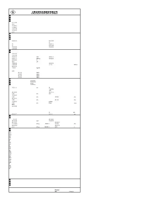
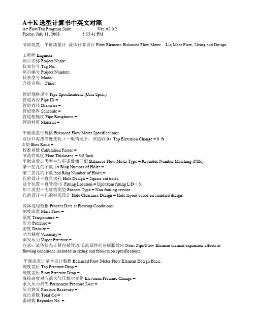
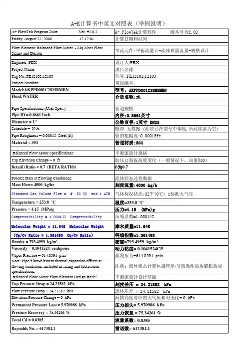
A+K选型计算书中英文对照A+ FlowTek Program Suite Ver. #2.0.2Friday, July 11, 2008 3:55:41 PM______________节流装置:平衡流量计- 流体计算设计Flow Element: Balanced Flow Meter - Liq Mass Flow, Sizing and Design ______________工程师Engineer:项目名称Project Name:仪表位号Tag No.:项目编号Project Number:仪表型号Model:介质名称: Fluid:______________管道规格说明Pipe Specifications:(User Spec:)管道内径Pipe ID =管道直径Diameter =管道壁厚Schedule =管道粗糙度Pipe Roughness =管道材质Material =______________平衡流量计规格Balanced Flow Meter Specifications:取压口海拔高度变化(一般情况下,该值取0)Tap Elevation Change = 0 ftß值Beta Ratio =校准系数Calibration Factor =节流件厚度Plate Thickness = 3/8 Inch平衡流量计类型=与雷诺数相匹配Balanced Flow Meter Type = Reynolds Number Matching (NRe)第一层孔的个数1st Ring Number of Holes =第二层孔的个数2nd Ring Number of Holes =孔的设计=直角切孔Hole Design = Square cut holes.适合位置=直管段>5 Fitting Location = Upstream fitting L/D > 5.加工类型=无脏物类型Process Type = Non-fouling service.孔的设计=孔的标准设计Hole Clearance Design = Hole layout based on standard design.______________流体过程数据Process Data at Flowing Conditions:刻度流量Mass Flow =温度Temperature =压力Pressure =密度Density =动力粘度Viscosity =蒸发压力Vapor Pressure =注意:流体状态计算包括管道/节流原件的热膨胀效应Note: Pipe/Flow-Element thermal expansion effects at flowing conditions included in sizing and fabrication specifications.______________平衡流量计基本设计数据Balanced Flow Meter Flow Element Design Basis:刻度差压Tap Pressure Drop =刻度差压Flow Pressure Drop =海拔高度对应的大气压相对变化Elevation Pressure Change =永久压力损失Permanent Pressure Loss =压力恢复Pressure Recovery =流出系数Total Cd =雷诺数Reynolds No. =。
ACCURATE CALCULATION OF PIPELINE TRANSPORT CAPACITYLeif Idar Langelandsvik 1, Willy Postvoll1, Britt Aarhus1, Kristin Kinn Kaste11. Gassco ASKeywords: 1. natural gas; 2. pipeline capacity; 3. friction; 4. ambient temperature, 5. operational data1 AbstractGassco is the operator of the largest sub-sea transportation system for natural gas in the world. This implies selling transport capacity to shippers of natural gas. Once a pipeline is built, the physical capacity is determined by boundary conditions such as available inlet and outlet pressure. In order to achieve optimal utilization of the pipelines and hence optimal return of invested capital, it is of great importance to calculate this capacity as accurately as possible. Failing to meet booked capacities will result in penalties and poorer reputation while under estimation of the capacity can possibly trigger too early investments in new infrastructure. Both situations are strongly unwanted. Gassco has therefore developed a well proven methodology for transport capacity calculation, which will be elaborated in this paper.Over the last years Gassco has improved the former approach of capacity calculation, namely a capacity test. This improvement has involved further development of the models, particularly by means of heat transfer, which now makes the models more accurate than before and even better suited to calculate transport capacity. Incorporation of real-time modelled sea-bottom temperatures from the UK Meteorological Shelf-seas model provides the models with the best available now-casts and two-day-forecasts of the sea- bottom temperature across most of the North Sea. Better estimates of actual sea-bottom temperatures on certain days in the past combined with short-term forecasts updated every day reduce margins and utilize day-to-day variations in capacity induced by the ambient temperature. Eventually instead of using one single capacity-test point, Gassco has now extended this methodology to make use of steady-state operational data periods in the past, which one-by-one is treated like a capacity test. The results are then averaged to reduce the random error uncertainty in the estimate.Basically these measures have increased the accuracy of the transport capacity calculations. It is however also seen that the result is increased transport capacity which can be sold to the shippers. Altogether the methodology outlined in this paper probably represents the best practice in gas industry with respect to transport capacity calculation. The benefit is increased capacity and consequently flexibility for the shippers, increased income for the infrastructure owners and reduced unit tariff for the shippers.2 Introduction/BackgroundNatural gas plays an important role in the energy supply of Europe and the world. Natural gas accounts for almost a quarter of worl d’s energy consumption. According to energy statistics f rom , total world production in 2008 was 3,065 billion cubic meters, i.e. 3.1·1012 MSm3, of which Norway contributed 3.2% (99.2 billion Sm3). Natural gas is mainly transported in pipelines, either onshore or offshore.The Norwegian gas transportation system is illustrated in Figure 1 and consists of 7,800 km of pipelines, processing plants, riser platforms and receiving terminals, yielding a very complex network which is the largest offshore transportation system in the world. United Kingdom and continental Europe are supplied through seven large diameter subsea pipelines covering around 15% of the European natural gas consumption. The export pipelines are between 500 and 800 km long with a typical inner diameter of 1 m. Security of supply for the customers requires reliable and optimal operation of the transport system.Figure 1 Overview of the trans portation system operated by Gassco.After a reorganization of the infrastructure on the Norwegian Continental Shelf in 2001, the state- owned company Gassco was appointed the operator of the transportation system. The ownership of the infrastructure is organized in a joint-venture, Gassled, where the different companies’ interest is determined based on their historical investments. Gassco is thus responsible for redelivering the requested amount ofgas at the different exit points. The shippers have a certain capacity right, a booked capacity, at each exit point. They can then nominate up to this amount of gas at each exit point, as long as they make the same amount of gas available at an entry point. The shipper may be a producer of gas, or it may have purchased the gas upstream the entry point. The capacity is sold as non-interruptable.Transportation capacity is made available for shippers in dedicated booking rounds, where capacity can be booked on long-term, medium-term or short-term. This will be elaborated later. The unit price of capacity is fixed and regulated by Norwegian government. All the capacity is sold at nearly all exit points, even though it is only fully exploited perhaps a few weeks during a year.High accuracy in the pipeline transport capacity calculations is of crucial importance in order to ensure optimal utilization of invested capital in the pipeline infrastructure. One wants the calculations to be as close to, but not larger than, the true capacity as possible. This will ensure optimal utilization of invested capital. As soon as a pipeline is built, the true capacity is determined by the diameter, length, available inlet compression, minimum delivery pressure and other physical parameters. In Gassco it is the job of scientists to estimate this figure exactly before the commercial department sells the capacity to the shippers. This paper explains the elaborate process used by Gassco to calculate an exact hydraulic capacity. A process that leads to a very accurate hydraulic capacity, and which has been used with great success.The Gassco operated pipelines are often single-leg with one supply point and one delivery point. Since the pipelines are sub-sea, instrumentation is also only found at the inlet and outlet. The methodology is therefore most elaborate for this kind of pipeline. Nonetheless, it also covers pipelines with branches.a. Capacity DefinitionsGassco uses several definitions for pipeline transport capacity. The hydraulic capacity is the calculated maximum physical throughput using maximum inlet pressure and minimum outlet pressure. Available Technical Capacity accounts for limitations in system boundary conditions, eg. caused by limited inlet pressure due to dependency with other pipelines. A fuel factor is also deducted to account for metering errors and fuel gas consumption in either compressors or heating stations. The committable capacity is the capacity that is available for stable deliveries. An operational flexibility (opflex) of 1 or 2 % is usually deducted from the available technical capacity to ensure that small operational disturbances do not lead to loss of delivered gas. Gassco has the mandate to hold back capacity for certain periods. When this hold back is deducted, the bookable capacity is obtained. This is the capacity that is offered to the shippers.b. Pipeline SimulatorsThe transport capacity of Gassco operated pipelines is calculated by using computer simulation models. A detailed model of the pipeline is implemented in a commercially available simulation software. The methodology described in this paper is independent of the chosen software, and should work equally well with most available pipeline simulation software packages. Great care is taken to ensure that all pipeline parameters such as pipeline length, diameter, thickness of different wall layers, elevation profile and burial depth on the sea bed are correct. After the pipeline is installed, the design data is combined with survey data to obtain the best possible data.The simulation software uses the Benedict-Webb-Ruben-Starling (BWRS) equation of state. Great effort has been put into tuning the coefficients to ensure it predicts the density of typical North Sea gases well. The predictive power of the viscosity correlation Lee-Gonzalez-Eakin (LGE) has also been analyzed. The correlation has a simple structure which makes it attractive for use in real-time systems. And it has also proved to predict viscosity for natural gas mixtures well. Gassco has initiated a measurement series of viscosity, and has also proposed a new set of coefficients for the LGE-correlation based on these measurements.The heat transfer model is important in order to simulate the gas temperature correctly. This will be discussed later in the paper.All pipeline simulators use a friction factor correlation which takes wall roughness as input, and calculates the friction factor which gives the wall friction in the model. One of the main uncertainties when modelling pipeline flow, is which roughness factor to use and how the friction shall be calculated based on it. This is also discussed below.c. InstrumentationIn order to achieve the desired accuracy of the transport capacity calculations, Gassco has put a lot of effort into the instrumentation of the pipelines. All pipelines are equipped with state-of-the-art flow meters and pressure transmitters at all supply and delivery points. The pressure transmitters usually have an absolute uncertainty of 52 mBar within a range of 0-200 barg or 0-400 barg depending on the application. The flow meters are either qualified as fiscal or have a similar uncertainty. Usually they are ultrasound⎧ metering stations with an uncertainty of 0.5-0.8 %. Both pressure transmitters and flow meters are calibrated sufficiently often to maintain this uncertainty level over time.Temperature transmitters and gas chromatographs are not that important for the capacitycalculations, but the quality is still very good. The temperature elements are mounted in the gas and close to the real gas flow, and yet keeping the pipelines pigable without damaging the elements. Skin temperature meters are not used as boundary conditions for the models.3Capacity Calculation MethodologyWhen a new pipeline is planned, it is designed to meet a transport capacity need. This means thatafter finding the optimal route from the supply point to the delivery point and the length of this route, the diameter is chosen such that the requested capacity is obtained. This is performed using a pipeline simulator with all design data as input, a slightly conservative ambient temperature estimate and the standard Colebrook-White friction factor correlation with design roughness of 5 micron. Flow coated inner walls is assumed. Originally Gassco, and the previous operators of the transportation system, used 10 micron as the design roughness. Studies however revealed that 5 micron is closer to the true value, and still on the conservative side. The design capacity is used in the first booking rounds for a new pipeline.After the pipeline has commenced operation a capacity test is performed to find the hydraulicroughness in a real test of the pipeline, which is elaborated below.Over the last years the capacity calculation methodology employed by Gassco has been improved inseveral ways. The two major improvements are use of historical operational data periods to improve the accuracy even more and the use of up-to-date ambient sea bottom temperatures from a real time model run by the UK Meteorological Office. These improvements are described below.First of all in this section, some introductory information about wall friction and pressure drop inpipelines is given.a. Friction factor and roughnessThe set of equations describing flow of natural gas in a pipeline can be used to show that the mainresistance to flow in a pipeline is friction against the wall. Almost all the pressure drop is therefore used to overcome frictional forces. Getting the frictional forces correct is hence very important in getting the pressure drop versus flow rate and transport capacity correct.For decades the Colebrook-White correlation (see Colebrook (1939)) has been widely acceptedmore or less as an industry standard in calculating the friction factor (f ) based on roughness (µ, often denoted hydraulic roughness), Reynolds number (Re , turbulence intensity) and inner diameter (D ). Moody plotted the correlation in a semi-logarithmic diagram, known as Moody-diagram, which made it easily accessible without much computation (see Figure 4).1= 2 log 2.51 +Eq. 1f Re f 3.7DExperiments have however shown that different surfaces give different friction factor characteristics.This is particularly valid for the transition region, where the flow changes from smooth turbulent to fully rough turbulent. None has succeeded in explaining why the different surfaces give exactly the friction factor characteristics they give, or predicting friction factor based on measurements of the physical wall surface.Even if accepting the Colebrook-White correlation as the valid one, it remains to find the hydraulicroughness (µ). This can differ significantly from the physically measured wall roughness. Research has proposed to set hydraulic roughness equal 1.5-5 times the measured wall roughness (see e.g. Langelandsvik et al. (2008) and Shockling et al. (2006)). The physical roughness height in commercial steel pipes is very low. Gassco has measured it to be in the range of 2 to 5 micron. When scanned by a human finger most observers would characterize this as perfectly smooth. However, at high enough Reynolds numbers, the laminar sublayer next to the wall diminishes making the roughness elements protrude through this layer and into the turbulence and adding resistance, which is what defines the transition region.The uncertainty associated with a priori calculation of wall friction and pressure drop in a pipelinemakes it necessary to have the friction or roughness tuned in a full-scale test in either way. The methods employed by Gassco are described below.b. Capacity TestWhen the pipeline is installed more accurate as-laid data with respect to length, wall layerthicknesses and burial depths are available and these data are used to update the computer simulator. Shortly after start-up a so-called capacity test is performed. Particular care is taken by all supply and delivery points to operate the pipeline very steady for a period of 1-5 days. The best period of approximately 12 hoursduration is chosen as the official test period, and assumed to represent a steady-state condition in the pipeline.Single-legFor a single-leg pipeline the hydraulic roughness µis mainly a function of the following parameters⎧=f (P in , P out , Q,T in ,T ambient , C ) Eq. 2 where P denotes the pressure, Q is the standard volumetric flow rate, T is the temperature and C is the gas composition.The averaged boundary pressures from the test period are used as boundary conditions in a steady- state simulation. The hydraulic roughness can be determined through iterative model simulations where the roughness is adjusted until the simulated flow rate equals the weighted average of the measured flow rates from the test period. The resulting hydraulic roughness is then said to be this pipeline’s hydraulic roughness. The procedure is illustrated in the figure below.Figure 2 Illustration of capacity test methodology.The other parameter that can be used to check if the model is a good representation of the physical pipeline is the simulated outlet temperature versus the measured one. A deviation can have three different causes. First is obviously the ambient temperature used in the model. If this deviates from the actual temperature at the time of the test, it will usually result in a different modeled temperature. Second are the pipeline parameters like wall data and burial depth. The modeled heat transfer and subsequently the temperature will be affected if these parameters are incorrect in the model. Last come the equations in the simulator software. If they fail to model the heat transfer between the surroundings and the gas, the joule- thompson cooling or the frictional heating effect correctly, the temperature will be affected. And an inaccurate simulated gas temperature along (parts) of the pipeline will affect the calculated hydraulic roughness. Care must therefore be taken to reduce the possible deviation between simulated and measured outlet temperature. Gassco has checked the equations in the simulator, so focus is on the two first causes when we see a temperature deviation in a capacity test.The capacity test is often performed at flow rates significantly lower than the maximum capacity, due to limited amount of gas available early in a pipeline’s lifetime. The simulator is hence used to calculate the hydraulic capacity by using maximum inlet pressure and minimum outlet pressure. This implies extrapolatingthe friction factor along the specific Colebrook-White line for this roughness in the Moody diagram to find the friction factor at maximum capacity. It hence relies on the accuracy of the Colebrook-White correlation, and will be further described in a later section.Network with several supply and delivery pointsThe method for estimating the effective roughness for a pipeline network is more complicated than for a single pipeline. Figure 3 shows a schematic example of a pipeline network which consists of a main pipeline and three branches. The tie-in points are denoted A, B and C. A compressor, K, is also represented. The main pipeline and the branches may have different physical properties like diameter, physical roughness etc.Inlet 2Inlet 3COutlet 1 Inlet 1 KA BOutlet2Figure 3 Example of a pipeline network.As shown in Figure, the network can be considered as a connection of the following single-leg pipelines:Table 1: Network elements in the example network of Figure 3.If measurements are available at the tie-in points A and B as well as upstream and downstream the compressor, an effective roughness can be determined for each “si ngle-l eg”that constitutes the network. The methodology is then similar to the one described above.When there are no pressure instruments at the tie-in points, the single-leg tuning approach is impossible. The following parameters are then necessary in order to determine the effective roughness in the different parts of the network:Pressure at the network inlets: P in,i , where i = inlet numbe r 1,2,…,n inPressure at the outlets: P out,j where j = outlet numbe r 1,2,…,n outFlow rate at the inlets: Q in,iFlow rate at the outlets: Q out,jTemperature at the inlets: T in,iAmbient temperature along the pipeline: T ambient(x,y) Composition at the inlets: C in,iIn other words,⎧=f (Qin ,i , Qout , j, Pin ,i, Pout , j, Tin ,i, Tambient, Cin ,i)Eq. 3The boundary conditions that are recommended to use in the model simulations when the effective roughness is adjusted are shown in Table 2.Table 2: Boundary conditions to use in the simulations.To achieve a steady state solution, the model needs either pressure or flow at each inlet and outlet, where the pressure has to be provided for at least one inlet/outlet. The other pressure and f low measurements are redundant. The boundary conditions selected in Table 2 represent what is usually chosen in a capacity study. Other boundary conditions would have worked equally well. Each redundant measurement can be used to tune one parameter, usually one effective roughness.To match the test data measurements from the capacity test, it is necessary to perform iterative simulations to find the matching simulation parameters shown in Table 3.Table 3: Simulation output parameters.The flow at the last outlet is determined by the flow at the other inlets and outlets, keeping in mind that at steady-state the total inlet flow must equal the total outlet flow.Lack of knowledge on the real system (burial depth, ambient temperature, material etc.) might result in poor outlet temperature predictions. Nevertheless, the simulated outlet temperature must be checked against specified pipeline temperatures to ensure that the simulated gas transport scenarios give acceptable results.For pipelines without compressors, the effective roughness of the leg considered to be the main pipeline in the network is found when the simulated and measured pressures at the main pipeline inlet are the same. This leg should be tuned before starting with the branches. In Figure 3, the main pipeline will be the pipeline running from Inlet 1 to Outlet 1.When the effective roughness is determined for the main pipeline, the simulation also gives the pressures at the tie-in points. Possible deviations between the simulated and the real tie-in point pressures (which are not measured) will obviously not be detected.To match the test data measurements at the other branches, it is necessary to perform iterative simulations for each branch to match the simulated and measured inlet pressures.Two methods of matching the pressure measurements at the branches are given in prioritized order here:1. Tune separate effective roughness for each branch connected to the main pipeline.2. Use a chosen effective roughness for each branch and tune a flow resistance element at theend of each branch. The modelled resistance coefficient must be tuned to match the desiredpressure drop.For both alternatives an iteration process is necessary to match the measurements. In case of relatively short branches with low flow rates, the adoption of the second approach may become necessary since very large changes in roughness are needed to achieve the desired flow resistance in the branch pipeline at low flow rates.Often the most important aim of a capacity test is to estimate the roughness of the main pipeline, and subsequently find the capacity of the main pipeline, i.e., the output capacity.Steady-state flow weighingIn a steady-state simulation, the sum of flow into the network needs to equal the sum of the flow out of the network. This is not necessarily the case for the real pipeline during the capacity test, either due to small remaining transients or due to metering errors. The flow rate that shall be obtained in the steady-state simulation is calculated by weighing the different metered flow rates. For a single-leg pipeline this means flow rate is calculated by:Qmean =w ⊕Qin+ (1 w) ⊕QoutEq. 4where the weight w is calculated based on the flow m eters’ uncertainties to minimize the uncertainty in Q m ean. It can be shown that this is obtained by selecting:u 2 w =outu 2 +u 2Eq. 5in outwhere u denotes the uncertainty.For a pipeline network with several supply points and/or several delivery points the calculation is similar, though a bit more complex.c. Operational DataThe two major drawbacks with the capacity test approach described above are that it relies on one testing point and that it often is performed at a low flow rate and therefore relies on extrapolation of the friction factor along a Colebrook-White curve. The approach described here adds useful knowledge about the pipeline and its capacity in addition to that obtained from a capacity test.Uncertainty analysis quantifies the capacity calculation uncertainty from a capacity test. This uncertainty comprises both systematic error and random error. The categorization of systematic and random error is often difficult, and one usually only obtain a vague idea of their relative contribution to the total uncertainty figure. It is well known that the random error can be minimized and eventually be made neglible if more testing points are averaged to find a pipeline’s hydraulic roughness. Gassco’s capacity calculation methodology has therefore been extended to average a set of steady-state period data points to calculate the hydraulic roughness. And instead of organizing an elaborate capacity test to obtain every single data point, a data base of historical operational data for the pipeline is used. This data base contains logged data from all pressure and temperature transmitters, gas chromatographs, flow meters and other instruments connected to the pipeline. All data are usually logged with intervals of approximately 1 minute. This data base is searched to find good steady-state operational periods which have occurred arbitrarily in the daily operation of the pipeline. A certain set of criteria has been developed for the periods to qualify as a steady- state period. Each of these periods is then treated exactly like a capacity test period, and have a roughness tuned.The Colebrook-White friction factor correlation has been accepted as an industry standard for decades, even though many research groups have proved it to be wrong in their specific tests. The reason it is still well accepted is that none has succeeded in explaining why the Colebrook-White correlation fit or does not fit to their experiments and how different wall surface structures lead to different transition regions (see e.g. results from American Gas Association in the 1960s in Uhl et al. (1965) and more recent experiments in Superpipe at Princeton University by Shockling et al. (2006)). The uncertainty associated with extrapolating along a Colebrook-White curve can be almost entirely removed by selecting steady-state periods with high flow rates. Therefore only steady-state periods with a flow rate of more than approximately 80% of the pipeline’s expected capacity are used when averaging the hydraulic roughness. Most of the Gassco operated pipelines are in the early phase of the transition region from smooth turbulent flow to fully rough turbulent flow, where Colebrook-White is mostly questioned. Evaluating only steady-state periods with high flow rates makes this uncertainty neglible.Figure 4 shows steady-state periods that have been collected and simulated for one specific export pipeline, denoted pipeline A. We see that all the data points have a roughness in the range of 1.5 to 3.0 micron. The average roughness of the data points with highest Reynolds number seems to be approximately 2.2 micron. Imagine the encircled data point which have a roughness close to 3 micron was a capacity-test data point. Extrapolating along the corresponding Colebrook-White curve would have yielded a too large friction factor (marked with red unfilled circle) at maximum capacity and thus predicting a too low capacity. The red filled circle illustrates the recommended friction factor based on averaging steady-state operational data periods. Vice verca would a low capacity test result over predict capacity and result in over booking.This illustrates the reduced uncertainty that is gained by averaging a set of high-flow data points, even though this example shows data points that do not deviate a lot from the Colebrook-White trends.One can also obtain an experimental friction factor curve for the pipeline in question by fitting a line to the plotted friction factors from the steady-state periods. For a limited range of Reynolds number, e.g. between 10 and 40·106, which is the operating range for pipeline A and most others Gassco operated pipelines, it is usually sufficient to use a straight line. Regression analysis can be used to find the line. For pipeline A such a line would be quite parallel to the Colebrook-White lines. If the steady-state periods do not cover flow rates close to the maximum flow rate, even extrapolation along a fitted pipeline specific friction factor curve would imply uncertainty, since one cannot predict the behaviour of the friction factor for larger flow rates.The physical roughness for pipeline 1 has not been measured. But based on measurements on other pipelines which have been manufactured according to the same specifications, it is believed that the root mean square roughness is around 2-3 micron. This is about the same value as the hydraulic roughness estimated to be 2.2 micron in this case. This unexpected low hydraulic roughness may indicate that the friction factor characteristics will deviate from the Colebrook-White lines for larger Reynolds numbers. This is discussed in more detail in Langelandsvik (2008).Figure 4 Moody-diagram where the lines are given by the Colebrook-white correlation for different relative roughnesses. Data points from simulation of steady-state periods for the export pipeline A.In a capacity test, the instruments are usually calibrated beforehand, and special effort is taken by the field and plant operators to ensure steady-state conditions in the pipeline during the test. In operational steady-state periods none of these keys to success are present. But despite this, the benefits of the new approach more than outweigh these drawbacks.The increased accuracy and reduced margins have lead to an increase in calculated transport capacity of in total 4.6 MSm3/d for five export pipelines. It should be noted that one pipeline contributes 2.7 MSm3/d to this number. The basis for this pipeline’s capacity was design capacity and not capacity test capacity as for the other pipelines, ie. the capacity was even more conservative before the application of the described methodology.Requirements for steady-state periodsIt is important that the operational period is a good steady-state representation of the pipeline for the given flow rate. The steady-state periods are therefore found in a two-step procedure. The database that contains the operational data provides a powerful search tool, which can suggest a set of steady-stateperiods based on criteria set by the user. But every single period is also checked visually by Gassco’s。
1 Pipe Size, Up/Down 管道尺寸 入/出口 51 Act. Type /Matl 执行机构形式/材料 2 Pipe Sch, Up/Down 管道编号 入/出口52 Act. Size/Fab 型号 3 Allow Noise/Add Attn/Type 最大允许噪音 53 Stroke 行程 4 Process Fluid/Crit. Press. 介质/临界压力 54 Spring 弹簧 5 Design Press./Temp. 设计温度/压力 55 Air To 进气阀门趋向 6 Cond 1 Cond 2 Cond 3 Cond 4 56 Volume Tank 气罐 7 Temperature 操作温度 37.000 37.000 37.000 57 Tubing/Fittings 接管和管接头 材料/尺寸 8 Inlet Press 入口压力 0.400 0.400 0.400 58 Handwheel 手轮 9 Outlet Press 出口压力 0.300 0.300 0.300 59 10 Liq Flow Rate 液体流量 50.000 100.000 150.000 60 Actuator O-Rings 执行机构密封圈材料 11 Gas Flow Rate 气体流量 0 0 0 61 12 Viscosity 黏度 0.700 0.700 0.700 62 Model 定位器品牌 13 Vapor Press 蒸汽压力 6.258 6.258 6.258 63 Model # 型号 定位器详细型号 14 SG-MW 比重/分子量 0.983 0.983 0.983 64 Comm/Sig/Diag 通讯协议/信号 15 Max Shutoff / Shutoff Class 关闭压差 / 阀座密封等级 65 Material 定位器材料 16 Available Air Supply 供气压力 66 Conduit/Pneu Conn 电/气 接口 17 Fail Position/Valve Function 故障位置 / 阀门用途 67 Temperature 使用温度 18 Cond 1 Cond 2 Cond 3 Cond 4 68 Language/Indicator 语言 / 现场指示 19 Flow Coeff. 流量系数(C )57.507 116.233 177.529 69 Options/Feedback 可选项 / 阀位反馈 20 Est Stroke 行程 50.000 60.000 86.000 70 Internal switches 内置限位开关 21 Pressure Drop 压降 (k P a ) 100.000 100.000 100.000 71 Manifold/Pos Tag Double Acting / 22 Choke Drop 阻塞压降(k P a )434.845 41 5.133400.698 72 Gauges / Pos Mtg 压力表要求 23 Noise 计算噪音 <70 <70 <70 73 Model 24 Valve Vel 流速 (m/s) 1.714 3.428 5.142 74 25 Pipe Vel 管道里流速 (m/s) 75 26 Valve Model / Body Type 阀门型号 76 27 Size/Pressure Rating/Type 尺寸/压力等级 77 28 Trim # - Cv / Characteristic 额定Cv / 调节特性 78 29 / / 79 30 Flow Direction 流动方向 80 31 Body Matl / Bonnet Matl 阀体/阀盖 材料 81 32 End Conn/Sch/Face to Face 连接端形式/编号/面对面尺寸标准 82 Solenoid Model 电磁阀型号 33 Flange Finish 法兰表面加工精度 83 Position On De-en 失电阀门位置 34 Bonnet Type 阀盖形式 84 Electrical 电压 35 Trim Type / P/B Seal Matl. 内件形式 85 Mounting 与执行机构安装方式 36 Plug Matl / Facing 阀塞材料 86 37 Plug Stem Facing 阀杆表面硬化 87 38 Seat Ring Matl / Facing 阀座材料 88 Tag # 39 Soft Seat Material 软座材料 89 Air Filter/Mnting 过滤器 40 Retainer Matl/Sleeve Matl 支撑环材料 90 Filter-Reg/Mnting 过滤减压阀 41 Guides Upper/Lower 导向套材料 91 Flow Booster 流量放大器 42 Packing Matl / Style / Vac / Fire 填料形式/材料 92 Booster Config 放大器形式 43 Packing - Live-Loaded 动态填料 93 Quick Exhaust 快速排放阀 44 Bonnet Port / Body Drain 阀盖尺寸 94 SupTube/Jctn Box 接管/接线盒 45 Bellows Type / Material 波纹管形式/材料 95 Lockup 锁位阀 46 P/B Design 96 Plate ID 安装板 47 Body Bolting/Bonnet Flange Matl 螺栓材料 97 Plate Type 安装板形式 48 Gaskets 垫片材料 98 Packaging 包装 49 Gland Flange Material 密封管材料 99 Pwr. Sup. 50 Gland Flange Bolting 密封管螺栓 00 Wiring Conn. Type 电线连接方式 01 Certification / Approval Type 认证 01 Rad. Exm 02 Class or Gas Group No Cert Req 02 Drawings 图 03 Division or Zone 级别 03 Assem Hydro 水压测试 04 Group 组别 04 Seat Leak Test 阀座泄漏测试 05 Ingress / Temperature 防护/温度 05 PMI Test 06 Cert of Conf. 整体功能测试 07 Clean/Bld/Doc 表面处理/文件 08 CMTR 材料检验 09 Special Paint/Test 特殊喷漆 10 Diag Test/FM / Line #: RemarksDB rev: 121 : 2007-08-24 Quantity: 1Control Valve SpecificationPrepared By :Flowserve CorporationSpringville Utah12 3 Sheet 1 of 1 Customer : DB of sunny Project : Valve Tag # : PO # : Proj Num : Page # : 11 Quote # : Contract # : P&ID : Rev/By : 0.0/Alex Cui Alternate : Line : Application : Date / Ver : 12 3。
Sc=2500mm 2导体直径 dc=61.9mm tic=2.0mm 导体屏蔽直径 Dic=66.4mm ti=24mm Di=114.4mm tiu=1.0mm Du=116.4mm tih=5.0mm Dh=126.4mm til=2.8mm Dl=147.0mm te=5.0mm De=157mm运行系统:三相交流系统,双回路,金属护套单点接地或交叉互联敷设条件:直埋土壤,平行排管敷设导体运行最高工作温度 θc=90℃环境温度:土壤中 θh=26℃标准环境温度θ0=20℃直埋环境热阻系数 1.2Km/w2 导体交流电阻已知:20℃导体直流电阻 R0=0.0000073Ω/m导体温度系数α=0.00393电缆允许最高工作温度θc=90℃最高工作温度下导体直流电阻由下式给出: 各参数值代入,计算得:R'=9.308E-06Ω/m 2.2 集肤效应因数电源系统频率f=50HzKs=0.435Ω/m·HzXs 2=8·π·f·10-7·Ks/R'Xs 2=5.8726集肤效应因数Ys由下式给出:各参数值代入,计算得:Ys=0.15712.3 邻近效应因数Kp=0.37S=350mm(平行排管敷设电缆间距)Xs 2=8·π·f·10-7·Kp/R'Xp 2=4.995Ω/m邻近效应因数Yp由下式给出:对于三根单芯电缆,按平行排列方式:Yp=Yp=0.01122.4 交流电阻220kV电缆工程技术参数计算YJLW03 127/220kV 1×2000mm 2电缆载流量计算书1. 基本条件铝套直径1.2 电缆敷设方式、环境条件和运行状况1.1 电缆结构绝缘直径绝缘屏蔽厚度绝缘屏蔽直径标称截面 导体屏蔽厚度绝缘厚度 肤效应及邻近效应有关,各参数计算如下。
R'=R0[1+α(θc-θ0)]Ys=Xs 4/(192+0.8*Xs 4)缓冲层厚度缓冲层直径 电缆额定载流量计算,即GB/T 10181-20001.3 计算依据铝套厚度PE外护套厚度PE外护套直径 导体损耗主要涉及到导体的交流电阻。
工艺参数中英文对照在工艺参数中,英文和中文之间的对照是非常重要的,特别是在国际合作和交流中。
以下是一些常见的工艺参数中英文对照:1. 温度 - Temperature摄氏度 - Celsius华氏度 - Fahrenheit2. 压力 - Pressure巴 - Pascal磅力/平方英寸 - Pound per square inch (PSI)3. 流量 - Flow rate立方米/小时 - Cubic meters per hour (m³/h)升/分钟 - Liters per minute (L/min)4. 时间 - Time秒 - Second (s)分钟 - Minute (min)小时 - Hour (hr)5. 浓度 - Concentration摩尔/升 - Mole per liter (mol/L)百分比 - Percentage (%)6. 粘度 - Viscosity帕斯卡秒 - Pascal second (Pa·s)斯托克 - Stokes (St)7. 强度 - Strength兆帕 - Megapascal (MPa)千磅/英寸2 - Kilopound per square inch (ksi)8. 相对湿度 - Relative humidity百分比 - Percentage (%)重量比 - Weight ratio9. 电导率 - Conductivity10. 清洁度 - Cleanliness微克/立方米 - Micrograms per cubic meter (µg/m³)颗粒/升 - Particles per liter (p/L)11. 电流 - Current安培 - Ampere (A)毫安 - Milliampere (mA)12. 功率 - Power瓦特 - Watt (W)千瓦 - Kilowatt (kW)13. 电压 - Voltage伏特 - Volt (V)千伏 - Kilovolt (kV)14. 频率 - Frequency赫兹 - Hertz (Hz)千赫兹 - Kilohertz (kHz)15. 质量 - Mass克 - Gram (g)千克 - Kilogram (kg)16. 声音 - Sound分贝 - Decibel (dB)毫帕斯卡 - Millipascal (mPa)17. 测量精度 - Measurement accuracy百分之 - Percentage (%)小数点后几位 - Decimal places这只是一些常见的工艺参数中英文对照,根据不同的行业和背景,可能还有其他的对照。
EnglishRev.1.012/2020Operating ManualNorth American version (English)ACUFLOW™FLOW METERLOW™Description (3)Concept (3)Resources (3)Service Repair Kit (3)Models & Specifications (4)Valve Body Feature (4)Installation ....................................................................5Operation (8)Head Loss Data (8)Dimensions (11)Technical Data (14)Maintenance (15)Warranty ............................................................back coverTABLE OF CONTENTSThank you for purchasing the AcuFlow fl ow meter byH2fl ow Controls. If you would like to fi nd additional product resources, including tech tip sheets, brochures, videos, and materials in other languages, please visit our website at www.h2fl or scan the QR Code below.Service repair kits are available for all models:AF-SK for all 1.5”, 2”, and 2.5” models, comprising:• 1 x o-ring• 1 x spring• 1 x fl apper and indicator arm• 1 x pivot pinAF-SK-CAR for all 3”, 4”, 6”, and 8” models, comprising:• 1 x o-ring• 1 x spring• 1 x spring pulley pivot pin• 1 x spring pulley to fl apper pulley wireFor all other parts, please contact H2fl ow at 888-635-0296 (toll-free) or (+1) 419-841-7774 (International).RESOURCESSERVICE REPAIR KITDESCRIPTIONAbove: AF-25, AF-3, AF-4, AF-6 and AF-8AcuFlow™ is a revolutionary, patented solution for accurateand reliable fl ow and velocity rate measurement in fresh, grayand potable water applications. A variation of this product,named FlowVis®, is also available for swimming pool, spa,fountain, water feature and fl otation tank applications.Using a design that is based on ‘mass fl ow’ principles,AcuFlow™ provides many benefi ts that include:• Ease of installation with zero to minimal straight pipe• Installation fl exibility that allows orientation in any position,e.g., horizontal, vertical or even upside-down• Long life without sticking fl oats or paddle wheels• Combined Flow Meter and Check Valve for models AF-15,AF-2, and AF-25• User upgradeable to include Digital functionality (AF-Dand AF-D-PM)As fl ow increases, the fl apper moves forward towardits fully open position. The fl apper’s angular position isdirectly related to the fl ow rate through the valve body /tee / pipe. A calibrated scale on the valve’s lid provides ahighly accurate reading of the flow rate and velocity.Calibrated ScaleFlowCONCEPT-3, AF-4, AF-6 and AF-8On the side of the valve body that is used for the 1.5”, 2”, and 2.5” models, you will note the following feature:This feature has no functionality relating to the operation of the AcuFlow™ and is simply provided as an attribute to be able to plumb in a drain down pipe and valve. A typical use for this might be a roof mounted solar system. Under no circumstancesshould this hole be drilled out when using the valve body with the AcuFlow™.VALVE BODY FEATUREAcuFlow™ comprises several models; it is important that you check that the model you are about to install is the correct one for your application.MODELS & SPECIFICATIONSInstallation of AcuFlow™ should be in accordance with the following instructions.Normal plumbing procedures such as cleaning, priming and gluing of fixtures should be followed in order to avoid leaks. If you are not familiar with plumbing procedures, it is recommended that you employ the skills of a qualified plumber.Unlike other flow meters, the majority of AcuFlow™ models are not affected by flow stream disturbances caused by its proximity to pumps, elbows, tees, valves, etc. AcuFlow™ can be installed either horizontally or vertically. Straight pipe requirements are addressed in the table on page 19.Pay particular attention to the system’s direction of flow and make sure that the arrow on the lid of the AcuFlow™ is pointing in the correct direction. For the AF-3, AF-4, AF-6 and AF-8 versions, the T ee / Saddle-clamp will feature an additional arrow label. In the event that the AcuFlow™ is inadvertently installed into the plumbing in the wrong direction, simply remove the (8) screws holding the lid in place and rotate the entire lid assembly by 180˚.NOTE: For all models 2.5” and smaller, always remove the AcuFlow™ lid assembly prior to gluing in the valve body.NOTE (1): When selecting a physical location to install AcuFlow™, be sure to allow accessibility to read the scale on the lid.NOTE (2): Due to the possibility of excessive turbulence, models AF-3, AF-3-40, AF-4, AF-6, and AF-8 should not be installed directly after the pump.NOTE (3): AcuFlow models are designed for the specific pipe Schedule stated at the bottom of the flow scale label. While it is important to comply with the specific Schedule of pipe, the accuracy stated within this manual can be maintained if a short length (3-6 inches / 75-150mm), of the correct pipe type, is installed either side of the AcuFlow. For example, an AF-4 can be installed to a SCH 40 plumbing system, provided that a short length of SCH 80 pipe is installed into each end of the AcuFlow AF-4.INSTALLATIONGeneral Installation GuidancePipe Configuration Definitions:A . Zero straight pipe before of after AcuFlow. Can be installed in any orientation - horizontal, vertical up or vertical down.B . Straight horizontal pipe of ≥11” before AcuFlowC . Straight horizontal pipe of ≥17” before AcuFlowD . Straight horizontal pipe of ≥33” before AcuFlowE . Straight horizontal pipe of ≥64” before AcuFlowCertified NSF 50 Accuracy and Associated Pipe ConfigurationsAcuFlow models AF-6 and AF-8, use Schedule 80 Saddle Clamps. Dimensional details are as follows:Installation of Saddle-clamp style models (AF-6 and AF-8)When drilling the hole, the following precautions should be taken:1. Prior to drilling, make sure that the intended hole will be at 45 degrees fromthe perpendicular.2. Ensure that the intended position will allow the user to read the AcuFlowscale on the lid. If this is not possible, then we recommend adding anAcuFlow Digital upgrade to enable the flow reading to be read remotely.NOTE: Model AF-8 includes AcuFlow Digital as standard.3. Do not damage the external pipe area around the drilled hole. Surfacedamage will result in the Saddle’s o-ring being unable to provide a watertightseal.4. If using a hole saw, it is advisable to run the drill in reverse, and although thiswill take longer to cut through the pipe, it will be less aggressive and will cuta cleaner hole.5. Be sure to obtain the correct sized hole saw.Before securing the Saddle Clamp to the pipe, apply a good quality o-ring lubricant to the o-ring. Install the o-ring into the socket on the underside of the upper-half of the Saddle Clamp. Position the Clamp to the pipe so that the o-ring is centered around the drilled hole. Evenly tighten the nuts and bolts until both halves of the Saddle Clamp are mated together.Piping configurations that are more demanding than those used by NSF for testing AcuFlow, e.g., installing an AF-3 right next to another fitting such as an elbow, will result in a lower accuracy level than stated above. It is impossible to determine the exact impact that each scenario will have, but like all flow meters installed in larger pipe sizes, turbulence becomes an issue. The longer the run of straight pipe before the AcuFlow, the better.Pipe Configurations other than those used by NSF for TestingLevel 1 (L1) - Average of absolute values of all single point deviations must be ≤2%. Single point deviations shallnot exceed ±4%.Level 2 (L2) - Average of absolute values of all single point deviations must be ≤5%. Single point deviations shallnot exceed ±7.5%.Level 3 (L3) - Average of absolute values of all single point deviations must be ≤10%. Single point deviations shall not exceed ±12.5%.Level 4 (L4) - Average of absolute values of all single point deviations must be ≤12.5%. Single point deviationsshall not exceed ±15%.Level 5 (L5) - Average of absolute values of all single point deviations must be ≤15%. Single point deviations shall not exceed ±20%.NSF 50 Accuracy LevelsThe NSF 50 Standard for flow meters, has five levels of accuracy (L1-L5) that are expressed as follows:When removing and re-installing the AcuFlow™ lid assembly, it is important to adhere to the following procedure:1.Make sure that the o-ring on the underside of the lid is undamaged, lubricated with silicone (such as Boss 820) and isin-place without twists.2. Ensure fl apper hinge pin is centered.3. Carefully lower the lid onto its valve body, T ee, or Saddle-Clamp, makingsure that the o-ring stays in place.4. Insert by hand the (8) stainless steel screws but do not tighten at thisstage.5. Using a hand Phillips-head screwdriver, slowly tighten the screws in adiagonal pattern, per the sequence to the right. Do not fully tighten one screw before proceeding to the next, i.e., pull them down slowly multiple times to avoid stressing and cracking the lid. Screws should be tightened to a fi nal torque of 25 inch / pounds or 2.8 Nm.135478Tightening Lid ScrewsUnion style valve bodies are available for 1.5” and 2” AcuFlow models and are designated AF-15-U and AF-2-U, respectively. The Union style valve body off ers two main advantages:1.Ease of installation for retrofi tting to existing plumbing, and where it is diffi cult to ‘spread’ the pipe for the standardAcuFlow valve body, and;2. Where the user wishes to uninstall the AcuFlow during cold winter monthsAs with all Union style fi ttings, it is essential that accurate measurements are taken before cutting out the section of pipe. The ends of the cut pipe must be cut square. Removing too much pipe will prevent the union fi tting from tightening up, and leaks will occur. Cutting out insuffi cient pipe will result in diffi culty inserting the valve body in-between the unions.IMPORTANT NOTE: Be careful to slide the two locking rings onto each pipe end before gluing on the union fl anges.The amount of pipe to be removed is as follows:Installation of Union-style models (AF-15-U and AF-2-U)NOTE: The lid assembly from the standard valve body cannot be transferred to a union style valve body (and visa-versa), due to the fl ow reading being diff erent.AcuFlow is factory-calibrated to be extremely accurate across its full operating range. Any perceived ‘inaccuracy’ is related to the viewing angle at which the scale is being read. T o avoid so-called ‘parallax error’, it is important to position your eye so that you are looking squarely at the tip of the indicator arm. T o achieve this, simply move your head so that you just lose sight of the vertical leading edge of the red arm.NOTE:Slowly move your head in this direction to the pointwhere the leading edge of the indicating arm is not visible.Vertical leading edge(1)(2)(3)(1) Indicator arm is being viewed too far forward / near the rear of the lid.(2) Indicator arm is being viewed correctly.(3) Indicator arm is being viewed too far back / front of the lid.Reading the Flow RateOPERATIONHEAD LOSS DATAHead Loss (AF-15):Head Loss (AF-15-U):Head Loss (AF-2):Head Loss (AF-2-U):Head Loss (AF-3):Head Loss (AF-25):Head Loss (AF-4):Head Loss (AF-3-40):Head Loss (AF-8):Head Loss (AF-6):DIMENSIONSEModels: AF-15-UModels: AF-15Models: AF-2-UAFDDECBADFModels: AF-3 / AF-3-40CAF DD ECModels: AF-6ABEDA DFModels: AF-4Models: AF-8ADCTECHNICAL DATAMaterial Data Sheet (MSDS)Although AcuFlow™ is designed to be maintenance-free, periodic checks should be made to the following:MAINTENANCEOperational DataStraight Pipe RequirementsH2fl ow Controls, Inc., 3545 Silica Road, Unit F, Sylvania, OH 43560 U.S.A.Tel: 888-635-0296 (Toll Free) OR (+1) 419-841-7774 (International) • Fax: 419-517-9900For international sales and service, please visit our website: IMPORTANT, please read and keep this document on record.1. Defi nition H2fl ow Controls, Inc., warrants the AcuFlow™ product for 3-years from its date of supply from H2fl ow Controls, Inc. or its stocking Distributor. In the event that the product experiences a premature failure due to defective workmanship or materials, H2fl ow will, at its discretion, replace either the failed component(s) or the complete AcuFlow unit. H2fl ow shall not be responsible for third-party labor or any consequential losses. Damage caused by improper installation, misuse or exposure to excessive chemicals such as acids or chlorine, will not be covered by this warranty.2. EligibilityThis warranty extends to the original purchaser only or to the end-user client of an H2fl ow Controls Inc authorized affi liate.3. How to obtain serviceT o obtain service under the terms of this warranty, the customer is required to notify H2fl ow Controls Inc. before the expiration of the warranty period and to return the item in accordance with H2fl ow Controls Inc’s product return policy. Any product returned for warranty repair must be accompanied by a full fault report specifying the symptoms and the conditions under which the fault occurs. Should H2fl ow Controls Inc incur additional cost as a result of a failure to complete the appropriate paperwork, an administrative charge may be levied.4. ExclusionsThis warranty shall not apply to any defect, failure or damage caused by improper use or improper or inadequate care. H2fl ow Controls Inc. shall not be obligated to provide service under this warranty if:a) damage has been caused by a failure to make a full and proper inspection of the product (as described by the documentation enclosed with the product at the time of shipment) on initial receipt of the product following shipment; b) damage has been caused by the attempts of individuals, other than H2fl ow Controls Inc staff to repair or service the product;c) damage has been caused by the improper use of the product, including but not limited to, the installation of a AcuFlow unit using a chlorination system as described in this manual.5. ChargesUnder cover of this warranty, H2fl ow Controls Inc will pay the carriage and insurance charges for the shipment of defective product back to H2fl ow Controls Inc and for its return to the client’s original site of dispatch except when: a) H2fl ow Controls Inc’s product return policy has not been followed.b) product failure is caused by any of the exclusions described at paragraph 4 above, when the customer will be liable for the full cost of the repair (parts and labor) plus all carriage and insurance costs to and from H2fl ow Controls Inc’s premises.c) the product is damaged in transit and a contributory cause is inadequate packaging. It is the customer’s responsibility to ensure that the packaging used to return equipment to H2fl ow Controls Inc is the same, or has equivalent protective qualities, to that used to ship the product to the customer in the fi rst instance. Any damage resulting from the use of inadequate packaging will nullify H2fl ow Controls Inc’s obligations under this warranty.Should the customer’s product be damaged in transit following a repair at H2fl ow Controls Inc’s site, a full photographic record of the damage must be obtained (packaging and the product) to support any claim for recompense. Failure to present this evidence may limit H2fl ow Controls Inc’s obligations under this warranty.THIS WARRANTY IS GIVEN BY H2FLOW CONTROLS INC IN LIEU OF ANY OTHER WARRANTIES, EXPRESSED OR IMPLIED, INCLUDING BUT NOT LIMITED TO ANY IMPLIED WARRANTY OF MERCHANTABILITY, NON INFRINGEMENT OR FITNESS FOR A PARTICULAR PURPOSE. H2FLOW CONTROLS INC SHALL NOT BE LIABLE FOR ANY SPECIAL, INDIRECT, INCIDENTAL OR CONSEQUENTIAL DAMAGES OR LOSSES. WE SPECIFICALL Y DISCLAIM ANY AND ALL WARRANTIES TO CUSTOMERS OF THE CUSTOMER. THE CUSTOMER’S SOLE REMEDY FOR ANY BREACH OF WARRANTY IS THE REPAIR OR REPLACEMENT, AT H2FLOW CONTROLS INC’S DISCRETION, OF THE FAILED PRODUCT.WARRANTY。
A+K平衡流量计资料A+K平衡流量计的资料平衡流量计是第三代节流装置,是美国国家航空航天局(NASA)下属马歇尔航空飞行中心(NASA-MSFC)针对航天飞机的主发动机液氧测量而设计发明的一种新型流量计,称为A+K平衡流量计(BFM: Balanced Flow Meter)。
这种流量计的测量精度是传统节流装置的5,10倍,流动噪声降低到1/15,永久压力损失约为1/3,压力恢复快2倍,最小直管段可以小于0.5D,没有活动的部件,安装和使用非常方便简单,可省去大直管段,大大减少流体运行所需的能量消耗,是一种具有广阔应用前景的节能仪表。
A+K平衡流量计(BFM)对传统节流装置进行了极大的改进,将节流原理由边缘节流改为平衡节流,是一种革命性的差压式流量仪表。
平衡流量传感器是一个多孔的圆盘节流整流器,安装在管道的截面上,每个孔的尺寸和分布基于独特的公式和测试数据定制,称为函数孔。
当流体穿过圆盘的函数孔时,流体将被平衡调整,涡流被最小化,形成近似理想流体,通过常规取压装置,可获得稳定的差压信号,根据伯努利方程计算出体积流量、质量流量。
平衡流量计巧妙的设计在于将多孔整流器和测量孔板合二为一,能最大限度地将流场平衡调整成理想状态,从而将差压式流量计的优势发挥到极至。
由于有航天巨额科研经费的支持,2000年,2004年,NASA和QMC已经组织大量流量技术专家,投资一千万美元,对平衡流量计进行了大量试验,约10万组流量测量数据反映出测试结果良好,产品性能令人欣慰。
平衡流量计几乎适用于所有流体测量,是流体测量技术的一场革命,其加工、制造安装可以像孔板一样实现标准化,检定同样容易实现干标,有望成为节流装置新的国际标准。
NASA已经于2004年获得产品发明系列专利,并于2006年获得总统颁发的发明大奖。
一、线性度高、重复性好由于平衡流量传感器具有对称多孔结构特点,能对流场进行平衡,降低了涡流、振动和信号噪声,流场稳定性大大提高,使线性度比孔板提升了5,10倍,重复性提高了54,,为0.15,,从其综合性能来看,平衡流量计属于高档流量计行列。