IIC总线控制工具
- 格式:pdf
- 大小:467.72 KB
- 文档页数:61
一、作品简介I2C总线,是NXP半导体(原PHILIPS)于20多年前发明的一种简单的双向二线制串行通信总线,也叫I2C或IIC(Inter-Integrated Circuit,集成电路总线)。
I2C总线是各种总线中使用信号线最少,电路简洁,并具有自动寻址、多主机时钟同步和仲裁等功能的总线。
因此,基于I2C接口的各类芯片器件,在实际市场中得到广泛应用。
这些芯片例如:※24CXX系列的EEPROM,如24LC08、24C01、24C128等等※I2C总线8位并行IO口扩展芯片PCF8574/JLC1562;※I2C接口时钟芯片DS1307/PCF8563/SD2000D/M41T80/ME901/ISL1208/;※I2C ADC芯片ADS1110(16bitADC)/ADS1112(16bitADC)/※I2C DAC芯片DAC5574(8bitDAC)/DAC6573(10bitDAC)/DAC8571(16bitDAC)/;※I2C接口的温度传感器SHT30/SHT31/TMP101/TMP275/DS1621/MAX6625;为了评估这些芯片,通常的做法是使用一个单片机或ARM,自行编写I2C驱动代码,然后对这些器件进行读写操作,并把数据结果上传到PC机的方式进行展现。
然后,这样的做法较麻烦,因为单片机需要反复的烧录和调试,不是很直观和方便。
为此,本人使用来自英国著名公司FTDI的高性能USB转串口芯片FT234XD芯片+NXP公司的UART转I2C总线协议管理器芯片C18IM700制作了这款可在线实时读写I2C总线的调试利器、神器!这款利器具有操作简单(会打字就行)、显示直观地特点,大大提高了测试和评估各类I2C器件的工作效率。
下面,请允许本人给大家介绍这款利器的设计过程和使用方法。
二、作品亮点①实现通过UART协议读写I2C协议的从器件或者传感器,不用写繁琐的I2C程序咯!② I2C的底层驱动由原发明人--NXP公司设计和提供,确保了I2C驱动的最佳时序!③采用业界公认的USB接口专家--FTDI公司出品的FT234XD作为USB转串口单元。
iic高速模式控制方法IIC高速模式控制方法IIC(Inter-Integrated Circuit)总线是一种常用于连接微控制器和外围设备的串行通信接口。
在一些应用中,需要通过IIC总线进行高速数据传输,以满足系统的实时性和带宽要求。
本文将介绍一种基于IIC高速模式的控制方法,以实现高效的数据传输和系统控制。
我们需要了解IIC高速模式的特点和工作原理。
IIC高速模式是一种扩展的IIC标准,可以提供更高的传输速率。
传统的IIC标准通常支持最高速率为100 kHz或400 kHz,而高速模式可以支持更高的速率,例如1 MHz或3.4 MHz。
高速模式的实现依赖于硬件和软件的支持,包括IIC总线的电气特性、时序要求和数据传输协议等方面。
基于IIC高速模式的控制方法需要考虑以下几个关键因素:1. 硬件设计:首先,需要确保硬件设计满足IIC高速模式的电气特性要求。
这包括正确选择总线电平转换器、合适的电阻和电容等元件,以确保信号质量和传输速率的稳定性。
同时,还需要根据具体应用场景选择合适的IIC高速模式支持的时钟频率。
2. 软件实现:在软件层面,需要针对高速模式进行相应的配置和控制。
首先,需要设置正确的IIC高速模式使能位,以确保IIC总线工作在高速模式下。
其次,需要根据实际情况选择合适的数据传输协议和时序要求,以达到高速数据传输的目的。
例如,可以采用DMA(Direct Memory Access)技术来实现数据的直接传输,从而提高数据传输效率。
3. 时序优化:在高速模式下,时序要求更为严格,需要更加精确地控制数据的传输和处理。
因此,需要对系统的时序进行优化,减少传输延迟和处理时间。
这包括合理设置数据传输的起始和结束时间、优化中断处理和数据缓存等方面。
4. 错误处理:在高速数据传输过程中,可能会出现各种错误,例如数据丢失、传输错误等。
因此,需要在软件中实现相应的错误处理机制,及时检测和纠正错误,以保证数据传输的可靠性和准确性。
SPI IIC USART 区别2009-03-26 11:05第一个区别当然是名字:SPI(Serial Peripheral Interface:串行外设接口);I2C(INTER IC BUS)UART(Universal Asynchronous Receiver Transmitter:通用异步收发器)第二,区别在电气信号线上:SPI总线由三条信号线组成:串行时钟(SCLK)、串行数据输出(SDO)、串行数据输入(SDI)。
SPI总线可以实现多个SPI设备互相连接。
提供SPI串行时钟的SPI设备为SPI主机或主设备(Master),其他设备为SPI从机或从设备(Slave)。
主从设备间可以实现全双工通信,当有多个从设备时,还可以增加一条从设备选择线。
如果用通用IO口模拟SPI总线,必须要有一个输出口(SDO),一个输入口(SDI),另一个口则视实现的设备类型而定,如果要实现主从设备,则需输入输出口,若只实现主设备,则需输出口即可,若只实现从设备,则只需输入口即可。
I2C总线是双向、两线(SCL、SDA)、串行、多主控(multi-master)接口标准,具有总线仲裁机制,非常适合在器件之间进行近距离、非经常性的数据通信。
在它的协议体系中,传输数据时都会带上目的设备的设备地址,因此可以实现设备组网。
如果用通用IO口模拟I2C总线,并实现双向传输,则需一个输入输出口(SDA),另外还需一个输出口(SCL)。
(注:I2C资料了解得比较少,这里的描述可能很不完备)UART总线是异步串口,因此一般比前两种同步串口的结构要复杂很多,一般由波特率产生器(产生的波特率等于传输波特率的16倍)、UART接收器、UART 发送器组成,硬件上由两根线,一根用于发送,一根用于接收。
显然,如果用通用IO口模拟UART总线,则需一个输入口,一个输出口。
第三,从第二点明显可以看出,SPI和UART可以实现全双工,但I2C不行;第四,看看牛人们的意见吧!wudanyu:I2C线更少,我觉得比UART、SPI更为强大,但是技术上也更加麻烦些,因为I2C需要有双向IO的支持,而且使用上拉电阻,我觉得抗干扰能力较弱,一般用于同一板卡上芯片之间的通信,较少用于远距离通信。
pca9543a的iic控制使用方法
pca9543a是一款具有可编程控制的I2C(IIC)总线多路复用器。
使用该芯片时,需要遵循以下步骤:
1. 通过可编程控制寄存器来选择要使用的SCn/SDn通道,或者选择多个通道同时使用。
2. PCA9543A具有两个中断输入(INT1-INT0),每个中断输入对应一个
下行对。
3. 一个中断输出(INT)可以作为两个中断输入的与运算结果。
4. 一个低电平有效复位(RESET)输入可以使PCA9543A在其中一个下行
I2C总线长时间处于低电平的情况下恢复。
将RESET下拉为低电平会使I2C 状态机复位,并且使这两个通道取消选中。
5. 由于开关上有导通栅极,因此VCC引脚可用于限制由PCA9543A传递的最大电压。
这允许在每个对上使用不同的总线电压,以便、或部件可以在没有任何额外保护的情况下与5V部件通信。
6. 对于每个通道,外部上拉电阻器将总线电压上拉至所需的电压电平。
所有I/O引脚为耐压。
请注意,这些步骤可能因具体应用和硬件配置而有所不同。
在开始使用之前,请务必参考相关文档和数据表,以确保正确和安全地使用PCA9543A。
具有中断逻辑和复位功能的 2 通道 i2c 总线开关2通道I2C总线开关是一种用于控制多个I2C设备的开关电路。
它具有中断逻辑和复位功能,可以在需要的时候自动切换I2C总线的连接。
本文将详细介绍2通道I2C总线开关的原理、应用场景和设计要点等。
1.概述I2C(Inter-Integrated Circuit)是一种在集成电路之间进行通信的串行总线协议。
它是由飞利浦(现在的恩智浦)公司开发的,被广泛应用于各类电子设备中,如传感器、外围设备等。
当系统中存在多个I2C设备时,为了避免总线冲突和地址冲突,通常需要使用I2C 总线开关。
2.功能特点2通道I2C总线开关通常具备以下几个功能特点:信号给总线开关,从而触发总线切换逻辑。
这种机制能够在系统中实现多个设备同时请求总线的协调工作。
(2)复位功能:总线开关一般具有复位功能,可以通过复位信号将总线开关恢复到初始状态。
这对于系统启动时的初始化工作非常重要,能够确保总线连接的稳定性。
(3)多通道支持:2通道I2C总线开关提供两个独立的通道,可以同时连接两个I2C总线。
这样可以实现多个I2C设备的并行通信,提高系统的吞吐量和效率。
(4)控制接口:总线开关一般通过SPI、I2C或GPIO等接口与主控制器进行通信,通过发送控制命令实现总线的切换和复位功能。
3.工作原理2通道I2C总线开关的工作原理如下:(1)初始状态:当总线开关刚上电或复位时,所有的通道都处于断开状态,即两个I2C总线无法连接。
信号给总线开关,触发总线切换逻辑。
总线开关根据预先设置的优先级规则,选择其中一个通道连接请求的总线。
(3)总线切换:总线开关通过内部的开关电路将选中的通道连接到主控制器。
连接后,该通道上的I2C设备可以与主控制器进行通信。
(4)总线释放:当I2C设备不再需要总线时,可以发送释放信号给总线开关,要求释放当前通道的连接。
总线开关收到释放信号后,将断开连接,回到初始状态。
4.应用场景2通道I2C总线开关适用于以下应用场景:(1)多设备共享总线:当系统中有多个I2C设备需要共享一个总线时,可以使用2通道I2C总线开关实现总线的切换和连接控制。
IIC vs SPI现今,在低端数字通信应用领域,我们随处可见IIC (Inter-Integrated Circuit) 和 SPI (Serial Peripheral Interface)的身影。
原因是这两种通信协议非常适合近距离低速芯片间通信。
Philips(for IIC)和Motorola(for SPI)出于不同背景和市场需求制定了这两种标准通信协议。
IIC 开发于1982年,当时是为了给电视机内的CPU和外围芯片提供更简易的互联方式。
电视机是最早的嵌入式系统之一,而最初的嵌入系统是使用内存映射(memory-mapped I/O)的方式来互联微控制器和外围设备的。
要实现内存映射,设备必须并联入微控制器的数据线和地址线,这种方式在连接多个外设时需大量线路和额外地址解码芯片,很不方便并且成本高。
为了节省微控制器的引脚和和额外的逻辑芯片,使印刷电路板更简单,成本更低,位于荷兰的Philips实验室开发了‘Inter-Integrated Circuit’,IIC 或 IIC ,一种只使用二根线接连所有外围芯片的总线协议。
最初的标准定义总线速度为100kbps。
经历几次修订,主要是1995年的400kbps,1998的3.4Mbps。
有迹象表明,SPI总线首次推出是在1979年,Motorola公司将SPI总线集成在他们第一支改自68000微处理器的微控制器芯片上。
SPI总线是微控制器四线的外部总线(相对于内部总线)。
与IIC不同,SPI没有明文标准,只是一种事实标准,对通信操作的实现只作一般的抽象描述,芯片厂商与驱动开发者通过data sheets和application notes沟通实现上的细节。
SPI对于有经验的数字电子工程师来说,用SPI互联两支数字设备是相当直观的。
SPI是种四根信号线协议(如图):•SCLK: Serial Clock (output from master);•MOSI; SIMO: Master Output, Slave Input(output from master); •MISO; SOMI: Master Input, Slave Output(output from slave); •SS: Slave Select (active low, outputfrom master).SPI是[单主设备( single-master )]通信协议,这意味着总线中的只有一支中心设备能发起通信。
文章标题:解决i2c挂载多个相同设备的问题方法一、引言在现代电子设备中,I2C(Inter-Integrated Circuit)总线被广泛应用,它是一种串行通信总线,能够实现微控制器和外设之间的通信。
然而,当我们需要挂载多个相同设备到同一个I2C总线上时,往往会面临一些问题。
本文将探讨如何解决i2c挂载多个相同设备的问题,并提供一些解决方法。
二、深入理解I2C总线1. 什么是I2C总线I2C总线是由飞利浦公司开发的一种串行通信总线,它使用两条线(SCL和SDA)进行通信。
其中,SCL线用于时钟信号的传输,而SDA线则用于数据传输。
这种双线通信方式使得I2C总线可以轻松地挂载多个设备。
2. I2C挂载多个相同设备的问题当我们需要连接多个相同的I2C设备到同一个总线时,容易出现位置区域冲突的问题。
每个I2C设备都有一个7位的位置区域,这意味着在同一总线上,不能有两个设备拥有相同的位置区域。
如何避免这种位置区域冲突成为了我们需要解决的问题。
三、解决方法1. 修改硬件位置区域许多I2C设备都提供了硬件位置区域的修改方式。
通过更改设备的引脚连接状态或设置跳线,可以轻松地修改设备的硬件位置区域。
这样,即使挂载多个相同设备,它们之间也不会出现位置区域冲突的情况。
2. 使用外部IO扩展芯片另一种解决方案是使用外部的IO扩展芯片,例如I/O expander。
这种芯片可以扩展额外的GPIO口,使得我们可以通过它来控制每个I2C 设备的使能引脚,从而实现对多个相同设备的独立控制。
3. 软件解决方案如果硬件上无法做出修改,我们还可以通过软件的方式来解决这个问题。
在代码中进行动态分配位置区域,或者在初始化每个设备时动态修改其位置区域。
当然,这种方法需要在软件层面投入更多的工作和资源。
四、总结从硬件位置区域的修改到外部IO扩展芯片的应用,以及软件解决方案的探索,我们有了多种方法可以解决i2c挂载多个相同设备的问题。
在实际应用中,我们可以根据具体情况来选择适合的解决方案。
iic调试方法
IIC调试方法包括以下步骤:
1. 确认硬件连线:检查IIC总线的SDA和SCL线是否正确连接到设备中,并确认电源供应正常。
2. 确认设备地址:检查所连接设备的IIC地址是否正确,可以通过设备的数据手册或说明书来确认。
3. 使用示波器:使用示波器来检查IIC总线上的信号波形。
检查时钟信号是否正确,数据信号是否有正常的变化。
4. 使用逻辑分析仪:使用逻辑分析仪可以直观地观察到IIC信号的传输情况,包括时钟和数据信号的开始和结束等。
5. 打印调试信息:在程序中加入适当的打印语句,输出关键的调试信息,包括读取到的数据、发送的数据等,以便进一步分析和调试。
6. 使用调试工具:一些开发板或调试工具提供了专门的IIC调试功能,可以通过这些工具来进行调试和分析。
7. 检查程序代码:仔细检查程序代码是否正确设置了IIC相关的寄存器或配置,是否遵循了正确的IIC通信协议。
通过以上调试方法,可以帮助定位并解决IIC通信中的问题,确保正确的数据传输。
iic读取光模块信息
IIC(I2C)是一种用于连接微控制器和其外围设备的总线协议。
它可以用于读取光模块的信息。
下面是一种可能的方法:
1.硬件连接:首先,确保光模块和微控制器(如单片机)之间通过I2C总线正确
连接。
光模块通常具有SDA(数据线)和SCL(时钟线)两个接口,它们需要分别连接到微控制器的I2C接口。
2.初始化I2C接口:在微控制器上,需要初始化I2C接口。
这通常涉及到设置I2C
的频率、数据格式等参数。
3.发送读取命令:通过I2C接口向光模块发送读取命令。
命令的具体格式取决于
光模块的类型和制造商的规范。
通常,这些命令是预定义的,并且可以在光模块的数据手册中找到。
4.接收光模块信息:发送命令后,微控制器需要从I2C接口接收光模块的信息。
这可能包括模块类型、波长、传输距离等模块信息,以及工作电压、模块温度、激光器偏置电流、发射光功率、接收光功率等实时信息。
5.解析和处理信息:接收到的信息需要进行解析和处理。
这可以通过编程实现,
例如使用微控制器的编程语言(如C、Python等)来处理数据。
请注意,具体的实现方式可能因光模块的类型和微控制器的型号而有所不同。
因此,建议查阅相关的技术手册和数据表,以获得更详细的信息和指导。
另外,对于BH1750光传感器,虽然它是通过I2C接口进行通信的,但其读取的数据是光强度信息,而不是光模块的信息。
因此,对于BH1750光传感器的读取,需要参考其特定的数据手册和规范来实现。
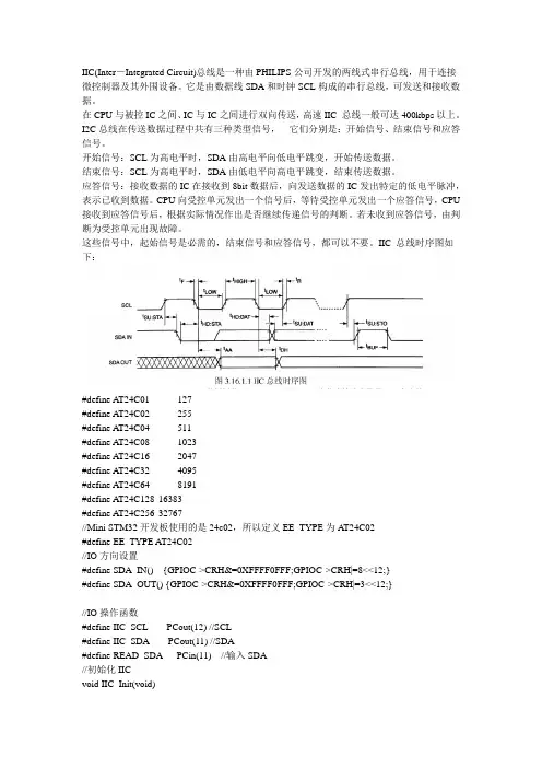
IIC(Inter-Integrated Circuit)总线是一种由PHILIPS公司开发的两线式串行总线,用于连接微控制器及其外围设备。
它是由数据线SDA和时钟SCL构成的串行总线,可发送和接收数据。
在CPU与被控IC之间、IC与IC之间进行双向传送,高速IIC 总线一般可达400kbps以上。
I2C总线在传送数据过程中共有三种类型信号,它们分别是:开始信号、结束信号和应答信号。
开始信号:SCL为高电平时,SDA由高电平向低电平跳变,开始传送数据。
结束信号:SCL为高电平时,SDA由低电平向高电平跳变,结束传送数据。
应答信号:接收数据的IC在接收到8bit数据后,向发送数据的IC发出特定的低电平脉冲,表示已收到数据。
CPU向受控单元发出一个信号后,等待受控单元发出一个应答信号,CPU 接收到应答信号后,根据实际情况作出是否继续传递信号的判断。
若未收到应答信号,由判断为受控单元出现故障。
这些信号中,起始信号是必需的,结束信号和应答信号,都可以不要。
IIC 总线时序图如下:#define AT24C01 127#define AT24C02 255#define A T24C04 511#define AT24C08 1023#define AT24C16 2047#define AT24C32 4095#define AT24C64 8191#define AT24C128 16383#define AT24C256 32767//Mini STM32开发板使用的是24c02,所以定义EE_TYPE为A T24C02#define EE_TYPE AT24C02//IO方向设置#define SDA_IN() {GPIOC->CRH&=0XFFFF0FFF;GPIOC->CRH|=8<<12;}#define SDA_OUT() {GPIOC->CRH&=0XFFFF0FFF;GPIOC->CRH|=3<<12;}//IO操作函数#define IIC_SCL PCout(12) //SCL#define IIC_SDA PCout(11) //SDA#define READ_SDA PCin(11) //输入SDA//初始化IICvoid IIC_Init(void){RCC->APB2ENR|=1<<4;//先使能外设IO PORTC时钟GPIOC->CRH&=0XFFF00FFF;//PC11/12 推挽输出GPIOC->CRH|=0X00033000;GPIOC->ODR|=3<<11; //PC11,12 输出高}//产生IIC起始信号void IIC_Start(void){SDA_OUT(); //sda线输出IIC_SDA=1;IIC_SCL=1;delay_us(4);IIC_SDA=0;//START:when CLK is high,DATA change form high to low delay_us(4);IIC_SCL=0;//钳住I2C总线,准备发送或接收数据}//产生IIC停止信号void IIC_Stop(void){SDA_OUT();//sda线输出IIC_SCL=0;IIC_SDA=0;//STOP:when CLK is high DA TA change form low to high delay_us(4);IIC_SCL=1;IIC_SDA=1;//发送I2C总线结束信号delay_us(4);}//等待应答信号到来//返回值:1,接收应答失败// 0,接收应答成功u8 IIC_Wait_Ack(void){u8 ucErrTime=0;SDA_IN(); //SDA设置为输入IIC_SDA=1;delay_us(1);IIC_SCL=1;delay_us(1);while(READ_SDA){ucErrTime++;if(ucErrTime>250){IIC_Stop();return 1;}}IIC_SCL=0;//时钟输出0return 0;}//产生ACK应答void IIC_Ack(void){IIC_SCL=0;SDA_OUT();IIC_SDA=0;delay_us(2);IIC_SCL=1;delay_us(2);IIC_SCL=0;}//不产生ACK应答void IIC_NAck(void){IIC_SCL=0;SDA_OUT();IIC_SDA=1;delay_us(2);IIC_SCL=1;delay_us(2);IIC_SCL=0;}//IIC发送一个字节//返回从机有无应答//1,有应答//0,无应答void IIC_Send_Byte(u8 txd){u8 t;SDA_OUT();IIC_SCL=0;//拉低时钟开始数据传输for(t=0;t<8;t++){IIC_SDA=(txd&0x80)>>7;txd<<=1;delay_us(2); //对TEA5767这三个延时都是必须的IIC_SCL=1;delay_us(2);IIC_SCL=0;delay_us(2);}}//读1个字节,ack=1时,发送ACK,ack=0,发送nACK u8 IIC_Read_Byte(unsigned char ack){unsigned char i,receive=0;SDA_IN();//SDA设置为输入for(i=0;i<8;i++ ){IIC_SCL=0;delay_us(2);IIC_SCL=1;receive<<=1;if(READ_SDA)receive++;delay_us(1);}if (!ack)IIC_NAck();//发送nACKelseIIC_Ack(); //发送ACKreturn receive;}。
iic多路复用器的工作原理IIC多路复用器,全称为Inter-Integrated Circuit多路复用器,是一种常用于串行通信的集成电路。
它的工作原理是通过将多个设备连接到同一总线上,实现数据的并行传输,从而提高通信效率。
本文将介绍IIC多路复用器的工作原理及其应用。
我们来了解一下IIC多路复用器的基本结构。
它通常由一个主机和多个从机组成,主机负责控制整个通信过程,而从机则负责接收和发送数据。
主机和从机之间通过SCL(时钟线)和SDA(数据线)进行通信。
SCL信号由主机产生并控制,用于同步数据传输的时钟信号;而SDA信号则用于传输数据。
在进行数据传输之前,主机会发送一个起始信号,表示通信的开始。
起始信号的产生是通过将SCL保持为高电平状态,而将SDA从高电平拉到低电平。
之后,主机会发送一个地址字节,用于选择要与之通信的从机。
地址字节的最高位表示读写操作,0表示写操作,1表示读操作;其余的7位用于指定从机的地址。
从机在接收到地址字节之后,会判断自己是否被选中进行通信。
接下来,主机和从机之间开始进行数据传输。
数据传输的方式是通过在SCL的时钟信号下,主机将数据位逐个发送给从机,从机在接收到每个数据位之后,进行确认。
主机和从机通过SDA信号进行数据传输,主机在发送数据位之前,将数据位写入SDA,并将SCL拉低一段时间,等待从机接收。
从机在接收到数据位之后,会发送一个应答信号,表示数据接收成功。
主机在接收到应答信号之后,会继续发送下一个数据位,直到所有数据位都发送完毕。
在数据传输完成之后,主机会发送一个停止信号,表示通信的结束。
停止信号的产生是通过将SCL保持为高电平状态,而将SDA从低电平拉到高电平。
停止信号的发送会使得从机进入空闲状态,准备接收下一次通信。
IIC多路复用器的工作原理非常简单,但是它在实际应用中有着广泛的用途。
首先,它可以用于扩展系统的输入输出接口。
通过连接多个从机到同一总线上,可以实现多个设备与主机之间的并行通信,从而提高系统的通信效率。
IIC总线协议IIC(Inter-Integrated Circuit)总线协议,也被称为I2C协议,是一种串行通信协议,由NXP公司(前身为飞利浦半导体)于1980年代提出。
它是一种简单、高效、灵活的通信协议,常用于连接微控制器、传感器和其他集成电路之间的通信。
1.单主从结构:IIC总线中只能有一个主设备控制通信,并且可以连接多个从设备。
主设备负责发起通信请求和控制总线的时序,从设备则根据主设备的指令进行数据的接收和发送。
2. 传输速率可变:IIC总线的传输速率可以通过改变时钟频率来调整,常用的速率有100kbps、400kbps和1Mbps等。
3.基于地址的设备选择:主设备通过在通信开始时发送设备地址来选择要进行通信的从设备。
一般情况下,IIC总线上的设备地址由7位组成,可以表示128个不同的设备。
4.硬件上的数据确认:每个字节的传输结束后,接收设备会发送一个回应信号(ACK)表示已成功接收数据,而主设备则会在收到回应信号后继续发送下一个字节。
5. 软件上的开始和停止条件:在IIC总线上,通信的开始和结束由两个特殊的信号来标识,即开始条件(Start)和停止条件(Stop)。
1.主设备发送开始条件信号,即在SCL为高电平时,SDA从高电平转为低电平。
2.主设备发送设备地址和读/写位,选择要进行通信的从设备。
3.从设备接收到地址后,发送回应信号。
4.主设备发送数据到从设备或从设备发送数据到主设备。
5.每个字节传输结束后,接收设备发送回应信号。
6.通信结束后,主设备发送停止条件信号,即在SCL为高电平时,SDA从低电平转为高电平。
IIC总线协议在很多应用中得到了广泛的应用。
它不仅可以连接多个从设备,还可以通过从设备之间的数据传递实现简单的操作。
例如,一个主设备可以向一个传感器设备发送指令,然后从另一个设备接收传感器数据,完成数据采集和处理的任务。
总而言之,IIC总线协议是一种简单、高效、灵活的串行通信协议,适用于连接微控制器、传感器和其他集成电路之间的通信。
PTL中文资料IIC总线接口功能描述PTL(Preview, Transmitter, Line)是一种界面适配器,用于数字仪表和控制设备之间的通信。
它是一种基于IIC(Inter-Integrated Circuit)总线接口的通信协议,具有高速、可靠、灵活的特点,广泛应用于工业自动化、汽车电子等领域。
IIC总线接口是一种由飞思卡尔公司推出的串行通信总线,也称为I2C(Inter-Integrated Circuit)总线,适用于电子设备之间短距离通信。
IIC总线支持多个设备通过两根线(SDA和SCL)进行通信,其中SDA (Serial Data Line)是双向数据传输线,SCL(Serial Clock Line)是时钟线,由主设备控制。
通过这两根线的时钟同步通信,可以实现多个设备之间的数据传输。
PTL作为IIC总线接口的一种应用,具有以下功能描述:1.数据传输:PTL通过IIC总线接口实现数据的传输和通信。
通过发送和接收数据的操作,PTL可以实现设备之间的数据交换和共享。
数据传输可以是单向的,也可以是双向的。
PTL可以发送和接收各种类型的数据,例如数字、字符、状态和控制命令等。
2.硬件控制:PTL通过IIC总线接口实现对硬件设备的控制。
PTL可以向设备发送控制命令,例如开关控制、设备初始化、参数设置等。
同时,PTL也可以接收设备的状态反馈和错误信息,以实现对设备的监控和维护。
3.多设备通信:PTL支持多个设备之间的通信。
通过IIC总线的多主模式,PTL可以与多个设备进行通信。
每个设备在IIC总线上都有一个唯一的地址,PTL可以通过地址选择与特定设备通信。
这种多设备通信的方式可以大大简化系统的设计和布线,提高系统的可扩展性和灵活性。
4.数据同步:PTL通过IIC总线的时钟同步通信,实现设备之间的数据同步。
时钟线的同步机制可以确保数据在传输过程中的正确性和完整性。
同时,PTL还可以通过时钟同步的方式控制设备的工作节奏和时序,以实现多个设备之间的协调工作和时钟同步。
i2c总线监测原理
I2C(Inter-Integrated Circuit)总线是一种由PHILIPS公司开发的两线式串行总线,用于连接微控制器及其外围设备。
其监测原理如下:
1.地址和数据传输:在I2C总线上,每个设备都有一个唯一
的地址。
数据在总线上以字节为单位进行传输,通常包括起始位、设
备地址、数据、应答位和停止位。
在数据传输过程中,主设备产生时
钟信号SCL,控制数据传输的时序。
从设备根据主设备的时钟信号,
将数据在SDA线上按位传输。
2.设备检测:I2C总线上,从设备可以在不发送数据的情况
下,通过监听总线的起始信号和从设备的地址信号,来判断是否有主
设备请求与其通信。
3.错误检测:I2C总线通过软件或硬件方式进行错误检测。
软
件错误检测通常由主设备在发送或接收数据后进行校验,以确定数据
是否正确。
硬件错误检测则依赖于总线上设备的硬件故障保护功能。
4.总线仲裁:当多个主设备同时尝试控制总线时,会发生总
线仲裁。
在这种情况下,根据设定的优先级或轮询方式,决定哪个主
设备获得总线的控制权。
5.电源管理和节能:I2C总线允许设备在不需要通信时进入低
功耗模式,通过控制总线的时钟信号来实现设备的唤醒和休眠。
通过这些监测原理,I2C总线可以有效地管理微控制器和其外围设备的通信,提供稳定可靠的数据传输。
iic中的读写使能【最新版】目录1.IIC(IC)总线的概述2.读写使能(R/W)信号的作用3.R/W信号的控制方式4.R/W信号的实际应用正文一、IIC(IC)总线的概述IC(Inter-Integrated Circuit)总线,又称为 IIC 总线,是一种串行通信总线,它是由 Philips 公司(现在的 NXP 半导体公司)于 1980 年代开发的。
IC 总线主要用于低速度、短距离的双向通信,特别适合于连接微处理器和外围设备,如存储器、传感器、LCD 驱动器等。
二、读写使能(R/W)信号的作用在 IC 总线中,读写使能(R/W)信号是控制数据传输方向的重要信号。
R/W 信号由主机设备(如微处理器)生成,用于指示当前数据传输是读操作还是写操作。
在 IC 总线中,有多种数据传输模式,如单主设备模式、多主设备模式等,R/W 信号在这些模式中都发挥着关键作用。
三、R/W 信号的控制方式R/W信号的控制方式分为两种:1.软件控制:通过软件编程实现 R/W 信号的切换。
主机设备根据需要发送 R/W 信号,以控制数据传输方向。
2.硬件控制:通过硬件电路实现 R/W 信号的切换。
这种方法通常用于多主设备模式,以避免 R/W 信号的冲突。
在这种情况下,每个主设备都拥有一个独立的 R/W 信号线,以确保数据传输方向的清晰。
四、R/W 信号的实际应用R/W信号在IC总线中具有广泛的应用,例如:1.在单主设备模式中,主机设备通过 R/W 信号控制从设备,实现数据的读写操作。
2.在多主设备模式中,各个主设备通过 R/W 信号线独立控制数据传输方向,避免冲突。
3.在多主设备通信中,仲裁器也可以利用 R/W 信号来判断哪个主设备具有更高的优先级。
总之,R/W 信号在 IC 总线中起着关键作用,它控制着数据传输的方向,保证了 IC 总线的正常运行。
MINTRODUCTIONThis application note describes the software implementation of I 2 C interface routines for the PIC16CXXX family of devices. Only the master mode of I 2 C interface is implemented in this application note.This implementation is for a single master communica-tion to multiple slave I 2 C devices.Some PIC16CXXX devices, such as the PIC16C64 and PIC16C74, have on-chip hardware which implements the I 2 C slave interface, while other PIC16CXXX devices, such as the PIC16C71 and PIC16C84, do not have the same on-chip hardware.This application note does not describe the I 2 C Bus specifications and the user is assumed to have an understanding of the I 2 C Bus. For detailed information on the bus, the user is advised to read the I 2 C Bus Specification document from Philips/Signetics (order number 98-8080-575). The I 2 C Bus is a two-wire serial bus with multiple possible masters and multiple possi-ble slaves connected to each other through two wires.The two wires consists of a clock line (SCL) and a data line (SDA) with both lines being bi-directional. Bi-direc-tional communication is facilitated through the use of wire and connection (the lines are either active-low or passive high). The I 2 C Bus protocol also allows collision detection, clock synchronization and hand-shaking for multi-master systems. The clock is always generated by the master, but the slave may hold it low to generate a wait state.In most systems the microcontroller is the master andthe external peripheral devices are slaves. In these cases this application note can be used to attach I 2 C slaves to the PIC16CXXX (the master) microcontroller.The multi-master system is not implemented because it is extremely difficult to meet all the I 2 C Bus timing spec-ifications using software. For a true slave or multi-mas-ter system, some interface hardware is necessary (like ST ART & STOP bit detection).In addition to the low level single master I 2 C routines, a collection of high level routines with various message structures is given. These high level macros/routines can be used as canned routines to interface to most I 2 C slave devices. As an example, the test program talks to two Serial EEPROMs (Microchip’s 24LC04and 24LC01).IMPLEMENTATIONTwo levels of software routines are provided. The low-level routines “ i2c_low.asm” are provided in Appendix A and the high level routines “ i2c_high.asm ” are provided in Appendix B. The messages passed (communicated on the two wire network) are abbreviated and certain notation is used to represent Start, Stop and other conditions. These abbreviations are described in T able 1.TABLE 1:DESCRIPTION OF ABBREVIATIONS USEDAbbreviationsExplanationS Start Condition P Stop ConditionSlvAR Slave Address (for read operation)SlvAW Slave Address (for write operation)A Acknowledge condition (positive ACK)N Negative Acknowledge condition (NACK)DData byte, D[0] represents byte 0, D[1] represents second byteAN554Software Implementation of I 2 C ™ Bus MasterAN554Message FormatIn the high level routines, the basic structure of the mes-sage is given. Every I2C slave supports one or more message structures. For example, Microchip’s 24LC04 Serial EEPROM supports the following message (to write a byte to Serial EEPROM at current address counter) S-SlvAW-A-D-A-P which basically means the following sequence of operations are required:a)Send Start Bitb)Send Slave Address for Write Operationsc)Expect Acknowledged)Send Data Bytee)Expect Acknowledgef)Issue a STOP ConditionSlave AddressBoth 10-bit and 7-Bit addressing schemes are implemented as specified by the I2C Bus specification. Before calling a certain sub-routine (high level or low-level), the address of the slave being addressed must be loaded using either “LOAD_ADDR_8” (for 7-bit address slaves) or “LOAD_ADDR_10” macro (for 10-bit address slaves). These macros not only load the address of the slaves for all the following operations, but also setup conditions for 7- or 10-bit addressing modes. See the macros section for more details.CLOCK STRETCHINGIn the I2C Bus, the clock (SCL line) is always provided by the master. However, the slave can hold the line low even though the master has released it. The master must check this condition and wait for the slave to release the clock line. This provides a built-in wait state for the I2C Bus. This feature is implemented and can be turned on or off as an assembly time option (by configuring the _ENABLE_BUS_FREE_TIME flag to be TRUE or FALSE). If the clock is held low for too long, say 1 ms, then an error condition is assumed and a T0CKI interrupt is generated.ARBITRATIONThe I2C Bus specifies both bit-by-bit and byte mode arbitration procedures for multi-master systems. However, the arbitration is not needed in a single master system, and therefore is not implemented in this application note.HARDWARETwo I/O pins are used to emulate the Clock Line, SCL, and the Data Line, SDA. In the example test program, RB0 is used as the SCL line and RB1 as the SDA line. On initialization, these I/O lines are configured as input pins (tri-state) and their respective latches are loaded with '0's. T o emulate the high state (passive), these lines are configured as inputs. T o emulate the active low state, the pins are configured as outputs (with the assumption of having external pull-up resistors on both lines).For devices that have the on-chip I2C hardware (SSP module), slope control of the I/O is implemented on the SCK and SDA pins. For software not implemented on the SCK and SDA pins of the SSP module, external components for slope control of the I/O may be required by the system.AN554I2C ROUTINESStatus Register (File Register “Bus_Status”)The bit definitions of the status register are described inthe table given below. These bits reflect the status of theI2C Bus.Bit #Name Description0_Bus_Busy 1 = Start Bit transmitted0 = STOP condition1_Abort It is set when a fatal error condition is detected. The user must clear this bit.This bit is set when the clock line, SCL, is stuck low.2_Txmt_Progress 1 = transmission in progress3_Rcv_Progress 1 = reception in progress4_Txmt_Success 1 = transmission successfully completed0 = error condition5_Rcv_Success 1 = reception successfully completed0 = error condition6_Fatal_Error 1 = FA TAL error occurred (the communication was aborted).7_ACK_Error 1 = slave sent ACK while the master was expecting an ACK.This may happen for example if the slave was not responding to a message. Control Register (File Register “Bus_Control”)The bit definitions of the control register are describedin the table given below. These bits must be set by thesoftware prior to performing certain operations. Someof the high level routines described later in this sectionset these bits automatically.Bit #Name Description0_10BitAddr 1 = 10-bit slave addressing0 = 7-bit addressing.1_Slave_RW 1 = READ operation0 = WRITE operation.2_Last_Byte_Rcv 1 = last byte must be received. Used to send ACK.3, 4, 5—Unused bits, can be used as general purpose bits.6_SlaveActive A status bit indicating if a slave is responding. This bit is set or cleared bycalling the I2C_TEST_DEVICE macro. See description of thisI2C_TEST_DEVICE macro.7_TIME_OUT_ A status bit indicating if a clock is stretched low for more than 1 ms, indicatinga bus error. On this time out, the operation is aborted.AN554Lower Level RoutinesFunction Name DescriptionInitI2CBus_Master Initializes Control/Status Registers, and set SDA & SCL lines.Must be called on initialization.TxmtStartBit Transmits a ST ART (S) condition.TxmtStopBit T ransmits a STOP (P) condition.LOAD_ADDR_8The 7-bit slave’s address must be passed as a constant parameter.LOAD_ADDR_10The 10-bit slave’s address must be passed as a constant parameter.Txmt_Slave_Addr Transmits a slave address. Prior to calling this routine, the address of theslave being addressed must be loaded using LOAD_ADDR_8 orLOAD_ADDR_10 routines. Also the Read/Write condition must be set in thecontrol register.SendData Transmits a byte of data. Prior to calling this routine, the byte to betransmitted must be loaded into DataByte file register.GetData Receives a byte of data in DataByte file register. If the data byte to bereceived is the last byte, the _Last_Byte_Rcv bit in control register must beset prior to calling this routine.AN554MACROSHigh LevelThe high level routines are implemented as a mixture of function calls and macros. These high level routines call the low level routines described previously. In most cases only a few of the high level routines may be needed and the user can remove or not include the routines that are not necessary to conserve program memory space. Examples are given for a few functions.I2C_TEST_DEVICEParameters:NonePurpose:T o test if a slave is present on the network.Description:Before using this macro, the address of the slave being tested must be loaded usingLOAD_ADDR_8 or LOAD_ADDR_10 macro. If the slave under test is present, then“_SlaveActive" status bit (in Bus_Control file register) is set. If not, then this bit iscleared, indicating that the slave is either not present on the network or is not listening.Message:S-SlvAW-A-PExample:LOAD_ADDR_8 0xA0 ; 24LC04 addressI2C_TEST_DEVICEbtfss _SlaveActive ; See If slave is respondinggoto SlaveNotPresent ; 24LC04 is not present; Slave is present; Continue with programI2C_WRParameters: _BYTES_, _SourcePointer__BYTES_ Number of bytes starting from RAM pointer _SourcePointer__SourcePointer_ Data Start Buffer pointer in RAM (file registers) Purpose: A basic macro for writing a block of data to a slaveDescription:This macro writes a block of data (# of bytes = _BYTES_) to a slave.The starting address of the block of data is _SourcePointer_. If an error occurs, the mes-sage is aborted and the user must check Status flags (e.g. _Txmt_Success bit) Message:S-SlvAW-A-D[0]-A.....A-D[N-1]-A-PExample:btfsc _Bus_Busy ; Check if bus is freegoto $-1LOAD_ADDR_8 _Slave_1_AddrI2C_WR 0x09, DataBegin ;AN554I2C_WR_SUBParameters: _BYTES_, _SourcePointer_, _Sub_Address__BYTES_ Number of bytes starting from RAM pointer _SourcePointer__SourcePointer_ Data Start Buffer pointer in RAM (file Registers)_Sub_Address_ Sub-address of the SlavePurpose:Write a block of data to a slave starting at slave’s sub-addrDescription:Same as I2C_WR function, except that the starting address of the slave is also specified.For example, while writing to an I2C Memory Device, the sub-addr specifies the startingaddress of the memory. The I2C may prove to be more efficient than this macro in mostsituations. Advantages will be found for Random Address Block Writes for Slaves withAuto Increment Sub-addresses (like Microchip’s 24CXX series Serial EEPROMs).Message:S-SlvAW-A-SubA-A-D[0]-A.....A-D[N-1]-A-PExample:LOAD_ADDR_8 _Slave_2_Addr ; Load addr of 7-bit slaveI2C_WR_SUB 0x08, DataBegin+1, 0x30In the above example, 8 Bytes of data starting from addr (DataBegin+1) is written to 24LC04Serial EEPROM beginning at 0x30 addressI2C_WR_SUB_SWINCParameters: _BYTES_, _SourcePointer_, _Sub_Address__BYTES_ Number of bytes starting from RAM pointer _SourcePointer__SourcePointer_ Data Start Buffer pointer in RAM (file Registers)_Sub_Address_ Sub-address of the SlavePurpose:Write a block of data to a slave starting at slave’s sub-addrDescription:Same as I2C_WR_SUB function, except that the sub-address (incremented) is sentafter every data byte. A very inefficient message structure and the bus is given up aftereach data byte. This is useful for when the slave does not have an auto-incrementsub-address feature.Message:S-SlvAW-A-(SubA+0)-A-D[0]-A-PS-SlvAW-A-(SubA+1)-A-D[1]-A-Pand so on until #of BytesAN554I2C_WR_BYTE_MEMParameters: _BYTES_, _SourcePointer_, _Sub_Address__BYTES_ Number of bytes starting from RAM pointer _SourcePointer__SourcePointer_ Data Start Buffer pointer in RAM (file Registers)_Sub_Address_Sub-address of the SlavePurpose:Write a block of data to a slave starting at slave’s sub-addressDescription:Same as I2C_WR_SUB_SWINC, except that a delay is added between each message.This is necessary for some devices, like EEPROMs, which accept only a byte at a timefor programming (devices without on-chip RAM buffer) and after each byte a delay isnecessary before a next byte is written.Message:S-SlvAW-A-(SubA+0)-A-D[0]-A-PDelay 1 msS-SlvAW-A-(SubA+1)-A-D[1]-A-PDelay 1 ms •••and so on until #of BytesI2C_WR_BUF_MEMParameters: _BYTES_, _SourcePointer_, _Sub_Address_, _Device_BUF_SIZE__BYTES_ Number of bytes starting from RAM pointer _SourcePointer__SourcePointer_ Data Start Buffer pointer in RAM (file Registers)_Sub_Address_ Sub-address of the Slave_Device_BUF_SIZE_ the slaves on-chip buffer sizePurpose:Write a block of data to a slave starting at slave’s sub-addrDescription:This Macro/Function writes #of _BYTES_ to an I2C memory device. However somedevices, especially EEPROMs, must wait while the device enters into programmingmode. But some devices have an on-chip temperature data hold buffer and is used tostore data before the device actually enters into programming mode. For example, the24C04 series of Serial EEPROMs from Microchip have an 8-byte data buffer. So onecan send 8 bytes of data at a time and then the device enters programming mode. Themaster can either wait until a fixed time and then retry to program or can continuouslypoll for ACK bit and then transmit the next block of data for programming.Message:I2C_SUB_WR operations are performed in loop and each time data buffer of BUF_SIZEis output to the device. Then the device is checked for busy and when not busy anotherblock of data is written.AN554I2C_READParameters: _BYTES_, _DestPointer__BYTES_ Number of bytes starting from RAM pointer _SourcePointer__DestPointer_ Data Start Buffer pointer in RAM (file Registers) Purpose: A basic macro for reading a block of data from a slaveDescription:This macro reads a block of data (number of bytes = _BYTES_) from a slave. The start-ing address of the block of data is _DestPointer_. If an error occurs, the message isaborted and the user must check Status flags (e.g. _Rcv_Success bit). Note that on thelast byte to receive, NACK is sent.Message:S-SlvAR-A-D[0]-A-.....-A-D[N-1]-N-PExample:LOAD_ADDR_10 _Slave_3_AddrI2C_READ_SUB 8, DataBeginbtfss _Rcv_Successgoto ReceiveErrorgoto ReceiveSuccessIn the example above, 8 bytes of data is read from a 10-bit slave and stored in the master’s RAMstarting at address DataBegin.AN554I2C_READ_SUBParameters: _BYTES_, _DestPointer_, _SubAddress_BYTES_ Number of bytes starting from RAM pointer _SourcePointer__DestPointer_ Data Start Buffer pointer in RAM (file Registers)_SubAddress_ Sub-address of the slavePurpose: A basic macro for reading a block of data from a slaveDescription:This macro reads a block of data (# of bytes = _BYTES_) from a slave starting at slave’ssub-address _SubAddress. The data received is stored in master’s RAM starting ataddress _DestAddress. If an error occurs, the message is aborted and the user mustcheck Status flags (e.g. _Rcv_Success bit).This MACRO/Subroutine reads a message from a slave device preceded by a write ofthe sub-address between the sub-address write and the following reads, a STOP con-dition is not issued and a “REPEATED ST ART” condition is used so that another masterwill not take over the bus, and also that no other master will overwrite the sub-addressof the same slave. This function is very commonly used in accessing Random/Sequen-tial reads from a memory device (e.g., 24CXX serial of Serial EEPROMs fromMicrochip).Message:S-SlvAW-A-SubAddr-A-S-SlvAR-A-D[0]-A-.....-A-D[N-1]-N-PExample:LOAD_ADDR_10 _Slave_3_AddrI2C_READ 8, DataBegin, 0x60btfss _Rcv_Successgoto ReceiveErrorgoto ReceiveSuccessIn the example above, 8 bytes of data is read from a 10-bit slave (starting at address 0x60h) andstored in the master’s RAM starting at address DataBegin.I2C_READ_BYTE or I2C_READ_STATUSParameters: _DestPointer__DestPointer_ Data Start Buffer pointer in RAM (file Registers) Purpose:To read a Status Byte from SlaveDescription:Several I2C Devices can send a Status Byte upon reception of the control byte.This Macro reads a Status byte from a slave to the master’s RAM location_DestPointer_. This function is basically the same as I2C_READ for a single byte read.As an example of this command, the 24Cxx serial Serial EEPROM from Microchip willsend the memory data at the current location when I2C_READ_STATUS function iscalled. On successful operation of this command, W register = '1' else W register = '0'on errors.Message:S-SlvAR-A-D-A-N-PAN554I2C_WR_SUB_WRParameters: _Bytes1_, _SrcPtr1_, _SubAddr_, _Bytes2_, _SrcPtr2__Bytes1_ Number of bytes in the first data block_SrcPtr1_ Starting address of first data block_SubAddr_ Sub-address of the slave_Bytes2_ Number of bytes in the second data block_SrcPtr2_ Starting address of second data blockPurpose:T o send two blocks of data to a slave at its sub addressDescription:This Macro writes two blocks of data (of variable length) starting at slave’s sub-address_SubAddr_. This Macro is essentially the same as calling I2C_WR_SUB twice, but aSTOP bit is not sent in-between the transmission of the two blocks. This way the Bus isnot given up.This function may be useful for devices which need two blocks of data in which the firstblock may be an extended address of a slave device. For example, a large I2C memorydevice, or a teletext device with an extended addressing scheme, may need multiplebytes of data in the first block that represents the actual physical address and is followedby a second block that actually represents the data.Message: S-SlvW-A-SubA-A-D1[0]-A-....-D1[N-1]-A-D2[0]-A-.....A-D2[M-1]-A-PI2C_WR_SUB_RDParameters: _Count1_, _SrcPtr_, _SubAddr_, _Count2_, _DestPtr__Count1_ Length of the source buffer_SrcPtr_ Source pointer address_SubAddr_ Sub-address of the slave_Count2_ Length of the destination buffer_DestPtr_ Address of destination bufferPurpose:To send a block of data and then receive a block of dataDescription:This macro writes a block of data (of length _Count1_) to a slave starting at sub-address_SubAddr_ and then reads a block of data (of length _Count2_) to the master’s destina-tion buffer (starting at address _DestPtr_). Although this operation can be performedusing previously defined Macros, this function does not give up the bus in between theblock writes and block reads. This is achieved by using the Repeated Start Condition.Message :S-SlvW-A-SubA-A-D1[0]-A-.....-A-D1[N-1]-A-S-SlvR-A-D2[0]-A-......A-D2[M-1]-N-PAN554I2C_WR_COM_WRParameters: _Count1_, _SrcPtr1_, _Count2_, _SrcPtr2__Count1_ Length of the first data block_SrcPtr1_ Source pointer of the first data block_Count2_ Length of the second data block_SrcPtr2_ Source pointer of the second data blockPurpose:To send two blocks of data to a slave in one message.Description:This macro writes a block of data (of length _Count1_) to a slave and then sendsanother block of data (of length _Count2_) without giving up the bus.For example, this kind of transaction can be used in an I2C LCD driver where a block ofcontrol and address information is needed and then another block of actual data to bedisplayed is needed.Message : S-SlvW-A-D1[0]-A-.....A-D1[N-1]-A-D2[0]-A-......-A-D2[M-1]-A-PAPPLICATIONSThe I2C Bus is a simple two wire serial protocol forinter-IC communications. Many peripheral devices (act-ing as slaves) are available in the market with I2C inter-face (e.g., serial EEPROM, clock/calendar, I/O Portexpanders, LCD drivers, A/D converters). Althoughsome of the PIC16CXXX devices do not have on-chipI2C hardware interface, due to the high speed through-put of the microcontroller (250 ns @ 16 MHz inputclock), the I2C bus can be implemented using software.© 1997 Microchip Technology Inc.DS00554C-page 11。