格力水冷柜机技术服务手册
- 格式:pdf
- 大小:1.63 MB
- 文档页数:76
USES HFC-134A REFRIGERANTOWNERS MANUALBacksplash Model Water CoolersFIG. 142413328,432926253624352723222631322434213839See Fig. 3 (on Page 3)For Push Bar Mechanism29374030NOTE: Non-refrigerated units do notinclude all electrical and refrigeration com-ponents shown above. Other components and rough-in are the same as shown.Uses HFC-134A refrigerantNote: Danger! Electrical shock hazard. Disconnect power before servicing unit.F IG . 2L E G E N D /L E Y E N D A /L ÉG E N D E A = R E C O M M E N D E D W A T E R S U P P L Y L O C A T I O N 3/8 O .D . U N P L A T E D C O P P E R T U B E C O N N E C T S T U B 1-1/2 I N . (38m m ) O U T F R O M W A L L S H U T O F F B Y O T H E R S B = R E C O M M E N D E D L O C A T I O N F O R W A S T E O U T L E T 1-1/4” O .D . D R A I N C = 1-1/4 T R A P N O T F U R N I S H E D **D = E L E C T R I C A L O U T L E T L O C A T I O N E = I N S U R E P R O P E R V E N T I L A T I O N B Y M A I N T A I N I N G 6" (152m m ) (M I N .) C L E A R A N C E F R O M C A B I N E T L O U V E R S T O W A L L .F = P O W E R C O R D 1-1/2F E E T (457m m ) L O N G G = A L T . E L E C T R I C A L O U T L E T L O C A T I O N H = T H I S B O L T H O L E M U S T B E U S E D F O R F A S T E N I N G U N I T T O W A L L .J = O R I F I C E H E I G H T 1-1/4" (32m m ) A B O V E R I MF I N I S H E D F L O O RHANGER BRACKETS & TRAP INSTALLATION1) Remove hanger bracket fastened to back of cooler byremoving one (1) screw.2) Mount the hanger bracket and trap as shown in Figure 2. NOTE: Hanger Bracket MUST be supported securely. Add fix -ture support carrier if wall will not provide adequate support.IMPORTANT:• 5-1/2 in. (140mm) dimension from centerline of unit to centerline of trap must be maintained for proper fit. Anchor hanger securely to wall using all mounting holes.3) Install straight valve for 3/8" O.D. unplated copper tube.INSTALLATION OF COOLER4) Hang the cooler on the hanger bracket. Be certain the hanger bracket is engaged properly in the slots on the cooler back as shown in Figure 2.5) Loosen the two (2) screws holding the lower front panel at the bottom of cooler base and two (2) screws at the top. Remove the front panel and set aside.6) Connect water inlet line--See Note 4 of General Instructions.7) Remove the slip nut and gasket from the trap and install them on the cooler waste line making sure that the end of the waste line fits into the trap. Assemble the slip nut and gasket to the trap and tighten securely.START UPAlso See General Instructions8) Stream height is factory set at 35 PSI. If supply pressure varies greatly from this, adjust screw, ac-cessible by removing front panel (Item 7, Fig. 3). CW adjustment will raise stream and CCW adjustment will lower stream. For best adjustment, stream should hit basin approximately 6-1/2” (165mm) from bubbler.9) Replace the front panel and secure by retightening four (4) screws.PUSH BAR MECHANISMLEGENDA) Note: Water flow directionB) Adjust this screw to eliminate mechanism “Free Play” or continuous flow from bubbler conditions. (See ADJUSTMENT PROCEDURE)C) Stream height adjustment (see note #8)Water Valve Mechanism - ADJUSTMENT PROCEDURE:- Turn adjustment screw (Item 9) “Counter-Clockwise” until water flow from bubbler starts.- Turn adjustment screw “Clockwise” until water flow stops, THEN turn an additional 1/2 turn.NOTE: Adjustments stated above are viewed from underneath unit (bottom side of dispenser panel Item 1)NOTE: If continuous flow occurs at the end of the compressor cycle, turn cold control (Item 46) counterclockwise 1/4 turn.ITEM NO.PART NO.Panel - Bottom DispenserKit - Push Bar/Pivot Blocks/Bumpers/Rivets Kit - Pushbars (Front & Sides)/Inserts/Nuts Kit - Front/Side Pushbar Bracket/Screws Panel - Right Side Panel - Left Side Panel - Front PushScrew - Regulator Brkt. Mtg.Screw - Shoulder x 1/2" Lg.Kit - Regulator/Holder/Nut Bracket - Regulator Mounting Hex Nut26588C 98537C 98895C 98789C See Color Table See Color Table See Color Table75502C 70935C 98531C 23003C 40045CItem No. 5Part No.(w/o hole)COLOR TABLEPlatinum Vinyl Stainless Steel Almond Vinyl Slate Vinyl26644C 26637C 26636C 26646C 26659C 26652C 26651C 26661C 26614C 26607C 26606C 26616C PANEL COLOR123456789101112DESCRIPTION26629C 26622C 26621C 26631C 26599C 26600C 26601C 26602CItem No. 5Part No.(with hole)Item No. 6Part No.(w/o hole)Item No. 6Part No.(with hole)Item No. 7Part No.FIG. 36434733334289 B2C44212111010101345A115V PARTS LISTITEM NO.PART NO.21222324252627282930313233343536*37383940414243Power Cord Fan BracketKit - Fan Motor Assy/Blade/Shroud/Nut/Screws Angle - Bracket Corner Bracket - Front Support Bracket - Basin Mounting Frame - Back/BottomClip (Front and Rear Panels)Kit - Bubbler Chrome (Bubbler/Nipple/Gaskets)Tubing - Poly (Cut to Length)Kit - Condenser/Drier DrierWrapper - Platinum Vinyl Wrapper - Slate Vinyl Wrapper - Almond Vinyl Wrapper - Stainless SteelKit - Compr Mtg (Grommets/Cotter Pin/Washers)StrainerKit - Evaporator Replacement Assembly Compressor Serv. PakKit - Electrical (Relay/Cvr/Overload)Kit - Cold Control/Screws Kit - Heat Exchanger/DrierKit - Drain (Tailpipe/Strainer/Ferrule/Gasket)Basin - Stainless Steel Screw - Basin Mtg.36208C 27095C 98775C 27093C 27094C 28797C 27097C 70142C 98533C 56092C 98776C 66703C 26680C 26682C 22707C 22708C 000000025255996C 98724C 36322C 000000023898773C 98778C 98790C 26664C 75536CDESCRIPTION*INCLUDES RELAY & OVERLOAD. IF UNDER WARRANTY , REPLACE WITH SAME COMPRESSOR USED IN ORIGINAL ASSEMBLY .NOTE: All correspondence pertaining to any of the above water coolers or orders for repair parts MUST include Model No. and Serial No. of cooler, name and part number of replacement part.PRINTED IN U.S.A.2222 CAMDEN COURT OAK BROOK, IL 60523630.574.3500CORRECT STREAM HEIGHTFIG. 4FOR PARTS, CONTACT YOUR LOCAL DISTRIBUTOR OR VISIT OUR WEBSITE 35827C 0000000244100000214798751C 35826CPower CordKit - Fan Motor Assy/Blade/Shroud/Nut/Screws Compressor Serv. PakKit - Electrical (Relay/Cvr/Overload)Power - Inlet2125*3738-230V-50Hz PARTS LIST。
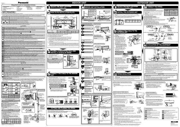
PRINTED IN MALAYSIAF615171ENGLISHF615171•If a drain elbow is used, the unit should be placed on a stand which is taller than 3 cm.•If the unit is used in an area where temperaturefalls below 0°C for 2 or 3 days in succession, it is recommended not to use a drain elbow, for the drain water freezes and the fan will not rotate.)) ))If the unit is installed at 10 m distance, the quantity of additional refrigerant should be 50 g .... (10-7.5) m x 20 g/m = 50 g.•IMPORTANT (only for E9NKKW)This product has been designed and manufactured to meet ENERGY STAR ® criteria for energy effi ciency when matched with appropriate coil components. However, proper refrigerant charge and proper air fl ow are critical to achive rated capacity and effi ciency. Installation of this product should follow the manufacturer’s refrigerant charging and air fl ow instructions. Failure to con fi rm proper charge and air fl ow may reduce energy ef fi ciency and shorten equipment life.Required tools for Installation Works1 Philips screw driver2 Level gauge3 Electric drill, hole core drill (ø70 mm)4 Hexagonal wrench (4 mm)5 Spanner6 Pipe cutter7 Reamer 8 Knife9 Gas leak detector 10 Measuring tape 11 Thermometer 12 Megameter13 Multimeter 14 T orque wrench 18 N•m (1.8 kgf.m)42 N•m (4.3 kgf.m)55 N•m (5.6 kgf.m)65 N•m (6.6 kgf.m)100 N•m (10.2 kgf.m)15 Vacuum pump 16 Gauge manifold•Read the following “SAFETY PRECAUTIONS” carefully before installation.•Electrical work must be installed by a licensed electrician. Be sure to use the correct rating of the power plug and main circuit for the model to be installed. •The caution items stated here must be followed because these important contents are related to safety. The meaning of each indication used is as below.SAFETY PRECAUTIONS•Open front panel and remove air fi lters.(Drainage checking can be carried out without removing the front grille.)•Pour a glass of water into the drain tray-styrofoam.•Ensure that water fl ows out from drain hose of the indoor unit.•Operate the unit at cooling/heating operation mode for fi fteen minutes or more.•Measure the temperature of the intake and discharge air. •Ensure the difference between the intake temperature andthe discharge is more than 8°C during Cooling operation or more than 14°C during Heating operation.1. Open the front panel.2. Remove the air fi lters.3. Put the Anti-bacterial fi lter into place as shown in illustration at right.INST ALLATION OF ANTI-BACTERIAL FILTEREVALUA TION OF THE PERFORMANCEDISPOSAL OF OUTDOOR UNIT DRAIN WATERCHECK THE DRAINAGECHECK ITEMSPlease follow the steps below to take out front grille if necessary such as when servicing.1. Set the vertical airfl ow direction louvers to the horizontal position.2. Slide down the 2 caps on the front grille as shown in the illustration at right, and then remove the 2 mounting screws.3. Pull the lower section of the front grille towards you to remove the front grille.When reinstalling the front grille, fi rst set the vertical airfl ow direction louver to the horizontal position and then carry out above steps 2 - 3 in the reverse order.HOW TO T AKE OUT FRONT GRILLEAUTO SWITCH OPERA TIONThe below operations will be performed by pressing the “AUTO” switch.1. AUTO OPERATION MODEThe Auto operation will be activated immediately once the Auto Switch is pressed and release before 5 sec..2. TEST RUN OPERA TION (FOR PUMP DOWN/SERVICING PURPOSE)The T est Run operation will be activated if the Auto Switch is pressed continuously for more than 5 sec. to below 8 sec..A “pep” sound will occur at the fi fth sec., in order to identify the starting of T est Run operation.3. HEA T NG TR AL OPERAT ONPress the “AUTO” switch continuously for more than 8 sec. to below 11 sec. and release when a “pep pep” sound is occured at eight sec. (However, a “pep” sound is heard at fi fth sec..) then press Remote controller “A/C Reset” button once. Remote controller signal will activate operation force heating mode.4. REMOTE CONTROLLER RECEIVING SOUND ON/OFFThe ON/OFF of Remote controller receiving sound can be changed by the following steps:a) Press “AUTO” switch continuously for more than 16 sec. to below 21 sec.. A “pep”, “pep”, “pep”, “pep” sound will occur at the sixteenth sec.. b) P ress the “A/C Reset” button once. Remote controller signal will activate the Remote controller sound setting mode.c) P ress the “AUTO” switch once to select Remote controller receiving sound ON/OFF . A “pep” sound indicates receiving sound ON, and a “pep” sound indicates receiving sound OFF .Is there any gas leakage at fl are nut connections?Has the heat insulation been carried out at fl are nut connection?Is the connection cable being fi xed to terminal board fi rmly?Is the connection cable being clamped fi rmly?Is the drainage ok?(Refer to “Check the drainage” section)Is the earth wire connection properly done?Is the indoor unit properly hooked to the installation plate?Is the power supply voltage complied with rated value?Is there any abnormal sound?Is the cooling/heating operation normal?Is the thermostat operation normal?Is the remote control’s LCD operation normal?Is the Anti-bacterial fi lter installed?。
安装使用说明书螺杆式水冷冷水机组珠 海 格 力 电 器 股 份 有 限 公 司为了正确使用本产品,请在使用前仔细阅读本使用说明书,并妥善保存以供今后参考。
适用机型:LSBLG190H、LSBLG260H LSBLG290H、LSBLG325H LSBLG370H、LSBLG430H LSBLG480H、LSBLG550H LSBLG650H、LSBLG780H LSBLG850H、LSBLG960H LSBLG1160H、LSBLG1260H LSBLG1360H、LSBLG1560H LSBLG1700H、LSBLG1900HLSBLG180H/Nb、LSBLG210H/Nb LSBLG240H/Nb、LSBLG300H/Nb LSBLG340H/Nb、LSBLG380H/Nb LSBLG450H/Nb、LSBLG500H/Nb LSBLG580H/Nb、LSBLG640H/Nb LSBLG680H/Nb、LSBLG760H/Nb LSBLG880H/Nb、LSBLG1000H/Nb LSBLG1160H/Nb、LSBLG1280H/Nb LSBLG1400H/Nb、LSBLG1500H/Nb为了让用户能正确使用螺杆式水冷冷水机组,达到预期的运行效果,请仔细阅读本使用说明书。
读本说明书前特作以下说明:(1).本使用说明书适用于格力螺杆式水冷冷水机组,包括机组安装、使用、操作和维护。
有关微机控制使用说明详见格力《螺杆机按键显示器通用操作说明书》或《螺杆机触摸屏通用操作说明书》。
(2).机组安装使用前务必熟读本说明书,若有问题或不明之处,请与我公司商用空调经营部联系。
(3).为了保证您能安全使用本系列机组,请遵照《安全警示》的要求,务必按照这些要求执行。
(4).运行中务必做好运行记录,以备随时了解机组的使用状况及事后故障原因分析。
(5).请将本说明书务必保存在直接担任运行操作者和维护者手中。
(6).万一发生故障不能运行,请按下述要领尽快与我公司商用空调经营部联系。
注意:请在安装使用前仔细阅读本说明书! 单元式空调机水冷柜式空调机组使用安装说明书珠海格力电器股份有限公司GREE ELECTRIC APPLIANCES, INC. OF ZHUHAI前言格力水冷柜式空调机组严格遵循国标GB/T17758-1999《单元式空气调节机》(UNITARY AIR CONDITIONERS)设计,确保该机组具有良好的运行状态、高度的可靠性,以及优良的适应性。
本手册包括有关机组正确安装、调试、开启及维修的说明。
请于开启或检修机组前,仔细阅读本手册!z安装工作必须由经过训练的专业人员进行z格力公司对于任何由于安装、调试不当,不必要的维修以及不遵循本手册中的规定而造成的人员伤害和机器损伤不承担任何责任保修范围必须符合下列条件:z机组的首次开启必须有格力电器股份有限公司特约维修安装点的专业维修人员来进行z只能使用格力电器股份有限公司提供的各种备用零部件z本手册中规定的所有机组运行及维修注意事项,必须严格的按照规定的时间来进行违反上述任何条件,包修将自动失效。
本说明书中所有插图及信息仅供参考,生产厂家有权在任何时候就销售或生产方面的原因而进行必要的改动,而不另行通知!目录一、机组特点 (3)二、机组技术参数 (4)1、型号规格与性能参数 (4)2、机组工作原理 (6)3、机组外形尺寸 (7)三、机组的安装 (11)1、检查 (11)2、机组的运输搬运 (11)3、机组安装空间位置与间隙 (12)4、噪声的控制 (12)5、风机的安装调节 (12)6、电气安装 (13)7、冷却水系统安装 (14)8、风管安装 (16)四、机组调试与开机 (17)1、安装后,启动前的检查 (17)2. 机组运行调试 (17)3.控制器显示 (18)4、控制器的操作 (18)5、机组运行范围 (19)五、维护保养与故障诊断 (19)1、机组的日常操作与维护 (19)2、机组维修与保养 (20)3、循环冷却水系统维护与保养 (20)4、故障分析与排除方法 (21)六、售后服务 (23)一、机组特点格力L系列水冷柜式空调机组设计成能直接送风或通过风道送风来达到调节室内环境的目的,其特点如下:1. 适用范围广,安装方便格力水冷柜式空调机组可满足工商业的各项需要,广泛用于轻工、医疗、商场、旅游等行业,机组采用整体式设计, 结构紧凑、占地省,以冷却水吸热来进行制冷剂的冷凝液化,效率高。
智能多联技术服务手册目录第一章产品篇1.产品种类2.产品命名规则3.产品特点4.产品技术参数表5.产品性能修正6.产品工作原理与控制7.机组安装尺寸及空间要求第二章控制篇1.线控器介绍2.遥控器介绍3.远程监控系统第三章维修篇1.机组故障一览表2.典型故障排查3.案例分析4.机组配电5.关键部件及拆装6.爆炸图及零部件清单第一章产品篇1.产品种类1.1智能多联室外机1.3 智能多联室内外机搭配表室内机容量 室内机组型式 序室外机型号室内机数量(台)(数字×100W)风管式 天井式 落地式 挂壁式 165 ● ● ● 1 50 ● ● ● ● 1GMV(L)-J150W3/D1 35 ● ● 165 ● ● ● 2 35 ● ● 2GMV(L)-J150W4/D125 ● ● 3GMV(L)-J130W2/D2 65 ● ● ● 165 ● ● ● 1 35 ● ● 4GMV(L)-J130W3/D125 ● ● 5GMV(L)-J130W4/D150●●●●(续上)室内机容量 室内机组型式 序 室外机型号室内机数量(台)(数字×100W)风管式 天井式落地式挂壁式1 35 ● ● 5 GMV(L)-J130W4/D2 25 ● ● 6 GMV(L)-J100W2/D 2 50 ● ● ● ● 1 50 ● ● ● ● 7 GMV(L)-J100W3/D 2 25 ● ● 8 GMV(L)-J100W4/D 4 25 ● ● 1 50 ● ● ● ● 9GMV(L)-J85W2/D1 35 ● ● 1 35 ● ● 10 GMV(L)-J85W3/D2 25 ● ● 11GMV(L)-J260W2/C2130●●●2.产品命名规则2.1室外机命名规则 2.1.1 室外机型号构成GMV/W 补充代号型式代号设计序号室外机代号功能特征气候类型制冷量*电源种类补充制冷剂种类产品代号2.1.2 室外机型号含义标准主型号含义产品 代号气候类型型式代号功能特征制冷量室外机 代号* 补充代号:压缩机(或室外机)数量表示方法GMVT1-省略 T2-低温 气候 T3-高温 气候热泵型 省略 L-单冷型J-智能多联名义制冷量×102 (W )W用数字表示, 单压缩机省略;(续上)型号示例:GMV -J85W3/J :表示三压缩机名义制冷量为8.5kW 的智能多联多联热泵型空调室外机。
目录(上)前言 (2)第一章维修操作安全规范 (3)1、维修安全 (3)2、焊接安全: (3)3、空调维修工具 (3)第二章空调工作原理 (4)第三章电控操作说明 (7)1、电控面板示意图 (7)2、操作功能 (7)3、显示说明(针对数码管的显示说明) (8)4、故障代码显示 (8)第四章电控端口图(二线制单压三风速主板) (11)第五章空调机组电路图 (12)1、电路图(部分) (12)2、电气端子板符号 (19)3、主控板电路图(单压三风速) (19)前言本《维修技术手册》是一本针对中宇水冷中央空调日常维护保养方面的资料。
在维护保养中,请您细阅读了解手册中各项内容,这将对您的空调日常维护使用中带来方便。
保修期规定:1.整机保修期限为1年(自调试签字确认之日起),或用户购买十八个月内。
2.对于由下列情况造成的损坏,我公司有权不予保修,但可提供收费服务:1)用户因搬运、使用、维护、保管不当造成的损坏。
2)因用户电源电压超出标准规定或超出空调器正常使用范围,或者用户供电电源线路不符合要求造成空调不能正常使用或造成的损坏。
3)因不可抗拒力造成的损坏。
4)不能提供空调保修卡或购机有效凭证。
3.维修:1)如果您的空调出现故障或需要保养,请您联系我公司指定维修点(办事处)上门服务,也可以拨打我公司的服务热线。
2)维修人员上门服务时,请您检查其是否中宇公司的维修人员。
3)空调维修后,应有一小时以上试机运行时间,以检验维修效果。
4)维修运转正常后,请您在《中宇空调维护工作单》上面签名确认,并提出您宝贵的意见,如果单位用户,请加盖公章。
用户投诉途径:用户满意是我们的心愿,本公司力求给每一位用户提供规范满意的服务。
若您对我们上门服务人员的维修技能、服务态度及收费问题等有疑问或不满意之处,欢迎您随时向我们总公司用户服务中心或各地办事处咨询及投诉,我们将热诚为您服务。
第一章维修操作安全规范1、维修安全1.1维修中,要始终把安全用电牢记在心头,从思想上给予高度重视,不能有丝毫的麻痹大意。
水冷柜式空调操作规程范本一、安全操作规程1. 操作前必须穿戴好防护用具,包括工作服、防护眼镜、安全鞋等。
2. 必须经过相关培训并持证上岗才能进行操作。
3. 在操作空调前,需要检查设备是否正常运行,如有异常情况,需要及时报修。
4. 操作人员必须了解空调基本构造和原理,严禁未经授权的操作。
5. 禁止将电路接地线与水管及其他金属材料连接。
二、操作流程规定1. 开机操作:a. 按下电源开关,确认冷却水泵和压缩机已经工作。
b. 检查各指示灯是否正常,如有异常需要立即报修。
c. 按照要求设置温度、湿度等参数。
2. 关机操作:a. 将空调温度参数设置为适宜的范围。
b. 关闭电源开关。
3. 日常检查:a. 定期检查冷却水和冷却液水位,确保在合理范围内。
b. 检查空调滤网是否需要清洗,并及时进行清洗。
c. 检查电缆线是否磨损,如有磨损需及时更换。
4. 应急处理:a. 如发现温度异常升高,应立即关闭电源开关,并报修。
b. 如发现水泵或压缩机异常停止工作,应立即关闭电源开关,并报修。
三、维护保养规定1. 定期清洁:a. 每月清洁空调滤网,以去除灰尘和污物。
b. 每季度清洁冷却风机、换热器和排水坑。
2. 定期检查:a. 每年检查冷却水、冷却液的水质,如有污染需及时更换。
b. 每年检查冷却管是否有泄漏,如有泄漏需及时修理。
3. 定期维护:a. 每年检查空调电路,确保其连接良好。
b. 每年检查压缩机和冷却水泵的电机,如有故障需及时更换。
四、故障处理规定1. 水冷柜式空调出现故障时,操作人员应立即停止使用,并报修。
2. 在等待维修期间,操作人员应尽量保持设备干燥,防止二次故障的发生。
3. 维修结束后,操作人员应检查设备是否正常运行,并进行必要的测试。
五、紧急情况应急预案1. 火灾紧急情况:a. 火灾发生时,立即按下警报按钮,通知其他人员。
b. 迅速撤离危险区域,并使用灭火器进行初期扑救。
c. 保持通风设备关闭,防止火势蔓延。
水冷柜式空调操作规程第一章总则第一条为了保障水冷柜式空调的正常运行和用户的安全,制定本规程。
第二章安全操作规定第二条操作人员应熟悉水冷柜式空调的结构、性能及各种应急处理方法,严禁未经培训人员擅自操作。
第三条操作人员应穿戴好安全防护装备,如防滑鞋、手套等,确保人身安全。
第四条操作人员应在操作前检查设备周围环境是否符合操作要求,确保安全无隐患。
第五条操作人员应按照操作手册进行操作,不得随意更改设备参数。
第六条操作人员应保持操作区域整洁,严禁乱堆乱放杂物。
第七条操作人员应定期对设备进行检查维护,确保设备的正常运行。
第八条操作人员在操作过程中,发现设备异常情况应立即报告上级并采取相应的应急措施。
第九条操作人员操作完成后,应及时断开电源、关闭空调设备,切勿长时间空运行设备。
第十条操作人员应定期参加相关的安全操作培训,提高操作技能和安全意识。
第三章操作流程第十一条操作人员在操作水冷柜式空调前应先检查环境是否符合操作要求,确保安全无隐患。
第十二条操作人员应按照操作手册对空调设备进行开机操作。
第十三条操作人员应确认空调设备运行参数是否符合要求,确保设备能够正常运行。
第十四条操作人员应定期向设备注入冷却水,并确保冷却水的温度和流量符合要求。
第十五条操作人员应保持设备运行过程中的稳定,及时处理设备运行中出现的故障。
第十六条操作人员应定期对设备进行检查维护,并有记录。
第四章应急处理第十七条操作人员在处理突发情况时应保持冷静,迅速切断电源并报告上级。
第十八条操作人员应学会基本的应急处理方法,如灭火、紧急疏散等。
第十九条操作人员在应急处理过程中应遵循现场负责人的指挥,确保安全迅速。
第二十条操作人员在处理过程中如有疑问应及时与上级或专业人员进行沟通。
第五章违章处理第二十一条对于违反本规程的操作人员,将根据不同的情况进行相应的违章处理。
第二十二条对于严重违反本规程的操作人员,将承担相应的法律责任,并可能受到行政处罚。
第二十三条对于违反本规程造成的经济损失或人身伤害,操作人员将承担相应的赔偿责任。
水冷机操作规程1、接通机组电源,温度表显示当前水温(设定水温16。
5ºС)。
STOP的红色指示灯亮,说明电源正常,机组处于待启动状态。
按下启动开关后,P。
RUN,绿灯亮,机组即进入工作状态。
2、机组工作后,当水箱的水温高于设定温度1ºС,而且室外压缩机预热完毕(即黄灯不亮时),压缩机启动,C。
RUN绿灯亮。
3、在冬季,如果室外温度低于5ºС时,黄色加热指示灯亮时,压缩机不工作,但水泵处于工作状态,待加热灯灭后,压缩机开始运行。
若黄色加热指示灯长时间不灭(超过30MIN),按强制按钮(FDRCE)启动压缩机。
4、水箱中装有两个水位控制器,在机组工作时,如室内的蜂鸣器鸣叫,说明水位偏低,应向水箱中补水。
补水量由蜂鸣器的鸣叫停止为准。
5、当工作水箱的水位降低至极低水位时(如系统跑水等情况)水泵将停止工作,这时需及时补水。
6、需要改变2水温时,按O键,温控表上部显示S,此时按▲▼键,调整温控表下部显示至需要设定水温,按O键确认。
温控表返回上部,显示实际水温,下部显示至需要设定水温的工作状态。
7、循环水室内机组,位置确定后严禁来回推动机组,以免制冷管路损坏。
8、温控表除温度外的其他技术参数严禁随意改动。
9、蒸馏水三个月更换一次,室外机的冷凝器三个月用水或高压气体冲洗一次。
10、如遇紧急停电时,需立即关闭水冷机电源,待来电稳定后再打开水冷机组。
振动磨操作规程1、将搅拌均匀的生料试样称30克,放入磨具内,加入12——15滴酒精,盖好磨盘盖子,将磨具放到卡具台面正中,压紧磨盘。
2、开关在中间位置电源打开,指示灯亮,开关在两边位置电源切断,指示灯不亮。
3、在时间继电器上设置粉磨时间为90秒。
4、按绿色启动钮。
振动磨运行,经过设定的时间后自动停止。
5、振动磨磨盘采用碳化钨合金,质脆,操作时注意不能振打、碰撞,以免打碎。
6、放好样品,固定好磨盘后,一定要关闭好密封盖,打开行程开关,方能启动磨机。