AERI-I-176-BK01混合动力车VSIM仿真参数输入表
- 格式:docx
- 大小:25.64 KB
- 文档页数:4
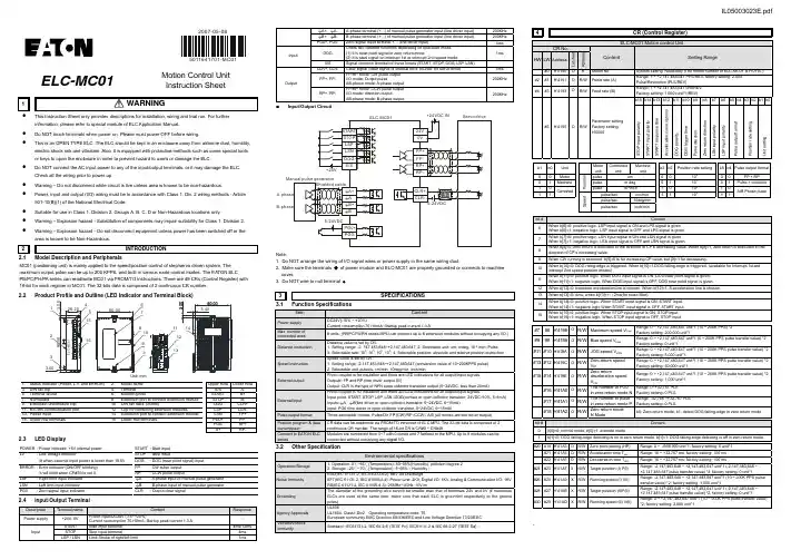
5011641701-MC012007-05-08ELC-MC01Motion Control UnitInstruction Sheet1WARNING•This Instruction Sheet only provides descriptions for installation, wiring and trial run. For furtherinfromation, please refer to special module of ELC Application Manual.•Do NOT touch terminals when power on. Please must power OFF before wiring.•This is an OPEN TYPE ELC. The ELC should be kept in an enclosure away from airborne dust, humidity,electric shock risk and vibration. Also, it is equipped with protective methods such as some special toolsor keys to open the enclosure in order to prevent hazard to users or damage the ELC.•Do NOT connect the AC input power to any of the input/output terminals, or it may damage the ELC.Check all the wiring prior to power up.•Warning – Do not disconnect while circuit is live unless area is known to be non-hazardous.•Power, input and output (I/O) wiring must be in accordance with Class 1, Div. 2 wiring methods - Article501-10(B)(1) of the National Electrical Code.•Suitable for use in Class 1, Division 2, Groups A, B, C, D or Non-Hazardous locations only.•Warning – Explosion hazard - Substitution of components may impair suitability for Class 1, Division 2.•Warning – Explosion hazard - Do not disconnect equipment unless power has been switched off or thearea is known to be Non-Hazardous.2 INTRODUCTION2.1 Model Description and PeripheralsMC01 (positioning unit) is mainly applied to the speed/position control of step/servo driven system. Themaximum output pulse can be up to 200 KPPS, and built-in various route control modes. The EATON ELCPB/PC/PH/PA series can read/write MC01 via FROM/TO instrucitons. There are 49 CRs (Control Register) with16-bit for each register in MC01. The 32-bits data is composed of 2 continuous CR number.2.2 Product Profile and Outline (LED Indicator and Terminal Block)Unit: mm1. Status Indicator (Power, L.V. and ERROR)2. Model name Upper Row Lower Row3. DIN rail clip4. Terminal S/S A-5. Terminal layout6. Mounting hole START B+7. Nameplate 8. Extension port to connect extension module STOP B-9. Extension unit/module clip 10. DIN rail track (35mm) DOG CLR+11. RS-485 communication port 12. Clip for combining extension modules LSP CLR-13. Power input 14. Extension port to connect extension module LSN FP+15. Upper row terminals 16. Lower row terminals PG0+ FP-PG0-RP+A+RP-2.3 LEDDisplayPOWER : Power indicator, +5V internal power START : Start inputLV : Low voltage indicator STOP : Stop inputlit when external input power is lower than 19.5V DOG : DOG (near point signal) inputERROR : Error indicator (ON/OFF blinking). FP : CW pulse outputIt will blink when CR#39 is not 0. RP : CCW pulse outputLSP : Right limit input indicator ΦA : A-phase input of manual pulse generatorLSN : Left limit input indicator ΦB : B-phase input of manual pulse generatorPG0 : Zero signal input indicator CLR : Output clear signal2.4 Input/OutputTerminalDescription Terminal name Content ResponsePower supply +24V, 0VPower input/DC24V (-15~+20%)±Current consumption 7010mA; Startup peak current 1.3 A-InputSTART Start input terminal 4ms/12msSTOP Stop input terminal 4msLSP / LSN Limit Stroke of right/left limit 1msΦA+, ΦA- A-phase terminal (+, -) of manual pulse generator input (line driver input) 200KHzΦB+, ΦB- B-phase terminal (+, -) of manual pulse generator input (line driver input) 200KHzPG0+, PG0- Zero signal input terminal +, - (line driver input) 4msInputDOGOffers two different functions depending on operation mode.(1) It is near-point signal in zero return mode.(2) It is start signal on interrupt 1st or interrupt 2nd speed mode.1msS/S Signal common terminal of these Inputs (START, STOP, DOG, LSP, LSN) -OutputCLR+, CLR- Clear signal (clear signal of internal error counter for Servo drive) 4msFP+, FP-FP/RP mode: CW pulse outputI/O mode: Output pulseAB-phase mode: A-phase output200KHzRP+, RP-FP/RP mode: CCW pulse outputI/O mode: direction outputAB-phase mode: B-phase output200KHzInput/Output CircuitNote:1. Do NOT arrange the wiring of I/O signal wires or power supply in the same wiring duct.2. Make sure the terminals of power module and ELC-MC01 are properly grounded or connects to machinecover.3.3 SPECIFICATIONS3.1 FunctionSpecificationsItem ContentPower supplyDC24V(-15% ~ +20%)Current consumption 70±10mA; Startup peak current 1.3 AMax. number ofconnected axes8 units; (PB/PC/PA/PH series MPU can connect up to 8 extension modules without occupying any I/O.)Distance instructionDistance value is set by CR.1. Setting range: -2, 147,483,648~+2,147,483,647;2. Selectable unit: um, mdeg, 10-4 inch, Pulse3. Selectable rate: 100, 101, 102, 103;4. Selectable position: absolute and relative position instructionSpeed instructionSpeed value is set by CR.1. Setting range: -2,147,483,648~+2,147,483,647 (conversion value of 10~200KPPS pulse)2. Selectable unit: pulse/s, cm/min, 10deg/min, inch/minExternal outputPhoto coupler is for insulation and there are LED indications for all output/input signals.Outputs: FP and RP (line driver output 5V)Output: CLR is the type of NPN open collector transistor output (5~24VDC, less than 20mA)External inputPhoto coupler is for insulation and there are LED indications for all output/input signals.±Input point: START, STOP, LSP, LSN, DOG(contact or open collector transistor, 24VDC10%, 5±1mA)ΦΦInputs:A, B(line driver or open collector transistor, 5~24VDC, 6~15mA)Input: PG0 (line driver or open collector transistor, 5~24VDC, 6~15mA)Pulse output format Three selectable modes: Pulse/Dir, FP (CW)/RP (CCW), A/B (all modes are line driver output)Position program & datatransmissionCR data can be read/write via FROM/TO intruction of ELC MPU. The 32-bit data is composed of 2continuous CR number. The range of 16-bit CR is CR#0 ~ CR#48.Connect to EATON ELCseriesModules are numbered from 0~7 with 0 closet and 7 farthest to the MPU. Up to 8 modules can beconnected without occupying any digital I/O.3.2 OtherSpecificationEnvironmental specificationsOperation/Storage1. Operation: 0~55(Temperature), 50~95%(Humidity), pollution degree 2()℃℃℃℃2. Storage: -25~70(Temperature), 5~95%HumidityNoise ImmunityESD(IEC 61131-2, IEC 61000-4-2): 8KV Air DischargeEFT(IEC 61131-2, IEC 61000-4-4): Power Line: 2KV, Digital I/O: 1KV, Analog & Communication I/O: 1KVRS(IEC 61131-2, IEC 61000-4-3): 26MHz~1GHz, 10V/mGroundingThe diameter of the grounding wire cannot be smaller than that of terminals 24V and 0V (if numerousELCs are used at the same time, make sure that each ELC is grounded respectively to the groundpoles)Agency ApprovalsUL508UL1604, Class1,Div2 Operating temperature code: T5European community EMC Directive 89/336/EEC and Low Voltage Directive 73/23/EECVibration/ShockimmunityStandard: IEC61131-2, IEC 68-2-6 (TEST Fc)/ IEC61131-2 & IEC 68-2-27 (TEST Ea)4 CR (Control Register)ELC-MC01 Motion control UnitCR No.Content Setting RangeHW LW AddressLatchedAttribute#0H’4190 O R Model No. System setting, Read-only (The model number of ELC-MC01 is H’0110.)#2 #1H’4191 O R/W Pulse rate (A)Range: 1 ~ +2,147,483,647 PPS/REV, factory setting: 2,000Pulse/Revolution (PLS/REV)#4 #3H’4193 O R/W Feed rate (B)Range: 1 ~ +2,147,483,647 unit/REV,Factory setting: 1,000 (unit*1/REV)#5H’4195 O R/WParameter settingFactory setting:H’0000b15 b14 b13b12b11b10b9 b8 b7b6 b5b4b3b2b1b0STOPinputpolaritySTARTinputpolaritySTARTresponsetimeAccelerationcurveoptionsDOGpolarityDOGtriggertimePulsedirectionZeroreturndirectionLSNinputpolarityLSPinputpolarityPulseoutputformatPositionratesettingUnitsettingb1 b0UnitMotorunitCombinedunitMachineunitb3b2Position rate setting b5b4Pulse output format0 0 MotorPosition pulse um 01000 0 FP + RP0 1 Machine pulse mdeg 0 1 1010 1 Pulse + direction1 0Combinedpulse 10-4inch 10 102 1A/B Phase pulse1 1Speedpulse/sec cm/min11 103 11pulse/sec 10deg/minpulse/sec inch/minbit # Content6When b[6]=0: positive logic. LSP input signal is ON and LPS signal is given.When b[6]=1: negative logic. LSP input signal is OFF and LPS signal is given.7When b[7]=0: positive logic. LSN input signal is ON and LSN signal is given.When b[7]=1: negative logic. LSN input signal is OFF and LSN signal is given.8When b[8]=0: zero return is executed to the direction of CP’s decreasing value. When b[8]=1, zero return is executed to thedirection of CP’s increasing value.9 When CW running is executed, b[9]=0 is for increasing CP value, but [9]=1 for decreasing.10When b[10]=0: DOG rising-edge is triggered. When b[10]=1,DOG falling-edge is triggered. (available for Interrupt 1st andinterrupt 2nd speed position modes)11When b[11]=0: positive logic. When DOG input signal is ON, DOG near point signal is given.When b[11]=1: negative logic. When DOG input signal is OFF, DOG near point signal is given.12 When b[12]=0: trapezoid acceleration line is chosen. When b[12]=1, S acceleration line is chosen.13 When b[13]=0: 4ms; when b[13]=1: 12ms(for noise filter).14When b[14]=0: positive logic. When START input signal is ON, START input.When b[14]=1: negative logic When START input signal is OFF, START input.15When b[15]=0: positive logic. When STOP input signal is ON, STOP input.When b[15]=1: negative logic. When STOP input signal is OFF, STOP input.#7#6H’4196 O R/W Maximum speed V max Range: 0 ~ +2,147,483,647 unit*1 (10 ~ 200K PPS) *2Factory setting: 200,000 unit*1#9#8H’4198 O R/W Bias speed V bias Range: 0 ~ +2,147,483,647 unit*1 (0 ~ 200K PPS pulse transfer value) *2Factory setting: 0 unit*1#11#10H’419A O R/W JOG speed V JOG Range: 0 ~ +2,147,483,647 unit*1 (10 ~ 200K PPS pulse transfer value) *2Factory setting: 5,000 unit*1#13#12H’419C O R/W Zero return speedV RTRange: 0 ~ +2,147,483,647 unit*1 (10 ~ 200K PPS pulse transfer value) *2Factory setting: 50,000 unit*1#15#14H’419E O R/WZero returndeceleration speedV CRRange: 0 ~ +2,147,483,647 unit*1 (10 ~ 200K PPS pulse transfer value) *2Factory setting: 1,000 unit*1#16H’41A0 O R/W The number of PG0in zero return mode NRange: 0~+32,767 PLSFactory setting: 0 PLS#17H’41A1O R/W The number of pulsein zero return mode PRange: -32,768 ~+32,767 PLSFactory setting: 0 PLS#18H’41A2O R/W Zero return modeH Modeb0: Zero return mode, b1: detect DOG falling-edge in zero return modebit #Content0 b[0]=0: normal mode, b[0]=1: override mode1 b[1]=0: DOG falling-edge detecting is on in zero return mode. b[1]=1: DOG falling-edge detecting is off in zero return mode.#20#19H’41A3 O R/W Zero point setting (HP) Range: 0 ~ ±999,999 unit*1; factory setting: 0 unit*1#21H’41A5 O R/W Acceleration time T acc Range: 10 ~ +32,767 ms; factory setting: 100 ms#22H’41A6 O R/W Deceleration time T dec Range: 10 ~ +32,767 ms; factory setting: 100 ms#24#23H’41A7 X R/W Target position (I) P(I)Range: -2,147,483,648 ~ +2,147,483,647 unit*1 (-2,147,483,648 ~+2,147,483,647 pulse transfer value) *2; factory setting: 0 unit*1#26#25H’41A9 X R/W Running speed (I) V(I)Range: -2,147,483,648 ~ +2,147,483,647 unit*1 (10 ~ 200K PPS pulsetransfer value) *2; factory setting: 1,000 unit*1#28#27H’41AB X R/W Target position (II)P(II)Range: -2,147,483,648 ~ +2,147,483,647 unit*1 (-2,147,483,648 ~+2,147,483,647 pulse transfer value) *2, factory setting: 0 unit*1#30#29H’41AD X R/W Running speed (II) V(II)Range: 0 ~ +2,147,483,647 unit*1 (10 ~ 200K PPS pulse transfer value)*2, factory setting: 2,000 unit*1.The ELC can be secured to a cabinet by using the DIN rail that is 35mm high with a depth of 7.5mm. When mounting the ELC on the DIN rail, be sure to use the end bracket to stop any side-to-side motion of the ELC, thus to reduce the chance of the wires being pulled loose. At the bottom of the ELC is a small retaining clip. To secure the ELC to the DIN rail, place it onto the rail and gently push up the clip.Notes:1. Please use 22-16AWG (1.5mm) wiring (either single or multiple core) for I/O wiring terminals.The specification for the terminals is as shown on the left. ELC terminal screws should betightened to 1.95 kg-cm (1.7 lb-in). Use Copper Conductor Only, 60/75 °C.2. I/O signal wires or power supply should not run through the same multi-wire cable orconduit.#31 H’41AF X R/WRunning instructionfactory setting: H’0000b15 b14 b13 b12 b11 b10 b9 b8 b7 b6 b5 b4 b3 b2b1 b0--CLRoutput(On/Off)CLRsignaloutputmode-Currentposition=-SoftwareSTARTABS/RELCoordinateZeroreturnstartJOG-JOG+CCWpulseSTOPCWpulseSTOPSoftwareSTOPErrorresetbit # Content Action7 When b[7]=0, it is absolute position. When b[7]=1, it is relative position. 0/18 Whenb[8]=01, start running by the work mode of CR#32.→0t110 Whenb[10]=01, current position (CP) is cleared to 0.→0t112When b[12]=0, CLR outputs 130ms to Servo when zero return is completed. It is the clear signal for servointernal error counter.When b[12]=1, CLR is common output point and the status(On/Off) is controlled by b[13].0/113 When b[13]=0, CLR output is Off. When b[13]=1, CLR output is On. 0/1#32 H’41B0 ╳R/WWork modeFactory setting:H’0001b15 b14 b13 b12 b11~b9 b8 b7 b6 b5 b4 b3 b2 b1b0--Currentposition:CR34,33;currentspeed:CR36,35;displayunit:Æpulse,1ÆunitReturntofactorysettingMASKsettingLSP/LSNstopmodeManualpulsegeneratorrangelimitationSTOPmodeManualpulsegeneratorinputoperationVariablespeedoperationmodestartInterrupt2nd-speedpositionmodestart2nd-speedpositionmodestartInterrupt1st-speedpositionmodestart1st-speedpositionmodestart5 When b[5]= 01, manual pulse generator input is started. Please refer to the setting of CR#40~#46.→6b[6]=0: When STOP is input, motor will decelerate to stop under running mode. When rerun instruction is received, motorwill neglect the uncompleted distance and directly go executing the next position instruction.b[6]=1: When STOP is input, motor will decelerate to stop under running mode. When rerun instruction is received, motorwill keep executing the uncompleted distance of previous instruction and then execute next position instruction.7b[7]=0: The output pulse of manual pulse generator is unlimited.b[7]=1: The output pulse of manual pulse generator is limited between P(I) and P(II). When the output pulse is out of therange, it will decelerate and then stop outputting.8b[8]=0: When motor is running, it will decelerate to stop if LSP/LSN signal is received.b[8]=1: When motor is running, it will stop immediately if LSP/LSN signal is received.9~11MASK setting (1st-speed operation, 2nd-speed operation, interrupt 1st-speed operation, interrupt2nd-speed operation)b[11~9]=K0(000) or other value: NO MASK function.b[11~9]=K1(001) : the rising-edge of input terminal A±will trigger MASK.ΦΦΦΦb[11~9]=K2(010) : the falling-edge of input terminal A±will trigger MASK.b[11~9]=K3(011) : the rising-edge of input terminal B±will trigger MASK.b[11~9]=K4(100) : the falling-edge of input terminal B±will trigger MASK.12 b[12]=1: All parameters return to factory setting.13b[13]=0: current position (CR34, 33) and current speed (CR36, 35). Display unit: pulse.b[13]=1: current position (CR34, 33) and current speed (CR36, 35). Display unit: unit.#34 #33 H’41B1 X R/WCurrent position CP(PLS)Range display: -2,147,483,648~+2,147,483,647 PLSFactory setting: 0 PLS#36 #35 H’41B3 X R/WCurrent speed CS(PPS)Range display: 0 ~ +2,147,483,647 PPSFactory setting: 0 PPS#37H’41B5X R/WCommunicationaddress and Baud ratesettingRS-485 communication address setting: setting range 01~225; factorysetting K1.Baud rate setting: 4800, 9600,19200, 38400, 57600, and 115200 bps.ASCII mode data format is 7Bit, even bit and 1 stop bit (7 E 1). RTU modedata format is 8Bit, even bit and 1 stop bit (8, E, 1)b0: 4800 bps(bit/sec.), b1: 9600 bps(bit/sec.) (factory setting)b2: 19200 bps(bit/sec.), b3: 38400 bps(bit/sec.)b 4: 57600 bps(bit/sec.), b 5: 115200 bps(bit/sec.)b6: reserved, b7: 0 for RTU, 1 for ASCII mode,b8~b15: communication address#38 H’41B6 O R/WExecution statusfactory setting:H’XXXXb15b14b13b12b11b10b9b8b7b6b5b4b3b2b1b0-----MPGinputdownwardMPGinputupward-RoutepausedindicationPositioncompletedindicationErroroccurredflagCPvalueoverflowZeroreturnisdoneCCWpulseisoutputtingCWpulseisoutputtingStatusindicationbit # Content0 When b[0]=0, system is ready. When b[0]=1, MC01 is executing position control mode (Pulse is outputting).1 When b[1]=1, CW pulse is outputting.2 When b[2]=1, CCW pulse is outputting.3When b[3]=1, zero return is completed and b[3] will be cleared by user-defined program. When MC01 is power on again, b[3]will be cleared to 0 automatically.4When b[4]=1, “Current position CP(PLS)”(CR#34, #33) of 32 bit will overflow. When MC01 is power on again or complete zeroreturn, b[4] will be cleared to 0 automatically.5 When b[5]=1, MC01 error occurred. Error code is stored in CR#39.6When MC01 starts executing zero return or error reset (only when error occurred), it will clear b[6] to 0. When zero return orposition control is completed, it will set b[6] to 1.7When MC01 is running and STOP status is on, MC01 will stop output and b[7] will be set to 1. It means that MC01 is pausedand it will execute the uncompleted route and b[7] will be cleared to 0 after STOP status is off.9 When b[9]=1, it means manual pulse generator inputs with counting upward.10 When b[10]=1, it means manual pulse generator inputs with counting downward.#39H’41B7 X R ErrorcodePlease refer to “Error Code & Troubleshooting” for detail. Factory setting:H’0000#40H’41B8 X R/WElectronic gearingnumerator of MPGinputPlease refer to the following explanationFactory setting: H’1#41H’41B9 X R/WElectronic gearingdenominator of MPGinputPlease refer to the following explanationFactory setting: H’1*1: Unit setting varies based on b0 and b1 setting of CR#5.*2: Use max. pulse output if upper limit is exceeded. Use min. pulse output if lower limit is exceeded.z CR#0~CR48: user can use the corresponding addresses H4190~41C0 to read/write data via RS-485 communication.1. Baud rate supportive: 4,800, 9,600, 38,400, 57,600, and 115,200 bps.2. Modbus ASCII/RTU: ASCII mode is 7Bit, even bit and 1 stop bit (7,E,1). RTU mode is 8Bit, even bit and 1 stop bit (8, E, 1).3. Function code: 03H for read data from CR; 06H for write one WORD in CR; 10H for write many WORDs in CR.5 INSTALLATION & WIRINGTo remove it, pull down the retaining clip and gently pull the ELC away from theDIN rail. As shown on the right:When installing the ELC, make sure that it is installed in an enclosure withsufficient space (as shown on the right) to its surroundings so as to allow heatdissipation.1. Installation of the DIN rail2. Wiring。

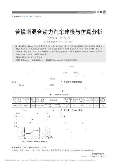
混合动力汽车动力系统的仿真与设计【摘要】本文介绍了混合动力汽车动力系统的基本设计方法,根据设计的性能要求对动力系统参数进行了设计,用电动汽车仿真软件ADVISOR对整车性能进行了仿真计算,验证了参数设计的合理性。
【关键词】混合动力汽车;动力系统;仿真;设计一、前言新能源汽车的发展是我国汽车行业的战略性发展方向。
在新能源汽车中,混合动力汽车继承了石油燃料高比能量和高比功率的优点,弥补了纯电动汽车续驶里程短的不足,使其成为当前新能源汽车领域最为切实可行的方案[1]。
混合动力汽车设计的过程中,动力系统的参数设计是其关键部分,本文针对动力系统相关参数的设计与计算,讨论了混合动力汽车动力系统参数设计的一般思路和方法。
二、混合动力汽车动力系统参数设计1.发动机参数设计发动机是混合动力汽车的主要动力来源,因此,发动机的参数选择是整个动力系统参数设计的重要部分。
对发动机参数的设计主要工作是对发动机功率的选择。
如果发动机功率选择过大,汽车的燃油消耗就会严重,经济性能差;如果发动机功率选择较小,后备功率就小,动力性能不足。
发动机功率的选择是由汽车在单驱动工况下行驶的最大速度及其爬坡度来决定的,即:其中,Pemax为发动机最大功率;为传动系效率;为最高车速;m为汽车的总质量;为滚动阻力系数;为空气密度;CD为空气阻力系数;A为迎风面积。
由于混合动力汽车发动机提供的是汽车正常行驶时的平均功率,因此,发动机功率的选择主要是根据汽车匀速行驶的工况下功率的值,使发动机工作在经济性能最好的区域,用下式计算:其中,Pe为汽车正常行驶时的功率;为汽车的平均行驶速度。
2.电机参数设计混合动力汽车使用的电机具有这样的特性:电机以小于额定转速工作时,处于恒定转矩的工作模式,反之,处于恒定功率的工作模式。
电机本身的质量、尺寸、损耗等因素都直接影响着最高转速,对传动系尺寸的大小也有较大的影响。
电机的最高转速与额定转速的比值,称为电机扩大恒功率区系数β。

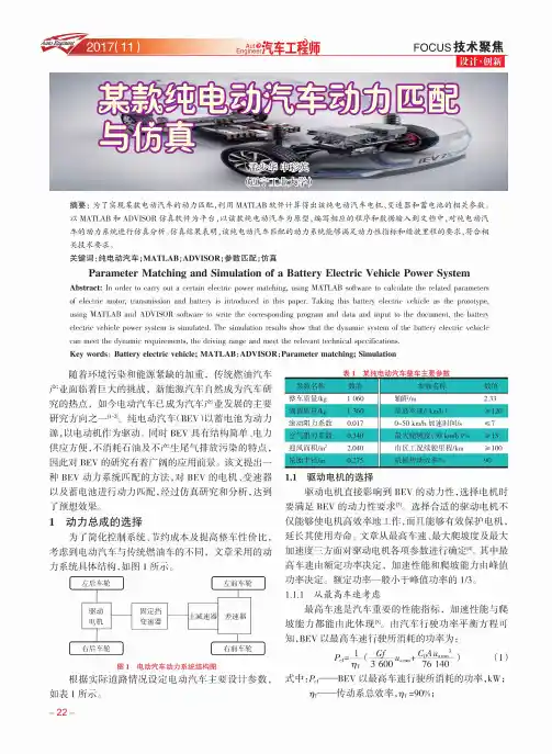
FOCUS 技术聚焦设计•创新摘要:为了实现某款电动汽车的动力匹配,利用M ATLAB 软件计算得出该纯电动汽车电机、变速器和蓄电池的相关参数。
以M ATLAB 和A D V ISO R 仿真软件为平台,以该款纯电动汽车为原型,编写相应的程序和数据输入到文档中,对纯电动汽 车的动力系统进行仿真分析。
仿真结果表明,该纯电动汽车匹配的动力系统能够满足动力性指标和续驶里程的要求,符合相 关技术要求。
关键词:纯电动汽车;MATLAB; ADVISOR ;参数匹配;仿真Parameter Matching and Simulation of a Battery Electric Vehicle Power SystemAbstract : In order to carry out a certain electric power matching, using MATLAB software to calculate the related parametersof electric motor, transmission and battery is introduced in this paper. Taking this battery electric vehicle as the prototype, using MATLAB and ADVISOR software to write the corresponding program and data and input to the document, the battery electric vehicle power system is simulated. The simulation results show that the dynamic system of the battery electric vehicle can meet the dynamic requirements, the driving range and meet the relevant technical specifications.Key words : Battery electric vehicle; MATLAB ;ADVISOR;Parameter matching; Simulation随着环境污染和能源紧缺的加重,传统燃油汽车 产业面临着巨大的挑战,新能源汽车自然成为汽车研 究的热点,如今电动汽车已成为汽车产业发展的主要 研究方向之一[1-]。
能源控制器Ⅰ型使用说明书青岛东软载波科技股份有限公司能源控制器类型标识代码分类说明NC X X X X-XXXX 能源控制器场景远程通信本地通信总线通信产品代号NC-能源控制器1-公变2-专变1-4G2-5G0-无1-HPLC2-微功率无线3-双模1-RS-4852-M-bus3-CAN由不大于8位的英文字母和数字组成。
英文字母可由生产企业名称拼音简称表示,数字代表产品设计序号能源控制器的功能模块类型标识代码分类见下表。
功能模块类型标识代码分类说明G X X X X-XXXX功能模块功能模块类型功能模块类型属性接口数量温度级别产品代号G-功能模块K-控制模块X-遥信模块B-本地通信模块Y-远程通信模块M-模拟量采集模块T-其他功能模块类型无补充属性,则为X;本地通信模块:Z-窄带电力线载波H-HPLCJ-微功率无线S-双模通信模块(载波&无线)M-MBUS通信模块R-RS485通信模块C-CAN通信模块T-其它信道远程通信模块:2-无线公网2G3-无线公网3G4-无线公网4G5-无线公网5GA-230MHz专网L-以太网有线网络N-公共交换电话网F-光纤有线网络T-其他信道多功能组合模块类型属性定义为:Z。
对外物理接口数量:1~9-1~9路物理接口1-C12-C23-C34-Cx由不大于8位的英文字母和数字组成,必须包含版本信息。
英文字母可由生产企业名称拼音简称表示,数字代表产品设计序号尊敬的用户:首先衷心感谢您选择青岛东软载波科技股份有限公司的产品。
青岛东软载波科技股份有限公司成立于1993年6月,2011年2月在创业板上市,现已形成以智能制造为基础,芯片设计为源头,能源互联网与智能化应用两翼齐飞的产业布局。
公司发展战略是以集成电路设计为基础,开展以融合通信为平台的技术研发;布局“芯片、软件(模组)、终端、系统、信息服务”产业链,聚焦能源互联网、智能化应用这两个战略新兴领域,打造国际一流企业。

策略仿真2023-11-04CATALOGUE 目录•并联混合动力汽车概述•能量控制策略仿真模型•并联混合动力汽车能量管理策略仿真•仿真结果分析•并联混合动力汽车能量控制策略仿真的应用前景01并联混合动力汽车概述并联混合动力汽车(Parallel Hybrid Electric Vehicle,简称PHEV)是一种同时配备发动机和电动机的汽车,通过并联连接发动机和电动机,以实现动力的混合输出。
并联混合动力汽车的结构包括发动机、电动机、电池、变速器、驱动桥等主要部件。
并联混合动力汽车的定义与结构并联混合动力汽车的能源管理策略并联混合动力汽车的能源管理策略主要包括电量消耗模式、电量保持模式和电量补充模式。
电量消耗模式是指优先使用电池能量,当电池电量低于一定阈值时,发动机启动并带动发电机为电池充电。
电量保持模式是指保持电池电量恒定,发动机和电动机协同工作,以满足行驶需求。
电量补充模式是指当电池电量不足时,发动机带动发电机为电池充电,同时电动机辅助驱动车辆行驶。
并联混合动力汽车的发展趋势是向高效、环保、节能方向发展。
未来并联混合动力汽车将采用更高效的发动机、更先进的电池技术以及更智能的能源管理系统,以提高能源利用效率,减少排放,提高车辆性能。
并联混合动力汽车的发展趋势02能量控制策略仿真模型基于MATLAB/Simulink平台利用MATLAB/Simulink软件平台,构建并联混合动力汽车能量控制策略仿真模型。
模型参数设置根据实际车辆参数和性能要求,设置仿真模型的参数,如发动机、电池、电机等部件的参数。
模型结构构建通过Simulink模块库,构建仿真模型的各个组成部分,包括动力系统、控制系统、能量管理系统等。
实验验证方法通过实验测试的方法,对仿真模型进行验证,比较仿真结果与实际车辆性能的差异。
验证结果分析根据实验验证结果,对仿真模型进行修正和优化,提高模型的准确性和可靠性。
模型验证原则根据实际车辆的运行特性和性能要求,对仿真模型进行验证,确保模型的准确性和可靠性。
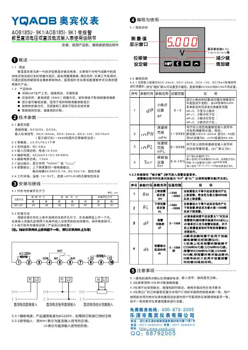
AOB185U-9K1/AOB185I-9K1带报警数显直流电压或直流电流输入表使用说明书安装、使用产品前,请阅读使用说明书概述编程与使用注意事项技术参数安装与接线1.1用途数显直流表为新一代经济型数显安装式电表,主要用于对电气线路中的直流电压电流进行实时测量与指示,具有测量精度高、稳定性好、长期工作免调校、可通过面板按键现场设置参数等特点,是原指针式仪表或普通数字式仪表的理想换代产品。
1.2产品特点●采用SMT 生产工艺,线路简洁、可靠性高●交流采样、测量方式,波形畸变不影响测量准确度●显示值可编程设置,适用于各种规格电量参数显示●独特的安装方式,无须借助工具即可轻松完成安装●智能表的性能、普通表的价格。
真有效值()RMS 2.1量程范围输入标准信号:DC0~20mA 、DC4~20mA 、DC0~10V 、DC75mV(显示值可199992.2%FS 2采样速率:.42.5AC220V 10%50/60Hz 2.632.7HHHH LLLL 2.8在~范围内任意编程设定)准确度:±0.5±1个字.3约1.5次/s2输入回路功耗:电流<0.5VA辅助电源:±辅助电源功耗:VA溢出指示:显示字符“”或“”报警输出:上下限报警同一继电器输出,触点容量AC250V/0.1A 、DC 30V/1A ,阻性负载<3.1外形与安装开孔尺寸单位:mm3.2安装方法根据仪表外形在上表中选择对应的开孔尺寸,在安装屏面上开一个孔,仪表嵌入安装孔后将两个夹持件放入仪表壳体的夹持槽内,用手推紧即可。
3.3端子排列与接线说明(产品后示接线图)3.3.1辅助电源:产品通用电源为AC220V ,如需其它电源订货时注明4.2编程说明仪表输入规格为、DC0~10V 、DC75mV 标准信号进行测量时,按住“增加”键可设置显示量程。
2s 5.1通电前请再次确认仪表辅助电源、输入信号、接线是否正确。
5.2仪表需预热15分钟才能准确测量5.3仪表不应受到敲击、碰撞和剧烈振动,使用环境应符合技术要求5.4仪表出厂时已将量程设置为与用户订货时所提供的规格参数一致,用户使用前应再次核对仪表的量程设定值与用户所配用的互感器规格是否一致。

并联混合动力汽车动力总成参数匹配与仿真
王国海;韩以伦
【期刊名称】《机械设计与制造》
【年(卷),期】2008(000)007
【摘要】根据电辅助控制策略特点,以满足整车动力性能为前提,使用以MATLABR2006a为平台的ADVISOR2002仿真软件,对并联混合动力汽车发动机参数、电机参数选择及能源匹配进行了仿真研究.利用ADVISOR2002软件,建立其仿真模型,在CYC_ECE_EUDC循环工况下得到其动力性、燃油经济性及一些重要性能曲线.最后得出结论:整个设计、建模和仿真基本达到预期设计目标.
【总页数】3页(P100-102)
【作者】王国海;韩以伦
【作者单位】山东科技大学,机械电子工程学院,物流与车辆工程系,青岛,266510;山东科技大学,机械电子工程学院,物流与车辆工程系,青岛,266510
【正文语种】中文
【中图分类】TH16;U46
【相关文献】
1.基于CRUISE并联式HEV动力总成参数匹配与仿真(续Ⅰ) [J], 阮晓东;牛礼民;叶李军
2.基于CRUISE并联式HEV动力总成参数匹配与仿真(续Ⅰ) [J], 阮晓东;牛礼民;叶李军;
3.基于CRUISE并联式HEV动力总成参数匹配与仿真(续2) [J], 阮晓东;牛礼民;叶
李军
4.基于CRUISE并联式HEV动力总成参数匹配与仿真(续2) [J], 阮晓东;牛礼民;叶李军;
5.插电式并联混合动力汽车参数匹配与仿真 [J], 汤海洋;张冰战;李开放
因版权原因,仅展示原文概要,查看原文内容请购买。
增程式电动汽车的动力参数匹配与性能仿真周亚洲;牛礼民;杨洪源;尹然【摘要】In order to convert a battery electric vehicle into an extended-range electric vehicle, by analyzing the working patterns and principles of range extender, parameters of engine and generator of the range extender's were matched, and reasonable design parameters were obtained. With the co-simulation platform of MATLAB/Simulink and ADVISOR, the battery electric vehicle and the extended-range electric vehicle were simulated in the same driving cycle (CYC_UDDS) respectively. Simulation results show that the driving range of the extended-range electric vehicle reaches 177.8 km, meanwhile its dynamic performance and fuel efficiency can be controlled within an appropriate range, which indicates that the modification scheme is reasonable and effective, and it provides the reference for the transformation test and vehicle road test.%为将一款纯电动汽车改装为增程式电动汽车,通过对増程器工作模式和原理的分析,对増程器的发动机与发电机参数进行匹配,得出合理的设计参数.结合MATLAB/Simulink与ADVISOR软件平台对改装前后的整车在相同循环工况(CYC_UDDS)下进行对比仿真分析.结果显示,改装后的增程式电动汽车续驶里程达177.8 km,且整车的动力性能与燃油经济性控制在合理的范围内,表明文中所提纯电动汽车改装方案是可行、有效的,为后续实车改造和整车路试实验提供参考依据.【期刊名称】《安徽工业大学学报(自然科学版)》【年(卷),期】2016(033)004【总页数】6页(P378-383)【关键词】增程式;续驶里程;参数匹配;仿真分析【作者】周亚洲;牛礼民;杨洪源;尹然【作者单位】安徽工业大学机械工程学院,安徽马鞍山243032;安徽工业大学机械工程学院,安徽马鞍山243032;安徽工业大学机械工程学院,安徽马鞍山243032;安徽工业大学机械工程学院,安徽马鞍山243032【正文语种】中文【中图分类】U469.72能源危机和环境污染问题愈发突出,致使能源消耗较大的汽车行业的发展日益受到限制,因此开发新能源汽车已成为各国汽车公司的共识。
ABEGG 变频器参数菜单一. TRAVELLING (速度)V-1=0.050 m/s 爬行速度V-2=1.17 m/s 单层速度V-3=2.00 m/s 最高速度V-Z=0.30 m/s 检修速度V-ZE1=0.50 m/s 校正速度V-ZE2=0.03 m/sV-ZE3=0.03 m/s二.ACCELERATING (加速度)A_POS=0.80m/s2 加速度R-POS1=57% 加速度开始段R-POS2=57% 加速度结束段三.DECELERATING (减速度)A-NEG=0.80 m/s2 减速度R-NEG1=57% 减速度开始段R-NEG2=90% 减速度结束段S-DI3=0 S-DI2=0 S-DI1=0S-ABH=OFF 依距离原则减速停车(对应于LME64的shaft copy 菜单时option子菜单中减速一项选用CONSIDER)四.CONTROLLER (比例积分调节器)K-nr=2.0 比例增益系数T-nr=100 调节器积分时间五.INSALL & MOTOR (马达铭牌参数)M&E ASM+Square 闭环矢量控制项motor & encoderV-NENN=2.00m/s 额定梯速在第3页,计算后输入以下看铭牌N-NENN=1039n/min 电机额定转数F-NENN=66 HZ 电机额定频数I-NENN=51 A 电机额定电流U-NENN=360 V 电机额定电压P-NENN=25 KW 电机额定功率TYP =star 电机绕组接法(星型)COS-PHI=0.87 功率因数AUTO =OFF 马达数据自动计数六. MOTOR-MODEL (马达内部数据)I_0=16AI_Rot=323msLs =0.094Sig=0.04七. INTERFACES (连接界面)GEBER=1024 旋编脉冲数SK-1 =Mot contactSK-2 =V<V_G1SK-3 =V<1.1*V_3ZE-2 =V_ZE2ZE-3 =OFFV-G1 =0.30m/sV-G2 =0.80m/sBR =OFFCO =ONMO-DR=LEFTCTRL =STANDARDCOPY =OFFLCD =ENGLISH八. ZA-INTERNStart_opti.: (启动参数) ANF-D=1FK_start=5.0 启动时比例增益系数S_ANF=10mm 滑动距离T_O =0.5sT_1 =0.3sT_2 =0.4s 抱闸吸合时间(启动冲击感主要调套此参数)T_3 =0.1sstop-opti ( 停止参数)T_4 =0.0sT_5 =0.3s 抱闸释放时间T_6 =0.2sError suppress.: (故障屏蔽)Mask1=83Mask2=0Msk3=0Status=10Control funet. (控制功能)T_gue=1.5s 旋编检测时间S-MB =0.50mU_ZK_MIN=380VU-ZK_MAX=750VTEMP_MAX=70℃T_VENT Auto+15sHardware-Check (硬件检测)TM4=63418Encoder input (编码器输入) Service:Eva with accuU_ACCU=120V 停电运行时提供的直流电压值CALCU LATOR (最达速度的计算) D=0.850m 曳引轮直径A=1:1 悬挂比J1=2 J2=65 曳引比V*=2.64 最大速度值九. SERVICE CHECK (服务及检测)TM4=63418Iq_max=112.0AC1 =83C2 =126ADC1 =3ADC2 =2CPU =1.95PHF =0SW_DATE=1911.1SW_FOC =1911.1PA_ERR =0调试步骤1.输入电机铭牌参数,AUTO=OFF2.进入ZA-INTERN中CALCU LATOR计算出V*最大速度3.修改V-NENN=V*AUTO=ON 按I键YES自动计算(等一会)再按I键YES自动计算(等一会)4.修改MOTOR-MODEL参数I-O=电机铭牌中ImI-ROT=电机铭牌中TCR5.调整速度,加减速度参数6.调整ZA-INTERN启动参数和CONTROLLER参数看舒适感.。
T h e i n f o r m a t i o n p r o v i d e d i n t h i s d o c u m e n t a t i o n c o n t a i n s g e n e r a l d e s c r i p t i o n s a n d /o r t e c h n i c a l c h a r a c t e r i s t i c s o f t h e p e r f o r m a n c e o f t h e p r o d u c t s c o n t a i n e d h e r e i n .T h i s d o c u m e n t a t i o n i s n o t i n t e n d e d a s a s u b s t i t u t e f o r a n d i s n o t t o b e u s e d f o r d e t e r m i n i n g s u i t a b i l i t y o r r e l i a b i l i t y o f t h e s e p r o d u c t s f o r s p e c i f i c u s e r a p p l i c a t i o n s .I t i s t h e d u t y o f a n y s u c h u s e r o r i n t e g r a t o r t o p e r f o r m t h e a p p r o p r i a t e a n d c o m p l e t e r i s k a n a l y s i s , e v a l u a t i o n a n d t e s t i n g o f t h e p r o d u c t s w i t h r e s p e c t t o t h e r e l e v a n t s p e c i f i c a p p l i c a t i o n o r u s e t h e r e o f .N e i t h e r S c h n e i d e r E l e c t r i c I n d u s t r i e s S A S n o r a n y o f i t s a f f i l i a t e s o r s u b s i d i a r i e s s h a l l b e r e s p o n s i b l e o r l i a b l e f o r m i s u s e o f t h e i n f o r m a t i o n c o n t a i n e d h e r e i n .Product data sheetCharacteristicsBMXAMM0600mixed analog I/O module X80 - 4 inputs - 2outputsProduct availability: Stock - Normally stocked in distribution facilityMainRange of product Modicon X80Product or component typeMixed analog I/O module Electrical connection 20 ways 1 connector Isolation between chan-nels Non isolated Input levelHigh level Analogue input number 4Analogue input typeCurrent 0...20 mA Current 4...20 mA Voltage +/- 10 V Voltage 0...10 V Voltage 0...5 V Voltage 1...5 VComplementaryAnalogue input resolution12 bits 0...20 mA 12 bits 0...5 V 12 bits 1...5 V 12 bits 4...20 mA 13 bits 0...10 V 14 bits +/- 10 V Permitted overload on inputs+/- 30 mA 0...20 mA +/- 30 mA 4...20 mA +/- 30 V +/- 10 V +/- 30 V 0...10 V +/- 30 V 0...5 V +/- 30 V 1...5 V Internal conversion resistor250 OhmPrecision of internal conversion resistor 0.1 % - 15 ppm/°CType of filter First order digital filtering by firmware Fast read cycle time 1 ms + 1 ms x number of channels used Nominal read cycle time 5 ms for 4 channelsMeasurement error0.25 % of full scale 0...20 mA 25 °C output 0.25 % of full scale 4...20 mA 25 °C output <= 0.35 % of full scale +/- 10 V 0...60 °C input <= 0.35 % of full scale 0...10 V 0...60 °C input <= 0.35 % of full scale 0...5 V 0...60 °C input <= 0.35 % of full scale 1...5 V 0...60 °C input <= 0.5 % of full scale 0...20 mA 0...60 °C input <= 0.5 % of full scale 4...20 mA 0...60 °C input <= 0.6 % of full scale +/- 10 V 0...60 °C output <= 0.6 % of full scale 0...20 mA 0...60 °C output <= 0.6 % of full scale 4...20 mA 0...60 °C output 0.25 % of full scale +/- 10 V 25 °C output 0.25 % of full scale +/- 10 V 25 °C input 0.25 % of full scale 0...10 V 25 °C input 0.25 % of full scale 0...5 V 25 °C input 0.25 % of full scale 1...5 V 25 °C input 0.35 % of full scale 0...20 mA 25 °C input 0.35 % of full scale 4...20 mA 25 °CTemperature drift100 ppm/°C +/- 10 V output100 ppm/°C 0...20 mA output100 ppm/°C 4...20 mA output30 ppm/°C +/- 10 V input30 ppm/°C 0...10 V input30 ppm/°C 0...5 V input30 ppm/°C 1...5 V input50 ppm/°C 0...20 mA input50 ppm/°C 4...20 mA inputRecalibration Factory calibrated on outputsInternal on inputsIsolation voltage1400 V DC between channels and ground1400 V DC between channels and bus750 V DC between group of I/O channels Output level High levelAnalogue output number2Analogue output type Current 0...20 mACurrent 4...20 mAVoltage +/- 10 VAnalogue output resolution11 bits, 0...20 mA11 bits, 4...20 mA12 bits, +/- 10 VConversion time<= 2 msMaximum conversion value+/- 11.25 V +/- 10 V output+/- 11.25 V +/- 10 V input0...30 mA 0...20 mA input0...30 mA 4...20 mA input+/- 11.25 V 0...10 V input+/- 11.25 V 0...5 V input+/- 11.25 V 1...5 V input0...24 mA 0...20 mA output0...24 mA 4...20 mA outputFallback mode PredefinedConfigurableProtective treatment TCOperating altitude0...6561.68 ft (0...2000 m)2000...5000 m with derating factorStatus LED RUN 1 LED green)Channel diagnostic 1 LED per channel green)ERR 1 LED red)I/O 1 LED red)Net weight0.34 lb(US) (0.155 kg)Power consumption in W 1.3 W 24 V DC typical2.8 W 24 V DC maximum0.35 W 3.3 V DC typical0.48 W 3.3 V DC maximum EnvironmentVibration resistance 3 gnShock resistance30 gnAmbient air temperature for storage-40…185 °F (-40…85 °C)Ambient air temperature for operation32…140 °F (0…60 °C)Relative humidity5…95 % 131 °F (55 °C) without condensation IP degree of protection IP20Directives2014/35/EU - low voltage directive2014/30/EU - electromagnetic compatibility2012/19/EU - WEEE directiveProduct certifications ULMerchant NavyRCMCSACEEACStandards EN 61131-2EN 61000-6-4EN 61000-6-2EN 61010-2-201Ordering and shipping detailsCategory18160 - MODICON M340Discount Schedule PC34GTIN00785901681823Package weight(Lbs)0.18 kg (0.39 lb(US))Returnability YesCountry of origin FROffer SustainabilitySustainable offer status Green Premium productREACh Regulation REACh DeclarationEU RoHS Directive Pro-active compliance (Product out of EU RoHS legal scope)EU RoHS Decla-rationMercury free YesRoHS exemption information YesChina RoHS Regulation China RoHS DeclarationEnvironmental Disclosure Product Environmental ProfileCircularity Profile End Of Life InformationWEEE The product must be disposed on European Union markets following specificwaste collection and never end up in rubbish bins.Contractual warrantyWarranty18 monthsDimensions DrawingsModules Mounted on RacksDimensions(1)With removable terminal block (cage, screw or spring).(2)With FCN connector.(3)On AM1 ED rail: 35 mm wide, 15 mm deep. Only possible with BMXXBP0400/0400H/0600/0600H/0800/0800H rack.Connections and SchemaWiring DiagramUx + pole input for channel x COMx - pole input for channel x U/IOx+ pole output for channel x COMOx - pole output for channel x *The current loop is self-powered by the output and does not request any external supply.。
ISG混合动力电动汽车控制策略仿真研究
李国斐;林逸;何洪文
【期刊名称】《计算机仿真》
【年(卷),期】2009(0)8
【摘要】控制策略是混合动力汽车的关键技术,直接影响混合动力汽车整车性能.ISG混合动力汽车中发动机和电机输出转矩在同轴上耦合,工作要求具有独特性.通过对驱动结构和工作要求分析,以优化整车动力性和燃油经济性为目标,提出了针对ISG混合动力系统的电辅助控制策略,制定了各行驶工况下的控制逻辑.建立了相关控制模型,在Advisor软件平台上对控制策略进行了仿真.仿真结果表明,提出的电辅助控制策略完全适用于ISG混合动力汽车,与传统汽车相比,整车动力性和燃油经济性均得到进一步提高.
【总页数】5页(P253-257)
【作者】李国斐;林逸;何洪文
【作者单位】北京理工大学机械与车辆工程学院,北京,100081;北京理工大学机械与车辆工程学院,北京,100081;北京理工大学机械与车辆工程学院,北京,100081【正文语种】中文
【中图分类】U469.72
【相关文献】
1.ISG轻度混合动力电动汽车控制策略的制定及仿真 [J], 王德伦;周荣宽
2.混合动力电动汽车模糊逻辑控制策略的研究与仿真 [J], 陈健;李彦;吴亚祥;廖荣
福
3.ISG轻度混合动力电动汽车控制策略的制定及仿真 [J], 王德伦;周荣宽;
4.并联混合动力电动汽车动态协调控制策略及仿真研究 [J], 严运兵;颜伏伍;杜常清
5.ISG混合动力电动汽车控制策略研究 [J], 周雅夫;连静;李启迪
因版权原因,仅展示原文概要,查看原文内容请购买。