张力控制器(LD-40PSU)
- 格式:pdf
- 大小:438.21 KB
- 文档页数:6

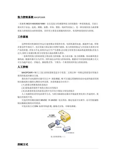
张力控制系统MAGPOWR(美塞斯MC01/400/830/1898)往往是张力传感器和张力控制器的一种系统集成,目前主要应用于冶金,造纸,薄膜,染整,织布,塑胶,线材等设备上,是一种实现恒张力或者锥度张力控制的自动控制系统,其作用主要是实现辊间的同步,收卷和放卷的均匀控制。
工作原理这种控制对机器的任何运行速度都必须保持有效,包括机器的加速、减速和匀速。
即使在紧急停车情况下,也应有能力保证被分切物不破损。
张力控制的稳定与否直接关系到分切产品的质量。
若张力不足,原料在运行中产生漂移,会出现分切复卷后成品纸起皱现象;若张力过大,原料又易被拉断,使分切复卷后成品纸断头增多。
一套典型的张力控制系统主要由张力控制器,张力读出器,张力检测器,制动器和离合器构成。
根据环路可分为开环,闭环或自由环张力控制系统;根据对不同卷材的监测方式又可分为超声波式,浮辊式,跟踪臂式等,下图为一个典型的闭环张力控制系统。
人工控制MAGPOWR <1ll人工张力控制系统是适合于收卷,点到点和一些特定的放卷应用场合使用的低成本解决方案.我们的手动电源供应器可以让f~ 淌除剩磁,15可以通过莫独特的皮向电流性能而用到制动器或离合器的完整的功率范围。
该系统最适合应用于:( 1 )需要自然锥角的收卷场合( 2 )卷装成形保持不变的点到点应用场合( 3 )从满卷到卷芯的放卷过程中允许有少量张力变化的场合人工电源供给采用电流调节方式,当离合器或制动器从环境温度变化到工作温度时,莫输出仍保持不变。
可选用带有跳结器的90VDC 和24VDC 电压供给,额定电流可以调节,还可匹配磁粉制动器满足榕的应用需求。
可选安装方式DIN 标准导轨(C E) .撞墙式安装,印刷电路板。
张力控制系统(3张)控制方式1、手动控制,在收料、放料或过程中不断调整离合器或制动器的扭矩,从而获得所需的张力,这就要求用户必须随时检查被控材料的张力,随时调节输出力矩,若用气动制动器或离合器时,手动控制器可直接选用精密调压阀,可使用户节约一定的设备成本,但仅适用于一些低速的复合机、挤出机、纺织机械等张力控制要求不高的场合。
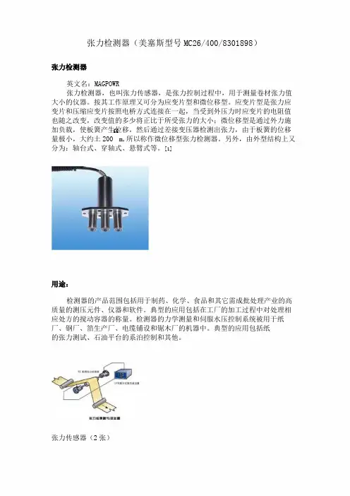
张力检测器(美塞斯型号MC26/400/8301898)张力检测器英文名:MAGPOWR张力检测器,也叫张力传感器,是张力控制过程中,用于测量卷材张力值大小的仪器。
按其工作原理又可分为应变片型和微位移型。
应变片型是张力应变片和压缩应变片按照电桥方式连接在一起,当受到外压力时应变片的电阻值也随之改变,改变值的多少将正比于所受张力的大小;微位移型是通过外力施加负载,使板簧产生位移,然后通过差接变压器检测出张力,由于板簧的位移量极小,大约土200“m,所以称作微位移型张力检测器。
另外,由外型结构上又分为:轴台式、穿轴式、悬臂式等。
[1]用途:检测器的产品范围包括用于制药、化学、食品和其它需成批处理产业的高质量的测压元件、仪器和软件。
典型的应用包括在工厂的加工过程中对处理相应处方的搅动容器的称量。
检测器的力学测量和伺服水压控制系统被用于纸厂、钢厂、箔生产厂、电缆铺设和锯木厂的机器中。
典型的应用包括纸 的张力测试、石油平台的系泊控制和其他。
张力传感器(2张)概述:MAGPOWR@的张力控制产晶范围很广,任何时候都能为您提供精确的张力监测产晶.这些产晶能够通过简易的组合,搭建出满足您需要的最理想的张力监测解决方案。
模拟显示相数字显示均可放大器可用于传输O-1OVDC或4-20mADC信号至PLC或马达驱动器可选安装方式:DIN标准导轨(CE),撞墙式安装,嵌入面板式安装仪表及配件:AST3P;AST3IS;WST3;GATE3S;TAD3;WIN3;deltaCOM;型号系列:称重检测器KOM-1系列KOM-1-1OKNKOM-1-2OKNKOM-1-5OKNKOM-1-1OOKNKOM-1-2OOKN称重检测器KOSD系列KOSD-1000KNKOSD-2OOOKN称重检测器KOSD-40系列KOSD-40-10KNKOSD-40-20KNKOSD-40-50KNKOSD-4O-1OOKNKOSD-40-200KN锅炉张力计PST系列PST-20KNPST-40KNPST-80KNPST-200KN钢丝绳张力检测器RTT系列10〜36mm纸带张力测量模块FMU系列纸带张力测量模块HTK系列纸带张力检测器KIP-1系列KIP-1-10KNKIP-1-20KN双轴纸带张力检测器HTU系列HTU-2KlbHTU-6KlbHTU-lOKlbHTU-20KlbHTU-9KNHTU-27KNHTU-45KNHTU-89KN检测器AST31S系列DIN导轨检测器AST3P系列DIN导轨张力传感器系统的工作原理:配料系统采用24位高精度A/D转换器。
尊敬的用户,您好!欢迎使用艾礼安电子围栏系统。
十分感谢您的支持!为了更方便的使用本产品,请您在使用前仔细阅读说明书,并按照说明书步骤操作,请注意说明书中提到的安全注意事项。
并请妥善保管本说明书,谢谢!安全注意事项使用本产品时需要注意的安全事项:1、在安装和使用本产品之前,应先对工作人员做好安全教育的技术培训。
2、为了产品安装以后的正常使用,产品的接地要求一定要严格按照说明书的要求进行。
3、请勿在易燃、易爆品周围使用该系统,特殊情况使用时,应保持安全距离。
4、请勿在雷雨天安装张力围栏系统。
5、请勿把张力围栏主机直接安装于潮湿,过高或过低温度环境中。
6、如出现异常情况,应先切断电源,并通知专业人员,请勿自行拆修,否则后果自负。
7、用户不得自行打开主机维修,否则我司不予保修。
8、本产品使用者,必须具有电器安全知识。
9、安装使用前必须阅读此说明书,熟悉本产品的正确使用方法并规范操作,否则由此产生的一切后果由使用者承担。
目录前言 (1)一、系统功能与特点 (2)、系统功能 (2)、系统优点 (2)、系统特点 (2)二、产品说明 (3)、产品设计依据 (3)、产品特性 (3)、张力主机技术参数 (3)、张力控制杆技术参数 (3)、产品接口说明 (4)三、张力式智能电子围栏系统图与工作原理 (5)、张力式智能电子围栏系统图 (5)、张力式电子围栏系统工作原理 (5)、张力式智能电子围栏前端连接示意图 (5)四、张力式电子围栏系统工作说明 (6)、张力式电子围栏启动说明 (6)、张力式电子围栏报警说明 (7)五、张力式电子围栏安装使用说明 (8)、防区划分 (8)、安装步骤 (8)六、张力式电子围栏前端设备简介 (10)、四道单防区控制杆、四道双防区控制杆 (10)、六道单防区控制杆、六道双防区控制杆 (10)、终端受力杆+万向底座 (11)、转向承力杆+万向底座 (11)、中间支撑杆+万向底座 (11)、一道万向轴承滑轮 (12)、张力弹簧 (12)、张力收紧器 (12)、束线器 (12)、多股张力线 (12)前言张力围栏系统是目前最先进的周界防盗报警系统,一般系统主要由张力围栏主机、前端控制杆及配件二大部分组成。
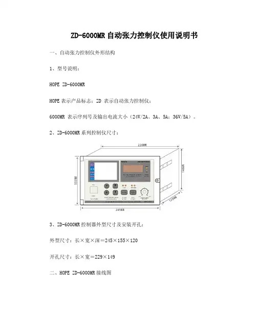
ZD-6000MR自动张力控制仪使用说明书一、自动张力控制仪外形结构1、型号说明:HOPE ZD-6000MRHOPE表示产品标志;ZD 表示自动张力控制仪;6000MR 表示序列号及输出电流大小(24V/2A、3A、5A;36V/5A)。
2、ZD-6000MR系列控制仪尺寸:3、ZD-6000MR控制器外型尺寸及安装开孔:外型尺寸:长×宽×深=245×155×120开孔尺寸:长×宽=229×149二、HOPE ZD-6000MR接线图接线时,拧开自动张力控制仪前面板上固定螺钉,将其打开。
与前面板固定的为电脑板,与电脑板用排线连接的为信号处理及输入输出接线板。
最下层为电源板,为整机提供驱动电源。
接线如下图三、恒张力工作原理自动恒张力控制系统适用于收卷、放卷、过程控制、同步控制等,广泛用于连续印刷、纺织、电线电缆、钢铝带、皮革等行业。
两台张力传感器检测出在线张力,由张力实测显示大小。
在学习状态下由电位器调节张力输出大小,达到合适张力时,按学习/自动键进入自动态,此时控制器完成低速建张并确定标准张力(即设定值)。
工作过程中实测值与设定值时刻在进行比较,当两者不等时,对输出进行智能PID调节,使磁粉离合器制动器或伺服电机改变力矩。
保证设定张力与测量张力相等。
四、控制器各部件名称及作用1、接线端子:连接张力检出器等输入输出连线。
详见接线图。
2、液晶显示器: 显示控制数据、完成参数设定。
3、四位数码显示:显示张力电流或电压的千分比。
4、自动状态指示灯:该灯亮表示机器运行在自动控制状态。
5、转速显示指示灯:表示机器转动快慢,由霍尔开关检测。
6、电源开关:控制总电源的通断。
7、功能参数设定区:有四个键,供设定参数用。
详见参数设定。
8、双功位转换键:双轴工作时作A/B轴切换,LED发光管作指示。
9、学习/自动键:(1)每更换一次不同的材料,须进行张力大小的学习,即获得设定张力,在学习状态下由电位器调整好张力大小,若认为该值合适,即可按下“学习/自动”键学习过程完成,张力设定值取得,同时进入自动状态。
()请务必在使用之前阅读5在打开控制器准备安装和接线之前要断开控制器电源至少要分钟。
正确的配置和安装是控制器正常运行的前提。
对以下几点要特别注意:●容许保护等级:保护接地,只有正确连接保护接地,才能减少外界电磁干扰。
●安装工作必须在无电状态下进行。
●与电网断开后,要等电容放电完毕,才可进行操作。
●不要让任何异物进入驱动器内。
●在使用前,要除去所有覆盖物,以防止装置过热。
●切勿在易燃易爆等危险环境中使用。
●请勿将该产品安装在高温、潮湿等恶劣环境下。
●请勿将产品直接安装在易受震动冲击的环境中。
T C 9000系列张力控制器是一种高精度数字式可以自动控制卷材张力的自动控制仪器,它可以控制材料的放卷、送料、牵引及收卷张力。
第一章产品概述1.1概述D/A0.1%/●采用高精度转换器,输出精度可达,张力控制更精确。
●可以直接驱动磁粉(电磁)离合器制动器,也可控制变频、伺服等。
●可以接收单路或双路传感器输入信号,自动标定。
●金属外壳,坚固美观,更具有很强的防电磁干扰功能。
●插拔端子,接线安装方便。
自动调零,●人性化界面设计,操作十分方便。
●多行液晶显示,中英文菜单,编程简单,方便明了。
●内有密码功能,可以避免误操作改变设定参数。
●带有储存盒,可以将各种参数进行备份。
1.2功能及特点[1]编程键:用这两个键可以进行各种菜单的选择或设定的确认。
返回键:按下此键可以返回到上一级菜单或返回到运行画面。
控制键确认键:进入编程菜单或确认设定参数。
手动控制模式键按下此键,控制器面板上手动指示灯()亮,控制器进入手动控制模式。
此时不受内部设定参数控制,按键键直接改变输出值。
自动控制模式键按下此键,控制器进入自动控制模式,此时面板上自动控制指示灯()亮,控制器处于自动运行状态,输出值受内部设定参数及、、控制。
在自动控制模式时,按键和键可以改变张力设定值。
控制输出、选择,重复按此键,输出则在之间切换。
数值设定刻度盘旋转刻度盘()用于调整设定参数的大小或选择菜单,其功能和键相同。
()请务必在使用之前阅读5在打开控制器准备安装和接线之前要断开控制器电源至少要分钟。
正确的配置和安装是控制器正常运行的前提。
对以下几点要特别注意:●容许保护等级:保护接地,只有正确连接保护接地,才能减少外界电磁干扰。
●安装工作必须在无电状态下进行。
●与电网断开后,要等电容放电完毕,才可进行操作。
●不要让任何异物进入控制器内。
●在使用前,要除去所有覆盖物,以防止装置过热。
●切勿在易燃易爆等危险环境中使用。
●请勿将该产品安装在高温、潮湿等恶劣环境下。
●请勿将产品直接安装在易受震动冲击的环境中。
T C 9000系列张力控制器是一种高精度数字式可以自动控制卷材张力的自动控制仪器,它可以控制材料的放卷、送料、牵引及收卷张力。
第一章产品概述1.1概述D/A0.1%/●采用高精度转换器,输出精度可达,张力控制更精确。
●可以直接驱动磁粉(电磁)离合器制动器,也可控制变频、伺服等。
●可以接收单路或双路传感器输入信号,自动标定。
●金属外壳,坚固美观,更具有很强的防电磁干扰功能。
●插拔端子,接线安装方便。
自动调零,●可以双路输出控制。
人性化界面设计,操作十分方便。
●多行液晶显示,中英文菜单,编程简单,方便明了。
●内有密码功能,可以避免误操作改变设定参数。
●带有储存盒,可以将各种参数进行备份。
进行●1.2功能及特点磁粉制动器(放卷)1.编程键2.LCD递增键递减键11.自动控制模式下图为张力控制器面板TC9000-LC213.数值设定刻度盘[1]编程键:用这两个键可以进行各种菜单的选择或设定的确认。
返回键:按下此键可以返回到上一级菜单或返回到运行画面。
控制键确认键:进入编程菜单或确认设定参数。
手动控制模式键按下此键,控制器面板上手动指示灯()亮,控制器进入手动控制模式。
此时不受内部设定参数控制,按键键直接改变输出值。
自动控制模式键按下此键,控制器进入自动控制模式,此时面板上自动控制指示灯()亮,控制器处于自动运行状态,输出值受内部设定参数及、、控制。
德国Tensometric张力计、传感器、放大器、夹紧装置介绍德国Tensometric作为对运行材料进行电子张力测量的专家拥有30多年的经验、灵活的团队和与客户的紧密联系。
超高的测量精度和可靠性、长期稳定性、精心设计、耐用可靠的系统使张力测量仪器与众不同。
除此之外,我们还为您提供特殊的生产、短的交货时间、快速维修服务和非常好的性价比。
专业的知识和效率在产品中得到了体现。
其中包括用于不同行业的不同操作区域的精密拉力计和摩擦计,用于生产细金线和带状电缆的质量保证。
产品应用于汽车工业、医学、造纸和纺织业、电线电缆行业、飞艇工业等领域。
1)拉力测量:拉力测量是一种现代质量保证方法。
张力计可靠而有效地监控生产机器对最佳值的遵守情况。
最大限度地减少了生产误差,降低了生产成本,优化了材料的使用。
生产监控的准确性和效率再高不过了。
张力计精确可靠地监测张力。
因此,几个分布式标准传感器在生产过程中提供的监控。
手持式:这些小型且易于管理的电子拉力测量仪器随时准备就绪,是短时间测量不可huo缺的。
我们的测量设备的特点是电流材料易于穿线。
显示器阻尼可以被激活,并在张力波动时提供稳定和平滑的显示。
因此,可以保证测量张力的直接读数。
电子拉力测量装置。
应用:纺织纱线、细线。
当前材料易于穿线。
小巧方便,随时准备,适用于短时间测量。
测量张力的直接读数。
显示阻尼可以被激活,即使在张力波动的情况下也能稳定平滑地显示。
按下按钮时,将保持最后显示的测量值。
参考型号:HANDY-TENS、HANDY-TENS VK、HANDY-TENS LC、HANDY-TENS LWL、Combi 490、Combi M600、DMS-TENS、MINI 710、KT871、M150、M1562) M 124和M 134系列是用于测量张力的紧凑型传感器。
通过其光滑、精确的滚珠轴承以及非常小的弹性纱线张力可以测量。
材料易于穿线,转动传感器。
通过外部精确的导辊,材料以限定的角度围绕测量辊被引导。
JZ990D41201AMITSUBISHI POWER AMPLIFIRECautions on Safety(Make sure to read this paragraph before using the unit.)Make sure to thoroughly read this instruction manual, techni-cal data, etc. before using the unit, and pay attention toassure safety while using the unit.In this manual, cautions on safety are classified into "DAN-GER" and "CAUTION".°important and it may lead to a serious result depending onthe situation. Make sure to observe every item.The unit is manufactured under severe quality control sys-tem. When applying the unit to a facility where a failure of theunit may lead to a serious accident or loss, however, system-atically install the backup or fail-safe function.Carefully store this instruction manual so that it can bereferred to at any time if necessary, and see to it that the enddisassembly, modification, etc. performed by a third party otherthan MITSUBISHI or a company specified by MITSUBISHI.Accordingly, ask a service network specified by MITSUBISHI forrepairs and disassemblies.The above cautions on safety and the specifications described inthe instruction manual and technical data are subject to changewithout prior notice.1.Functions and FeaturesThe power amplifire LD-40PSU is designed only for powderclutches/brakes and hysteresis clutches/brakes. This poweramplifire operates in a wide power range of 85 to 264 VAC, and isequipped with built-in control outputs of 24 VDC/3.8 A.1)Features(1) Switching regulator method(2) Operates in a wide power range of 85 to 264 VAC.(3) Constant voltage control method(4) External control signal(RC: Remote control ON/OFF input)(5) Digital display (4-digit, 7-segment LED)(6) Input for external variable resistor(SP: Analog signal input)(7) Protection against load short-circuit and short-circuitwarning indication (OC-LED)(8) Output two-step switching function(9) Power factor of 80% or more2)Major applications(1) Manual power supply unit controlled through the vari-able resistor on the panel surface.(2) Manual power supply unit controlled through an exter-nal variable resistor.• The output can be adjusted using an external variableresistor when the variable resistor provided on thepanel surface is made invalid and a variable resistor of500 to 2kΩ (1/2 W or more) is connected to the outputterminal (5V) and input terminal (SP-SN).(3) Power amplifier using an external voltage signal• The output can be adjusted using an external voltagesignal when the variable resistor provided on thepanel surface is made invalid and the voltage of 0 to 5V is input to the input terminal (SP-SN).(4) Output two-step switching function• The output in the output OFF condition can beadjusted within the range from 0 to 100%. The outputcan be switched in two steps using a knob or an exter-nal voltage signal.3)Panel configuration[1] Voltage adjusting variable resistor[2] [MODE] key--Changes over the adjustment mode.[3] Adjustment mode indicator LED (green)[4] Overcurrent detection indicator LED (red)[5] Power ON indicator LED (green)[6] 7-segment display[7] Voltage indicator LED (red)[8] Output voltage (V)/output percentage (%) displayselector key[9] Output percentage (%) indicator LED (red)[10] External variable resistor validity indicator LED(green)[11] [SET] key-----Determines data setting.[12] [ S ] key[13] [ T ] key[14] Output ON indicator LED (green)[15] Output ON/OFF selector switch2.Installation and Wiring1)Installationface or panel surface.POWER AMPLIFIRETYPE LD-40PSUINSTRUCTION MANUALThoroughly read this instruction manual, and then usethe unit correctly. Especially, make sure to read "Cau-tions on Safety" before using the unit.Carefully store this instruction manual, and see to it thatthe end user receives it.This printed matter is issued in March 2005. The specifi-cations are subject to change without prior notice.Manual number JZ990D41201Sub number ADate of preparation Nov. 2005ZJ-4065Aa)Installation on floor surfacemake valid the variable resistor on the panel surface, and make invalid the input signal for control.• valid.4)Changeover of output display• The output voltage (V) or output percentage (%) is dis-played on the 7-segment display [6].• Press the display selector key [8] to alternately select the output voltage (V) and output percentage (%).5)Output ON/OFF functiona)Use the output ON/OFF switch [15] on the panel sur-face or [RC] signal to set the output to ON or OFF.• When the [RC] signal is set to ON, the output is generated without regard to the setting of the out-put ON/OFF switch [15] on the panel surface.• When the [RC] signal is set to OFF , the output ON/OFF switch [15] on the panel surface becomes valid. Every time the output ON/OFF switch is pressed, the output is set to "ON → OFF → ON " alternately.• Stop timer setting range :7)[OC] is displayed on the 7-segment display [6], and [OC] and the overcurrent detection indicator LED [4] flicker alternately.• When the overcurrent detection indicator LED [4] lights, check the external wiring and release the short-circuit status.• After releasing the short-circuit status, turn off the power, wait for 30 seconds or more, and then turn on the power to recover the unit to the normal status.4.Adjustment1)Screen changeover method2)Changeover to the adjustment mode• While the power is ON, press and hold the [MODE] key [2] for 1 second or more to select the adjustment mode. At this time, the adjustment mode indicator LED [3] lights.• The output voltage value just before changeover to the adjustment mode is maintained.If the voltage adjusting variable resistor [1] or an external variable resistor is turned after the adjustment mode is selected, the output voltage changes accordingly. However, the value after change is not displayed on the 7-segment display [6].When the adjustment mode is finished, the output voltage value or output percentage value after change is displayed.• For finishing the adjustment mode, press and hold the [MODE] key [2] again for 1 second or more.• Press the display selector key in the adjustment mode to display the present output.(Note) If any key is not pressed for 10 seconds or more after the adjustment mode is selected, the normal mode is auto-matically selected.3)Functions of the keys on the panel surface -----------In the adjustment mode, each key has the following function.• [MODE] key [2]Press and hold this key for 1 second or more in the normal mode to select the adjustment mode. When the adjustment mode is selected, the adjustment mode indicator LED [3] lights.For selecting the normal mode after setting of the parameters is completed, press and hold this key for 1 second or more.• [S ] key [12]Use this key for selecting either of the adjustment items 1 to 3 in the adjustment mode. Every time this key is pressed, the adjustment item No. is changed in the order "3 → 2 → 1".After selecting an adjustment item, press this key to increase the set value. Press and hold this key for 2 seconds or more to automatically increase the set value.• [T ] key [13]Use this key for selecting either of the adjustment items 1 to 3 in the adjustment mode. Every time this key is pressed, the adjustment item No. is changed in the order "1 → 2 → 3".After selecting an adjustment item, press this key to decrease the set value. Press and hold this key for 2 seconds or more to automatically decrease the set value. • [SET] key [11]After selecting an adjustment item, press this key to determine the selected adjustment item and enable setting of a numeric value.After setting a numeric value, press this key to store the set value and return to the adjustment item selection status.•Press this key once in the adjustment mode to change over the display contents on the 7-segment display between the output voltage (V) monitoring and the output voltage adjustment (%) monitoring.If any key is not pressed for 5 seconds in the monitoring display status, the display contents automatically return to the status just before the display selector key is pressed. At this time, if the display selector key is in the numeric value set-ting status, the numeric value being set is canceled.If the display selector key is pressed again in the monitoring display status, the output voltage (V) monitoring and output voltage adjustment (%) monitoring are changed over alternately every time the display selector key is pressed.• [OUTPUT] key [14]This key turns on and off the output voltage between the PP and PN terminals.Every time this key is pressed, the output is set to "ON → OFF → ON" alternately.The RC signal input has higher priority. Even if this key is set to "output OFF", the output is ON while the RC signal input is ON.4)Adjustment method-----------Press and hold the [MODE] key [2] for 1 second or more to select the adjustment mode, and thenset the value of each item described below.a)OFS (output OFF ) setting• Set the voltage output while the output is set to OFF (while the OUTPUT LED [14] is extinguished).• When the output is set to OFF using the procedure described in 3-3), the voltage set here is output.• This function can be used for setting the weak exciting voltage of the powder clutch while the output is OFF .• Setting range-------0 to 100% ---------Initial value = 0% (100% = Maximum output voltage, approx. 26 V)• Setting method [1] Select "1. OFS" using the [S ] key [12] or [T ] key [13].[2] Press the [SET] key [11] to determine the item No. 1.[3] Set a numeric value using the [ S ] key [12] or [T ] key [13].[4] Press the [SET] key [11] to determine the numeric value.b)SPO (stop output) setting• Set the voltage output while the stop timer is operating.• Setting range-------0 to 100%----------• Setting method [1] Select "2. SPO" using the [S ] key [12] or [T ] key [13].[2] Press the [SET] key [11] to determine the item No. 2.[3] Set a numeric value using the [S ] key [12] or [T ] key [13].[4] Press the [SET] key [11] to determine the numeric value.c)SPT (stop timer) setting • Set the stop timer.• • Setting method[1] Select "3. SPT" using the [S ] key [12] or [T ] key [13].[2] Press the [SET] key [11] to determine the item No. 3.[3] Set a numeric value using the [S ] key [12] or [T ] key [13].[4] Press the [SET] key [11] to determine the numeric value.5)Set item list5.Setting Initialization• If the [S ] key [12] and [T ] key [13] are pressed at the same time when the power is turned on, "InIT" is displayed for 10 sec-onds on the 7-segment display [6]. The version is not displayed.• Press the [SET] key [11] while "InIT" is displayed to initialize various settings and return the unit to the status at the time of shipment.• At this time, the "V" unit indicator LED [7] and "%" unit indicator LED [9] are extinguished, and only the power ON indicator LED [5] is lit.• When initialization is completed, the version flickers for 5 seconds, the normal mode, voltage monitoring display and output OFF status are selected, and then the power ON indicator LED [5] and voltage indicator LED [7] light.• If the [SET] key [11] is not pressed, "InIT" flickers for 10 seconds, and then the normal mode is selected in the same way as Set item Unit Setting rangeInitial valueMinimum valueMaximum valueOutput OFF setting%01000Stop output %01000Stop timersec0.030.00.06.Inspection and Maintenanceing devices and direct sunlight• Whether dusts and conductive dusts have not entered the panel• Whether abnormality in the wiring, loose terminals and other abnormalities are not present7.Specifications1)I/O specifications9.External wiring diagram and terminal arrangementJZ990D41201AMITSUBISHI POWER AMPLIFIRECautions on Safety(Make sure to read this paragraph before using the unit.)Make sure to thoroughly read this instruction manual, techni-cal data, etc. before using the unit, and pay attention toassure safety while using the unit.In this manual, cautions on safety are classified into "DAN-GER" and "CAUTION".°important and it may lead to a serious result depending onthe situation. Make sure to observe every item.The unit is manufactured under severe quality control sys-tem. When applying the unit to a facility where a failure of theunit may lead to a serious accident or loss, however, system-atically install the backup or fail-safe function.Carefully store this instruction manual so that it can bereferred to at any time if necessary, and see to it that the enddisassembly, modification, etc. performed by a third party otherthan MITSUBISHI or a company specified by MITSUBISHI.Accordingly, ask a service network specified by MITSUBISHI forrepairs and disassemblies.The above cautions on safety and the specifications described inthe instruction manual and technical data are subject to changewithout prior notice.1.Functions and FeaturesThe power amplifire LD-40PSU is designed only for powderclutches/brakes and hysteresis clutches/brakes. This poweramplifire operates in a wide power range of 85 to 264 VAC, and isequipped with built-in control outputs of 24 VDC/3.8 A.1)Features(1) Switching regulator method(2) Operates in a wide power range of 85 to 264 VAC.(3) Constant voltage control method(4) External control signal(RC: Remote control ON/OFF input)(5) Digital display (4-digit, 7-segment LED)(6) Input for external variable resistor(SP: Analog signal input)(7) Protection against load short-circuit and short-circuitwarning indication (OC-LED)(8) Output two-step switching function(9) Power factor of 80% or more2)Major applications(1) Manual power supply unit controlled through the vari-able resistor on the panel surface.(2) Manual power supply unit controlled through an exter-nal variable resistor.• The output can be adjusted using an external variableresistor when the variable resistor provided on thepanel surface is made invalid and a variable resistor of500 to 2kΩ (1/2 W or more) is connected to the outputterminal (5V) and input terminal (SP-SN).(3) Power amplifier using an external voltage signal• The output can be adjusted using an external voltagesignal when the variable resistor provided on thepanel surface is made invalid and the voltage of 0 to 5V is input to the input terminal (SP-SN).(4) Output two-step switching function• The output in the output OFF condition can beadjusted within the range from 0 to 100%. The outputcan be switched in two steps using a knob or an exter-nal voltage signal.3)Panel configuration[1] Voltage adjusting variable resistor[2] [MODE] key--Changes over the adjustment mode.[3] Adjustment mode indicator LED (green)[4] Overcurrent detection indicator LED (red)[5] Power ON indicator LED (green)[6] 7-segment display[7] Voltage indicator LED (red)[8] Output voltage (V)/output percentage (%) displayselector key[9] Output percentage (%) indicator LED (red)[10] External variable resistor validity indicator LED(green)[11] [SET] key-----Determines data setting.[12] [ S ] key[13] [ T ] key[14] Output ON indicator LED (green)[15] Output ON/OFF selector switch2.Installation and Wiring1)Installationface or panel surface.a)Installation on floor surfaceb)Installation on panel surfaceScrew hole dimensionPanel cut dimension formounting on panel surface2)Wiringa)Wiring method and cautions• The terminal block for external connection is providedin the lower portion of the rear face.(grounding resistance:100 Ω or less) using a shielding wire on the signalreceiving side for the analog signal input and outputlines and spool pulse input line.• Never put the input and output lines together with otherpower lines into a same duct. Never bundle the inputand output lines together with other power lines.• Never tighten two wires together on the terminal block.Otherwise, the terminal block may fail.(When tightening two wires together, attach two wiresto one terminal, and attach one wire to the terminalblock.)Generally, set the wiring length to 10 m or less toassure safety against noise.<Caution>Note that the knob may be damaged if load is appliedon the panel surface facing downward during wiring tothe terminal block.This manual power supply unit is electronic equip-ment equipped with a built-in micro computer (CPU).If conductive substances enter the main body or if theCPU becomes out of order due to abnormal noiseentered from the outside, the output from the unit isfixed. When the cause is noise, remove the noisesource, turn off the power, and then turn on the powerto recover the unit to the normal status.b)Wiring of an external variable resistor• Wire an external knob using four-core shielding wiresas shown in the figure below.• Do not groundthe SG terminalground the SGterminal.c)Power switch• This unit is not equipped with the power ON/OFFswitch. It is recommended to connect a switch orbreaker outside the unit.3.Operations and Functions during Operation1)Version display• When the power is turned on, the version is displayed onthe 7-segment display for 2 seconds.2)Adjustment of the output voltagea)Adjustment using the variable resistor on the panel sur-face• The output voltage can be adjusted within the rangefrom "0" to the maximum value using the voltageadjusting variable resistor [1].(Maximum output voltage = 26 V)b)Adjustment using an external variable resistor• The output voltage can be adjusted using an externalvariable resistor described in 2-2)-b) by pressing andholding the [SET] key as described in 3-3) below.3)Changeover of output voltage adjustment between the vari-able resistor on the panel surface and the input signal forcontrol• In the output OFF status in the normal mode, press andhold the [SET] key [11] for 1 second or more to light the[REMOTE] indicator LED [10], make invalid the knob onthe panel surface, and make valid the input signal for con-trol (SP-SN).• Press and hold the [SET] key [11] again for 1 second ormore to extinguish the [REMOTE] indicator LED [10] ,make valid the variable resistor on the panel surface,and make invalid the input signal for control.•valid.4)Changeover of output display• The output voltage (V) or output percentage (%) is dis-played on the 7-segment display [6].• Press the display selector key [8] to alternately selectthe output voltage (V) and output percentage (%).5)Output ON/OFF functiona)Use the output ON/OFF switch [15] on the panel sur-face or [RC] signal to set the output to ON or OFF.• When the [RC] signal is set to ON, the output isgenerated without regard to the setting of the out-put ON/OFF switch [15] on the panel surface.• When the [RC] signal is set to OFF, the output ON/OFF switch [15] on the panel surface becomesvalid. Every time the output ON/OFF switch ispressed, the output is set to "ON → OFF → ON "alternately.• While the output is ON, the output indicator LED[14] is lit.b)In the output OFF condition, the output voltage set inthe "output OFF setting" in the adjustment mode isoutput.• Output OFF setting range :0 to 100%---------Initial value = 0%• While the output is OFF, “OFF” flickers on the 7-segment display [6].• While the output OFF setting is not set to "0", out-put OFF setting “1. OFS” flickers.6)Inertia compensation function• During the "stop timer" setting period after the [RC] sig-nal is set to OFF from ON, the output set in "stop out-put" is generated.• Stop timer setting range :0.0 to 9.9 s,10.0 to 30.0 s--Initial value = 0.0 s• Stop output setting range :0 to 100%----------------------Initial value = 0%7)Load short-circuit protection function• When the load between the PP and PN terminals isshort-circuited, the output is shut down. At this time,[OC] is displayed on the 7-segment display [6], and[OC] and the overcurrent detection indicator LED [4]flicker alternately.• When the overcurrent detection indicator LED [4] lights,check the external wiring and release the short-circuitstatus.• After releasing the short-circuit status, turn off thepower, wait for 30 seconds or more, and then turn onthe power to recover the unit to the normal status. POWER AMPLIFIRETYPE LD-40PSUINSTRUCTION MANUALThoroughly read this instruction manual, and then usethe unit correctly. Especially, make sure to read "Cau-tions on Safety" before using the unit.Carefully store this instruction manual, and see to it thatthe end user receives it.This printed matter is issued in March 2005. The specifi-cations are subject to change without prior notice.Manual number JZ990D41201Sub number ADate of preparation Nov. 2005ZJ-4065A4.Adjustment1)Screen changeover method2)Changeover to the adjustment mode• While the power is ON, press and hold the [MODE] key [2] for 1 second or more to select the adjustment mode. At this time, the adjustment mode indicator LED [3] lights.• The output voltage value just before changeover to the adjustment mode is maintained.If the voltage adjusting variable resistor [1] or an external variable resistor is turned after the adjustment mode is selected, the output voltage changes accordingly. However, the value after change is not displayed on the 7-segment display [6].When the adjustment mode is finished, the output voltage value or output percentage value after change is displayed.• For finishing the adjustment mode, press and hold the [MODE] key [2] again for 1 second or more.• Press the display selector key in the adjustment mode to display the present output.(Note) If any key is not pressed for 10 seconds or more after the adjustment mode is selected, the normal mode is auto-matically selected.3)Functions of the keys on the panel surface -----------In the adjustment mode, each key has the following function.• [MODE] key [2]Press and hold this key for 1 second or more in the normal mode to select the adjustment mode. When the adjustment mode is selected, the adjustment mode indicator LED [3] lights.For selecting the normal mode after setting of the parameters is completed, press and hold this key for 1 second or more.• [S ] key [12]Use this key for selecting either of the adjustment items 1 to 3 in the adjustment mode. Every time this key is pressed, the adjustment item No. is changed in the order "3 → 2 → 1".After selecting an adjustment item, press this key to increase the set value. Press and hold this key for 2 seconds or more to automatically increase the set value.• [T ] key [13]Use this key for selecting either of the adjustment items 1 to 3 in the adjustment mode. Every time this key is pressed, the adjustment item No. is changed in the order "1 → 2 → 3".After selecting an adjustment item, press this key to decrease the set value. Press and hold this key for 2 seconds or more to automatically decrease the set value. • [SET] key [11]After selecting an adjustment item, press this key to determine the selected adjustment item and enable setting of a numeric value.After setting a numeric value, press this key to store the set value and return to the adjustment item selection status.•Press this key once in the adjustment mode to change over the display contents on the 7-segment display between the output voltage (V) monitoring and the output voltage adjustment (%) monitoring.If any key is not pressed for 5 seconds in the monitoring display status, the display contents automatically return to the status just before the display selector key is pressed. At this time, if the display selector key is in the numeric value set-ting status, the numeric value being set is canceled.If the display selector key is pressed again in the monitoring display status, the output voltage (V) monitoring and output voltage adjustment (%) monitoring are changed over alternately every time the display selector key is pressed.• [OUTPUT] key [14]This key turns on and off the output voltage between the PP and PN terminals.Every time this key is pressed, the output is set to "ON → OFF → ON" alternately.The RC signal input has higher priority. Even if this key is set to "output OFF", the output is ON while the RC signal input is ON.4)Adjustment method-----------Press and hold the [MODE] key [2] for 1 second or more to select the adjustment mode, and thenset the value of each item described below.a)OFS (output OFF ) setting• Set the voltage output while the output is set to OFF (while the OUTPUT LED [14] is extinguished).• When the output is set to OFF using the procedure described in 3-3), the voltage set here is output.• This function can be used for setting the weak exciting voltage of the powder clutch while the output is OFF .• Setting range-------0 to 100% ---------Initial value = 0% (100% = Maximum output voltage, approx. 26 V)• Setting method [1] Select "1. OFS" using the [S ] key [12] or [T ] key [13].[2] Press the [SET] key [11] to determine the item No. 1.[3] Set a numeric value using the [ S ] key [12] or [T ] key [13].[4] Press the [SET] key [11] to determine the numeric value.b)SPO (stop output) setting• Set the voltage output while the stop timer is operating.• Setting range-------0 to 100%----------• Setting method [1] Select "2. SPO" using the [S ] key [12] or [T ] key [13].[2] Press the [SET] key [11] to determine the item No. 2.[3] Set a numeric value using the [S ] key [12] or [T ] key [13].[4] Press the [SET] key [11] to determine the numeric value.c)SPT (stop timer) setting • Set the stop timer.• • Setting method[1] Select "3. SPT" using the [S ] key [12] or [T ] key [13].[2] Press the [SET] key [11] to determine the item No. 3.[3] Set a numeric value using the [S ] key [12] or [T ] key [13].[4] Press the [SET] key [11] to determine the numeric value.5)Set item list5.Setting Initialization• If the [S ] key [12] and [T ] key [13] are pressed at the same time when the power is turned on, "InIT" is displayed for 10 sec-onds on the 7-segment display [6]. The version is not displayed.• Press the [SET] key [11] while "InIT" is displayed to initialize various settings and return the unit to the status at the time of shipment.• At this time, the "V" unit indicator LED [7] and "%" unit indicator LED [9] are extinguished, and only the power ON indicator LED [5] is lit.• When initialization is completed, the version flickers for 5 seconds, the normal mode, voltage monitoring display and output OFF status are selected, and then the power ON indicator LED [5] and voltage indicator LED [7] light.• If the [SET] key [11] is not pressed, "InIT" flickers for 10 seconds, and then the normal mode is selected in the same way as Set item Unit Setting rangeInitial valueMinimum valueMaximum valueOutput OFF setting%01000Stop output %01000Stop timersec0.030.00.06.Inspection and Maintenance1)Initial inspectiona)Before turning on the power, check whether the applied load is proper (24 VDC, 3.8 A or less).b)Incorrect connection of the power terminal, contact between the DC input/output wiring and the power wiring, short-circuit of the output wiring, etc. can cause serious damage in the equipment.c)Before turning on the power, check whether the power supply is connected correctly, whether the grounding terminal is connected correctly, and whether the input/output wiring is performed correctly.d)Check whether the commutation diode is not directly connected to the excit-ing coil of the clutch or brake connected to the control output terminal, and whether the PN and SN terminals are not short-circuited.e)Take care so that wire chips and lead wire chips do not enter from ventilation holes on the case top face and sides during wiring.f)To the power ON indicator LED[5], the power is supplied from the secondary circuit of the internal switching power supply.2)Maintenance inspectiona) Consumable parts which can reduce the life of the unit are not built in the unit. However, the standard replacement frequency of the aluminum electrolytic capacitor is 5 years. This frequency varies depending on the ambient work-ing temperature, output current, operating time, etc. Contact Mitsubishi Sys-tem Services if necessary.b) The life of the EEPROM for storing various setting data is 100,000 times of writing. The number of times of power ON/OFF is limited to 100,000 times or less.c) In the periodic inspection, check the following items:• Whether the temperature inside the panel is not normally high due to heat-ing devices and direct sunlight• Whether dusts and conductive dusts have not entered the panel• Whether abnormality in the wiring, loose terminals and other abnormalities are not present7.Specifications1)I/O specifications2)Environmental specificationsl8.Outside DimensionsAmbient temperature -5 ~ +55°cAmbient humidity 35 ~ 80% RH or less ( no condensation)Vibration resistance In accordance with JIS C0040. 10 to 55 Hz, 0.5mm (4. 9m / s 2 maximum),2 hours in each of three axis directionsImpact resistanceIn accordance with JIS C0041. 98m / s 2, 3 times in each of three axis directions.S upply noise resi s-tance By noise simulator with 1,000 Vp-p noise voltage, 1 µs noise width and 30 to 100 Hz .Withstand voltage1,500V AC, 1 minute• Between entire terminals as a whole (except grounding terminal) and ground terminal.• Between entire terminals as a whole (except grounding terminal) and metal fixture.Insulation resistance 5M Ω or more by 500V DC meggerBetween entire terminals as a whole and ground terminal.GroundingSolid grounding (100Ωor less)Operating atmosphereCorrosive gas, combustible gas, conductive dusts and many dusts shall not be present.9.External wiring diagram and terminal arrangementconnect the non-active line side to the [ N ] terminal.。