EVH1型断路器说明书
- 格式:pdf
- 大小:437.90 KB
- 文档页数:21
Ideal contact material and geometry ensure lowchopping current and reliable contact resistanceA few components and compact and reasonable structure ensure morereliable and safer operation Enable ideal cutoff and close of resistance, inductance load and capacitive loadSecondary plug, chassis, moving contact and grounding methods are specially designed ,completely compatible with domestically dominantmedium voltage switchgearProduct modelsE-VAC vacuum circuit breaker120E-VAC(R)i40/3150-210Voltage ratingsE: IEC/GB standardEaton circuit breaker seriesR indicates fixed type,none indicates drawout typei indicates solid-envelope d pole, none indicates assembled polerated short circuit breaking current ratedcurrentphase spacing1E-VAC series medium voltage vacuum circuit breakerProduct descriptionContentsDescription Page 156810E-VAC series medium voltage vacuum circuit breakerProduct description .................................................................Technical data ..........................................................................Dimensions .............................................................................Wiring diagram ........................................................................E-VAC series vacuum circuit breaker selection table ..............E-VAC vacuum circuit breakerProduct descriptionE-VAC Series medium voltage vacuum circuit breakers from Eaton Electrical combine our excellent vacuum technology with decades of experience in designing and manufacturing power distribution system. They offer high reliability, ease of handling and maintenance, high cost efficiency for different customers.Meet IEC, GB and DL standardsE-VAC equipped with new generation vacuum interrupter, suited fortechnologies and operation condition of power system••••••Technical featuresE-VAC utilizes mature spring operating mechanism, offers reliable and stableperformance, long service life, ease of operating,excellent corrosion protection and low maintenance within the lifetimeE-VAC adopts vertical epoxy insulation cover which can prevent harsh environment influence, making E-VAC circuit breaker suitable for various applications. Unique contact material and primary plum-shaped moving contact make E-VAC suitable for medium voltage system in various applications.E2 level electrical life extended and M2 levelmechanical life extended as per standard, capacitivecurrent breaking and making having extremelylowre-breakdown probability C2 level, having completed the type testAll products have been subject to hundreds of mechanical operation running-in tests beforeleaving the factory, ensuring the product performance in the most stable phase Utilize advanced imported testing equipment, exactly record no-load mechanical characteristics of each product, and provide users with these characteristic curves, ensure product reliability2Application conditionAmbient air temperature not exceeding 40℃, and the average value measured within 24 hours not exceeding 35℃. The minimum ambient air temperature is -15℃The effect by solar radiation can be ignoredThe ambient air is notobviously polluted by dust, smoke, corrosive orflammable gases, vapor or salt mistSeismic intensity not exceeding 8 degreeAmplitude of electromagnetic interference induced in secondary system not exceeding 1.6kV•••••••Outline dimension anddistribution panel interlocking method completelycompatible with domestically dominant medium voltage switchgear, high universality, significantly reduce design costProduct assembly utilizes tooling method to ensure dimension consistency. All products have been subject to the push panel test for standard panel, ensuringproduct interchangeability and universality•••••As the manufacturer of theworld’s first vacuum interrupter, the pioneer of vacuumtechnology, Eaton Electrical has been committed to the research, development and manufacturing of vacuum interrupters for over 70 years, and gathered plenty ofexperience. Westinghouse has become the synonym of quality and reliability.We own the world’s largest and globally leading vacuuminterrupter plant and the only vacuum interrupter plant that is equipped with large capacity high voltage laboratories.Our manufacturing capacity and design and development always maintain a leadership position.Application areasTechnology creation historyOptional accessoriesCharging handle Trolley handleLifterE-VAC series medium voltage vacuum circuit breakerProduct descriptionChemical industry Oil industry Piping industry Offshore mining ShipbuildingPaper making industry Opencast coal mine SubstationCement industry Automotive industry Power plantTextile and food industries Metallurgical industry•••••••••••••Temperature conditionThe average of relativehumidity measured within 24 hours not exceeding 95%The average vapor pressure measured within 24 hours not exceeding 2.2kPaThe average of relative humidity measured within one month not exceeding 90%The average vapor pressure measured within one month not exceeding 1.8kPa••••3E-VAC vacuum circuit breaker requires almost no relevant maintenanceIdeal for control and protection in medium voltage power supply and distribution systemSimple structure design of E-VAC vacuum circuit breaker further minimizes faultoccurrence, simplifies daily maintenance. With theindicator on the circuit breaker panel, no detection instrument is required, facilitating the judgment of working state of circuit breaker.The circuit breaker utilizes the world’s first class EatonElectrical’s vacuum interrupter with vacuum degree up to 10-6Pa, low air leakage, and ensure 50-year life with no maintenance required.The circuit breaker is equipped with superior spring charging mechanism, utilizes modular design, offering optimized mechanism main partdistribution, simpler structure and more reliable performance. The whole mechanism is composed by three modules: charging, closing, opening. Assembly and maintenance of these three parts are very simple. The spring charging mechanism composed by ratchet wheel mechanism,oscillator and closing spring is compact and smart. Theoperating mechanism is usually equipped with manual charging device and electric charging device, enabling automatic reclosing function.The circuit for manual charging operating mechanism isprovided with manual opening and closing operation buttons, circuit breaker position indicator and spring mechanism charging status indicator, switch operations counter, shunt release auxiliary switch, position and fault signals, etc..The circuit breaker of electric charging operating mechanism: added with spring charging motor, shunt release, trip free relay, and auxiliary switch for spring charging motor release.The following accessories can also be provided as needed: undervoltage release,overcurrent relay, etc..E-VAC series medium voltage vacuum circuit breakerProduct description4Main specification and technical parametersItem Unit Value Technical parameters for trip/close coilsNameParameter Note: (1)forced air cooling is required at 4000A; (2) If the user has special requirements, up to 125kA.O-0.3s-CO-180s-CO, O-180s-CO-180s-CO(50kA)5Technical dataE-VAC series medium voltage vacuum circuit breakerT echnical dataRated operating sequenceCharging duration Rated power of spring charging motor Rated voltage of spring charging motor Rated opening operating voltage Rated closing operating voltage Allowable accumulated wearingthickness of moving/fixed contact Rated short circuit current breaking cycleRated current breaking cycleMechanical lifeClosing time Opening time Secondary circuit power frequency withstand voltage (1 min)Rated short circuit making currentRated peak withstand current Rated currentRated frequency Rated lightning impulse withstand voltage (peak)Rated short-time power frequency withstand voltage (1 min)Rated voltageRated short-circuit breaking current Rated short-time withstand current (4s)Hz A kVkA kA kA kA V ms ms Cycle Cycle Cycle mm V V W s1242(phase to ground, phase to phase) 48 (gap)75 (phase to ground, phase to phase) 85(gap)506301250630 12501600 20001250 16002000 25003150 4000(1)1250 16002000 25003150 4000(1)252531.531.54040505063638080100(2)100(2)125130200020~5035~7020000, (10000 cycles at 50kA)20000, (10000 cycles at 50kA)E2(274)3AC 110/220AC 110/22065, (80W at 50kA)≤15DC 110/220V AC 110/220 DC 110/220DC 110/220Normal working voltage rangeRated working voltage (V)Rated working current of close coil (A)Rated working current of trip coil (A)AC, DC110AC, DC2202.0 1.01.80.9Closing: 80%~110% of rated working voltageOpening: 65%~120% of rated working voltage, opening will not occur when the normal working voltage is less than 30% of rated working voltageOutline and dimension of E-VAC circuit breaker (drawout type)Rated short circuit breaking current (kA)Rated current (A)Distribution panelwidth(mm)W S R N M L K J G F E D C B A H P T 6E-VAC series medium voltage vacuum circuit breakerDimensionsDimensions80080080080010001000100010001000630125016001250630125016001600~20002500~400020~31.520~4031.540(Short-circuit 125)20~31.520~4031.531.5~5031.5~50210210210275275275275275275275275275310275275275310310638638638638838838838838838652652652652852852852852852640640640640838838838838838650650650650850850850850850433433433361433433433361361626626626680626626626680680354955793549557910928028028029528028028029529559859859858659859859858658676767677767676777778787888787878888863763763769863763763769869850850850853650850850853653627727727727737737737737737740404004040400023232319313131313180010001000630~1600630~16001600~4000275275210310275275650720520720720520770770588632580580786590IIIII I 275275250252237237465455455Outline and dimension of E-VACR circuit breaker (fixed type)Note: during installation, make sure copper busbar reliably contacts the conductive surface of circuit breaker outlet in free state. Do not exert external force on the copper busbar to adjust its shape. Forced installation is not allowed!Distribution panel width Rated current (A)P H A B C E F G1\G2I J K 7E-VAC series medium voltage vacuum circuit breakerDimensionsE-VAC series medium voltage vacuum circuit breakerWiring diagramWiring diagramSecondary control connection diagram of E-VAC series vacuum circuit breaker (drawout type)The diagram shows the circuit breaker in test position, opening, discharged states8E-VAC series medium voltage vacuum circuit breakerWiring diagramSecondary control connection diagram of E-VACR series vacuum circuit breaker (fixed type) The diagram shows the circuit breaker in opening, discharged states9E-VAC series vacuum circuit breaker selection table1. Circuit breaker models2. Parameters of E-VAC series vacuum circuit breaker3. Technical parameters of spring operating mechanism4. Optional configuration (Standard option includes trip free device. Please note if the trip free device has to been canceled)E-VAC (drawout type)□E-VACR (fixed t ype)□Note: Technical parameters of products will be changed without notice. Please confirm with Eaton Corporation before ordering.10E-VAC series medium voltage vacuum circuit breakerE-VAC series vacuum circuit breaker selection tableParameters NameParameters NameName800Panel width(mm)Breaker phase spacing(mm)Rated short circuit breaking current (kA)(kA)Rated working current (A)21010002752531.540(Short-circuit 100kA )40(Short-circuit 125kA )31.54050□630□630□1250□1250□1250□1250□1600□1600□2000□1600□2000□2500□1600□2000□2500□3150□4000*□3150□4000** Forced air cooling is required at 4000AOpening power supply (V)Closing power supply (V)Spring charging motor power supply (V)□DC110□DC110□DC110□AC110□AC110□AC110□DC220□DC220□DC220□AC220□AC220□AC220□Overcurrent release □Closing latch □Position latch □Trip free relay □Undervoltage release □Operating handle□2 Overcurrent □3 Overcurrent□A□V □V □V □V□Quantity neededEaton is dedicated to ensuring that reliable, efficient and safe power is available when it’s needed most. With unparalleled knowledge of electrical power management across industries, experts at Eaton deliver customized, integrated solutions to solve our customers’ most critical challenges.Our focus is on delivering the right solution for the application. But, decision makers demand more than just innovative products. They turn to Eaton for an unwavering commitment to personal support that makes customer success a top priority. For more information,visit /seasia-electrical.Electrical Sector Asia PacificNo.3, Lane 280, Linhong Road,Changning District, ShanghaiEaton Industries Pte LtdElectrical Sector4 Loyang Lane #04-01/02Singapore 508914/seasia-electrical© 2013 Eaton Corporation All Rights Reserved Printed in SingaporeJuly 2013Eaton is a registered trademarkof Eaton Corporation.All trademarks are property of their respective owners.。


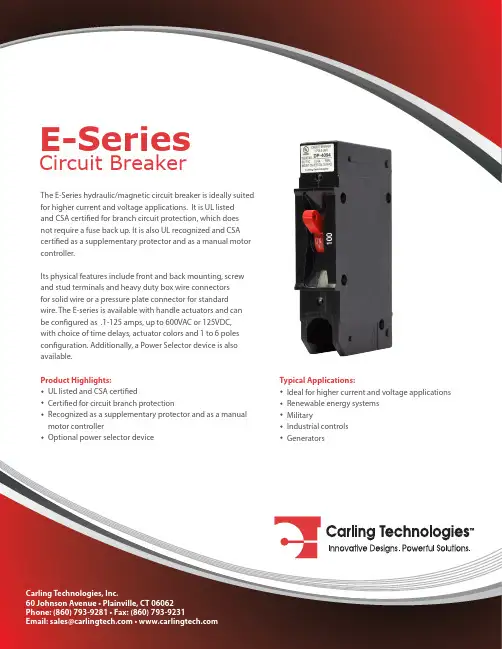
The E-Series hydraulic/magnetic circuit breaker is ideally suited not require a fuse back up. It is also UL recognized and CSA certified as a supplementary protector and as a manual motor Its physical features include front and back mounting, screw wire. The E-series is available with handle actuators and can*Manufacturer reserves the right to change product specification without prior notice.EnvironmentalPhysicalMechanicalElectricalDesigned in accordance with requirements of specificationMIL PRF-55629 & MIL-STD-202G as follows:Maximum Voltage 600VAC 50/60 Hz, 125VDC (SeeTable A)Current Ratings Standard current coils: 0.100, 0.250, 0.500, 1.00, 2.50, 5.00, 7.50, 10.0, 15.0, 20.0, 25.0, 30.0, 50.0, 60.0, 70.0 & 100 Amp.Auxiliary Switch Rating SPDT; 10.1A 250VAC, 1.0A 65VDC; 0.5A 80VDC, 0.1A 125VAC (with gold contacts). Insulation Resistance Minimum of 100 Megohms at 500 VDC.Dielectric Strength UL, CSA: 2200 V 50/60 Hz for one minute between all electrically isolated terminals. E-Series Circuit Breakers comply with the 8mm spacing and 3750V 50/60 Hz dielectric requirements from hazardous voltage to operator accessible surfaces, between adjacent poles and from main circuits to auxiliary circuits per Publications EN 60950 and VDE 0805.Resistance, Impedance Values from Line to Load Terminal - based on Series Trip Circuit Breaker.Endurance 10,000 ON-OFF operations @ 6 per minute; with rated Current and Voltage.Trip Free All E-Series Circuit Breakers will trip on overload, even when Handle is forcibly held in the ON position.Trip Indication The operating Handle moves positively to the OFF position when an overload causes the breaker to trip.Number of Poles 1 - 6Mounting A 3” minimum spacing must be provided between the circuitbreaker arc venting area on back connected E-Series circuit breakers and grounded obstructions. E-Series circuit breakers must be mounted on avertical surface.Connectors, Box Type Front connected E-Series circuit breakers are supplied with box type pressure connectors that accept copper or aluminum conductors as follows: 1/0-14Copper, 1/0-12 Aluminum.Internal Circuit Series and Switch Only, (with or Configuration without auxiliary switch). Shuntwith current coils.Weight Approximately 252 grams/pole(Approximately 9 ounces/pole)Standard Colors Housing-Black; Actuator - See Ordering Scheme.Shock Withstands 100 Gs, 6ms, sawtooth while carrying rated current per Method 213, Test Condition “I”. Vibration Withstands 0.060” excursion from 10-55 Hz, and 10 Gs 55-500 Hz, at rated current per Method 204C, Test Condition A. Moisture Resistance Method 106D, i.e., ten 24-hour cycles @ + 25°C to +65°C, 80-98% RH.Salt Spray Method 101, Condition A (90-95% RH @ 5% NaCl Solution, 96 hrs).Thermal Shock Method 107D, Condition A (Five cycles @ -55°C to +25°C to +85°C to +25°C).Operating Temperature -40° C to +85° CPulse Tolerance CurvesElectrical TablesTable A: Lists UL Listed (489) & CSA Certified (C22.2 No. 5) configurations & performance capabilities as a Molded Case Circuit Breaker.Table B: Lists UL Recognized & CSA Accepted configurations & performance capabilities as a Component SupplementaryAgency CertificationsUL Recognized UL Standard 1077UL Standard 1500UL ListedUL Standard 489CSA AcceptedCSA CertifiedTUV CertifiedVDE CertifiedComponent Recognition Program as Protectors, Supplementary (Guide QVNU2, File E75596)Component Recognition Program as Manual Motor Controls (Guide NLRV2, File E135367)Protectors, Supplementary for Marine Electrical & Fuel Systems (Guide PEQZ2, File E75596) Ignition ProtectionCircuit Breakers, Molded Case (Guide DIVQ, File E129899)Component Supplementary Protector (Class 3215 30, File 047848 0 000)CSA Standard C22.2 No. 235Circuit Breaker Molded Case (Class 1432 01, File 093910), CSA Standard C22.2 No. 5.1 - M EN60934 under License No. R72031056EN60934, VDE 0642 under File No. 10537Table C: Lists UL Recognized, CSA Accepted and VDE Certified configurations and performance capabilities as a Component Supplementary Protector.Table D: Lists UL Recognized, CSA Accepted configurations and performance capabilities as Protectors, Supplementary for Marine Electrical and Fuel Systems (Guide PEQZ2, File E75596). Ignition Protected per UL 1500. UL Classified Small Craft Electrical Devices, Marine in accordance with ISO 8846 (Guide UZMK, File MQ1515) as Marine Supplementary Protectors.Electrical TablesTable C Notes:1 Requires branch circuit backup with a UL LISTED Type K5 or RK5 fuse rated 15A minimum and no more than 4 times full load amp rating and not to exceed 225 amps.7 CURRENT RATING (AMPERES)7OR VOLTAGE COIL (MIN. TRIP RATING, VOLTS)5020 0.020025 0.025030 0.030035 0.035040 0.040045 0.045050 0.050055 0.055060 0.060065 0.065070 0.070075 0.075080 0.080085 0.085090 0.090090 0.095210 0.100215 0.150220 0.200225 0.250230 0.300235 0.350240 0.400245 0.450250 0.500255 0.550260 0.600265 0.650270 0.700275 0.750280 0.800285 0.850290 0.900295 0.950410 1.000512 1.250415 1.500517 1.750420 2.000522 2.250425 2.500527 2.750430 3.000435 3.500440 4.000445 4.500450 5.000455 5.500460 6.000465 6.500470 7.000475 7.500480 8.000485 8.500490 9.000495 9.500610 10.000710 10.500611 11.000711 11.500612 12.000712 12.500613 13.000614 14.000615 15.000616 16.000617 17.000618 18.000620 20.000622 22.000624 24.000625 25.000630 30.000635 35.000640 40.000650 50.000660 60.000670 70.000680 80.000690 90.000810 100.000811 110.000812 120.0009128 125.000CODE AMPERESA06 6 DC, 5 DC A12 12 DC, 10 DC A18 18 DC, 15 DC A24 24 DC, 20 DC A32 32 DC, 25 DC A48 48 DC, 40 DC A65 65 DC, 55 DC B25 125 DC, 100 DC J06 6 AC, 5 AC J12 12 AC, 10 AC J18 18 AC, 15 AC J24 24 AC, 20 ACJ48 48 AC, 40 AC J65 65 AC, 55 AC K20 120 AC, 65 AC L40 240 AC, 130 AC 1Series2Actuator3Poles6Frequency & Delay7Current Rating8Terminal12Agency Approval 4 Circuit5Auxiliary Switch E A B 01A22BC 244501 SERIES E2 ACTUATORAHandle, one per pole8 TERMINAL 12BACK CONNECTED (FRONT MOUNTED ONLY) MAX. RATING 19 10-32 Stud (All Terminals) 50 A 29 1/4-20 Stud (All Terminals) 120 A A 9 M5 Stud (Line & Load) 50 A B 9 M6 Stud (Line & Load) 100 A FRONT CONNECTED (BACK MOUNTED ONLY) MAX. RATING 310 Box Wire Connector (Line & Load) 100 A C 11 Box Wire Connector w/ Pressure Plate (Line & Load) 100 A 4 10-32 Screw (Line & Load) 50 A D M5 Screw (Line & Load) 50 A 5 10-32 “Bus-Type” Screw (Line), 10-32 Screw (Load) 50 A E M5 “Bus-Type” Screw (Line), 10-32 Screw (Load) 50 A 610 10-32 “Bus-Type” Screw (Line), Box Wire Connector (Load) 100 AF 1110-32 “Bus-Type” Screw (Line), Box Wire Connector w/ Pressure Plate (Load) 100 A 7 1/4-20 Screw (Line & Load) 100 A G M6 Screw (Line & Load) 100 A 8 1/4-20 “Bus-Type” Screw (Line), 1/4-20 Screw (Load) 100 A H M6 “Bus-Type” Screw (Line), M6 Screw (Load) 100 A 910 1/4-20 “Bus-Type” Screw (Line), Box Wire Connector (Load) 100 AJ 111/4-20 “Bus-Type” Screw (Line), Box Wire Connector w/ Pressure Plate (Load) 100 A10 MOUNTING/BARRIERSBACK CONNECTED (FRONT MOUNTED ONLY)Mounting Inserts A 6-32B ISO M3FRONT CONNECTED (BACK MOUNTED ONLY)14Back Mounting Foot Type Front Mounting Inserts (Optional Use)C Short 6-32 D Short ISO M3E Long 6-32 F Long ISO M33 POLES 11 One 2 Two 3 Three4 Four5 Five6 Six4 CIRCUIT 2A 3 Switch Only (no coil )B Series Trip (current )C Series Trip (voltage )DShunt Trip (current )E Shunt Trip (voltage )F Relay Trip (current )G Relay Trip (voltage )5 AUXILIARY SWITCH 40 without Auxiliary Switch2 S.P .D.T. 0.110 Q.C. Terminals3 S.P .D.T. 0.139 Solder Lug4 S.P .D.T. 0.110 Q.C. Terminals(Gold Contacts) 6 S.P .D.T. 0.110 Q.C. Terminals 7 S.P .D.T. 0.110 Q.C. Terminals (Gold Contacts)8 S.P .D.T. 0.187 Q.C. Terminals 9 S.P .D.T. 0.187 Q.C. Terminals6 FREQUENCY & DELAY033DC 50/60Hz, Switch Only 105 DC Instantaneous 12 DC Short 14 DC Medium 16 DC Long205 50/60Hz Instantaneous 22 50/60Hz Short 24 50/60Hz Medium 26 50/60Hz Long30 DC, 50/60Hz Instantaneous 32DC, 50/60Hz Short34 DC, 50/60Hz Medium 36 DC, 50/60Hz Long 62 50/60Hz Short, Hi-Inrush 64 50/60Hz Medium, Hi-Inrush 66 50/60Hz Long, Hi-Inrush 72 DC, Short,Hi-Inrush 74 DC,Medium, Hi-Inrush 76 DC, Long, Hi-Inrush926DC, 50/60Hz Short, Hi-Inrush 946DC, 50/60Hz Medium, Hi-Inrush966DC, 50/60Hz Long, Hi-Inrush 11 MAXIMUM APPLICATION RATING 1512 AGENCY APPROVALBDUL 1077 / UL508 Recognized & CSA Accepted UL 1077 Recognized, CSA Accepted, & VDE Certified 9Actuator Color10Mounting/Barriers11Maximum Application Rating9 ACTUATOR COLOR & LEGEND 13Actuator Color White Black Red Green Blue Yellow Gray Orange Legend Color Black White White White White Black Black BlackI-O A C F H K M P R ON-OFF B D G J L N Q S Dual12345678A 65 VDC, 120 A B 125 VDC, 120 A C 120/240 VAC, 100 A D 240 VAC, 100 A E 16 277/480 VAC, 100 A F 277 VAC, 100 A G 16 600 VAC, 100 A H 16 480 VAC, 100 A J 16 415 VAC, 100 A L 16 160 VDC, 100 A T 125 VDC/240 VAC, 100 A W 16 125 VDC/415 VAC, 100 A Notes:1 VDE approval on 1-5 poles only. Standard multi-pole units identical poles except when specifying auxiliary switch - (see Note 4). For mixed ratings, consult factory.2 Switch Only & Series Trip construction available w/either front or back connected terminals. Shunt construction available w/back connected terminals, (T erminal Codes 1 & 2) only. Circuit Codes B,C & D are VDE approved.3 Switch Only construction: 30 amps or less select Current Rating Code 630; 31-70 amps, select Current Rating code 670; 71-100 amps, select Current Rating Code 810; 101-125 amps Select Current Rating Code 912. Switch Only is VDE approved only if tied to a protected pole.4Auxiliary Switch available on Switch Only and Series Trip units. On multi-pole units, only one auxiliary switch is normally supplied mounted in the extreme right pole. Back mounted units require special mounting provisions when auxiliary switch is specified. VDE approval on Auxilary Switch Codes 0,2,3 & 4 only.5 Voltage Trip Coils are not rated for continuous duty. Available only with Frequency & Delay Codes 10 & 20. Series Trip construction with a voltage coil s VDE approved only if tied to a protected pole.6 Frequency & Delay Codes 92,94 & 96 are not VDE Certified.7 Current Coil Ratings 0.100 - 100 ams are VDE Certified.8 125 A rating (Code 912) available as a Switch Only (Circuit Code A), rated 125 VDC (Code B).9 An Anti-Flash Over Barrier is supplied between poles on multi-pole units with 10-32 (T erminal Code 1). 1/4-20 (Code 2), M5 (Code A), and M6 (Code B) terminals per UL requirement.10 Box Wire Connector will accept #14 through 0 AWG. copper wire or #12 through 0 AWG. aluminum wire.11 Box Wire Connector with Pressure Plate for stranded wire, consult factory for details.12 T erminal Codes A,B,D,E,G & H are not VDE Certified.13 VDE approvals require Dual (I-O, ON-OFF) or I-O markings on all handles.14 Back Mounted breakers can also be front mounted by utilizing the proper front panel mounting inserts normally supplied. However, terminal connections must be made prior to mounting.15 Application ratings B,D,J,T & W are available with VDE.16415, 480 & 600 VAC ratings require 3 or 4 pole break 3Ø and 2 pole break 1Ø.7 CURRENT RATING (AMPERES)7OR VOLTAGE COIL (MIN. TRIP RATING, VOLTS)5020 0.020025 0.025030 0.030035 0.035040 0.040045 0.045050 0.050055 0.055060 0.060065 0.065070 0.070075 0.075080 0.080085 0.085090 0.090090 0.095210 0.100215 0.150220 0.200225 0.250230 0.300235 0.350240 0.400245 0.450250 0.500255 0.550260 0.600265 0.650270 0.700275 0.750280 0.800285 0.850290 0.900295 0.950410 1.000512 1.250415 1.500517 1.750420 2.000522 2.250425 2.500527 2.750430 3.000435 3.500440 4.000445 4.500450 5.000455 5.500460 6.000465 6.500470 7.000475 7.500480 8.000485 8.500490 9.000495 9.500610 10.000710 10.500611 11.000711 11.500612 12.000712 12.500613 13.000614 14.000615 15.000616 16.000617 17.000618 18.000620 20.000622 22.000624 24.000625 25.000630 30.000635 35.000640 40.000650 50.000660 60.000670 70.000680 80.000690 90.000810 100.000811 110.000812 120.0009128 125.000CODE AMPERESA06 6 DC, 5 DC A12 12 DC, 10 DC A18 18 DC, 15 DC A24 24 DC, 20 DC A32 32 DC, 25 DC A48 48 DC, 40 DC A65 65 DC, 55 DC B25 125 DC, 100 DC J06 6 AC, 5 AC J12 12 AC, 10 AC J18 18 AC, 15 AC J24 24 AC, 20 ACJ48 48 AC, 40 AC J65 65 AC, 55 AC K20 120 AC, 65 AC L40 240 AC, 130 AC 1Series2Actuator3Poles6Frequency & Delay7Current Rating8Terminal12Agency Approval 4 Circuit5Auxiliary Switch E A B 01A22CC 244501 SERIES E2 ACTUATORAHandle, one per pole8 TERMINAL 7BACK CONNECTED (FRONT MOUNTED ONLY) MAX. RATING 18 10-32 Stud (All Terminals) 50 A 28 1/4-20 Stud (All Terminals) 125 A FRONT CONNECTED (BACK MOUNTED ONLY) MAX. RATING 39 Box Wire Connector (Line & Load) 100 A C 10 Box Wire Connector w/ Pressure Plate (Line & Load) 100 A 4 10-32 Screw (Line & Load) 50 A 5 10-32 “Bus-Type” Screw (Line), 10-32 Screw (Load) 50 A 69 10-32 “Bus-Type” Screw (Line), Box Wire Connector (Load) 100 AF 1010-32 “Bus-Type” Screw (Line), Box Wire Connector w/ Pressure Plate (Load) 100 A 7 1/4-20 Screw (Line & Load) 125 A 8 1/4-20 “Bus-Type” Screw (Line), 1/4-20 Screw (Load) 100 A 99 1/4-20 “Bus-Type” Screw (Line), Box Wire Connector (Load) 100 AJ 101/4-20 “Bus-Type” Screw (Line), Box Wire Connector w/ Pressure Plate (Load) 100 A10 MOUNTING/BARRIERSBACK CONNECTED (FRONT MOUNTED ONLY)Mounting Inserts A 6-32B ISO M3FRONT CONNECTED (BACK MOUNTED ONLY)11Back Mounting Foot Type Front Mounting Inserts (Optional Use)C Short 6-32 D Short ISO M3E Long 6-32 F Long ISO M33 POLES 11 One 2 Two 3 Three4 Four5 Five6 Six4 CIRCUIT 2BSeries Trip (current )C 3 Series Trip (voltage )5 AUXILIARY SWITCH 40 without Auxiliary Switch2 S.P .D.T. 0.110 Q.C. Terminals3 S.P .D.T. 0.139 Solder Lug4 S.P .D.T. 0.110 Q.C. Terminals(Gold Contacts) 6 S.P .D.T. 0.110 Q.C. Terminals 7 S.P .D.T. 0.110 Q.C. Terminals (Gold Contacts)8 S.P .D.T. 0.187 Q.C. Terminals 9 S.P .D.T. 0.187 Q.C. Terminals6 FREQUENCY & DELAY105 DC Instantaneous 12 DC Short 14 DC Medium 16 DC Long205 50/60Hz Instantaneous 22 50/60Hz Short 24 50/60Hz Medium 26 50/60Hz Long30 DC, 50/60Hz Instantaneous 32 DC, 50/60Hz Short 34DC, 50/60Hz Medium36 DC, 50/60Hz Long 62 50/60Hz Short, Hi-Inrush 64 50/60Hz Medium, Hi-Inrush 66 50/60Hz Long, Hi-Inrush 72 DC, Short,Hi-Inrush 74 DC,Medium, Hi-Inrush 76 DC, Long, Hi-Inrush926DC, 50/60Hz Short, Hi-Inrush 946DC, 50/60Hz Medium, Hi-Inrush966DC, 50/60Hz Long, Hi-Inrush 11 MAXIMUM APPLICATION RATING 12 AGENCY APPROVALCFUL 489 Listed & CSA Certified UL 489 Listed, CSA Certified, & VDE Certified 9Actuator Color10Mounting/Barriers11Maximum Application Rating9 ACTUATOR COLOR & LEGEND 12Actuator Color White Black Red Green Blue Yellow Gray Orange Legend ColorBlack White White White White Black Black BlackON-OFF B D G J L N Q S Dual 123456781 120 VACB 125 VDC, 120 AC 13 120/240 VAC, 100 AD 240 VAC, 100 ANotes:1 Standard multi-pole units identical poles except when specifying auxiliary switch - (see Note 4). For mixed ratings, consult factory. VDE Certification on 1-5 poles only.2 Series Trip construction available w/either front or back connected terminals.3 Series Trip construction with a voltage coil is not available as a single pole unit and must be tied to a protected pole.4 On multi-pole units, only one auxiliary switch is normally supplied mounted in the extreme right pole per Figure A. Back mounted units require special mounting provisions when auxiliary switch is specified. VDE Certification on auxilary switch codes 0, 2, 3 & 4 only.5 Voltage Trip Coils are not rated for continuous duty. Available only with Frequency & Delay Codes 10 & 20.6 Frequency & Delay Codes 92, 94 & 96 are not VDE Certified.7 Current Ratings under 0.100 amps are not VDE Certified .8 An Anti-Flash Over Barrier is supplied between poles on multi-pole units with 10-32 Stud (T erminal Code 1) or 1/4-20 Stud (Code 2) terminals per UL requirement.9 Box Wire Connector will accept #14 through 0 AWG. copper wire or #12 through 0 AWG. aluminum wire.10 Box Wire Connector with Pressure Plate for stranded wire, consult factory for details.11 Back Mounted breakers can also be front mounted by utilizing the proper front panel mouning inserts normally supplied. However, terminal connections must be made prior to mounting.12 VDE Certification requires dual (I-O , ON-OFF) markings on all handles.13 Not available with VDE Certification.Notes:1 All dimensions are in inches [millimeters].2 T olerance ±.020 [.51] unless otherwise specified.3 0-50 amps: 10-32 & M5 Studs .625±.062/15.88±1.574 long.4 51-120 amps: 1/4-20 & M6 Studs .750±.062/19.05±1.574 long.Notes:1 1/4 -20 stud terminal in Series Trip circuit configuration shown.2 A 3” min spacing must be provided between the circuit breaker arc venting areaof back connected E-Series circuit breaker and grounded obstructions.3 All dimensions are in inches [millimeters].4 T olerance ±.020 [.51] unless otherwise specified.5 Circuit breakers must be mounted on vertical surface.Notes:1 All dimensions are in inches [millimeters].2 T olerance ±.020 [.51] unless otherwise specified.3 Box wire connector terminal in Series Trip circuit configuration shown.4 Circuit breakers must be mounted on vertical surface.REV_CB_E_01_2014。
高压断路器中的弹簧操动机构刘唯2015.4摘要:本文讨论了断路器操动机构的功能,总结并比对了目前主流弹簧操动机构的实现方式,也介绍了各种结构的优缺点。
列举了断路器上弹簧机构的各种布局方式,从控制,安全,维护及发展的角度谈了个人看法。
关键词: 高压断路器弹簧操动机构目录0引言 (1)1操动机构的种类 (1)2弹簧操动机构的功能 (2)3断路器弹簧操动机构结构 (3)3.1储能结构的分类 (4)3.1.1储能操作的能量只用于合闸过程43.1.2储能操作的能量分别用于合闸或分闸过程4 3.2储能到位离合及状态保持结构 (5)3.3合闸驱动结构 (5)3.3.1不具备自由脱扣的结构63.3.2具备自由脱扣功能的结构6 3.4合闸状态保持结构 (6)3.4.1过冲复位保持结构63.4.2复位保持结构73.4.3就绪保持结构7 3.5储能电机的减速机构 (7)3.5.1齿轮箱结构73.5.2蜗轮蜗杆结构73.5.3棘轮结构7 3.6弹簧机构的联锁装置 (8)3.6.1硬联锁83.6.2软联锁83.6.3PF接点9 4断路器弹簧操动机构的布局 (9)5断路器的控制与保护 (10)6断路器操动机构的安全锁 (11)7断路器弹簧操动机构的维护 (11)8断路器弹簧操动机构的发展 (5)0引言笔者最近几年,接触了一些弹簧操动机构,有些认识,愿与大家分享。
文中没有计算,没有公式,略显没有深度,请高手一笑而过。
文中试图将千差万别的机械结构进行分类,会有遗漏,但终归是一次尝试。
也试图将其优缺点做一比较,必不完全,但肯定会有些说法。
有些机构,并不能完全理解其博大精深,不正之处,也还望请指正。
请到新浪微博《高压断路器中的弹簧操动机构》交流贴留言。
链接如下:/u/2437510622。
原文下载请搜百度文库。
文中涉及到一些机构名称,如ABB公司的EL弹簧操动机构,以下简称EL机构,主要用于VD4断路器;Schneider公司的P2弹簧操动机构,以下简称P2机构,主要用于Evolis断路器和Masterpact断路器;Schneider公司的RI弹簧操动机构,以下简称RI机构,主要用于Ev12S断路器上;Schneider公司的RT弹簧操动机构,以下简称RT机构,主要用于Premset 开关柜上;Schneider公司的FK2-01弹簧操动机构,以下简称FK2机构,主要用于HVX断路器上;三菱的BH2弹簧操动机构,以下简称BH2机构,主要用于VPR 断路器上;天水长城开关厂的GSL01弹簧操动机构,以下简称GSL01机构,主要用于EVH1断路器;以下断路器上用的弹簧操动机构不知道名字,只能用断路器名字称呼,VS1断路器上的弹簧操动机构,以下简称VS1机构;厦门华电开关有限公司的VEP断路器上的机构,以下简称VEP机构;Siemens公司的Sion断路器上采用的机构,以下简称Sion机构;东芝公司的VK断路器上采用的机构,以下简称VK机构。
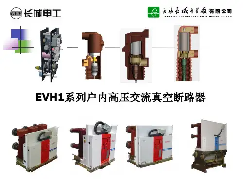
E-VAC EP Series Medium Voltage Vacuum Circuit BreakerAutomotiveAerospaceTruckHydraulicsAutomotive Aerospace Truck Hydraulics Poweringbusiness worldwideEaton delivers the power inside hundreds of products that are answering the demands of today’s fast changing world. We help our customers worldwide manage the power they need for buildings, aircraft, trucks, cars, machinery and entire businesses. And we do it in a way that consumes fewer resources.Next generationtransportationEaton is driving the development of newtechnologies – from hybriddrivetrains and emission control systems to advanced engine components – that reduce fuel consumption and emissions in trucks and cars. Higher expectationsWe continue to expand our aerospace solutions andservices to meet the needs of new aviation platforms,including the high-flying light jet and very light jet markets. Building on our strengths Our hydraulics businesscombines localised service and support with an innovative portfolio of fluid powersolutions to answer the needs of global infrastructure projects, including locks, canals and dams.Powering Greener Buildings and BusinessesEaton’s Electrical Group is a leading provider of powerquality, distribution and control solutions that increase energy efficiency and improve power quality, safety and reliability. Our solutions offer a growing portfolio of “green” products and services, such as energy audits and real-time energy consumption monitoring.Eaton’s Uninterruptible Power Supplies (UPS), variable-speed drives and lighting controls help conserve energy and increase efficiency.ElectricalElectrical E-VAC EP Series Medium Voltage Vacuum Circuit Breaker 1Eaton Corporation is a worldwide leader in thedesign, manufacture, and sale of safe, reliableand high-performance medium voltage power distribution equipment in accordance with IEC,GB and ANSI standards.Complete Global Medium Voltage Switchgear Solutions Eaton, a premier leader in designing and manufacturing power distribution and protection equipment in the electrical industry, offers a comprehensive range of medium voltage (MV) solutionsto meet the needs of virtually every application. From productsthat feature cutting-edge design that allow for easy access, maintenance and space savings, to arc-resistant products that enhance safety, Eaton’s medium voltage solutions provide avariety of products for every need. Additionally, Eaton’s global service network provides maximum customer support in allregions of the world.As one of the few completely vertically integrated and diversified industrial manufacturers in the world, Eaton designs not only MV assemblies, but also the key components that comprise the MV solutions – from steel housing and circuit breaker compartmentsto vacuum interrupters, circuit breakers, bus systems and fuses. Eaton’s MV heritage, strengthened by acquisitions such as Westinghouse DCBU, Cutler Hammer, MEM and Holec, has resulted in breakthrough MV technologies and numerous international patents over the years.Part of Eaton’s complete electrical PowerChain Solutions– which help businesses minimize risks while realizing greater reliability, cost efficiencies, capital utilization and safety –Eaton’s medium voltage equipment meets all applicablestandards and certifications such as IEC, NEMA / ANSI, GB,UL, IEEE, KEMA and CSA.When it comes to medium voltage solutions, you can trust theone name with a long history of proven performance: Eaton.E-VAC EP Series Medium Voltage VacuE-VAC EP Series Medium Voltage Vacuum Circuit BreakerE-VAC EP Series medium voltage Ideal contact material and E-VAC EP Vacuum Circuit Breakervacuum circuit breakers from geometry ensure low Eaton Electrical combine our chopping current andexcellent vacuum technology reliable contact resistance . with decades of experience in designing and manufacturing A few components and power distribution system. They compact and reasonable offer high reliability, ease of structure ensure morehandling and maintenance, high reliable and safer operation. cost efficiency for Chinese users. Enable ideal cutoff and close Meet GB and DL standards. of resistance, inductance load and capacitive load. E-VAC equipped with new generation vacuum Secondary plug, chassis,interrupter, suited formoving contact and grounding technologies and operation methods are speciallycondition of power system. designed to Chinese users, completely compatible with E-VAC utilizes solid-enveloped domestically dominantpole of Eaton Electrical, offers medium voltage switchgear superior and reliable solid KYN28.enveloping insulation performance, passescondensation test, suitable for safely operating in harsh environment. It offers better creepage distance and clearance compared to the requirements in GB standards.Product modelsE -VAC -12 / T □ -□GB StandardEaton breaker seriesVoltage ratings kVRated current ARated short circuit breakingcurrent kASpring operation mechanismE-VAC EP Series Medium Voltage Vacuum Circuit Breaker3Application condition Technical features Temperature condition Ambient air temperature not E-VAC utilizes mature spring Product assembly utilizes The average of relative exceeding 40℃, and the operating mechanism, offers tooling method to ensure humidity measured within 24 average value measured within reliable and stable dimension consistency. All hours not exceeding 95%.24 hours not exceeding 35℃. performance, long service life, products have been subject toThe minimum ambient air ease of operating, excellent the push panel test for The average vapor pressure temperature is -15℃.corrosion protection and low standard panel, ensuring measured within 24 hours notmaintenance within the lifetime product interchangeability and exceeding 2.2kPa.The effect by solar radiation universality.can be ignored. E-VAC EP series 12kV vacuum The average of relativecircuit breaker adopts mature All products have been subject humidity measured within one The ambient air is not obviously APG process to enclose to hundreds of mechanical month not exceeding 90%.polluted by dust, smoke, vacuum interrupter and main operation running-in testscorrosive or flammable gases, conductive circuit in a before leaving the factory, The average vapor pressure vapor or salt mist. insulation tube, thoroughly ensuring the product measured within one montheliminating the environmental performance in the most stable not exceeding 1.8kPa.Seismic intensity not impact on insulated parts phase.exceeding 8 degree. which weakens the voltagewithstanding capacity, ensuring Utilize advanced importedAmplitude of electromagnetic the vacuum interrupter suitable testing equipment, exactlyinterference induced in for harsh environment. record no-load mechanicalsecondary system not characteristics of each product,exceeding 1.6kV. E2 level electrical life extended and provide users with theseand M2 level mechanical life characteristic curves, ensureextended as per GB1984-2003, product reliability.capacitive current breaking andlowre-breakdown probability C2level, having completed thetype test.Outline dimension anddistribution panel interlockingmethod completely compatiblewith domestically dominantmedium voltage switchgearKYN28, high universality,significantly reduce design cost4E-VAC EP Series Medium Voltage Vacuum Circuit BreakerE-VAC EP Series Medium Voltage Vacuum Circuit BreakerApplication areasChemical industry Substation Oil industry Cement industry Piping industry Automotive industry Offshore mining Power plantShipbuildingTextile and food industries Paper making industry Metallurgical industryOpencast coal mineT echnology creation historyAs the manufacturer of the world’s first vacuum interrupter, the pioneer of vacuum technology, Eaton Electrical has been committed to the research, development andmanufacturing of vacuum interrupters for over 70 years, and gathered plenty of experience. Westinghouse has become the synonym of quality and reliability.We own the world’s largest and globally leading vacuum interrupter plant and the only vacuum interrupter plant that is equipped with large capacity high voltage laboratories.Our manufacturing capacity and design and development always maintain a leadership position.E-VAC vacuum circuit breaker requires almost no relevant maintenanceSimple structure design of E-VAC vacuum circuit breaker further minimizes fault occurrence, simplifies daily maintenance. With the indicator on the circuit breaker panel, no detection instrument isrequired, facilitating the judgment of working state of circuit breaker. The circuit breaker utilizes the world’s first class Eaton Electrical’s vacuum interrupter with vacuum degree up to 10-6Pa, low air leakage, and ensure 50-year life with no maintenance required.Optional accessoriesCharging handle Trolley handle LifterIdeal for control and protection in medium voltage power supply and distribution systemThe circuit breaker is equipped with superior spring chargingmechanism, utilizes modular design, offering optimized mechanism main part distribution, simpler structure and more reliable performance. The whole mechanism is composed by three modules: charging,closing, opening. Assembly and maintenance of these three parts are very simple. The spring charging mechanism composed by ratchet wheel mechanism, oscillator and closing spring is compact and smart. The operating mechanism is usually equipped with manual charging device and electric charging device, enabling automatic reclosing function.The circuit for manual charging operating mechanism is provided with manual opening and closing operation buttons, circuit breaker position indicator and spring mechanism charging status indicator, switch operations counter, shunt release auxiliary switch, position and fault signals, etc..The circuit breaker of electric charging operating mechanism: added with spring charging motor, shunt release, trip free relay, and auxiliary switch for spring charging motor release.The following accessories can also be provided as needed: undervoltage release, overcurrent relay, etc..E-VAC EP Series Medium Voltage Vacuum Circuit Breaker5E-VAC EP Series Medium Voltage Vacuum Circuit BreakerMain specification and technical parametersItem Unit ValueRated voltage kV 12Rated short-time power frequency withstand voltage (1 min) 42 (phase to ground, phase to phase) 48 (gap)Rated lightning impulse withstand voltage (peak) 75 (phase to ground, phase to phase) 85 (gap)Rated frequency Hz 50Rated current A 630 630 1250 1250 1600 1250 16001250 1600 2000 2000 2500 2000 250040002500 2500 3150 3150 (1)4000 3150 (1) Rated short-circuit breaking current kA 25 31.5 40 50Rated short-time withstand current (4s) 25 31.5 40 50125Rated peak withstand current kA 63 80 100 (2)125Rated short circuit making current 63 80 100 (2) Secondary circuit power frequency withstand voltage (1 min) V 2000Opening time ms 20~50Closing time 35~70Mechanical endurance time 30000 (1600A/31.5kA and below), 20000 (2000A and above, 40kA), 10000(50kA) Rated current breaking endurance 30000 (1600A/31.5kA and below), 20000 (2000A and above, 40kA), 10000(50kA) Rated short circuit current breaking endurance time 50 (1600A/31.5kA and below), 30 (2000A and above, 40~50kA)Allowable accumulated wearingthickness of moving/fixed contact mm 3Rated closing operating voltage V AC 110/220 DC 110/220Rated opening operating voltageRated voltage of spring charging motor V AC 110/220 DC 110/220Rated power of spring charging motor W 55~90Charging duration s ≤15Rated operating sequence O-0.3s-CO-180s-CO (40kA and below), O-180s-CO-180s-CO (50kA)Note:(1) Forced air cooling is required at 4000A; (2) For higher parameters, please contact the Eaton Corp.T echnical parameters for trip/close coilsName ParameterRated operating voltage (V) AC, DC110 AC, DC220Rated operating current of close coil (A) 2.0 1.0Rated operating current of trip coil (A) 1.8 (40kA and above is 2.6) 0.9 (40kA and above is 1.6)Normal operating voltage range Closing: 80%~110% of rated operating voltageOpening: 65%~120% of rated operating voltage, opening will not occur when thenormal operating voltage is less than 30% of rated operating voltageE-VAC EP Series Medium Voltage Vacuum Circuit Breaker 6E-VAC EP Series Medium Voltage Vacuum Circuit BreakerOutline and dimension of E-VAC EP circuit breaker (drawout type)Distribution Rated Rated short panelcurrent circuit breaking width (mm) (A) current (kA)P H A B C D E G J K L M N R S T W Q 800 630 25~31.5 210 275 638 652 640 650 433 Φ35 280 598 76 78 637 508 277 40 23 / 800 1250 25~40 210 275 638 652 640 650 433 Φ49 280 598 76 78 637 508 277 40 23 550* 800 1600 31.5 210 275 638 652 640 650 433 Φ55 280 598 76 78 637 508 277 40 23 / 800 2000 40 210 310 638 652 640 650 361 Φ79 295 586 77 88 698 536 277 0 23 550 800 1250~2000 50 210 310 638 652 640 650 361Φ79295 586 77 88 698 536 277 0 19 550 1000 2500 31.5 275 310 838 852 838 850 361 Φ109 295 586 77 88 698 536 377 0 31 / 1000 3150 31.5 275 310 838 852 838 850 361 Φ109 295 586 77 88 725 536 377 0 31 / 10002500~400040~50275310 838 852838 850361 Φ109295586 77 88 725 53637731750**Note:Forced air cooling is required at 4000A. * 40kA only. ** 50kA only.E-VAC EP Series Medium Voltage Vacuum Circuit Breaker7E-VAC EP Series Medium Voltage Vacuum Circuit BreakerOutline and dimension of E-VAC EP circuit breaker (fixed type)E-VAC fixed type vacuum circuit breaker (210 phase space)Rated Rated shortcurrent circuit breaking(A) current (kA) H J E K B N Y1\Y2630~125025~31.527523771.54370555I 12504027523771.54370551II160031.5~4027523771.54370551II 200040310252804493614III1250~200050310252804493614IIIE-VAC EP Series Medium Voltage Vacuum Circuit Breaker 8E-VAC EP Series Medium Voltage Vacuum Circuit BreakerOutline and dimension of E-VAC EP circuit breaker (fixed type)E-VAC fixed type vacuum circuit breaker (275 phase space)Rated Rated short current circuit breaking (A) current (kA)M Z1\Z2 2500 31.5 628 IV 3150 31.5 678 V 2500~400040~50678VE-VAC EP Series Medium Voltage Vacuum Circuit Breaker9E-VAC EP Series Medium Voltage Vacuum Circuit BreakerSecondary control connection diagram of E-VAC EP series vacuum circuit breaker (drawout type) The diagram shows the circuit breaker in test position, opening, discharged statesE-VAC EP Series Medium Voltage Vacuum Circuit Breaker 10E-VAC EP Series Medium Voltage Vacuum Circuit BreakerSecondary control connection diagram of E-VAC EP series vacuum circuit breaker (fixed type) The diagram shows the circuit breaker in opening, discharged states11E-VAC EP Series Medium Voltage Vacuum Circuit BreakerE-VAC EP Series Medium Voltage Vacuum Circuit BreakerE-VAC EP series vacuum circuit breaker selection table1. Circuit breaker models□E-VAC (drawout type)□ E-VAC (fixe d type)2. Parameters of E-VAC EP series vacuum circuit breaker Panel width (mm) Breaker phase Rated short circuit Rated working current (A)spacing(mm) breaking current (kA) □630 □1250 80021025 □630□1250□ 160031.5 □1250 □ 1600 □ 2000 40 □1250 □ 1600□ 2000 501000 275 25 □2500 31.5 □2000□ 2500□ 315040 □1250 □ 1600 □ 2000 □ 2500 □ 3150 □ 4000* □□□ □□□1250 1600 2000 2500 31504000*50* Forced air cooling is required at 4000A.* * The specifications such as the need to purchase, please contact Eaton. 3. Technical parameters of spring operating mechanism Opening power supply (V) □DC110 □ AC110 □ DC220 □ AC220 Closing power supply (V)□DC110 □ AC110 □ DC220 □AC220 Spring charging motor power supply (V)□DC110 □ AC110 □ DC220 □AC2204. Optional configuration (standard option includes trip free device. Please note if the trip free device has to been canceled)□ Overcurrent release □ 2 Overcurrent □ 3 Overcurrent□A□ Closing latch □ V □ Position latch □ V□ Trip free relay □ V □ Undervoltage release □V□ Operating handle□ Quantity neededNote: Technical parameters of products will be changed without notice. Please confirm withEaton corporation before ordering.E-VAC EP Series Medium Voltage Vacuum Circuit Breaker 12•Electrical solutions that use less energy, improve power reliability andmake the places we live and work safer and more comfortable•Hydraulic and electrical solutions that enable machines to delivermore productivity without wasting powerWe deliver:Discover today’s Eaton.•Aerospace solutions that make aircraft lighter, safer and less costly tooperate, and help airports operate more effciently•Vehicle drivetrain and powertrain solutions that deliver morepower to cars, trucks and buses, while reducing fuel consumption and emissionsPowering business worldwideAs a global diversif ed power management company, We provide integrated solutions that help make we help customers worldwide manage the power energy, in all its forms, more practical and accessible. needed for buildings, aircraft, trucks, cars, machinery and businesses.With 2014 sales of $22.6 billion, Eaton has approxi-mately 99,000 employees around the world and sells Eaton’s innovative technologies help customers manage products in more than 175 countries.electrical, hydraulic and mechanical power more reliably, eff ciently, safely and sustainably.Eaton is a power management company with approximately 97,000 employees. The company provides energy-efficient solutions that help our customers effectively manage electrical, hydraulic and mechanical power more efficiently, safely and sustainably. Eaton sells products to customers in more than 175 countries. For more information, visit . Electrical Sector Asia PacificNo. 3 280 Nong Linhong RoadChangning DistrictShanghai, China 200335© 2016 Eaton Corporation Eaton is a registered trademarkAll Rights Reserved of Eaton Corporation.Printed in ChinaE-VAC EP-EN All trademarks are property of theirMay 2016 respective owners.。
智能型万能式断路器使用说明书1.概述1.1适用范围HJW1系列空气断路器(以卜简称断路器)主要适用于交流50Hz,额定工作电压为400V、690V,额定电流为400A-6300A的配电网络中,用来分配电能和保护线路及电源设备免受过载、欠电压、短路取和接地等故障的危害。
断路器核心部件采用智能型控制器,具有精确的选择性保护,可避免不必要的停电,提高供电系统的可靠性、连续性和安全性。
1.2型导及其舍义1 3正常的使用,安装和运输条件1.3.1正常使用条件a)周围空气温度上限不超U+40℃,下限不低于-5℃,24h的平均值不超过+35℃,注:在周围空气温度高于+40℃或低-5℃的条件下使用的断路器应与制造厂协商。
b)安装地点的海拔不超过2000m,c)大气的相对湿度在周围最高温度+40℃时不超过50%,在较低在温度下可以有较高的相对湿度(侧如20℃时的90%),并考虑到因温度变化发生在产品表面上的凝露。
1.3.2正常安装条件a)安装位置应垂直、各方向的倾斜度不超过5℃;b)污染等缎:3级c)安装类别:断路器主电路及欠电压脱扣器线圈、电源变压器初级线圈为Ⅳ级,辅助电路、控制电路为Ⅲ级。
1 3 3正常贮存和运输条件a)温度下限不低于-25℃,上限小超过十55℃,b)相对湿度(25℃时)不超过95%,c)产品在运输过程中,应轻搬轻放,小应倒放,应尽量避免剧烈碰撞。
2.技术特征21分类2.1.1按安装方式分:固定式、抽屉式。
2 1 2按操作方式分:电动操作、手动操作。
2 1 3按脱扣器种类:具有智能型控制器、欠电压瞬时(或延时)脱扣器和分励脱扣器。
2 1 4智能型控制器分娄:a) Perfection-L(简称L)型(经济型,光柱显示),h) Perfection-M(简称M)型(普通型,LED数码显示),c) Perfection-H (简称H)型(增强型,LCD液晶显示)。
2.2主要技术参数见表1表1主要技术参数2 .3主要技术性能2.3. l智能型控制器保护特性的电流整定值范围及准确度见表2。
ContentsDescription Page Table 1. Revision notes (2)Table 2. Breaker catalog number convention ...............................................3Table 3. Symmetrical RMS interruption ratings (kA) for 1-pole breaker frame ......................4Table 4. Symmetrical RMS interruption ratings (kA) for 2-, 3-, and 4-pole breaker frames ............4Table 5. Curve notes ..................................................................4Thermal magnetic trip unit curvesFigure 1. Fixed thermal fixed magnetic single pole 15 A-125 A. .................................5Figure 2. Fixed thermal fixed magnetic two, three, and four pole 15 A-125 A......................6Figure 3. Fixed thermal fixed magnetic DC. ................................................7Figure 4. 240 V peak let through current. .................................................8Figure 5. 240 V peak let through energy...................................................9Figure 6. 480 V peak let through current. .................................................10Figure 7. 480 V peak let through energy. ..................................................11Figure 8. 600 V peak let through current. .................................................12Figure 9. 600 V peak let through energy.. (13)T ime current curves Power Defense MCCB Frame 1 thermal-magnetic2Technical Data TD012063ENEffective November 2019Time current curves Power Defense MCCBFrame 1 thermal-magneticEATON T able 1. Revision notes.ote: NUnless noted below, all curves remain unchanged from their prior revision.3Technical Data TD012063ENEffective November 2019Time current curves Power Defense MCCB Frame 1 thermal-magnetic EATON This information is provided only as an aid to understand the catalog numbers.It is not to be used to build catalog numbers for circuit breakers or trip units as all combinations may not be available.T able 2. Breaker catalog number convention.ote: N IEC standard breakers include the CE mark; GB standard breakersinclude the CCC mark.Poles1 = 1 pole2 = 2 pole3 = 3 pole4 = 4 pole with 100% neutral protection 0 = 4 pole with 0% neutral protectionInterrupting ratingdesignator kA at 480 V (UL)C = 18F = 25G = 35K = 50M = 65N = 85P = 100Continous currentrating0015 = 15 A 0020 = 20 A 0025 = 25 A 0030 = 30 A 0035 = 35 A 0040 = 40 A 0045 = 45 A 0050 = 50 A 0060 = 60 A 0070 = 70 A 0080 = 80 A 0090 = 90 A 0100 = 100 A 0110 = 110 A 0125 = 125 ATerminals includedN = No terminalsJ = Line and load terminals K = Line only terminals L = Load only terminalsTrip unit typeTFF = Fixed thermal / fixed magnetic (non UL)VFF = 50ºC fixed thermal / fixed magnetic (non UL)KNS = Molded case switchBreaker familyPDG1 = Frame 1 Global UL / CSA / IEC / GBPDG1 3 M 0125 TFF J4Technical Data TD012063ENEffective November 2019Time current curves Power Defense MCCBFrame 1 thermal-magneticEATON T able 3. Symmetrical RMS interruption ratings (kA) for 1-pole breaker frame.T able 4. Symmetrical RMS interruption ratings (kA) for 2-, 3-, and 4-pole breaker frames.** Note: 250 Vdc is achieved using 2 poles in series.T able 5. Curve notes.1.These curves apply for 50 Hz and 60 Hz applications.2.The maximum voltage rating for the frame style is stated in Tables 3 & 4.3.These curves are comprehensive for Power Defense style circuit breakers including frame sizes, ratings and constructions stated.4.The total clearing times shown include the response time for the trip unit, the breaker opening and the interruption of the current. The bottom of the time band is the minimum commit to trip time.5.The end of the instantaneous curve is determined by the application or the interrupting rating of the circuit breaker.6.Thermal magnetic trip unit calibration based on 40ºC ambient, cold start. Tested with 4 feet of rated wire (75ºC) per terminal. Tested in open air with current in all poles.7Thermal magnetic trip unit instantaneous calibration based on single pole testing.Technical Data TD012063ENEffective November 2019Time current curves Power Defense MCCB Frame 1 thermal-magnetic CurvesTime current curvesTechnical Data TD012063EN Effective November 2019Time current curves Power Defense MCCBFrame 1 thermal-magneticEATON Time current curves67Technical Data TD012063ENEffective November 2019Time current curves Power Defense MCCB Frame 1 thermal-magnetic EATON Time current curves8Technical Data TD012063ENEffective November 2019Time current curves Power Defense MCCBFrame 1 thermal-magneticEATON Figure 4. 240 V peak let through current. October 20199Technical Data TD012063ENEffective November 2019Time current curves Power Defense MCCB Frame 1 thermal-magnetic EATON Figure 5. 240 V peak let through energy.October 201910Technical Data TD012063ENEffective November 2019Time current curves Power Defense MCCBFrame 1 thermal-magneticEATON 11EATON 12Effective November 2019EATON Figure 9. 600 V peak let through energy. October 201913EATON Eaton1000 Eaton Boulevard Cleveland, OH 44122United States877-ETN-CARE (877-386-2273) © 2019 EatonAll Rights ReservedPrinted in USAPublication No. TD012063EN / TBG001429 November 2019Eaton is a registered trademark.All other trademarks are property of their respective owners.Effective November 2019。
3B SCIENTIFIC ® PHYSICS1Fuente de alta tensión E (230 V, 50/60 Hz) 1013412 Fuente de alta tensión E (115 V, 50/60 Hz) 1017725Instrucciones de uso12/13 SD/ALF1 Ajuste de la alta tensión2 Indicación de la tensión3 Salida de la tensión decaldeo 4 Casquillo de puesta atierra5 Salida de la alta tensión6 Pie soporte abatible7 Interruptor de la red8 Fusibles9 Conmutador de tensión 10 Ventilador1. Aviso de seguridadLa fuente de alta tensión E corresponde a las regulaciones de seguridad para dispositivos eléctricos de medición, de mando, de control y de laboratorio, estipuladas por la norma DIN EN 61010, parte 1, y ha sido montada según la clase de protección I. Está prevista para el servicio en recintos secos, convenientes para los medios de servicio eléctricos.Su uso correcto, acorde con las prescripciones, garantiza el servicio seguro del equipo. Sin embargo, la seguridad no queda garantizada si el dispositivo se usa incorrectamente o se lo manipula sin el cuidado necesario.Si es de suponer que ya no es posible un funcionamiento libre de peligro (por ejemplo, por daños visibles), se debe poner el equipo fuera de servicio inmediatamente.En escuelas e instalaciones educativas, el funcionamiento del equipo debe ser supervisado responsablemente por personal instruido al respecto.•Antes de la primera puesta en marcha, se debe comprobar si el valor impreso en el la-do posterior de la caja corresponde a las exigencias locales de tensión.•Antes de poner en marcha el aparato se debe examinar si existen daños en la caja oen la conexión a la red y, en caso de fallosen el funcionamiento o daños visibles, se debe poner el equipo fuera de servicio ase-gurándolo contra una puesta en marcha in-voluntaria.•El aparato se conecta sólo en enchufes con un conductor de protección conectado a latierra.•Antes de la conexión, revisar si las conexio-nes de experimentación se encuentran libres de daños en el aislamiento o si los cables están pelados.•Los fusibles defectuosos sólo se deben sustituir con uno correspondiente al valor original (ver lado posterior de la caja).•Es necesario desenchufar el aparato antes de cambiar el fusible.•Nunca se debe cortocircuitar el fusible o el portafusibles.•Dejar siempre libres las ranuras de venti-lación de la caja, con el fin de garantizar una suficiente circulación de aire, necesariapara el enfriamiento de los componentes in-ternos.•Sólo un electrotécnico está autorizado a abrir el aparato.2. DescripciónLa fuente de alimentación de alta tensión de Ees una fuente de uso universal, ajustable y librede tierra, para el trabajo con tubos de electrones.Ésta entrega una alta tensión, regulada, ajustable sin saltos, no peligrosa al contacto,con limitación pasiva de corriente. Un trasformador incorporado resistente a altatensión sirve para la toma de la tensión decaldeo para tubos de electrones. Un ventilador termorregulado protege contra el sobrecalentamiento.La fuente de alimentación de tensión 1017725está dimensionada para una tensión de red de115 V (±10 %) resp. 1013412 para 230 V (±10%).3. Datos técnicosTensión de conexióna la red: 115 / 230 V CA ± 10%,ver dorso de la carcasa Frecuencia de la red: 50 / 60 HzProtección por fusible: 115 V: 2x 1 A lento,230 V: 2x 0,5 A lentoAlta tensión: 0 - 5000 V CC, max. 2mATensión decaldeo: 6,3 V CA, max. 3 A,resistente hasta 6 kVProtección de sobrecarga: Primario: fusible, verdorso de la carcasaSecundario: resistenciasde limitación de corriente Contactos: casquillosdeseguridadde 4-mmIndicación: digitalExactitud de indicación: 1% + 2 DigitsTemperatura del medio: de 5 °C hasta 40 °CHumedad relativa max. 80 %Dimensiones: aprox. 240x220x90 mm3Peso: aprox. 2,1 kg4. Servicio4.1 Notas generales•Antes de conectar la fuente de alimentación,el ajuste de alta tensión se lleva a 0(extremo izquierdo).•Se interconecta el montaje experimental conla fuente de alimentación.23B Scientific GmbH ▪ Rudorffweg 8 ▪ 21031 Hamburgo ▪ Alemania ▪ Se reservan las modificaciones técnicas © Copyright 2013 3B Scientific GmbH• Se conecta la fuente de alimentación sólocuando el montaje experimental ya esté listo. • Cambios el montaje experimental se debenrealizar sólo con el circuito sin corriente. • Con el ajuste de alta tensión se fija ahora la tensión deseada.•Antes de la desconexión de la fuente de alta tensión el ajuste de alta tensión se debe haber retornado a 0 (extremo izquierdo).4.2 Reemplazo de fusibles •Desconecte la alimentación de corriente. Esimprescindible que también desconecte el enchufe de la red.• Se saca el portafusible en la parte traserade la fuente, utilizando un destornillador plano (ver Fig. 1) • Se fija el destornillador del lado del enchufepara aparato frio. • Se remplaza el fusible y se vuelve a insertar el portafuibles.Fig. 1 Reemplazo de fusibles5. Mantenimiento, limpieza, desecho • El aparato debe permanecer en un lugarlimpio, seco y libre de polvo. • Antes de la limpieza el aparato se separadel suministro de corriente. • No se debe usar ningún elemento agresivoni disolventes para limpiar el aparato. • Para limpiarlo se utiliza un trapo suavehúmedo. • El embalaje se desecha en los lugareslocales para reciclaje. •En caso de que el propio aparato se deba desechar como chatarra, no se debe deponer entre los desechos domésticos normales. Se deben cumplir las prescripciones locales para el desecho de chatarra eléctrica.6. Ejemplo de aplicaciónFuncionamiento del tubo de difracción de electronesSe requiere adicionalmente:1 Tubo de difragción de electrones D1013885 1 Soporte de tubos D1008507 Observación: Se puede poner al potencial de tierra, ya sea el ánodo o el cátodo, porque la salida de tensión de caldeo es resistente a la alta tensión.Fig. 2 Funcionamiento del tubo de difracción de electrones。