ASTM E155-2010 铝和镁铸件检验用标准参考射线照片
- 格式:pdf
- 大小:107.46 KB
- 文档页数:4
厚度2英寸[51mm]以下的铸钢件标准参考射线底片1 适用范围1.1 这些参考射线底片列举了在厚度2英寸[51mm]以下的铸钢件上产生的各种缺陷的种类和等级(注1)。
注1:在E71中曾提到过这种厚度的参考射线底片,但E71中只包含了一种现在不常用的γ源——镭。
当前的文档中包括了一些已认可的缩孔或C级,,取消了裂纹类和热裂缝类, 除这两类缺陷的一张底片外。
更厚的参考射线底片可以在E186和E280中找到。
1.2 这些参考底片包括以下独立的三套(注2):(1)中压(标称250-kVp)X射线。
(2)1-MV X射线和铱-192(Ir-192)射线。
(3)2-MV到 4-MV X射线和钴-60(Co-60)射线。
每套比较的只是同一种射线产生的底片。
应该注意的是每个能量级不适用于本文中的所有厚度。
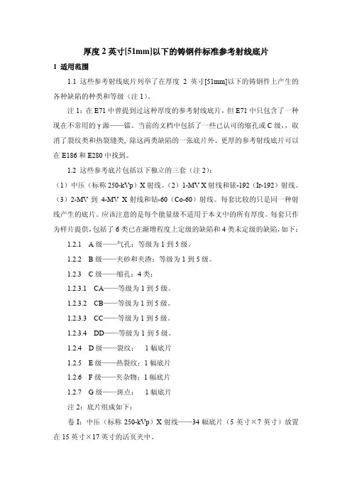
每套只作为样片提供,包括了6类已在渐增程度上定级的缺陷和4类未定级的缺陷,如下: 1.2.1 A级——气孔;等级为1到5级。
1.2.2 B级——夹砂和夹渣;等级为1到5级。
1.2.3 C级——缩孔;4类:1.2.3.1 CA——等级为1到5级。
1.2.3.2 CB——等级为1到5级。
1.2.3.3 CC——等级为1到5级。
1.2.3.4 DD——等级为1到5级。
1.2.4 D级——裂纹;1幅底片1.2.5 E级——热裂纹;1幅底片1.2.6 F级——夹杂物;1幅底片1.2.7 G级——斑点;1幅底片注2:底片组成如下:卷Ι:中压(标称250-kVp)X射线——34幅底片(5英寸×7英寸)放置在15英寸×17英寸的活页夹中。
卷II:1-MV X射线和Ir-192射线——34幅底片(5英寸×7英寸)放置在15英寸×17英寸的活页夹中。
卷III:2-MV到 4-MV X射线和Co-60射线——34幅底片(5英寸×7英寸)放置在15英寸×17英寸的活页夹中。
注3:虽然在三卷中都列出了G级——斑点,但斑点的出现取决于射线能量等级。
注:1、气孔属于圆形缺陷(圆形是指长宽比小于或等于3)2、单个的气孔在要求较高的情况下,单个气孔缺陷长径>T/3(T母材厚度)的为不合格;单个的气孔在要求一般的情况下,单个气孔缺陷长径>T/2(T母材厚度)的为不合格。
3、对于成组的气孔缺陷,在单一评定去你按表2和表1评定缺陷点数并定级,对于同一产品多个评定区的缺陷的综合评定,根据具体情况进行评定(推荐是综合评定等级是,某一评定区最高评定等级加1级)4、对于同一评定区内的多个缺陷的综合评定,根据具体情况进行评定(推荐是综合评定等级是,某一评定区最高评定等级加2级)5、对缺陷的综合评定还一定要考虑到缺陷的黑度或缺陷与母材的对比度,来确定缺陷对产品的危害程度进行评定其缺陷等级。
注:1、条孔或条渣属于条形缺陷(圆形是指长宽比大于3)2、单个的条孔或条渣在要求较高的情况下,单个条孔或条渣缺陷长径>T/3(T母材厚度)的为不合格;单个的条孔或条渣在要求一般的情况下,单个条孔或条渣缺陷长径>T/2(T母材厚度)的为不合格。
3、对于成组的条孔或条渣缺陷,对与同一产品多个评定区的缺陷的综合评定,根据具体情况进行评定(推荐是综合评定等级是,某一评定区最高评定等级加1级)。
4、对于同一评定区内的多个缺陷的综合评定,根据具体情况进行评定(推荐是综合评定等级是,某一评定区最高评定等级加2级)。
5、对缺陷的综合评定还一定要考虑到缺陷的黑度或缺陷与母材的对比度,来确定缺陷对产品的危害程度进行评定其缺陷等级。
度)的为不合格;单个的低密度夹渣在要求一般的情况下,单个低密度夹渣缺陷长径>T/2(T母材厚度)的为不合格。
2、对于成组的低密度夹渣缺陷,对与同一产品多个评定区的缺陷的综合评定,根据具体情况进行评定(推荐是综合评定等级是,某一评定区最高评定等级加1级)。
3、对于成组的低密度夹渣缺陷,在单一评定去你按表2和表1评定缺陷点数并定级,对于同一产品多个评定区的缺陷的综合评定,根据具体情况进行评定(推荐是综合评定等级是,某一评定区最高评定等级加1级)4、对于同一评定区内的多个缺陷的综合评定,根据具体情况进行评定(推荐是综合评定等级是,某一评定区最高评定等级加2级)。
ASME标准射线底片评定规则UW-51焊接接头射线照相及射线显示检验(A89)b)焊缝的射线照相显示出下列的缺陷特征可判定为不合格。
……。
⑴.任何显示特征为裂纹或未熔合或未焊透区域。
⑵.任何其它条型显示其长度大于:a.T<3/4in(19mm)1/4in(6.4mm)b.T≥3/4in(19mm)1/3 Tc.T≥9/4in(57mm)3/4in(19mm)其中:T=除去允许的焊缝余高后的焊缝厚度,对两不等厚零件的对接焊缝,T等于两者中的较薄者,若全焊透焊缝包含角焊缝,则该角焊缝的腰高应计入T内。
⑶.任何在一直线上的显示,在12T的长度内累计长度大于T者,但相领缺陷间是间距超过6L者除外,这里L为该群显示内最长缺陷的长度。
⑷.圆形显示超过附录4中合格标准所规定者。
附录4用射线照相法测定焊缝中圆形显示的圆形显示图的验收标准。
4-3验收标准(a)图象黑度显示中的图象黑度可以不同,它不作为验收或拒收的标准。
(b)需考虑的显示(见表4-1)只有超过下列尺寸的圆形显示才予以考虑。
T≤3.2mm时为1/10TT =3.2mm至6.4mm时为0.397mm;6.4mm<T≤50.8mm时为0.79mm;T >50.8mm时为1.6mm。
(c)圆形显示的最大尺寸(见表4-1)任何显示的最大许可尺寸应为1/4T或3.97mm中的较小者,但与相邻显示相距25.4mm或更远的单个显示例外,它可以等于1/3T或6.4mm中的较小者。
对T大于50.8mm,单个显示的最大许可尺寸应增加到9.5mm。
(d)线性排列圆形显示在长度等于12T内显示各直径的总和小于T时,线性排列圆形显示是合格的。
见图4-1。
各组线性排列圆形显示的长度及各组显示之间的间距应符合图4-2的要求。
P462P1171表4-1厚度Tin小于1/81/83/161/45/163/87/169/165/811/163/4~2超过2mm小于3.23.24.86.47.99.511.112.714.315.917.519.1~50.8超过50.8圆形显示的最大许可尺寸mm 不规则的1/4T1.1941.6001.9812.3112.7693.1753.6073.9623.9623.9623.962单个的1/3T1.0671.6002.1082.6423.1753.7084.2674.7755.8426.359.5250.7871.600注:此表仅作为例子。
86E CNAS L0690检验报告TEST REPORT中心编号(NO):006委托单位:雅泰实业集团有限公司样品名称:铝塑板检验类别:委托检验国家建筑材料测试中心National Rescarch Center Of Testing Techniques For Building Materials国家建筑材料测试中心(National Rescarch Center Of Testing Techniques For Building Materials)检验报告(Test Report)中心编号: 006 第1页,共3页批准:审核:编制:检验单位地址:北京市朝阳区管庄中国建材院南楼电话:邮编:100024国家建筑材料测试中心(National Rescarch Center Of Testing Techniques For Building Materials)检验报告(Test Report)中心编号(NO): 006 第2页,共3页序号检验项目标准要求检验结果单项结论1铝材厚度平均值≥标称值最小值≥标称值面铝平均值最小值背铝平均值最小值2涂层厚度平均值≥16um最小值≥14um 平均值25um最小值24um合格3涂层光泽度偏差≤10偏差光泽度合格4表面铅笔硬度≥HB2H合格5涂层柔韧性≤3T2T合格6涂层附着力划格法0级划圈法1级划格法0级划圈法1级合格7耐冲击性≥不脱漆,无裂痕不脱漆,无裂痕合格8耐热水性无变化无变化符合9涂层耐沾污性≤5%%合格10涂层耐酸性无变化无变化符合11涂层耐碱性无变化无变化符合12涂层耐油性无变化无变化符合13涂层耐溶剂性不露底不露底符合检验单位地址:北京市朝阳区管庄中国建材院南楼电话:邮编:100024国家建筑材料测试中心(National Rescarch Center Of Testing Techniques For Building Materials)检验报告(Test Report)中心编号(NO): 006 第3页,共3页序号检验项目标准要求检验结果单项结论14弯曲强度≥标称值正面纵向88MPa——正面横向83MPa背面纵向92MPa背面横向85MPa15剥离强度平均值≥mm最小值≥mm 正面纵向平均值mm最小值mm合格正面横向平均值mm最小值mm背面纵向平均值mm最小值mm背面横向平均值mm最小值mm16热变形温度≥85℃98℃合格17耐温差性剥离强度下降率≤10%5%合格涂层附着力划格法0级划圈法1级划格法0级划圈法1级合格外观无变化无变化合格备注:(此处空白)检验单位地址:北京市朝阳区管庄中国建材院南楼电话:邮编:100024。
铝铸件和镁铸件检测用标准参照射线照片本标准以固定的名称E 155发布;紧跟名称后的数字表示最初采用的年份或在进行了修订的情况下的最近修订的年份。
圆括号中的数字表示最近批准的年份。
上标易普西龙(ε)表示在最近修订或重新批准时进行了编辑更改。
这些参照射线照片由质量控制委员会和宇航工业联合会的宇航研究和试验协会合作开发的。
本标准已被批准在国防部机构使用。
1. 范围1.1 这些参照射线照片图解说明了可能在铝合金和镁合金铸件中发现的缺陷的类型和程度。
图解的铸件厚度为1.4英寸(6.35 mm)和3.4英寸(19.1 mm)。
1.2 在没有其它可以应用文件时,对其它材料厚度,如果已经证明可以应用时和在采购商和制造商之间已达成协议的场合,可以使用本文件。
1.3 用英寸-磅单位标明的数值应视为标准数值。
1.4 本标准的主旨不是来阐述所有的安全相关点,如果有,只是与其使用相关联。
建立合适的安全和健康规则并在使用前确定规则条款的适用性,这些是本标准的使用者的责任。
注1 -卷I:该套参照射线照片包含13片覆盖了铝合金铸件中的缺陷的照片和10片覆盖了镁合金铸件中的缺陷的照片。
每片照片都是用8.5英寸宽11英寸长(216 mm宽279 mm长)的纸板框架框着,并且每片照片图解说明在约2英寸宽2英寸长(51 mm宽51 mm长)的面积内的缺陷的8个严重级别。
这些纸框含在10.5英寸宽11.5英寸长(267 mm宽292 mm长)的套具内。
卷II:该套参照射线照片仅包含4片覆盖了镁合金铸件中的缺陷的照片。
每片照片都是用8.5英寸宽11英寸长(216 mm宽279 mm长)的纸板框架框着,并且每片照片图解说明缺陷的8个严重级别(除了离散缺陷以外,这里对每种缺陷只给出了一个例子)。
注2 -参照射线照片E 505包含了适用于厚度在1英寸(25 mm)以下的铝压铸件和镁铸件的参照射线照片。
2. 引用文件2.1 ASTM标准:E 94 射线探伤指导E 142 射线探伤质量控制方法E 505 铝压铸件和镁压铸件检测用参照射线照片E 1316 无损探伤术语2.2 ASTM附件:铝铸件和镁铸件检测用标准参照射线照片:卷I,铝铸件和镁铸件卷II,镁铸件3. 术语3.1 定义-本标准使用的定义可能会在术语E 1316中找到。

铸件外观标准附示意图铝、锌合金铸件外观检查标准1.范围及基本责任1.1 应用于对铸件产品外观检查。
1.2 质量部负责人和生产部负责人负责推行及维持。
2.外观表面质量的定级2.1 质量的定级按使用范围分为三级,见下表:表面质量使用范围备注相应使用之AQL水平1 级喷涂工艺要求高的表面;需镀铬.抛光.研磨的表面;相对运动的配合面;危险应力区的表面一般相当于(▽6)⊕Ⅱ1.0% (个别0.65%)2 级喷涂要求一般或要求密一般相当于(▽5)ΘⅡ2.5%封的表面;需镀锌.阳极氧化的表面;喷涂前不补涂的表面;装配接触面;3 级具保护性(例如防锈)的喷涂表面;紧固接触面;喷涂前可允许补涂的表面;其它要求低的表面;一般相当于(▽4)ΟⅡ4.0%3.压铸件外观检查项目3.1 成型不良a)项目代号:A1b)定义:成型过程中填充不完整的部位这是因为以下原因所造成的:-----料不足-----料温低-----模温低-----压力不足,压入速度太慢c)检查:目视d)要求:1级和2级:不允许3级:如不影响装配及使用则允许3.2 冷格a)项目代号:A2b)定义:温度较低的金属流互相对接但未熔合而出现的缝隙,呈不规则的线形,有穿透.不穿透的两种,在外力作用下有发展的趋势。
c)检查:目视d)要求:1级:不允许2级:在每一个表面允许2处,其长度不大于铸件最大轮廓尺寸的1/10,深度不大于壁厚的1/5,离铸件边缘距离不小于4mm,并且两冷格间距不小于10mm。
3级:在每一个表面允许2处,其长度不大于铸件最大轮廓尺寸的1/5,深度不大于壁厚的1/4,离铸件边缘距离不小于4mm,并且两冷格间距不小于10mm。
3.3 流纹a)项目代号:A3b)定义:表面上用手感觉得出的局部下陷的纹路。
此缺陷无发展的可能,用抛光法能去除。
c)检查:目视d)要求:1级:允许流纹面积不超过总面积的5%,其深度不大于0.05mm。
2级:允许流纹面积不超过总面积的15%,其深度不大于0.07mm。
铸钢件放射照片评定标准(参考)这个标准被发表在固定名称E446;紧跟在名称后的数字表明最初采用的年,或版本,最终版的年。
圆括号中的数表明最后重新批准的年。
一个上角标的希腊字母表明社论从最后版本或重新批准起改变。
该标准被国防部批准使用。
1.范围1.1这些参考放射照片2说明在断面厚度达到2英寸(51mm)钢铸件中存在的各种类型和间断程度。
(注 1)注 1-先前用于这个厚度的参考放射照片是列于E 71标准中,但包括现在很少使用的γ源,即,镭。
当前文件被更新,包含几种类型的收缩或类别C间断,并取消了这些裂缝和热撕裂的分类,仅分别保留了一个示例。
更厚的部分的参考放射照片可以在E 186和E 280中查找。
1.2这些参考实例包括独立的三套(注 2)如下:(1)中压(额定250-kVp)X射线。
(2)1-MVX射线和铱-192辐射,和(3)2-MV至4-MV X射线和钴-60辐射。
每套只能用于与相等的辐射的产品的放射照片比较。
应当确认,每种能量水平不能适用于文件所包含的全部的厚度范围。
每套包括6类按严重程度的递增分级的间断和4类不分级的间断,仅提供了一些示例。
如下:1.2.1A类-气孔;严重程度1到5。
1.2.2B类-夹砂和夹渣;严重程度1到5。
1.2.3C类-收缩;4种:1.2.3.1CA-严重程度1到5。
1.2.3.2CB-严重程度1到5。
1.2.3.3CC-严重程度1到5。
1.2.3.4CD-严重程度1到5。
1.2.4D类-裂缝;1实例。
1.2.5E类-热撕裂;1实例。
1.2.6F类-嵌入物;1实例。
1.2.7G类-斑点;1实例。
注 2-实例如下:卷Ⅰ中压(额定250-kVp)X射线参考放射照片-一套34张照片(5*7英寸)装订成15*17英寸的活页图册。
卷Ⅱ 1-MV X射线和铱-192参考放射照片-一套34张照片(5*7英寸)装订成15*17英寸的活页图册。
卷Ⅲ 2-MV至4-MV X射线和钴-60参考放射照片-一套34张照片(5*7英寸)装订成15*17英寸的活页图册。
ASTM铸钢件放射照片评定标准(参考)铸钢件放射照片评定标准(参考)这个标准被发表在固定名称E446;紧跟在名称后的数字表明最初采用的年,或版本,最终版的年。
圆括号中的数表明最后重新批准的年。
一个上角标的希腊字母表明社论从最后版本或重新批准起改变。
该标准被国防部批准使用。
1.范围1.1这些参考放射照片2说明在断面厚度达到2英寸(51mm)钢铸件中存在的各种类型和间断程度。
(注 1)注1-先前用于这个厚度的参考放射照片是列于E 71标准中,但包括现在很少使用的γ源,即,镭。
当前文件被更新,包含几种类型的收缩或类别C间断,并取消了这些裂缝和热撕裂的分类,仅分别保留了一个示例。
更厚的部分的参考放射照片可以在E 186和E 280中查找。
1.2这些参考实例包括独立的三套(注2)如下:(1)中压(额定250-kVp)X射线。
(2)1-MVX射线和铱-192辐射,和(3)2-MV至4-MV X射线和钴-60辐射。
每套只能用于与相等的辐射的产品的放射照片比较。
应当确认,每种能量水平不能适用于文件所包含的全部的厚度范围。
每套包括6类按严重程度的递增分级的间断和4类不分级的间断,仅提供了一些示例。
如下:1.2.1A类-气孔;严重程度1到5。
1.2.2B类-夹砂和夹渣;严重程度1到5。
1.2.3C类-收缩;4种:1.2.3.1CA-严重程度1到5。
1.2.3.2CB-严重程度1到5。
1.2.3.3CC-严重程度1到5。
1.2.3.4CD-严重程度1到5。
1.2.4D类-裂缝;1实例。
1.2.5E类-热撕裂;1实例。
1.2.6F类-嵌入物;1实例。
1.2.7G类-斑点;1实例。
注 2-实例如下:卷Ⅰ中压(额定250-kVp)X射线参考放射照片-一套34张照片(5*7英寸)装订成15*17英寸的活页图册。
卷Ⅱ 1-MV X射线和铱-192参考放射照片-一套34张照片(5*7英寸)装订成15*17英寸的活页图册。
卷Ⅲ 2-MV至4-MV X射线和钴-60参考放射照片-一套34张照片(5*7英寸)装订成15*17英寸的活页图册。
hb6578铝镁合金铸件检验用标准参考射线底片HB6578铝镁合金铸件的检验用标准参考射线底片包括以下几个方面:
1. 几何尺寸和形状:通过观察射线底片上的测量尺寸和形状来检验铸件的几何尺寸是否符合要求。
2. 缺陷:铝镁合金铸件可能存在气孔、夹杂、裂纹等缺陷,在射线底片上可以清晰地观察到这些缺陷,并进行定量测量和评估。
3. 变形:铸造过程中可能会出现铸件变形的情况,射线底片可以检测出其中的变形程度和方向。
4. 焊接接头:对于铝镁合金铸件的焊接接头,射线底片可以检测焊缝是否完整、无裂纹等情况。
5. 内部结构:铝镁合金铸件的内部结构也可以通过射线底片来观察,评估铸件的合理性和质量情况。
综上所述,射线底片是HB6578铝镁合金铸件检验中不可或缺的工具和标准参考。
E155(第一卷)铝镁铸件射线参考底片图谱第一卷铝镁铸件由ASTM E07委员会发布(无损探伤)本批图谱是在航空工业委员会下属质量控制委员会及航空测试研究委员会指导合作下开发完成。
a (P1) ALUMINUM--GAS HOLES –1/4in铝-气孔-1/4英寸b(P8) ALUMINUM--GAS HOLES –3/4in铝-气孔-3/4英寸c(P7) ALUMINUM--GAS POROSITY (ROUND) –1/4in铝-气孔(圆形)-1/4英寸d(P13) ALUMINUM--GAS POROSITY (ROUND) –3/4in铝-气孔(圆形)-3/4英寸e(P6) ALUMINUM--GAS POROSITY (ELONGATED) –1/4in铝-气孔(小长气泡)-1/4英寸f(P12) ALUMINUM--GAS POROSITY (ELONGATED) –3/4in铝-气孔(小长气泡)-3/4英寸g(P4) ALUMINUM--SHRINKAGE--CA VITY--1/4in铝-缩孔-1/4英寸h(P5) ALUMINUM--SHRINKAGE--(SPONGE)--1/4in铝-缩孔(海绵)-1/4英寸i(P11) ALUMINUM--SHRINKAGE--(SPONGE)--3/4in铝-缩孔(海绵)-3/4英寸j(P3) ALUMINUM--FOREIGN MATERIAL (LESS DENSE)--1/4in 铝-外部材料-(较小密度)-1/4英寸k(P10) ALUMINUM--FOREIGN MATERIAL (LESS DENSE)--3/4in 铝-外部材料-(较小密度)-3/4英寸I(P2) ALUMINUM--FOREIGN MATERIAL (MORE DENSE)--1/4in 铝-外部材料-(较大密度)-1/4英寸m(P9) ALUMINUM--FOREIGN MATERIAL (MORE DENSE)--3/4in 铝-外部材料-(较大密度)-3/4英寸n(P14) MAGNESIUM—GAS HOLES—1/4in镁-气孔-1/4英寸o(P19) MAGNESIUM—GAS HOLES—3/4in镁-气孔-3/4英寸p(P17) MAGNESIUM—MICROSHRINKAGE (FEATHERY)—1/4in 镁-微缩孔(羽毛状)-1/4英寸q(P22) MAGNESIUM—MICROSHRINKAGE (FEATHERY)—3/4in 镁-微缩孔(羽毛状)-3/4英寸r(P18) MAGNESIUM—MICROSHRINKAGE (SPONGE)—1/4in镁-缩孔(海绵状)-1/4英寸s(P23) MAGNESIUM—MICROSHRINKAGE (SPONGE)—3/4in镁-缩孔(海绵状)-3/4英寸t(P16) MAGNESIUM—FOREIGN MATERIAL (LESS DENSE)—1/4in 镁-外部材料(较小密度)-1/4英寸u(P21) MAGNESIUM—FOREIGN MATERIAL (LESS DENSE)—3/4in 镁-外部材料(较小密度)-3/4英寸v(P15) MAGNESIUM—FOREIGN MATERIAL (MORE DENSE)—1/4in 镁-外部材料(较大密度)-1/4英寸w(P20) MAGNESIUM—FOREIGN MATERIAL (MORE DENSE)—3/4in 镁-外部材料(较大密度)-3/4英寸E155(第二卷)铝镁铸件射线参考底片图谱第二卷镁铸件由ASTM E07委员会发布(无损探伤)本批图谱是在航空工业委员会下属质量控制委员会及航空测试研究委员会指导合作下开发完成。
铝镁合金压铸件X-ray探伤检测对比参考胶片标准范围1.1 这些参考照片把在铝镁合金在压铸生产中产生地内部缺陷按类型和等级进行了分类和说明,它能提供如下功能:1.1.1通过射线检查对铸件内部缺陷地类型和等级进行评定地指南1.1.2提供了零件接收标准、协议、图纸中地内部缺陷地说明和术语1.1.3英制单位如英寸-磅被作为标准中地所注明地单位注意:1).此套参考胶片包含5张8-1/2到11英寸地胶片,胶片中包含铝镁合金压铸件中地射线检测照片,前4张包含2组每组4个按严重等级递增地射线照片,最后一张包含两个未定级地射线照片2).此套参考照片也适用于臂厚一直达到2英寸地铝合金和镁合金地铸件1.2 有两种按下面所说地分类说明1.2.1评级-在铝合金和镁合金中有3种内部缺陷,每种缺陷按严重等级分为4个等级,A类缺陷阐述1/8英寸和5/8英寸壁厚地铝合金和镁合金压铸件,B类缺陷阐述1/8英寸地铝合金和镁合金压铸件,C类缺陷阐述1/8英寸地铝合金和镁合金压铸件1.2.2未分级-一幅照片阐述了0.2英寸地铝合金压铸件,一幅照片阐述了1/8英寸地镁合金压铸件1.3此标准在供方和需方达成协议地情况下也可用于其他材料、壁厚地零件1.4本标准未能注重所有关乎安全使用条件,假如需要,标准地使用者应该进行安全和健康地实验以确定在使用前进行限制2.参考文献2.1 ASTM标准E94 射线探伤检查指导E155 铝合金和镁合金铸件探伤参考照片E1316 无损检测术语2.2ASTM 相关文件铝合金和镁合金射线参考照片3.术语3.1定义——见E 13164.X射线照片说明4.1下面地说明针对缺陷地确认和分级,只对参考地X射线照片有效4.1.1 A类(气孔)——圆形或椭圆形,边缘光滑总体灰暗,常见单独或成片集结4.1.2 B类(冷隔)——明显发暗地边缘,长度不等,光滑地外边,通常连续或交叉存在4.1.3 C类(缩孔)——多呈不规则形状连续或交叉存在4.1.4 D类(夹杂)——在照片中呈孤立地不规则形状,比周围区域或明或暗,它表示了氧化物或杂质及金属化合物地可能5.意义和使用5.1这些照片用来如有特殊要求时地零件地接收准则,照片都是有内部缺陷零件地X射线照片,适用零件地壁厚范围见表15.2表1说明了分4个严重等级地3种缺陷和2个未分级地夹杂缺陷5.3这些参考照片是从E 94复制而来,所有地参考照片都是原始地X射线探伤照片5.4照片损坏——照片在使用中容易损坏,所以应小心使用,长期使用图象质量也会下降,所以应定期检查有无破损和脏污,影响判定地照片应及时更换.6.适用基础6.1参考照片用来作为零件地接收标准,标准应用于目地使用地零件上且遵守如下原则6.1.1未特殊注明下,在标定地单位面积上小于或等于特殊地参考等级缺陷是可接受地,在接受协议中单位面积地尺寸应注明.比参考照片严重地等级应报废6.1.2参考照片也可以用于组合地情况下,可以注明每种缺陷地种类,或者在零件地不同部分定不同地级别6.1.3在零件地同一部分如有多种类型缺陷应注意,任何零件接收准则地更改都应基于在不同地缺陷都已经有清楚规定地情况下6.1.4在X射线照片中如有多个缺陷情况下,如气孔等,接受准则应基于缺陷地总面积,最大地缺陷尺寸,孔间距或这些地综合来验收评定6.1.5 作为最小地接受准则应该包括下列信息:零件地可接受地每种类型缺陷地等级和需要射线检测部分区域7.关键词7.1 铝;压铸件;缺陷;镁;参考X射线照片;X射线。
2012191324Z CNAS L1401(2012)(粤)质监验字019号检验报告Test Report样品名称:铝质穿孔金属吊顶-方板委托单位:佛山市南海联兴得利装饰材料有限公司检验类别:委托检验佛山市质量计量监督检测中心Foshan Supervision Testing Center of Quality Metrology佛山市质量计量监督检测中心检验报告表号:QR-052-01第1页,共4页产品名称、型号、规格、商标、等级铝质穿孔金属吊顶-方板300*1200mm600*1200mm生产日期2013年11月05日编号或批号————样品单号0001793任务来源广东省佛山市质量技术监督局检验类别定期监督检验受检单位佛山市南海联兴得利装饰材料有限公司抽样数量2㎡受检单位地址佛山市南海区罗村联和工业区石谒朗西留样数量1㎡生产单位佛山市南海联兴得利装饰材料有限公司抽样基数500㎡生产单位地址佛山市南海区罗村联和工业区石谒朗西抽样日期2013年12月07日抽样单位佛山市质量计量监督检测中心抽样人张翔刘忠华抽样地点成品仓样品数量及状态完好检验依据GB/T 23444-2009《金属及金属复合材料吊顶板》DQ C-084-2013《佛山市建筑用其他金属制品产品质量定期监督检验细则》检验结论经检验,所检验项目符合GB/T 23444-2009《金属及金属复合材料吊顶板》标准的要求,依据《佛山市建筑用其他金属制品产品质量定期监督检验细则》的判定原则,本次定期监督检验合格。
检验报告专用章签发日期:2013年12月18日备注1、委托检验,送样。
2、主要仪器设备:电子天平(LP2102);3、代表数量1500㎡。
批准:审核:主检:佛山市质量计量监督检测中心检验报告。
ASTM E155铝镁铸件检验用标准参考射线底片图谱使用和定量ASTM E155是什么?1.本参考射线底片用于说明可能在铝合金铸件和镁合金铸件中存在缺陷的类型和程度。
图谱中所示的铸件厚度为1.4英寸(约6.35mm)和3.4英寸(约19.1mm)。
参考底片仅作为本文件中的辅助文件,需单独从ASTM购买。
2.参考底片不适用于数字成像时在铝合金铸件和镁合金铸件中出现的不连续类型和严重程度。
(注:铝合金铸件数字成像时参考ASTM E2422,镁合金铸件数字成像时参考ASTM E2869)3.对于其它材料厚度,在没其他的适用文件存在时,采购商和制造商之间达成协议,则可使用本文件。
4.X射线底片在制作的过程中可能有轻微的变化,变化可能包括底片或者使用化学药品处理的变化、模具或印刷或纸板的变化。
但无需过分担心底片图谱的品质,图谱监制小组都参考了原版的固定模型进行整理满足验收要求。
5.以英寸作为标准单位,括号内为转换单位。
6本标准的主旨不是用来阐述所有的安全相关点,如果用,只是与其使用相关联。
建立合适的安全和健康规则并在使用前确定规则的适用性,这些是本标准使用者需要承担的责任。
共两卷卷,信息如下:卷1:该套射线照片包含了13张覆盖了铝合金铸件中的缺陷中的照片和10张覆盖了镁合金铸件的缺陷中的照片。
每张照片都固定于85英寸宽11英寸长(216imm宽279mm长)的纸板框架中,并且每张照片图解说明在约2英寸宽2英寸长(51lmmm宽51mm长),面积内的缺陷的8个严重级别。
这些纸框含在10.5英寸宽11.5英寸长的套具内。
卷2:该套射线参考底片包含4张覆盖了镁合金铸件中缺陷的照片,每张照片都置于8.5英寸宽11.5英寸长(216mm宽279mm长)的纸板框架中,且每张照片的图解说明缺陷的8个严重级别(除了离散缺陷以外,这里对每种缺陷只给出了以一种例子)。
参考射线照片E505包含了适用厚度在1英寸(25mm)以下的铝压铸件和铁铸件的参考射线照片。
Designation:E155−10Standard Reference Radiographs forInspection of Aluminum and Magnesium Castings1This standard is issued under thefixed designation E155;the number immediately following the designation indicates the year of original adoption or,in the case of revision,the year of last revision.A number in parentheses indicates the year of last reapproval.A superscript epsilon(´)indicates an editorial change since the last revision or reapproval.These Reference Radiographs have been developed in cooperation with the Quality Control Committee and Aerospace Research and Testing Committee of the Aerospace Industries Association.This standard has been approved for use by agencies of the Department of Defense.1.Scope1.1These reference radiographs illustrate the types and degrees of discontinuities that may be found in aluminum-alloy and magnesium-alloy castings.The castings illustrated are in thicknesses of1⁄4in.(6.35mm)and3⁄4in.(19.1mm).The reference radiographfilms are an adjunct to this document and must be purchased separately from ASTM International if needed.1.2Thesefilm reference radiographs are not intended to illustrate the types and degrees of discontinuities found in aluminum-alloy castings when performing digital radiography. If performing digital radiography of aluminum-alloy castings, refer to Digital Reference Image Standard E2422.Magnesium-alloy digital reference images are not currently available from ASTM International.1.3This document may be used where no other applicable document exists,for other material thicknesses for which it has been found to be applicable and for which agreement has been reached between the purchaser and the manufacturer.1.4The values stated in inch-pound units are to be regarded as the standard.The values given in parentheses are mathemati-cal conversions to SI units that are provided for information only and are not considered standard.1.5This standard does not purport to address all of the safety concerns,if any,associated with its use.It is the responsibility of the user of this standard to establish appro-priate safety and health practices and determine the applica-bility of regulatory limitations prior to use.N OTE1—V ol I:The set of reference radiographs consists of13plates covering discontinuities in aluminum-alloy castings and10plates cover-ing discontinuities in magnesium-alloy castings.Each plate is held in an 81⁄2by11-in.(216by279-mm)cardboard frame and each plate illustrates eight grades of severity for the discontinuity in approximately a2by2-in.(51by51-mm)area.The cardboard frames are contained in a101⁄2by 111⁄2-in.(267by292-mm)ring binder.The reference radiographs are not impacted by this revision.There have been no revisions to the adjunct reference radiographs since original issue.The adjunct reference radio-graphs of any issue remain valid and may be used to this standard.V ol.II:The set of reference radiographs consists of four plates covering discontinuities in magnesium-alloy castings only.Each plate is held in an 81⁄2by11-in.(216by279-mm)cardboard frame and illustrates eight grades of severity for the discontinuity(with the exception of discrete discontinuities,where only one example of each discontinuity is given).N OTE2—Reference radiographs applicable to aluminum and magne-sium die castings up to1in.(25mm)in thickness are contained in Reference Radiographs E505.2.Referenced Documents2.1ASTM Standards:2E94Guide for Radiographic ExaminationE505Reference Radiographs for Inspection of Aluminum and Magnesium Die CastingsE1316Terminology for Nondestructive ExaminationsE2422Digital Reference Images for Inspection of Alumi-num Castings2.2ASTM Adjuncts:Reference Radiographs for Inspection of Aluminum and Magnesium Castings:V olume I,Aluminum and Magnesium Castings3V olume II,Magnesium Castings43.Terminology3.1Definitions—Definitions of terms used in this standard may be found in Terminology E1316.3.2Definitions of Terms Specific to This Standard:3.2.1The terms relating to discontinuities used in these reference radiographs are described based upon radiographic appearance.1These reference radiographs are under the jurisdiction of ASTM Committee E07on Nondestructive Testing and are the direct responsibility of Subcommittee E07.02on Reference Radiological Images.Current edition approved Sept.1,2010.Published September2010.Originally approved st previous edition approved in2005as E155-05.DOI: 10.1520/E0155-10.2For referenced ASTM standards,visit the ASTM website,,or contact ASTM Customer Service at service@.For Annual Book of ASTM Standards volume information,refer to the standard’s Document Summary page on the ASTM website.3Available from ASTM International Headquarters.Order Reference Radio-graph No.ADJE015501.4Available from ASTM International Headquarters.Order Reference Radio-graph No.ADJE015502.Copyright©ASTM International,100Barr Harbor Drive,PO Box C700,West Conshohocken,PA19428-2959.United States3.2.2foreign materials—appear as isolated,irregular,or elongated variations offilm density,not corresponding to variations in thickness of material,nor to cavities.They may be due to the presence of sand,slag,oxide or dross,or metal of different density.3.2.3gas holes—appear as round or elongated,smooth-edged dark spots,occurring individually,in clusters,or distrib-uted throughout the casting.3.2.4gas porosity—represented by round or elongated dark spots corresponding to minute voids usually distributed through the entire casting.3.2.5microshrinkage(feathery type)—microshrinkage hav-ing an elongated appearance resembling feather-like streaks.3.2.6microshrinkage(sponge type)—microshrinkage hav-ing a spongelike appearance,and more massive and equiaxed than the feathery type.3.2.7reacted sand inclusions—appear on radiograph as “spotty segregation,”that is,sharply defined round light areas, about1mm in diameter,and often with the rim lighter than the center.They are entrapped sand particles that underwent reaction with molten magnesium alloys containing zirconium (Note3).3.2.8segregations—appear as variations infilm density which can be explained by segregation of elements of atomic numbers different from that of the matrix.3.2.8.1gravity segregation—appears white on radiograph and may range from a mottling-type effect through white-diffused spots blending with the matrix,to a cloud-like appearance in more severe cases.They are agglomerations of particles precipitated at temperatures above liquidus(Note3).3.2.8.2eutectic segregation—type of segregation is gener-ally represented when a defect or discontinuity develops during solidification and is fed with a near eutectic residual liquid rich with alloying elements that have a high X-ray attenuation.One exception to this enrichment as illustrated in Reference Radio-graphs E155isflow line(or eutectic depletion),where there is a local impoverishment of the alloying elements that have a high X-ray attenuation(Note3).(1)eutectic segregation—microshrinkage type—type of seg-regation develops when a microshrinkage develops during solidification,and is fed with residual liquid rich in dense alloying elements such as thorium.The area will show light ona radiograph(Note3).(2)eutectic segregation—pipe-shrink type—type of segre-gation develops during solidification when a pipe shrink forms and is immediatelyfilled with eutectic liquid rich in high X-ray attenuation alloying elements.The area shows light on a radiograph as a feathery or dendritic feature(Note3).(3)eutectic segregation—hot-tear type—type of segregation develops during solidification when the hot tear that takes place is immediatelyfilled with liquid rich in alloying elements high in X-ray attenuation.The defect shows as white or light irregular defined lines(Note3).(4)eutectic depletion—flow line—type of segregation devel-ops when a section of a mold isfilled by liquid and solidifies at the front before liquid from another feed meets the solid front.A portion of the solid front then partially melts; otherwise,the discontinuity would be a cold shut.Solidifica-tion begins after this remelt and the initial crystals are of high purity and contain fewer high-density alloying elements than the melt average.Since the metal is stillflowing across these crystals,the composition ahead of this solidifying front is depleted.This depletion of the eutectic shows on the radio-graph as a dark diffused line(Note3).(5)oxide inclusions in magnesium alloys containing zirconium—show on a radiograph as well defined light area of irregular shape and size resembling a radiograph of a com-pactedfine steel wool.It is composed of complex magnesium oxidefilm with high zirconium content,and,if present,rare earths and thorium oxides also.It is often associated with zirconium-rich particles.N OTE3—More detailed descriptions of these discontinuities can be found in the article,“New Reference Radiographs for Magnesium Alloy Castings,”by gowski,published in the Journal of Testing and Evaluation,V ol2,No.4,July1974.3.2.9shrinkage cavity—appears as a dendritic,filamentary, or jagged darkened area.3.2.10shrinkage porosity or sponge(nonferrous alloys)—a localized lacy or honeycombed darkened area.4.Significance and Use4.1These radiographs are intended for reference only but are so designed that acceptance standards,which may be developed for particular requirements,can be specified in terms of these radiographs.The illustrations are radiographs of castings that were produced under conditions designed to develop the discontinuities.The radiographs of the1⁄4-in.(6.35-mm)castings are intended to be used in the thickness range up to and including1⁄2in.(12.7mm).The radiographs of the3⁄4-in.(19.1-mm)castings are intended to be used in the thickness range of over1⁄2in.to and including2in.(51mm). The grouping and system of designations are based on consid-erations of the best practical means of making these reference radiographs of the greatest possible value.4.2Film Deterioration—Radiographicfilms are subject to wear and tear from handling and use.The extent to which the image deteriorates over time is a function of storage conditions,care in handling and amount of use.Reference radiographfilms are no exception and may exhibit a loss in image quality over time.The radiographs should therefore be periodically examined for signs of wear and tear,including scratches,abrasions,stains,and so forth.Any reference radio-graphs which show signs of excessive wear and tear which could influence the interpretation and use of the radiographs should be replaced.5.Basis for Application5.1The reference radiographs may be applied as acceptance standards tailored to the end use of the product.Application of these reference radiographs as acceptance standards should be based on the intended use of the product and the following considerations(see Note4).5.1.1Compare the production radiographs of the casting submitted for evaluation with the reference radiographs appli-cable to designated wall thickness in accordance with the written acceptance criteria.5.1.2An area of like size to that of the reference radiograph shall be the unit area by which the production radiograph is evaluated,and any such area shall meet the requirements as defined for acceptability.5.1.3Any combination or portion of these reference radio-graphs may be used as is relevant to the particular application. Different grades or acceptance limits may be specified for each discontinuity type.Furthermore,different grades may be speci-fied for different regions or zones of a component.5.1.4Special considerations may be required where more than one discontinuity type is present in the same area.Any modifications to the acceptance criteria required on the basis of multiple discontinuity types must be specified.5.1.5Where the reference radiographs provide only an ungraded illustration of a discontinuity,acceptance criteria may be specified by referencing a maximum discontinuity size, or percentage of the discontinuity size illustrated.5.1.6Production radiographs showing porosity,gas, shrinkage,or inclusions shall be evaluated by the overall condition with regard to size,number,and distribution.The aggregate size of discontinuities shall not exceed the total accumulation in area of the discontinuities of the reference radiograph.It is not the intent that the maximum size of the illustrated discontinuity shall be the limiting size for a single production radiographic discontinuity,or that the number of discontinuities shown on the reference radiograph shall be the limiting number for production radiographs.Also,caution should be exercised in judging a large discontinuity against a collection of small discontinuities on the basis of size alone. Each of the factors of size,number,and distribution must be considered in balance.The purchaser may provide documented specific methods of evaluation.5.1.7When the severity level of discontinuities per unit in the production radiograph being evaluated is equal to or better than the severity level in the specified reference radiograph, that part of the casting represented by the production radio-graph shall be acceptable.If the production radiograph showsdiscontinuities per unit area of greater severity than the reference radiograph,that part of the casting shall not be accepted.5.1.8As a minimum the acceptance criteria should contain information addressing:zoning of the part(if applicable),the acceptable severity level for each discontinuity type,and the specified area to which the reference radiographs are to be applied.N OTE4—Caution should be exercised in specifying the acceptance criteria to be met in a casting.Casting design coupled with foundry practice should be considered.It is advisable to consult with the manufacturer/foundry before establishing the acceptance criteria to ensure the desired quality level can be achieved.6.Description6.1The radiographs listed in Table1illustrate each type of discontinuity in eight grades.The radiographs listed in Table2 illustrate each type of discontinuity in eight grades,with the exception of pipe shrink,flow line,hot tear and oxide inclusion,where a single ungraded illustration is given for each.Although eight grades of each discontinuity are shown (with the above exceptions),a numerically smaller graded set of discontinuities based on these reference radiographs could be used for acceptance standards.Each grade is illustrated in approximately a2by2-in.(51by51-mm)area.The radio-graphic technique used is in agreement with Guide E94,and produced a desired density of2.0to2.25.6.2The alloys used to reproduce the various discontinuities were as listed in Table3.N OTE5—Misruns,core shift,cold shut,and surface irregularities are not illustrated,as they are readily identifiable by surface inspection or by other means of nondestructive testing.6.3All of these references are original radiographs;they should be viewed by transmitted light.TABLE1Reference Radiographs for Aluminum and MagnesiumCastings—Volume IDiscontinuityCastingThickness,in.AApplicableCastingThickness,in.AAluminum-Alloy CastingsGas holes1⁄4up to1⁄2,inclGas holes3⁄4over1⁄2to2,incl Gas porosity(round)1⁄4up to1⁄2,inclGas porosity(round)3⁄4over1⁄2to2,incl Gas porosity(elongated)1⁄4up to1⁄2,inclGas porosity(elongated)3⁄4over1⁄2to2,incl Shrinkage cavity1⁄4All thicknesses Shrinkage(sponge)1⁄4up to1⁄2,incl Shrinkage(sponge)3⁄4over1⁄2to2,incl Foreign material(less dense)1⁄4up to1⁄2,incl Foreign material(less dense)3⁄4over1⁄2to2,incl Foreign material(more dense)1⁄4up to1⁄2,incl Foreign material(more dense)3⁄4over1⁄2to2,inclMagnesium-Alloy CastingsGas holes1⁄4up to1⁄2,inclGas holes3⁄4over1⁄2to2,incl Microshrinkage(feathery)1⁄4up to1⁄2,incl Microshrinkage(feathery)3⁄4over1⁄2to2,incl Microshrinkage(sponge)1⁄4up to1⁄2,incl Microshrinkage(sponge)3⁄4over1⁄2to2,incl Foreign material(less dense)1⁄4up to1⁄2,incl Foreign material(less dense)3⁄4over1⁄2to2,incl Foreign material(more dense)1⁄4up to1⁄2,incl Foreign material(more dense)3⁄4over1⁄2to2,inclA1in.=25.4mm.TABLE2Reference Radiographs for Magnesium Castings—Volume IIDiscontinuityCastingThickness,in.AApplicableCastingThickness,in.A Eutectic segregation(discrete discontinui-ties)—pipeshrink,flow line,hot tears,oxideinclusions1⁄4all thicknesses Reacted sand inclusion1⁄4all thicknesses Eutectic segregation(microshrinkage type)1⁄4all thicknesses Gravity segregation1⁄4all thicknesses A1in.=25.4mm.7.Keywords7.1aluminum;castings;discontinuities;magnesium;refer-ence radiographs;X-rayASTM International takes no position respecting the validity of any patent rights asserted in connection with any item mentioned in this ers of this standard are expressly advised that determination of the validity of any such patent rights,and the risk of infringement of such rights,are entirely their own responsibility.This standard is subject to revision at any time by the responsible technical committee and must be reviewed every five years and if not revised,either reapproved or withdrawn.Your comments are invited either for revision of this standard or for additional standards and should be addressed to ASTM International Headquarters.Your comments will receive careful consideration at a meeting of the responsible technical committee,which you may attend.If you feel that your comments have not received a fair hearing you should make your views known to the ASTM Committee on Standards,at the address shown below.This standard is copyrighted by ASTM International,100Barr Harbor Drive,PO Box C700,West Conshohocken,PA 19428-2959,United States.Individual reprints (single or multiple copies)of this standard may be obtained by contacting ASTM at the above address or at 610-832-9585(phone),610-832-9555(fax),or service@ (e-mail);or through the ASTM website ().Permission rights to photocopy the standard may also be secured from the ASTM website (/COPYRIGHT/).TABLE 3Actual Alloys Used to Reproduce DiscontinuitiesDiscontinuityAlloy UsedAluminumGas holes356Gas porosity (round)356Gas porosity (elongated)195Shrinkage cavity 356Shrinkage (sponge)356Foreign material (less dense)356Foreign material (more dense)356MagnesiumGas holesZK51A Eutectic segregation and flow line EZ33A Gravity segregationZK91Microshrinkage (feathery)AZ91C Microshrinkage (sponge)AZ91C Foreign material (less dense)AZ91C Foreign material (more dense)AZ91C Reacted sand inclusionsHK31A Oxide inclusion in magnesium alloys containing zirconiumHZ11。