绿岛风新风系统控制面板说明书
- 格式:docx
- 大小:13.32 KB
- 文档页数:3
2)通风柜操作说明1、启动控制器控制器通电后,蜂鸣器鸣叫一声,红色指示灯亮起,系统进入待机状态。
在待机状态下,按[开/关]按键,将启动控制器。
此时绿色指示灯亮起,液晶屏背光打开。
2、照明开启及关闭系统开机状态下照明未开启时,按[照明]按键,继电器输出220V电压到净化输出接口。
照明开启时,按[照明]按键,继电器输出到灯光输出接口的220V电压被切断。
3、净化/备用开启及关闭系统开机状态下净化/备用未开启时,按[净化/备用]按键,继电器输出220 V电压到净化输出接口。
净化/备用开启时,按[净化/备用]按键,继电器输出到净化输出接口的220V电压被切断。
4、风机开启及关闭,风阀角度调整系统开机状态下风机未开启时,按[风机]按键,风机继电器接口触点闭合,风阀将自动运转到预设角度。
风机开启时,按[风机]按键,风机继电器接口触点断开,风阀将自动运转到00的位置按[风阀角度加]按键,风阀预设角度增加,按[风阀角度减]按键,风阀预设角度减小。
风阀预设角度一经设定,可断电记忆。
5、限位报警功能系统开机状态下当限位行程开关闭合时,限位图标显示,蜂鸣器反复鸣叫10秒后关闭,提示用户将窗门下移。
当限位行程开关断开时,限位报警被解除。
6、系统开机及自动延时关机系统开机状态下当风机未开启时,按[开/关]按键,灯光及净化显示及输出被关闭,系统进入待机状态。
当风机开启时,按[开/关]按键,灯光及净化显示及输出被关闭,自动延时关机图标闪烁显示,约30秒后,关闭风机,系统进入待机状态,风阀将自动运转到00位置。
7、风阀角度自动归零若系统中途断电,风阀位置不在00位置,当控制器通电后,风阀位置会自动归零。
在风阀归零时启动控制器,风阀角度显示00并且闪烁,提示用户此时处于风阀归零状态。
新风系统智能控制器使用说明书一.概述新风系统智能控制器适用于对家庭及公共场合新风系统风机的智能控制,控制器分别设有手动及自动风量调节(三档)功能,时间及室内温度显示,滤网使用时间提醒。
自动控制功能可以设定每周7天,每天4时段运行状态,每个时段可以根据需要设定新风系统启闭或风量。
新风系统智能控制器根据具体情况灵活控制新风系统风机运转速度,实现既节能环保又能保持室内良好空气品质。
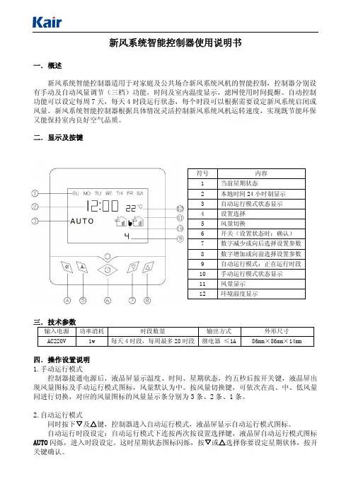
二.显示及按键符号 内容1当前星期状态2本地时间24小时制显示3自动运行模式状态显示4设置选择5风量切换6开关(设置状态时:确认)7数字减少或向后选择设置参数8数字增加或向前选择设置参数9自动运行模式:正在运行时段10手动运行模式状态显示11风量显示12环境温度显示三.技术参数输入电源 功率消耗 时段数量 输出方式 外形尺寸A C220V1w每天4时段,每周最多28时段 继电器 ≤1A86m m×86m m×14m m四.操作设置说明1.手动运行模式控制器接通电源后,液晶屏显示温度、时间、星期状态,约五秒后按开关键,液晶屏出现风量图标及手动运行模式图标,风量默认为中。
按风量切换键,可依次在高、中、低风量间进行切换,对应的风量图标的风量显示条分别为3条、2条、1条。
2.自动运行模式同时按下▽及△键,控制器进入自动运行模式,液晶屏显示自动运行模式图标。
自动运行时段设定:自动运行模式下连按两次按设置选择键,液晶屏自动运行模式图标A U T O闪烁,进入时段设定。
这时星期状态图标闪烁,按▽或△选择你要设定星期状体,按开关键确认。
星期状态确认后,自动进入这一天第1时段设定,这时液晶屏运行时段标显示1,时间的小时数字闪烁,按▽或△选择你要设定的时间,按开关键确认;小时确认后,自动进入分钟设定,这时时间的分钟数字闪烁,按▽或△选择你要设定的分钟,按开关键确认;时间设定确认后,自动进入风量设定,这时风量图标闪烁,按▽或△选择你要设定的风量(风量图标中无风量条表示关闭),按开关键确认,第一时段设定完毕,并自动进入第二时段设置。
新风系统说明书新风系统说明书1. 介绍新风系统是一种能够实现室内空气循环更新的系统。
它通过引入新鲜空气,并排出污浊的室内空气,达到改善室内空气质量的目的。
本文档将详细介绍新风系统的工作原理、安装步骤和使用方法。
2. 工作原理新风系统通过以下几个主要组件实现室内空气的循环更新:2.1 进风口进风口是新风系统的入口,通常安装在室外。
它负责引入外界新鲜空气,通过过滤器过滤掉空气中的颗粒物和污染物。
2.2 风机风机是新风系统的核心部件,它负责推动空气在系统中的流动。
风机通过吸入室内空气并经过处理后排出,同时也将新鲜空气推送到室内。
2.3 出风口出风口是新风系统的出口,通常安装在室内。
它负责排出室内污浊的空气,将其排到室外。
出风口通常配备有密封装置,以避免室内空气与室外空气直接混合。
3. 安装步骤3.1 开始安装前的准备工作在安装新风系统之前,需要进行以下准备工作:- 确定安装位置:通常新风系统的进风口和出风口需要分别安装在室外和室内,所以需要确定合适的位置进行安装。
- 准备安装材料:包括支架、连接管道、电源线等。
3.2 安装进风口和出风口根据确定的安装位置,使用支架将进风口和出风口固定在相应位置。
确保进风口与室外连接,出风口与室内连接。
3.3 安装风机将风机安装在合适的位置,并与进风口和出风口连接。
接通电源线,确保风机正常工作。
3.4 连接管道连接风机、进风口和出风口的管道,确保管道连接紧密,没有漏风现象。
4. 使用方法4.1 开启新风系统在需要循环更新室内空气的时候,将新风系统开启。
通常新风系统配备有开关按钮,通过按下按钮可以开启或关闭系统。
4.2 调节风速新风系统通常具备调节风速的功能。
用户可以根据需要选择合适的风速,以达到舒适的室内环境。
4.3 制定使用计划如果用户需要定时使用新风系统,可以设置使用计划。
新风系统通常配备有计时功能,用户可以设定每天的开启和关闭时间。
5. 注意事项- 定期清洁过滤器:为了保证系统正常工作和提高空气质量,需要定期清洁或更换过滤器。
griwind新风系统面板说明书Griwind新风系统面板说明书一、产品概述Griwind新风系统面板是一种用于控制新风系统运行的设备。
新风系统是一种能够将室外新鲜空气通过过滤和调节后送入室内的系统,可以改善室内空气质量,提供舒适的室内环境。
二、外观和结构1. 外观:Griwind新风系统面板采用简约而精致的设计,外观整洁、美观。
2. 结构:面板由高质量的材料制成,具有良好的耐久性和防护性能。
面板上配备了多个按键和显示屏,方便用户对新风系统进行操作和监控。
三、功能和特点1. 控制功能:面板上的按键和显示屏可以实现对新风系统的启停、风速调节、温度控制等操作。
2. 显示功能:面板上的显示屏可以显示当前的室内温度、湿度、风速等参数,帮助用户了解室内环境状况。
3. 定时功能:面板支持定时启停功能,用户可以根据需要设置新风系统的工作时间,提高能源利用效率。
4. 过滤功能:面板上的过滤器指示灯可以提醒用户更换过滤器,确保新风系统的正常运行和室内空气的质量。
5. 报警功能:面板具备故障报警功能,当新风系统出现故障时,面板会发出声光报警提示,提醒用户及时处理问题。
四、安装和使用1. 安装:请将Griwind新风系统面板安装在室内便于操作的位置,确保与新风系统的连接正确可靠。
2. 电源连接:将面板的电源线与交流电源连接,确保电源供应稳定。
3. 操作指南:按照说明书上的操作指南,正确使用面板上的按键进行相应的操作,如启停、风速调节、温度控制等。
4. 监控参数:通过面板上的显示屏,实时监控室内温度、湿度、风速等参数,根据需要调整新风系统的工作状态。
五、注意事项1. 请勿在湿度较高的环境中使用面板,以免影响其正常运行和寿命。
2. 面板应远离火源、水源等可能引起损坏或危险的物体。
3. 请勿私自拆卸或更换面板内部零部件,以免引起故障或安全隐患。
4. 面板应避免受到强烈的撞击或挤压,以免损坏外壳和内部电路。
5. 请定期清洁面板外壳,保持其外观整洁和使用寿命。

室内新风系统说明
书电子版
1
2020年4月19日
室内新风系统
使用说明书
中国建筑科学研究院
环境测控与优化研究中心
2020年4月19日
室内新风系统使用说明
一、产品构成及型号说明
室内新风控制系统是专门对室内空气质量进行检测和控制的系统,包括系统主机、控制分机和检测分机(如图1所示)。
具体的产品名称和型号如下:➢系统型号:CABR-EMCSO-S012
➢系统主机:CABR-EMCSO-S012A
➢控制分机:CABR-EMCSO-S012B
➢检测分机:CABR-EMCSO-S012C
1
2020年4月19日
图1 系统构成实物及连接示意图
2
2020年4月19日
系统简介
室内新风系统是专门改进室内空气环境设计研发的控制系统,该系统能够全面的检测室内空气质量,并上传系统主机,由内置的微控制芯片,智能的判断环境状态,如果出现CO2浓度超标等情况,系统会根据设置控制相应区域的风机作出相应的动作,实时的改进环境状态。
具体的系统具有以下突出的特点:
1、操作灵活简便:系统设计充分考虑了不同人
群的使用需求,运行做到了全自动化,设置
系统只需点击触屏,选择内置的运行模式,
即可满足用户不同的需求;
2、控制合理准确:检测系统采用高精度传感
器,能快速准确的检测室内的空气质量,同
时,根据设置,如果某些参数超过设置范
围,就会控制风机运转,以改进室内空气质
3
2020年4月19日。

系列新风系统用户手册1 前言 (3)1.1 机房环境要求 (3)1.2 专业节能新风系统 (3)2 产品介绍 (4)2.1 外观介绍 (4)2.2 型号说明 (4)2.3 主要特点 (5)2.4 标准组件 (5)2.4.1 风机 (5)2.4.2 滤网 (6)2.4.3 滤袋 (6)2.4.4 风阀 (6)3 技术参数 (7)3.1 机组参数 (7)3.2 使用条件 (8)4 尺寸参数 (8)4.1 机械尺寸 (8)4.2 底座安装尺寸 (9)4.3 新风管尺寸 (10)4.4 回风管尺寸 (10)4.5 维护空间 (11)4.6 安装考前须知 (11)5 应用指导 (12)5.1 显示屏 (12)5.1.1 显示屏按键说明 (12)5.1.2 系统启动界面 (12)5.1.3 待机界面内容 (13)5.1.4 菜单说明 (13)5.2 控制器 (15)5.2.1 主电路连接 (15)5.2.2 控制器原理框图 (16)5.3 新风机工作原理 (16)5.4 机房环境应用图例 (16)6 故障诊断与处理 (17)6.1 故障现象处置方法 (17)6.2 日常维护操作考前须知 (18)/ 、八—1 前言1.1机房环境要求现代计算机设备和数据交换设备均采用高热密度的CPU 芯片,单相机柜内的设备发热量也相应大幅提升,所以机房的提供的环境质量显得由为重要,主要表现在以下几个方面:a)温度控制:计算机及交换机工作时产生大量的热量,其密度是普通办公室的6〜20倍。
为了保证计算机设备能够发挥最正确效率,机房采用恒温控制,最正确控制范围为23C±2C(机房标准建议温度范围18C〜28 °C)o这就要求制冷机组一定要有足够的制冷能力和快速反响调控能力,以应对温度的急剧变化。
b)风量/洁净度控制:计算机及交换机工作时产生大量的显热,为了能迅速地排除这些热量,要求具有足够的冷却循环风量和足够的送风距离。
空调系统操作说明
一、供冷
开机:
1、确认系统管道已正确开启(需关闭板式换热器两端蝶阀),启动冷却塔风机观察电
流正常;然后启动冷却水泵、冷冻水泵,保证压力和压差正常。
2、机组送电,按控制面板上“0/1”键超过4秒,待显示“C L—ON”,且“C”闪烁,
按“”键确认,显示“ L—ON”,机组进入自检程序,约4-5分钟后各压缩机
根据负荷陆续启动。
关机:
1、按“0/1”键不超过4秒(按一下即可),显示“C LOFF”,约2分钟后各压缩机
陆续停机。
2、冷却泵、冷冻泵,冷却塔风机继续运行2—5分钟可停止。
二、供暖
开机:
1、确认系统管道已正确开启(需关闭空调主机两端蝶阀),检查热水罐中有足够热水
且温度正常;然后启动热循环水泵保证压力和压差正常。
2、如初次运行,需仔细观察压力表,如表针振动较大,可在系统排空处进行手动排空。
关机:
1、关闭热循环水泵后,即停止供热。
2、将热水机房内空调用热水罐与生活热水罐连通,以利用空调用热水罐内热水作为
生活热水使用。
注意事项:
1、酒店热水系统需保持恒压供水,凌晨会自动切换成小泵运行。
2、保证阀门处于正常位置,根据温度合理调整开启热水炉的台数;
3、可根据实际情。
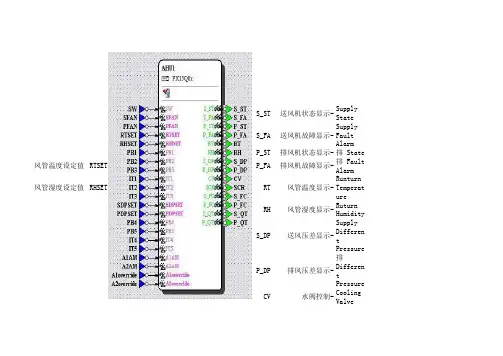
S_ST送风机状态显示-Supply StateS_FA送风机故障显示-Supply Fault AlarmP_ST排风机状态显示-排 State风管温度设定值RTSET P_FA排风机故障显示-排 Fault Alarm风管湿度设定值RHSET RT风管温度显示-Runturn TemperatureRH风管湿度显示-Ruturn HumidityS_DP送风压差显示-Supply Different PressureP_DP排风压差显示-排 Different PressureCV水阀控制-Cooling ValveSCR可控硅电加热控制-Semiconductor Controlled RectifierS_FC送风机控制-Supply Fan Control送风压差设定值SDPSET P_FC排风机控制-排 Fan Control排风压差设定值PDPSET S_QT送风机启停控制-Supply 启 停P_QT排风机启停控制-排 启 停面板操作:1,如图所示为液晶面板:按ESC进入主界面,长按回车键进入可编辑界面,会显示我们在程序中编写的简称,如第一页所示按上下左右键选择进入菜单,闪烁时按回车键,进入分级控制菜单,2,如图所示为液晶面板:进入分级菜单的界面后,观看参数,按回车键进入,光标会有闪动,按上下键可选择观看各种数据如果要改某项参数,再按下回车键,看到后面参数文字全部在闪烁,按上下键修改参数,修改完后按回车确认,返回上级按ESC退出即可自动调节控制风管温度设定值RTSET修改此参数后,控制器会自动计算并发送指令调节CV命令来调节水阀的开度。
风管湿度设定值RHSET修改此参数后,控制器会自动计算并发送指令调节SCR命令来调节水阀的开度。
送风压差设定值SDPSET修改此参数后,控制器会自动计算并发送指令调节S_FC命令来调节水阀的开度。
排风压差设定值PDPSET修改此参数后,控制器会自动计算并发送指令调节P_FC命令来调节水阀的开度。
赛菲新风机功能说明书(此说明书要适用无空调款机型)一、整机特性1、输入特性:输入端子L,N和接交流市电,为三个单插片6.3*0.8;系统工作电压为185V-240V/AC 。
2、性能指标1.控制器采用液晶显示2.控制板工作环境及储存要求:①工作温度:-20℃~85℃(室内机);②相对湿度:30~95RH?;③储存温度:-30℃~90;3.工作电压范围:185V-240V/AC;4.温度控制范围及控制精度:16℃~30℃?0.5℃,温度回差?1℃;5.温度显示范围:-30℃~90℃;6. 整机待机功率消耗:<2W;7. 电气控制部分要有良好的电磁兼容性能;8. 安全性能:符合GB4706.1-2005和GB4706.32-2005标准。
2、整机组成显示板GSC0040B电源控制板 GSC0040A变频板GSC0040CWIFI模块板GSC0040D液晶模组LCD-315A(黑底白字)粉尘传感器 PMS1003(客供)二氧化碳传感器 T6603客供温度传感器 4路(分别为新风入风口、排风入风口,新风出风口、室外排风出口)风机1 变频交流风机风机2 变频交流风机压缩机客供四通阀客供3、信号采集粉尘传感器 PMS1003(客供)(赛纳威备选数显)二氧化碳传感器T6603温度传感器 4路(分别为新风入风口、排风入风口,新风出风口、室外排风出口)二、净化机控制系统按键说明1、按键控制说明整机共有5个触摸按键,包含1个开关按键和4个功能键。
电源开关需用一个(橙蓝)双色发光二极管做出两种状态指示,其他按键由一个白色微蓝发光二极管做出状态指示。
所有正常按键操作都有提示音一声,提示操作有效(提示声音要选用美音或者由客户指定)。
2、开关键“”开关键的作用是切换控制板开机运行与待机状态。
机器通电后处于待机状态,屏幕和其他按键状态指示灯不亮,只有开关键亮橙色灯,指示整机现在处于待机状态,此时除开关键外其他按键均无效。
一旦按下开机键“”,音效提醒操作有效,开关键周围亮蓝色灯,控制板开机运行,此时所有按键指示灯和屏幕图标全亮3秒,然后按照实际运行功能键和图标亮灯,整机按默认的运行模式运行:风机风量为低风启动(默认上次风量)、PM2.5传感器、CO2传感器及各自检功能开启。
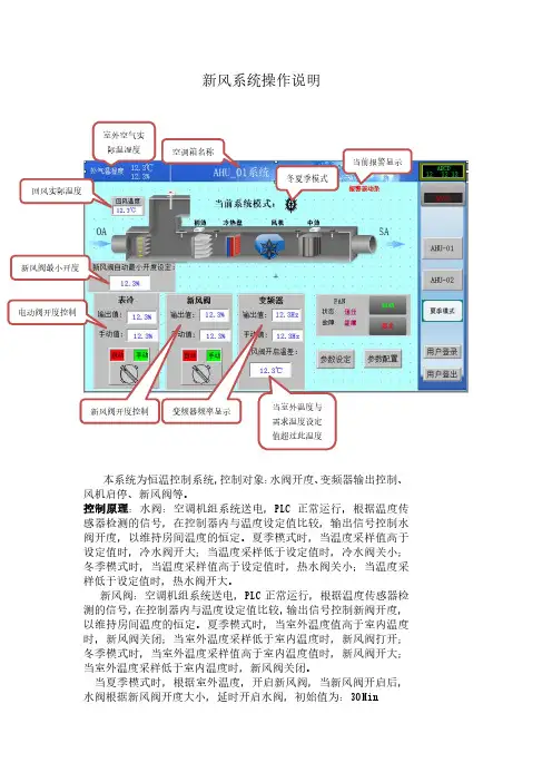
新风系统操作说明
本系统为恒温控制系统,控制对象:水阀开度、变频器输出控制、风机启停、新风阀等。
控制原理:水阀:空调机组系统送电,PLC 正常运行,根据温度传感器检测的信号,在控制器内与温度设定值比较,输出信号控制水阀开度,以维持房间温度的恒定。
夏季模式时,当温度采样值高于设定值时,冷水阀开大;当温度采样低于设定值时,冷水阀关小;冬季模式时,当温度采样值高于设定值时,热水阀关小;当温度采样低于设定值时,热水阀开大。
新风阀:空调机组系统送电,PLC 正常运行,根据温度传感器检测的信号,在控制器内与温度设定值比较,输出信号控制新阀开度,以维持房间温度的恒定。
夏季模式时,当室外温度值高于室内温度时,新风阀关闭;当室外温度采样低于室内温度时,新风阀打开;冬季模式时,当室外温度采样值高于室内温度值时,新风阀开大;当室外温度采样低于室内温度时,新风阀关闭。
当夏季模式时,根据室外温度,开启新风阀,当新风阀开启后,水阀根据新风阀开度大小,延时开启水阀,初始值为:30Min 室外空气实际温湿度 空调箱名称
冬夏季模式
当前报警显示
回风实际温度 新风阀最小开度
电动阀开度控制
新风阀开度控制
变频器频率显示 当室外温度与需求温度设定值超过此温度。
新风控制器软件功能说明
1、当室内TVOC(甲醛、苯、氨等挥发性有机气体)或PM2.5超过设定值时(设定值可人工设定)。
系统可通过单片机PWM输出控制直流风机实现空气污染指数的回路控制。
2、系统可实现自动循环定时控制(可人工设定开机时间和待机时间)
3、单片机应具备6路A/D 接口可实现 TVOC PM2.5 温度湿度的参数测量。
4、系统可实现风机运转的手动控制且在屏幕上显示有手动/自动状态。
5、系统主屏采用 LCM12864液晶显示,
6、主屏上应有滤网清洗提示功能
7、三色背光显示当前空气质量级别;
8、声音报警提示功能;
9、时间和星期显示功能;
10 信号采用无线传输方式。
用户手册2I n t r o d u c t i o n P a g e 引言你好,感谢你为你的房间选择Breezair®风管是冷气机。
Breezair®冷气机的设计将为你提供安静,可靠及凉快的舒适享受。
在Seeley 国际,我们选用质量最好的材料制造Breezair®蒸发式冷气机,设计出能满足多年经济、无障碍的冷却要求的产品。
请腾出一些时间来阅读此使用指南,你将能从中获得最大的收益。
Breezair®冷气机适用于挂墙恒温控制和遥控恒温控制。
请阅读本手册的相关部分关于如何运行各个系统的说明。
同时,请弄清楚你的冷气机的所有部件和特性。
将本指南保存在安全的地方以便进一步查阅。
为了安全起见,除非在监管下或经过装置应用指导,此装置不应由体能、感官或心智功能低下,以及缺少经验和有关知识的人(包括小孩)进行操作。
高效冷却为了实现高效的冷却或通风,建筑必须保证足够的向室外排气的出口。
打开的门和窗应离出风口尽可能远以助气流流动。
房间内排气出口面积约为出风口的2倍。
当建筑的设计无法提供足够的排风,应考虑机械排风,如安装排风机。
重要备注!在供水管可能由于低温而冻结的地区,安装时必须装设排空装置,再出现冻结前开启,以避免对冷气机的部件造成损害。
如果电源线损坏,必须更换由制造商或服务代理提供的特定电源线。
3R e m o t e T h e r m o s t a t C o n t r o l 遥控恒温控制遥控恒温控制器 挂墙恒温控制器 (遥控控制) (挂墙控制)4C o n t e n t s P a g e 目录遥控恒温控制...................................... 5 挂墙恒温控制...................................... 9 排水漏斗和排水阀............................ 13 电力中断............................................. 13 季节性维护......................................... 14 问题排查............................................. 16 维护与保修.. (18)5R e mo t eT h e rm o s t a t C o nt r o l 遥控恒温控制时间设定在设置其他程序之前先进行时间的设定。
1INSTRUCTION MANUAL - MODEL WCP-DAIR Wind Turbine Digital Control PanelThe wind generator digital control panel is fully calibrated and ready for installation. Please follow the instructions below for proper indoor installation. This manual covers 4-32 Amp rated WCP-D which is designed to operate with 12-48 VDC nominal battery banks.OVERVIEW:This control panel is designed to be installed indoors protected from weather. Installation requiresdrilling holes into the base of the plastic enclosure to allow for mounting and wiring.The Circuit Breaker switch is used to turn on and off the wind turbine control panel as well as provide protection in case of a major fault. The RUN-STOP toggle switch controls the operation of the wind turbine. In the RUN position, it allows the wind turbine to operate and produce power while in the STOP position it will electrically break the wind turbine stopping or stalling the rotation (in this mode some rotation may occur in windy conditions). The center position is the OPEN position, disconnecting thewind turbine from the battery bank but not brake the wind turbine. WARNING – the turbine should not be left in the Open Circuit/Middle position on the stop switch except during trouble shooting for short periods. The Digital display meter provides information on current (A), battery voltage (V), power (W) and wind generator energy production (W - hrs) over the recorded time-period.The WCP - D is designed and should be used only with the Primus AIR family of wind turbines. The WCP-D has 5 models and is specific to the Primus wind turbine. Primus wind turbines, such as the Air Breeze, Air 40, Air-X Marine, Air 30, AIR MaX and AIR Silent X, have built-in regulators allowing protection of the batteries from overcharging. If the wind turbine does not have a built-in regulator, an external diversion load controller will be required on the battery bank to provide proper protection from over charging.WarningDisconnect battery(s) prior to making connections. Secure the rotor blades of the wind turbine mechanically so that it is unable to rotate.MECHANICAL INSTALLATION:Locate a suitable mounting area for the WCP - D, preferably as close to the battery bank as possible where it will be interconnected yet where there is still easy access to view the meter and operate the controls.Enclosure Mounting: The enclosure of the control panel is designed to be mounted on a surface in the vertical position only. Additional holes are required to be drilled in the enclosure for mounting and wiring.1)Remove the cover off the enclosure base during the four corner screws.2)Identify a mounting location for the enclosure base. It is recommended the control panel be locatedas close to the battery bank as possible (7’ or less) for a more accurate reading of battery voltage.Mark and drill the enclosure back with holes adequate enough to mount the enclosure back to themounting area surface (hardware not included) for your specific location.3)D etermine optimum location to bring wires in and out of the enclosure. A 3/4” clear hole isrequired to secure the included wire bushings. Typically the wind generator input wire and batterywires are fed through the top, top one third sides of the enclosure or sometimes through bottom ofthe enclosure (see attached typical mechanical drawing locate the holes). When locating wirebushing holes try to position them so they are as close to the bottom of the enclosure as possibleallowing for easy wiring passage internally while not interfering with the internal circuits.2Recommend placing Holes on either Top or Bottom Ends of Enclosure4)Mount the now predrilled enclosure base into place. Insert wire bushings and pre-stripped wiresaccordingly.5)Make the connections as described in the section below, being sure that wires are routed internallyin the box to avoid interference with the internal components. The WCP terminal blocks, whichwill accept an 8 AWG or smaller wire size, provides for easy interconnect of the two turbine wiresand two battery power wires.6)Insert cover onto enclosure (it should easily fit in place, be cautious that the wires are notinterfering with the internal components or the cover) and secure with 4 original mounting screwsafter wiring is complete.ELECTRICAL INSTALLATION:Wind Generator Connection: Mechanically tie off the wind turbine blade so that it cannot operate while making your connections. Connect the wires of the 12-48V wind turbine feed wires to the terminals marked wind. Negative to -2 and Positive to 1+ of the Control Panel using the appropriate wire size (8 AWG or smaller) which the blocks will accept, see Figure 2. If a larger gauge wire is required, use a few inches of 8 AWG wire to transition to the terminal blocks. The green grounding wire of the wind generator is connected to the grounding system.WarningABYC STANDARDS AND PRACTICES should be followed during the installation along with the manufacturer’s recommendation. This manual is made available to assist during installation and start up and is not intended to supersede the ABYC Standards or the Manufacturers requirements and recommendations.34CautionWire size of the interconnect to both input (wind generator) and output (battery bank) of the control panel is critical to the proper operation of the wind generator. Please consult a Wire Sizing Table (Primus AIR Manual) to be sure you have the minimum wire size so that the voltage drop is less than 3%.1) Battery Connections: Be sure battery feed wires are not connected to the battery at this time. Connect the battery feed wires to terminals marked Battery with Negative to -4 and Positive to 3+ of the control panel using the appropriate wire size (see Figure 2) .WarningIt is strongly recommended to recheck the tightness of the screwson the terminal block where the connections are made. Initially, tight screw connections will loosen as the wire compresses and therefore going back to recheck the tightness of the screws after a period of time will help assure a good connection.2) Mounting: Mechanically install the panel into the enclosure base using all 4 cover screws.3) Battery Connection: Verify the Circuit Breaker on the Control Panel is in the “OFF” position. Set the RUN –STOP switch in the “STOP” position. Connect the battery feed wires from the Control Panel to the battery bank terminals. Make sure all connections are tight and the wires are of proper size and are mechanically secured.WarningPlease be sure polarity (negative/positive) is correct, if not it will damage the control panel and the wind turbine voiding warrantee.START UP:Remove the mechanical tie off of the wind turbine so that it can spin freely. It should rotate at this point (if wind present) but have some resistance (Run-Stop switch is in the “STOP” position).Turn Circuit Breaker to the “ON” position. The digital meter should illuminate and indicate battery system voltage. No current or wattage would be displayed at this time. If there is an energy value displayed, reset to zero by following procedure in section marked “Energy Display/Reset” Switch the RUN-STOP switch to the “RUN” position. The wind turbine should begin turning and current should be displayed provided the battery bank is at 85% or less – not in regulation (please refer to Primus manual for battery regulation set points).Figure 2If the battery b ank is “topped off” or fully charged, the wind generator regulator will prevent the wind generator from rotating. The wind turbine LED should blink and if there is sufficient wind it should begin spinning and current should be displayed provided the battery bank is at 85% or less. Please see the Primus AIR instruction manual that came with the wind generator for more information.WarningSet the wind generator RUN-STOP switch in the “STOP” position prior to turning off or on the power circuit breaker.In order for the Hybrid energy systems to be operational, the circuit breaker must be left in the “On”position which allows the wind generator to be applying energy to the battery bank when wind is available. Leaving the circuit breaker “on” and wind circuits active will deplete only a minor amount of energy from the battery during non-energy producing periods and should not be of concern. The wind system typically works in harmony together with other energy producing systems on board such as solar PV, alternator or AC powered battery charger and therefore it is not necessary to turn “off” the wind circu it breaker when these are active (refer to PWP instruction manual for more information).NoteIt is strongly recommended the installer/user read the PWP instruction/start up manuals prior to powering up the WCP - D and related equipment. Adjustments may be necessary based on the type of batteries in the system and other optional features which may be needed for your particular installation.DISPLAY OPERATION:Backlight Control: short press the small button located on the right side of the display to turn on or off the backlight. The backlight has a memory function and therefore it will keep your setting even after it powered off.Energy Display/Reset: The energy information on the display represents a cumulative amount of energy production from its prior reset. To reset it back to zero complete the following steps:1.Long press the button on display until the power display area reads “CLr” and then release the button.2.The energy display will begin flashing indicating it in the reset mode. Short press the button again and theenergy value should be cleared and it should automatically exit the flashing reset mode.3.If there is no activity within 5 seconds, it means the energy value has not been clear and the meter willautomatically exit the energy reset mode.4.If the value has not cleared to zero then repeat step #1 to make a second attempt to clear the reset of theenergy value.The Energy value is accumulated number (Energy = Power x Time). It will be maintained in the memory of the meter even if circuit breaker is turned off. A manual Energy value reset of the display will be necessary if you want to have a new Energy value.Set Voltage Alarm: The display meter has built in high and low-voltage alarms. If you wish to adjust them from the default follow the below instructions:51.Long press the button to the right of the display until the power display area reads “SET” then release thebutton.2.The Voltage display will show the high voltage alarm value, the Current display will show the low voltagealarm value and the last digit begins to flash. Short press the button to advance the setting. When there is no button activity over 3 seconds the meter will switch to the next digit automatically from the Highvoltage alarm value to the Low voltage alarm., There are a total of 6 digits the range of voltage alarm can be set from 6.5 to 99.9 V3.After completing your adjustments for the alarm setting, long press the button until the screen displays passwhich means you set the successfully the voltage alarm and it will automatically exit the setting state.WarningThe meter is set up from the factory to work with a 50A shunt which is built into the controller. If the button is held to long the power area may begin displaying CURR which can allow accidental adjustment of the shunt setting. Do not change the setting of 50A as it will put the meter out of calibration. To exit this mode, long press the button to exit back to normal display.TROUBLESHOOTING:1.Wind Turbine is Cycling On/Off: When your battery bank is approaching top off (full charge), you may seethe wind turbine starting and stopping very frequently. This is caused by the wind turbine attempting to do the final top off on to your battery bank. It may be necessary to lower the voltage set point for the wind generator regulator to eliminate this problem. See the PWP instruction manual for more information.2.Wind Turbine Not Operating Properly: Primus Wind Power AIR wind turbines contain a microcontrollerfor operating/regulation. From time to time transients or electrical noise (i.e. lightning strikes, keying the SSB microphone, etc.) may cause these microprocessors to go unstable. To correct the problem turn the WCP – D Stop/Run switch to Stop, wait approximately 5 minutes and then set it back to Run. If this does not resolve the problem, please refer to the PWP manual for additional troubleshooting advice or contact PWP Tech support. 3. Display Blank: Complete the following steps:3.1.Check that the DC circuit breaker is in the ON position.3.2.Confirm that the correct DC voltage is applied to the controller by checking the battery terminals insidethe controller (use a voltmeter) after you have removed it from its enclosure base.3.3.If the display is still blank after you confirm voltage is applied to the controller and the DC breaker on thecontroller has been turned ON then check the fuse.3.4.Fuse check. Remove power from the controller, unscrew the fuse holder and check the fuse for continuity.If the fuse has failed the continuity check replace the fuse and repower the controller.3.5.If the controller display is still blank, controller requires servicing.6WCP HOOKUP DIAGRAMNotes:WCP-8)7。
BRC301H611说明书
一、基本功能
1、开启/关闭新风:点击右上方的开关键,开启或关闭新风系统。
2、模式选择:点击模式转换键,选择自动、热交换、旁通模式。
3、风量调节:点击风量键,进行风量调节。
4、定时功能:点击定时键,选择定时开货定时关,点击上下键设定时间。
二、雾霾天
遇到雾霾天时,担心PM2.5进到房间,点击风量键,选择FRESH UP,室内保持正压,有效阻止脏空气的进入。
三、过度季节使用技巧
温度适宜的日子里,只需点击模式转换键,选择旁通模式。
旁通模式下,空气不经过热交换元件,而做旁通流过进行通风,不开窗呼吸新鲜空气,保持清醒头脑。
绿岛风新风系统控制面板说明书
绿岛风新风系统控制面板操作:
1、开关:顾名思义,开机和关机;
2、模式:模式选择中,点击可切换暖风和冷风;
3、风速:绿岛风新风系统风速一般分为高速、中速、低速、自动四个档位,制冷制热可根据个人需求进行调节,点击切换各档位;
4、温度调节:温度调节为两个按钮,一个是加温,另一个是降温,绿岛风新风系统的设置为最高30℃,最低16℃。
5、绿岛风新风系统使用一般都有制冷和制热的功能,格力的使用上会有一个“模式”的按键,按下这个键之后,显示屏就会出现“雪花”的图案。
看到雪花图案之后,就可以松手了。
这已经是进入了制冷模式了。
在模式键的四周围,是有一些三角形的按键的,这些三角形的方向分别是上下左右。
如果想要温度上升,就按“上”,如果想要温度下降,就按“下”。
根据自己想要的温度进行调节;
6、如果想要进行制热,这样操作:也是按下“模式”键,看到显示屏上“太阳”出现了就可以松手是,也是使用“上”“下”进行调节温度;
7、想要设定除湿的话,和上面的操作方法一样,按住“模式”键,等出现了“水滴”图案就松手。
在“上”“下”这两个按键里进行调节;
8、想要设置送风的话,和上面的步骤是一样的。
调节到自己想要的温度就可以了;
9、绿岛风新风系统使用是有很多的图标的,“树叶”的图标是健康模式的,制冷不好,想取消的话按多一下“健康”就可以了。
“雪花”是制冷。
“太阳”是制热模式。
另外,还有一个“三角循环”的图标,这个而是循环风,而“风扇”是自然风,“水滴”就是除湿了。
采用有线温控器和无线遥控器对绿岛风新风系统进行控制。
主机温控器安装在室内主机下方的墙壁上,直接控制主机的开关。
温控器可以设定温度、定时,并选择运行模式(制冷、制热、除湿、送风、睡眠等);无线遥控器用来在5米左右的距离内遥控主机温控器,同样能达到控制主机的目的。
家用绿岛风新风系统控制面板—绿岛风新风系统可以使每个房间都自由控温
使用家用绿岛风新风系统后,每个房间能自由调温,家用绿岛风新风系统基本都是分户控制,各户的总控制阀在室外管道井,开通或维修均需由物业专业人员进行。
进入室内,各风机处均有各自的开关阀门,通常在业主交房时打压试验后就保持常开状态。
每个房间都分别安装手动的风口开头或者电子温控器,用户可以随意调节各个房间的温度。
注意在温度调节时,室内温度宜设定在24℃-28℃左右,室内外温差不宜超过7℃。
家用绿岛风新风系统拥有非常多不同的产品,适合于多种不同的情境下使用,很多人都有在自己的家庭中安装使用,给我们大家带来
了非常好的室温调节效果。
而本次为大家介绍的这些家绿岛风新风系统的控制面板的使用方法,大家可以简单的参考了解,在以后如果要购买家用绿岛风新风系统来使用的话,一定要仔细了解家用。
绿岛风新风系统控制面板的功能情况,只有这样才能够让我们大家在使用绿岛风新风系统的时候得到一个非常更好的使用效果。