新风全热交换器液晶控制器EK说明书
- 格式:doc
- 大小:419.50 KB
- 文档页数:2

智能新风控制系统使用说明书产品概览智能新风控制系统是新风到家推出的一套新风解决方案,通过监测控制器(空气监测仪)与新风机的联动,实时监测室内PM2.5、CO2浓度,输出信号直接控制新风机的启动及转速。
新风机通过监测结果智能运行,有效的改善室内空气污染,提高空气质量,加速室内空气的流通、污染空气的排出,加入室外新鲜空气的注入,实现既节能环保又能保持室内良好空气品质。
室外PM2.5开关键风速键模式键需连网:控制器连接WiFi 新风机与控制器关联新风机控制器主要功能说明内循环开启条件当室内CO2小于800当室内CO2大于1500当室内CO2小于650当室内CO2小于600当室内CO2大于1000当室内CO2大于800外循环开启条件模式名称经济舒适豪华点击“开关键”一次风阀打开,再点击一次风阀关闭手动摸下,点击“风速键”选择风速:风速1 风速2 风速3 风机停自动模式下,开启外循环以CO2阈值为唯一标准,设置步骤如下: 自动模式下,空气品质为差时,风速根据PM2.5/CO2的预设参数自动切换为高速风 阈值设置操作步骤如下:a 点击设置键进入设置界面b 进入设置页面,选择阈值设置c 在阈值设置界面中选择PM2.5和CO2阈值设置进入,对调节参数进行设置,注:自动模式由PM2.5和CO2的调节值共同参与控制风速a 点击设置键进入设置界面b 进入设置页面,选择背光设置c 在背光设置界面点击“定时熄屏/亮屏设置”,点击界面中的数字修改熄屏/亮屏时间a 根据阈值设置步骤进入阈值设置页面b 进入阈值设置页面,选择内循环模式设置c 对内循环模式(经济、舒适、豪华)进行选择,三个模式对应以下参数: 点击“模式键”选择模式:自动/手动系统默认定时熄屏时间为21:00 定时亮屏时间为07:00 根据以下步骤进行设置:控制器配置网络步骤一 使用微信扫描控制器底部的二维码绑定设备设备二维码提示:配置前请确保控制器电量充足(建议连接USB电源使用),并将手机连接WiFi步骤二 微信端点击“进入公众号”按钮,进入公众号步骤三 从公众号底部菜单“我的设备”进入设备详情,此时设备为未联网状态,根据界面提示,点击“配置网络”按钮步骤四 界面中出现配网弹窗提示,按照提示内容对控制器进行相应的操作步骤五 在进入的配置页面中输入WiFi密码(手机连接的WiFi),输入完后点击“连接”提示:配置成功后,微信界面自动返回设备详情页,数据正常显示,控制器室外数据正常显示;若60秒内配置失败,此时需再次长按控制器WiFi按钮进入配网模式为设备配网。
新风系统智能控制器使用说明书一.概述新风系统智能控制器适用于对家庭及公共场合新风系统风机的智能控制,控制器分别设有手动及自动风量调节(三档)功能,时间及室内温度显示,滤网使用时间提醒。
自动控制功能可以设定每周7天,每天4时段运行状态,每个时段可以根据需要设定新风系统启闭或风量。
新风系统智能控制器根据具体情况灵活控制新风系统风机运转速度,实现既节能环保又能保持室内良好空气品质。
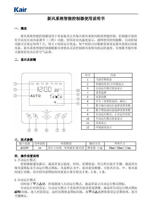
二.显示及按键符号 内容1当前星期状态2本地时间24小时制显示3自动运行模式状态显示4设置选择5风量切换6开关(设置状态时:确认)7数字减少或向后选择设置参数8数字增加或向前选择设置参数9自动运行模式:正在运行时段10手动运行模式状态显示11风量显示12环境温度显示三.技术参数输入电源 功率消耗 时段数量 输出方式 外形尺寸A C220V1w每天4时段,每周最多28时段 继电器 ≤1A86m m×86m m×14m m四.操作设置说明1.手动运行模式控制器接通电源后,液晶屏显示温度、时间、星期状态,约五秒后按开关键,液晶屏出现风量图标及手动运行模式图标,风量默认为中。
按风量切换键,可依次在高、中、低风量间进行切换,对应的风量图标的风量显示条分别为3条、2条、1条。
2.自动运行模式同时按下▽及△键,控制器进入自动运行模式,液晶屏显示自动运行模式图标。
自动运行时段设定:自动运行模式下连按两次按设置选择键,液晶屏自动运行模式图标A U T O闪烁,进入时段设定。
这时星期状态图标闪烁,按▽或△选择你要设定星期状体,按开关键确认。
星期状态确认后,自动进入这一天第1时段设定,这时液晶屏运行时段标显示1,时间的小时数字闪烁,按▽或△选择你要设定的时间,按开关键确认;小时确认后,自动进入分钟设定,这时时间的分钟数字闪烁,按▽或△选择你要设定的分钟,按开关键确认;时间设定确认后,自动进入风量设定,这时风量图标闪烁,按▽或△选择你要设定的风量(风量图标中无风量条表示关闭),按开关键确认,第一时段设定完毕,并自动进入第二时段设置。
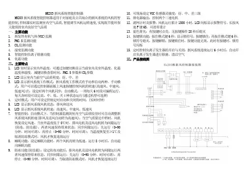
MK203新风系统智能控制器MK203新风系统智能控制器适用于对家庭及公共场合的新风系统的风机的智能控制,控制器实时监测室内空气品质,智能调节风机运转速度,实现既节能环保又能保持室内良好空气品质一、主要功能1.挥发性有机气体(VOC)监测2.PM2.5监测功能3.CO2监测功能4.湿度监测功能5.智能控制负离子除菌功能6.化霜功能二、主要特点1.LCD实时显示室内外温度:可通过加键切换显示当前室内及室外温度、化霜温度和湿度,减键切换查看时间、PM2.5参数和CO2参数2.LCD显示室内当前空气品质程度:好、中、差3.LCD显示新风系统工作模式:新风系统工作模式有手动和自动两种。
手动模式:用户可以通过控制器面板上风速按键控制风机的转速(高速风、中速风、低速风)注:设定时两个风机同步;自动模式:一周每天6时段可编程运行,每天各时段可设定高、中、低、关4种状态运行(通过机型可选择)4.定时模式:用户可设定控制定时启动和关闭的时间;(实时时钟)5.LCD 显示新风系统风机状态:排风和送风6.LCD 显示新风系统风机转速:高速风、中速风、低速风7.智能控制:自动模式下,当控制器监测到室内空气品质较差时可自动调整新风系统风机转速(排风及送风自动转为高速风);当空气质量达中档时,风机恢复设定风速。
当室外温度低于0℃时,排风电机及送风电机转为间隙运行(防冻、防结霜),两者风速保持原来状态,同步间隙运行:先运行(0-90分钟,时间可调),再停止(0-90分钟,时间可调);当温度恢复至≥1℃及取消防冻模式时,风机才恢复连续运行8.睡眠功能:设定睡眠功能时,两个风机均转为低速,运行8小时后,自动退出睡眠功能9.防冻功能(防结霜):设定防冻功能后,排风电机及送风电机转为间隙运行两者风速保持原来状态,同步间隙运行:先运行(0-90分钟,时间可调),再停止(0-90分钟,时间可调),当取消防冻模式时,风机才恢复连续运行10.可现场设定VOC传感器灵敏度:好、中、差三级11.继电器输出:控制两个三速电机12.滤网计时及报警:风机运行累计1500小时,LCD闪烁显示报警符号。

INSTALLATION MANUAL EKRTW4PW44896-1C 1Contents1. Introduction (1)2. Installation of EKRTW (2)3. Setting up codes in the installer menu (5)4. T echnical characteristics (10)1.IntroductionThe room thermostat EKRTW can be used to control floor heating-only applications and floor heating/cooling applications. It is typically connected to the indoor unit. Refer to the "T ypical application examples" in the Installation manual of the indoor unit.■In case of floor heating-only applications the room thermostat can also be connected to the individual motorized valve of the floor heating loop.■If a floor heating-only application is used in combination with fan coil units each fan coil unit should have its dedicated fan coil thermostat.2.Installation of EKRTWThe EKRTW thermostat is wall-mounted, with supplied screws and plugs. Refer to figure 1.Cabling towards the indoor system (field supply) should be foreseen in advance taking the suggestions for an ideal installation location into account. Refer to figure 2.1At the left of the thermostat, gently push the lid.2Remove the front cover by pulling it towards you.3Unscrew the screw of the cable holder in the bottom left corner of the back part of the thermostat and remove the transparent cable protection.4Remove the battery insulator.5Drill holes in the wall taking the dimensions of the thermostat into account and insert the supplied plugs in the holes.Refer to figure 3 (unit of measurement: mm).24PW44896-1C4PW44896-1C36Pass the indoor unit or motorized valve wiring through the back of the thermostat.7According your application, perform the wiring.7a When connected to the indoor unit, wire the indoor unit andthe thermostat as shown below.For heating-only applications, wire 17-C or 2-C is not to be installed.Use wire size 0.75~1.50 mm 2.EKHB(H/X)007AC***EKHB(H/X)008EKHB(H/X)016H Heating demand CCooling demand7b When connected to the motorized valve, wire the motorized valve and the thermostat as shown below (for heating-only applications).The output relays (H and C are voltage-free contacts) can handle a maximum load of 5 A - 230 VAC.8Fasten the thermostat with the supplied screws.9Put the transparent cable protection back into place and fix the cable protection with the screw.10Close the thermostat cover.11Remove the protective film from the LCD.44PW44896-1C4PW44896-1C53.Setting up codes in the installer menuY ou can set up codes, starting from the time and date menu (in advanced mode).1Activate the advanced mode by pressing > during 5seconds in OFF mode (D ).2Navigate to the date and clock setting menu (G ) by pressing >.3Press > and keep it pressed while now pressing =during 10 seconds.y is displayed next to 4®.4Press < or > to consult the current settings of the codes.5T o modify codes, press +, - or =.The value is flashing when being modified.6Press + or - to increase or decrease the code value by 1 step.T o put a code back to its default value, press + and - at the same time.7Press = to save your selection.Y ou can exit this code menu by going to the "/" code and pressing =.3.1.Set-up for heating/cooling applicationsFor heating/cooling applications, set the following codes:64PW44896-1C4PW44896-1C 784PW44896-1C4PW44896-1C 9104PW44896-1C4.Technical characteristicsT emperature read out Steps of 0.1°C Operating temperature 0°C~50°CSetpoint temperature range4°C~37°C in steps of 0.5°CElectrical protectionClass II - IP30 (indoor use, polution degree 2)Feeding and autonomy 3 alkaline batteries AA.LR6 1.5 Vapproximately 2 years (depending on usage conditions)Output relays Maximum load 5 A - 230 VAC Immunity against voltage surgesCategory III (2.5 kV)T ype of automatic action of the thermostat1CNOTESC o p y r i g h t ©D a i k i n4PW44896-1C。
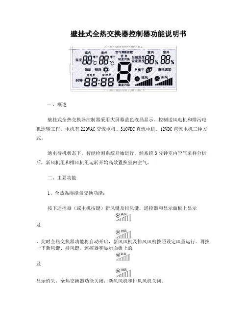
壁挂式全热交换器控制器功能说明书一、概述壁挂式全热交换器控制器采用大屏幕蓝色液晶显示。
控制送风电机和排污电机运转工作。
电机有220VAC交流电机、310VDC直流电机、12VDC直流电机三种方式。
通电待机状态下,智能检测系统开始运行,经系统3分钟室内空气采样分析后,新风机组和排风机组运转开始高效置换室内空气。
二、主要功能1、全热温湿能量交换功能:按下遥控器(或主机按键)新风键及排风键,遥控器和显示面板上显示及,此时全热交换器功能将自动开启,新风风机及排风风机按照设定风量运行。
再按一下新风键、排风键,遥控器和显示面板上的及显示消失,全热交换器功能关闭,新风风机和排风风机关闭。
关于全热温湿能量交换功能:采用全球顶级的能量交换系统,能够有效进行空气中温湿交换,效率比普通的能量交换系统提高了41.5%,节能效率高达77.5%!有效节约空调能量和暖气能量,利用此能量交换系统,可以大大降低能耗,而且减少了空调和暖气的使用量。
特别提示:新风和排风未能同时开启时,全热交换功能将不能正常工作。
2、负离子功能按下遥控器(或主机按键)负离子键,遥控器和显示面板上分别显示,负离子发生器开始工作,开始负离子功能。
再按一下负离子键,遥控器和显示面板上图标消失,负离子发生器断电,负离子功能取消。
关于负离子功能:负离子发生器能激发大量的负氧离子,有效平衡空气中正负离子的浓度,负离子又称“空气维生素”,有杀菌、除尘作用,使空气变得清新健康,健康富含负离子空气,能中和乳酸、均衡大脑血清素的浓度,抑制压力荷尔蒙和疲劳物质的分泌,缓和精神紧张和急躁感,使人体充满活力。
特别提示:负离子功能只有在新风机组正常开启下方可操作。
3、新风功能按下遥控器(或主机按键)的新风键,遥控器和显示面板上分别显示,新风风机按照设定风量运行。
再按一次新风键,遥控器和显示面板上显示消失,新风风机关闭。
三、辅助功能1、极寒排污功能按遥控器(或主机按键)排风键,遥控器和和显示面板上分别显示,排风风机按照设定风量运行,排风功能开启,再按一下排风键,遥控器和显示面板上显示消失,排风风机关闭,排风功能取消。
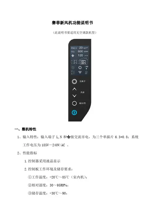
赛菲新风机功能说明书(此说明书要适用无空调款机型)一、整机特性1、输入特性:输入端子L,N和接交流市电,为三个单插片6.3*0.8;系统工作电压为185V-240V/AC 。
2、性能指标1.控制器采用液晶显示2.控制板工作环境及储存要求:①工作温度:-20℃~85℃(室内机);②相对湿度:30~95RH ;③储存温度:-30℃~90;3.工作电压范围:185V-240V/AC;4.温度控制范围及控制精度:16℃~30℃±0.5℃,温度回差±1℃;5.温度显示范围:-30℃~90℃;6. 整机待机功率消耗:<2W;7. 电气控制部分要有良好的电磁兼容性能;8. 安全性能:符合GB4706.1-2005和GB4706.32-2005标准。
2、整机组成显示板GSC0040B电源控制板 GSC0040A变频板GSC0040CWIFI模块板GSC0040D液晶模组LCD-315A(黑底白字)粉尘传感器 PMS1003(客供)二氧化碳传感器 T6603客供温度传感器 4路(分别为新风入风口、排风入风口,新风出风口、室外排风出口)风机1 变频交流风机风机2 变频交流风机压缩机客供四通阀客供3、信号采集粉尘传感器 PMS1003(客供)(赛纳威备选数显)二氧化碳传感器T6603温度传感器 4路(分别为新风入风口、排风入风口,新风出风口、室外排风出口)二、净化机控制系统按键说明1、按键控制说明整机共有5个触摸按键,包含1个开关按键和4个功能键。
电源开关需用一个(橙蓝)双色发光二极管做出两种状态指示,其他按键由一个白色微蓝发光二极管做出状态指示。
所有正常按键操作都有提示音一声,提示操作有效(提示声音要选用美音或者由客户指定)。
2、开关键“”开关键的作用是切换控制板开机运行与待机状态。
机器通电后处于待机状态,屏幕和其他按键状态指示灯不亮,只有开关键亮橙色灯,指示整机现在处于待机状态,此时除开关键外其他按键均无效。


User ManualEKI-2726FHPI4 10/100/1000T + 2 1000 Mini-GBIC with 4 IEEE 802.3at HighPower PoE Industrial WideTemperature SwitchCopyrightThe documentation and the software included with this product are copyrighted 2012 by Advantech Co., Ltd. All rights are reserved. Advantech Co., Ltd. reserves the right to make improvements in the products described in this manual at any time without notice.No part of this manual may be reproduced, copied, translated or transmitted in any form or by any means without the prior written permission of Advantech Co., Ltd.Information provided in this manual is intended to be accurate and reliable. However, Advantech Co., Ltd. assumes no responsibility for its use, nor for any infringements of the rights of third parties, which may result from its use. AcknowledgementsIntel and Pentium are trademarks of Intel Corporation.Microsoft Windows and MS-DOS are registered trademarks of Microsoft Corp.All other product names or trademarks are properties of their respective owners. Product Warranty (5 years)Advantech warrants to you, the original purchaser, that each of its products will be free from defects in materials and workmanship for five years from the date of pur-chase.This warranty does not apply to any products which have been repaired or altered by persons other than repair personnel authorized by Advantech, or which have been subject to misuse, abuse, accident or improper installation. Advantech assumes no liability under the terms of this warranty as a consequence of such events.Because of Advantech’s high quality-control standards and rigorous testing, most of our customers never need to use our repair service. If an Advantech product is defec-tive, it will be repaired or replaced at no charge during the warranty period. For out-of-warranty repairs, you will be billed according to the cost of replacement materials, service time and freight. Please consult your dealer for more details.If you think you have a defective product, follow these steps:1.Collect all the information about the problem encountered. (For example, CPUspeed, Advantech products used, other hardware and software used, etc.) Noteanything abnormal and list any onscreen messages you get when the problemoccurs.2.Call your dealer and describe the problem. Please have your manual, product,and any helpful information readily available.3.If your product is diagnosed as defective, obtain an RMA (return merchandizeauthorization) number from your dealer. This allows us to process your returnmore quickly.4.Carefully pack the defective product, a fully-completed Repair and ReplacementOrder Card and a photocopy proof of purchase date (such as your sales receipt)in a shippable container. A product returned without proof of the purchase dateis not eligible for warranty service.5.Write the RMA number visibly on the outside of the package and ship it prepaidto your dealer.Part No. Edition 2Printed in Taiwan August 2012EKI-2726FHPI User Manual iiDeclaration of ConformityFCC Class AThis Equipment has been tested and found to comply with the limits for a Class-A digital device, pursuant to Part 15 of the FCC rules. These limits are designed to pro-vide reasonable protection against harmful interference in a residential installation.This equipment generates, uses, and can radiate radio frequency energy. It may cause harmful interference to radio communications if the equipment is not installed and used in accordance with the instructions. However, there is no guarantee that interference will not occur in a particular installation. If this equipment does cause harmful interference to radio or television reception, which can be determined by turning the equipment off and on, the user is encouraged to try to correct the interfer-ence by one or more of the following measures:⏹Reorient or relocate the receiving antenna.⏹Increase the separation between the equipment and receiver.⏹Connect the equipment into an outlet on a circuit different from that to which thereceiver is connected.⏹Consult the dealer or an experienced radio/TV technician for help.CEThis is a Class-A product. In a domestic environment this product may cause radio interference in which case the user may be required to take adequate measures. Advantech Customer ServicesEach and every Advantech product is built to the most exacting specifications to ensure reliable performance in the unusual and demanding conditions typical of industrial environments. Whether your new Advantech equipment is destined for the laboratory or the factory floor, you can be assured that your product will provide the reliability and ease of operation for which the name Advantech has come to be known.Your satisfaction is our number one concern. Here is a guide to Advantech's cus-tomer services. To ensure you get the full benefit of our services, please follow the instructions below carefully.Technical Support and Assistance1.Visit the Advantech web site at where you canfind the latest information about the product.2.Contact your distributor, sales representative, or Advantech's customer servicecenter for technical support if you need additional assistance. Please have thefollowing information ready before you call:–Product name and serial number–Description of your peripheral attachments–Description of your software (operating system, version, application software, etc.)– A complete description of the problem–The exact wording of any error messagesiii EKI-2726FHPI User ManualEKI-2726FHPI User Manual ivContentsChapter1Introduction (1)1.1Overview (2)1.2Features (2)1.3Packing List (2)Chapter2Hardware Description (3)2.1Physical Dimensions (4)2.1.1LED Indicators (4)Table 2.1:EKI-2726FHPI LED Indicators (4)2.2RJ-45 Pin Assignments (5)Chapter3Installation (7)3.1DIN-Rail Mounting (8)3.1.1Assembling the DIN-Rail Clip (8)Figure 3.1Rear side of the Switch (8)3.1.2Hanging the Industrial Switch (9)3.2Wall Mounting (10)3.3Grounding the Industrial Switch (11)3.4Wiring the Power Inputs (11)Figure 3.2Plugs for Power 1 & Power 2 (11)Figure 3.3Captive Screws for Fixing Wires (12)3.5Wiring the Fault Alarm Contacts (12)Figure 3.4Terminal Block Plugs for Fault Alarm Contacts (12)Figure 3.5Fault Alarm Wiring Example (12)3.6Ethernet Cabling (13)3.6.1Connecting the SFP Port (13)Figure 3.6Transceiver to the SFP slot (13)Figure 3.7Transceiver Inserted (13)Figure 3.8LC connected to the transceiver (14)3.6.2Disconnecting the SFP Port (14)Figure 3.9Remove LC connector (14)Figure 3.10Pull out from the SFP slot (14)Appendix A Troubleshooting (15)A.1Troubleshooting (16)Appendix B Technical Specifications (17)B.1Technical Specifications (18)v EKI-2726FHPI User ManualEKI-2726FHPI User Manual viChapter11.1OverviewThe High-Power PoE Industrial Switch is a cost-effective solution, which meets the high reliability requirements demanded by industrial applications. To solve the incon-venience of wall outlet access, the equipment is designed with power over Ethernet ports that comply with the IEEE 802.3at standard providing power as well as data over the conventional RJ-45 cables to the connected Powered Devices which need higher power consumption.1.2Features⏹System Interface/Performance–RJ-45 ports support Auto MDI/MDI-X Function–Embedded 4-port PoE Injection–Store-and-Forward Switching Architecture–Back-plane (Switching Fabric): 12Gbps–MAC Address Table with 8K entries⏹Power Input–DC 48V Redundant Power Input⏹Case/Installation–IP-30 Protection–Installation in a Pollution Degree 2 environment–DIN-rail and Wall mountings Design1.3Packing ListPlease refer to the package contents list below to verify them against the checklist.⏹PoE Industrial Switch x 1⏹User manual (CD-ROM) x 1⏹Removable Terminal Block x 1⏹Wall-mount Kit (2 wall-mount brackets with screws) x 1EKI-2726FHPI User Manual2Chapter2In this chapter, the Industrial switch's dimensions, definitions for LED indicators, cabling information, and wiring installation will be described.2.1Physical DimensionsThe PoE Industrial Switch dimensions (W x H x D) are 59.6mm x 152mm x 105mm as the figure shown below.2.1.1LED IndicatorsThe diagnostic LED indicators located on the front panel of the industrial switch pro-vide real-time system information and operation status. The table below provides the description status and definitions of the LED indicators for the switch.LED Color DescriptionPower1Green On Power input 1 is active Off Power input 1 is inactivePower2Green On Power input 2 is active Off Power input 2 is inactiveP-Fail Red On Power input 1 or 2 has failed Off No failure occursPoE indicator (Port 1 ~ 4)GreenOnThe port is supplying power to the powered-deviceOffNo powered-device attached or power supplyingfails1 ~ 4 (RJ-45)Green(upper)On Connected to networkFlashing Networking is activeOff Not connected to network Green(lower)On1000MOff100/10M5, 6 (mini-GBIC)Green On Connected to network Flashing Networking is activeOff Not connected to networkEKI-2726FHPI User Manual45EKI-2726FHPI User Manual Chapter 2Hardware Description2.2RJ-45 Pin AssignmentsThe UTP/STP ports will automatically sense for Fast Ethernet (10Base-T/100Base-TX) or Gigabit Ethernet (10Base-T/100Base-TX/1000Base-T) connection. Auto MDI/MDIX means that the switch can connect to another switch or workstation without changing straight through or crossover cabling. See the figures below for straight through and crossover cable schema.⏹10/100Base-TX PinoutsThe table below shows the 10Base-T/100Base-TX MDI and MDI-X port pinouts.⏹10/100Base-TX Cable SchemaStraight Through Cable Schema Crossover Cable Schema Pin NumberAssignment 1Tx+2Tx-3Rx+6Rx-Note!"+" and "-" signs represent the polarity of the wires that make up eachwire pair.Pin Number MDI-X Signal Name MDI Signal Name1Receive Data plus (RD+)Transmit Data plus (TD+)2Receive Data minus (RD-)Transmit Data minus (TD-)3Transmit Data plus (TD+)Receive Data plus (RD+)6Transmit Data minus (TD-)Receive Data minus (RD-)⏹10/100/1000Base-T PinoutsThe table below describes the gigabit Ethernet RJ-45 pinouts.Pin Signal name Description1BI_DA+Bi-directional pair A+2BI_DA-Bi-directional pair A-3BI_DB+Bi-directional pair B+4BI_DC+Bi-directional pair C+5BI_DC-Bi-directional pair C-6BI_DB-Bi-directional pair B-7BI_DD+Bi-directional pair D+8BI_DD-Bi-directional pair D-⏹10/100/1000Base-T Cable SchemaThe following two figures illustrate the 10/100/1000Base-T cable schema.Straight Through Cable SchemaCrossover Cable SchemaEKI-2726FHPI User Manual6Chapter3EKI-2726FHPI User Manual 83.1DIN-Rail Mounting3.1.1Assembling the DIN-Rail ClipThe DIN-rail clip is screwed on the industrial switch when out of factory. If not, please refer to the following steps to secure the DIN-rail clip on the switch.e the included screws to secure the DIN-rail clip on the industrial switch.2.To remove the DIN-rail clip, reverse step 1.Caution! 1.This equipment is intended for use in a Pollution Degree 2 indus-trial environment.2.This equipment is intended for installation in an industrial controlpanel.9EKI-2726FHPI User ManualChapter 3Installation3.1.2Hanging the Industrial SwitchFollow the steps below to hang the industrial switch on the DIN rail.1.First, position the rear side of the switch directly in front of the DIN rail. Makesure the top of the clip hooks over the top of the DIN rail.2.Push the unit downward.3.Check the DIN-Rail clip is tightly fixed on the DIN rail.4.To remove the industrial switch from the track, reverse the steps above.3.2Wall MountingTo hang the Ethernet switch on the wall, please follow the steps below.1.Remove the DIN-rail clip.2.Prepare the two wall-mount plates and six screws included.3.Align the screw holes bewteen the wall-mount plates and the unit as the figureillustrated.4.Secure the plates to the unit with the accompanying screws.EKI-2726FHPI User Manual1011EKI-2726FHPI User ManualChapter 3Installation3.3Grounding the Industrial SwitchFollow the instructions below to attach the industrial switch to ground.1.On the top of the industrial switch, locate and remove the dome screw which has a ground symbol beside it.2.Attach the ground wire to the screw hole with the dome screw.3.4Wiring the Power InputsPlease follow the steps below to wire power lines from the terminal block to the com-pliant external DC power source.1.Before wiring, make sure the power source is disconnected.ing the wire-stripping tool, strip a short piece of insulation from the output wires of the DC power source.3.Identify the positive and negative feed positions for the terminal block connec-tion. See the symbols printed on the panel indicating the polarities and DC input power range in voltage.Figure 3.2 Plugs for Power 1 & Power 24.Insert the exposed wires into the terminal block plugs. Only wires with insulation should extend from the terminal block plugs. Note that the polarities between the wires and the terminal block plugs must be positive to positive and negative to negative.Caution!When installing the industrial switch, the ground connection must alwaysbe made first and disconnected last.e a slotted screwdriver to tighten the captive screws.Figure 3.3 Captive Screws for Fixing Wires3.5Wiring the Fault Alarm ContactsThe fault alarm plugs are in the middle of the terminal block, as the left picture shown below. With a Normally Close circuit formed by wiring with an external power and a warning device (a buzzer or a flashing LED), system will detect the fault status includ-ing the port linking failure (managed industrial switch only) and the power failure.Please refer to the right picture below, a wiring example for the fault alarm applica-tion.Figure 3.4 Terminal Block Plugs for Fault Alarm ContactsFigure 3.5 Fault Alarm Wiring ExampleCaution!⏹Use Copper Conductors Only, 60/75 C, tightening to 5 lb-in⏹The wire gauge for the terminal block should be in the rangebetween 12~ 18 AWG.24Vdc, 1AResistanceEKI-2726FHPI User Manual1213EKI-2726FHPI User ManualChapter 3Installation3.6Ethernet CablingUse the four twisted-pair, Category 5e or above cabling for RJ-45 port connection.The cable between the switch and the link partner (switch, hub, workstation, etc.)must be less than 100 meters (328 ft.) long.The small form-factor pluggable (SFP) is a compact optical transceiver used in opti-cal communications for both telecommunication and data communication.3.6.1Connecting the SFP PortTo connect the transceiver and LC cable, please take the steps shown as follows:First, insert the transceiver into the SFP slot. Notice that the triangle mark indicates the bottom of the slot.Figure 3.6 Transceiver to the SFP slotFigure 3.7 Transceiver InsertedSecond, insert the fiber cable of LC connector into the transceiver.Figure 3.8 LC connected to the transceiver3.6.2Disconnecting the SFP PortTo remove the LC connector from the transceiver, please follow the steps shown below:First, press the upper side of the LC connector from the transceiver and pull it out to release.Figure 3.9 Remove LC connectorSecond, push down the metal loop and pull the transceiver out by the plastic part.Figure 3.10 Pull out from the SFP slotEKI-2726FHPI User Manual14Appendix AA.1Troubleshooting⏹Verify that you are using the included or appropriate power cord/supplier/adapter. Please don't use the power supplier/adapter with a non-compliant DCoutput voltage, or it will burn the equipment.⏹Select the proper UTP/STP cable to construct your network. Please check thatyou are using the right cable. Use unshielded twisted-pair (UTP) or shieldtwisted-pair (STP) cable for RJ-45 connections: 100Ω Category 3, 4 or 5 cablefor 10Mbps connections, 100 Category 5 cable for 100Mbps connections, or100Ω Category 5e/above cable for 1000Mbps. Also be sure that the length ofany twisted-pair connection does not exceed 100 meters (328 feet).⏹Diagnosing LED Indicators: To assist in identifying problems, the Switch can beeasily monitored through LED indicators on the front panel, which describe com-mon problems the user may encounter and where the user can find possiblesolutions.⏹If the power indicator does not light on when the power cord is plugged in, usersmay have a problem with the power cord. Then check for loose power connec-tions, power losses or surges at power outlet. If you still cannot resolve theproblem, contact the local dealer for assistance.⏹If the Ethernet LED indicators are normal and the connected cables are correctbut the packets still cannot transmit, please check your system's Ethernetdevices' configuration or status.EKI-2726FHPI User Manual16Appendix BB.1Technical SpecificationsStandard IEEE 802.3 10Base-T EthernetIEEE 802.3u 100Base-TX Fast EthernetIEEE 802.3ab 1000Base-T Gigabit EthernetIEEE 802.3z 1000Base-X Gigabit Ethernet over Fiber-Optic IEEE802.3x Flow Control and Back PressureIEEE802.3at Power over EthernetProtocol CSMA/CDSwitch Architecture Back-plane (Switching Fabric): 12GbpsPacket throughput ability (Full-Duplex): 17.85Mpps@64bytesTransfer Rate 14,880 pps for Ethernet port148,800 pps for Fast Ethernet port1,488,000 pps for Gigabit Ethernet portMAC Address8K-entry MAC address tableConnector 10/100/1000Base-T: 4 x RJ-45 1000Base-X: 2 x SFPPoE Pin Assignments RJ-45 port #1 ~ # 4 support IEEE 802.3at End-point, Alternative A mode. Each port provides 30W@55V power carring ability. Positive (VCC+): RJ-45 pin 1, 2.Negative (VCC-): RJ-45 pin 3, 6.LED Per unit: Power 1 (Green), Power 2 (Green), P-Fail (Red) Ethernet: Link/Activity (Green), Speed (Green), mini-GBIC: Link/ Activity (Green), PoE (Green)Network Cable 10Base-T: 2-pair UTP/STP Cat. 3, 4, 5, 5e, 6 cable EIA/TIA-568 100-ohm (100m)100Base-TX: 2-pair UTP/STP Cat. 5, 5e, 6 cable EIA/TIA-568 100-ohm (100m)1000Base-T: 2-pair UTP/STP Cat. 5E/6 or above cable EIA/TIA-568 100-ohm (100m)Power Supply DC 48V/2.5A, redundant power with polarity reverse protection (use DRP-240-48, the listed power supply, manufactured by the MEAN WELL Company)Power Consumption 5.5W (Ethernet only)Installation DIN-Rail mounting, Wall mountingOperating Temp.-40 to 75ºC (-40 to 167ºF)Operating Humidity5% to 95% (Non-condensing)Storage Temp.-40 to 85ºCDimensions IP-30, 59.6mm (W) x 152mm (H) x 105mm (D)EMC FCC Class ACE EN61000-4-2/3/4/5/6/8 CE EN61000-6-2CE EN61000-6-4Safety UL 508Hazardous UL/cUL Class I, Division 2, Groups A, B, C and DStability Testing IEC60068-2-32 (Free fall) IEC60068-2-27 (Shock) IEC60068-2-6 (Vibration)EKI-2726FHPI User Manual18Appendix BTechnicalSpecifications 19EKI-2726FHPI User Manual。


注:机组安装使用前请仔细阅读本用户手册1目录引言概述安全守则仓储运输规范质保交付清单技术参数装机前注意事项机组前罩拆装说明设备控制安装说明电源接入技术维护销售许可安装许可卖方信息2博乐通风很高兴为您提供一款全新的高质量壁挂式新风换气机FRESHBOX E 120K 。
引言该使用说明书包括技术参数、安全守则、运行及安装指南等内容。
在安装和开启设备前请仔细阅读使用说明书,特别是其中的安全条例。
请妥善保管使用说明书概述该款壁挂式新风系统适用于别墅、房屋或公寓通风。
本产品为壁挂式安装设计,使用时需连接直径为75mm 的风管,可持续工作。
本产品适用温度为+1℃到+60℃、相对湿度不超过80%的环境,工作温度范围在-25℃到+50℃。
防护等级 □电机-IP44 □整机-IP22产品会定期更新设计,部分型号的描述可能与本手册略有差异,应以实际产品为准。
安全守则切断电源后才允许对产品进行电气连接、技术维护等相关操作。
该产品为I 级电气设备,所有安装和维修操作请由专业人士执行,请严格遵守国家相关安全守则和工作要求(DIN EN 50 110,IEC 364标准)。
产品接电前,请确保机壳和风扇完好无损。
机壳内部构件不得有任何异物,以免损坏风扇叶片。
在对产品进行任何的维护保养之前,请务必断开电源并且保证旋转的部件完全停止。
未经公司授权不得擅自更改本产品。
该产品设计为单相交流电连接,详情可参见《技术数据》。
该产品设计工作时间为24小时运行,需要不间断供电。
要采取措施避免烟雾、一氧化碳和其它燃烧物通过开放的烟囱烟道或消防装置进入室内。
同时排除使用气体或明火的设备出现气流倒灌的可能性。
空气中不得含有任何灰尘或其它固体杂质,黏性物质或纤维材料。
本产品不适用于有易燃易爆气体的环境。
禁止关闭或阻塞本产品的送风口或排风口,以免干扰产品正常运转。
该产品严禁挤压,禁止在产品上摆放重物。
如产品出现异常声音或冒烟等情况,应立即断开电源,然后与售后服务中心联系。
OPERATION MANUAL EKRTREKRTETS4PW56106-11The English text is the original instruction. Other languages are translations of the original instructions.WARNINGS■Never let the thermostat get wet, this may cause an electric shock or fire.■Never press the buttons of the thermostat with a hard, pointed object. The thermostat may be damaged.■Never inspect or service the thermostat yourself, ask a qualified service person to do this.Contents1. Introduction (2)2. Main features (2)3. Buttons on front cover and LCD (4)4. Getting started (6)5. Description of the function modes and menus (8)6. Using the thermostat (10)7. Setting up codes in the user menu (16)8. T roubleshooting (19)9. Maintenance (21)10. APPENDIX: factory-defined programs (22)1.IntroductionThe EKRTR is a state of the art programmable electronic thermostat, which regulates your Daikin system, where comfort, simplicity and energy saving go hand in hand.■EKRTR-wireless room thermostat option kit,-consists of a wireless receiver and thermostat,-mainly used for existing installations.■EKRTETS-optional external temperature sensor for the EKRTR.2.Main featuresThe main features are:■Room temperature control, based on the measurements of the temperature sensor inside the thermostat or of the external temperature sensor EKRTETS.■Cooling and heating mode (with possibility to disable cooling function if not required).■Off function (with integrated frost protection).■Comfort and reduced function modes, using the comfort and reduced setpoint respectively.■Holiday function mode.24PW56106-14PW56106-13■Weekly schedule timer with 2 custom (◊1+◊2) and 5 predefined (π1~π5) schedules.-The predefined schedules use the comfort and reduced setpoints of the comfort or reduced function mode.-The custom schedules use independent, programmed setpoints (up to 12 setpoints per day).-Y ou can lock the schedule timer which allows a temporary override with the comfort or reduced setpoint by means ofa single key push.-It is possible to link a custom schedule to cooling and heating mode.-Comfort startup control. The schedule timer willautomatically start up in advance, trying to reach theprogrammed setpoint at the programmed time.■Clock (with day and month).■Key lock function.■Automatic daylight saving time change.■Setpoint limitation. Y our installer has the possibility to modify the lower and upper limit of the setpoints. Refer to “Setting up codes in the installer menu” (code 6® 12+6® 13) in the installation manual.■Floor temperature protection (only for floor heating/cooling applications where the EKRTETS is installed).■Humidity sensor.■Dew prevention (only if EKRTETS is installed).44PW56106-13.Buttons on front cover and LCDRefer to figure 1 at the inside of the front cover.Refer to figure 2 at the inside of the front cover.1Left and right buttons (< and >). Used to select modes.2Up and down buttons (+ or -). Used to change values.3OK - Schedule timer button (=).Used to:- confirm setpoints or save selections- enable/disable locked schedule timer4LCD 1Cooling/heating mode selection 2Comfort function mode 3Schedule timer function mode 4Reduced function mode 5OFF function mode (with integrated frost protection)6Holiday function mode 7Schedule timer setting menu 8Date and clock setting menu 9Manual override of the scheduled mode 10Active wireless communication between thermostat and its receiver 11Day of the week 12Percentage sign for humidity indication 13Active dew prevention function. Only possible in coolingmode if EKRTETS is installed as floor temperaturesensor and if dew prevention function is enabled.4PW56106-1514Error occurred: intervention needed.15Active user or installation menu or error occurred. Refer to "T roubleshooting" on page 19.16Selected program (schedule timer) or code17Room temperature or setpoint (when flashing)18Thermostat ON (heating or cooling requested)19AM - PM indication20Room or floor temperature symbol. Floor temperature symbol is flashing if floor protection function is active. 21Degrees type indication (°C or °F)22When manually overriding a schedule or when consulting the active scheduled setpoints by pressing+ or -, the current and next setpoint together with the starting hour of the next action are displayed.•t is shown in case the next action setpoint goes up.•u is shown in case the next action setpoint goes down.•tu is shown in case the setpoints are equal.23Actual time24"Low batteries" indication25Key lock function26Humidity indication or indication of next scheduled temperature setpoint64PW56106-14.Getting started4.1.Setting the clock and dateAfter installation you first need to set the clock before you can actually use the thermostat.1Activate the advanced mode by pressing > during 5seconds in OFF mode (D ).Refer also to "Description of the function modes and menus"on page 8.2Navigate to the date and clock setting menu (G ) by pressing > and then press =.3Set the hour, minutes, day of the week (& = Monday,I = T uesday,...), day, month and year by pressing + or - and confirm each time by pressing =.The value that you modify flashes.4.2.Setting the desired mode: heating or cooling1Press < to go to comfort mode (A ).2Press < during 5 seconds to go to the heating/cooling selection mode.3Press < or > to switch to the desired mode.O or P is flashing.4Press = to save your selection.The thermostat returns to the schedule timer mode (B ).4PW56106-174.3.Setting the desired setpoint1Navigate to the comfort mode (A) by pressing < or > to set the comfort setpoint.Refer also to "Description of the function modes and menus"on page 8.2Raise or drop the setpoint by pressing + or -.The current setpoint flashes.3Press = to save your settings.The room temperature is displayed (R).5.Description of the function modes and menus5.1.Modes in the standard menu A B C DPress < or > to switch to the desired mode.The z cursor will move.84PW56106-15.2.Modes and menus in the advanced menu E F G T o activate advanced modes, navigate to OFF mode (D) andpress > during 5 seconds.ing the thermostating the key lock function kActivate or deactivate the key lock function by pressing + and - at the same time.6.2.Activating the schedule timerFor full comfort with limitation of energy consumption you can pick an ideal schedule for each day. This makes sure the temperature is in the comfort mode when you are at home and that the temperature is automatically reduced at times you are sleeping, at work and so on.1If needed, activate the advanced mode by pressing > during 5 seconds in OFF mode (D).2Navigate to the schedule timer setting menu (F) by pressing >.3Select the desired schedule by pressing + or -.When pressing +the next schedule is shown. When pressing - the previous schedule is shown.The possible schedules are: 2 user-defined (◊1+◊2) and5 factory-defined (π1~π5).The factory-defined schedules are described in "APPENDIX: factory-defined programs" on page 22. For the user-defined schedules, refer to "Setting up a user-defined schedule" on page 13.4Activate the selected schedule by pressing =.Press < to exit the schedule.Press +and -to consult the programmed actions, press <and >to consult the other days (if already programmed).5Navigate to the schedule timer function mode (B) by pressing <.6Optionally, press = to lock the schedule timer mode (S).6.3.Manually overriding a scheduleThere are 2 ways of overriding a schedule:■ A temporary override in locked schedule timer mode (S) T emporarily choose the comfort or reduced setpoint by pressing 1 button only: <or >. The cursor "Y" will move.•comfort setpoint: q and h are displayed.•reduced setpoint: w and h are displayed.■ A temporary override of the setpoint in schedule timer modePress +or -to modify the setpoint in steps of0.5°C/0.5°F. Save a new, manual setpoint by pressing = orby waiting 5 seconds.h is displayed.Locking and unlocking the schedule timer mode is performed by pressing =. The locked schedule timer mode displays as S. The unlocked schedule timer mode displays as B.6.4.Setting up a user-defined schedule (◊1 and ◊2) Within the user-defined schedule each day can be programmed individually and 12 actions (setpoints) are possible per day.1If needed, activate the advanced mode by pressing > during 5 seconds in OFF mode (D).2Navigate to the schedule timer setting menu (F) by pressing >.3Press + or - until ◊1 or ◊2flashes and press = to confirm.4Press < or > to move to theday you want to program andpress + to select or - todeselect it.Y ou can program multiple days atonce by selecting them.5Press = to confirm.6Press + or - to adjust thesetpoint of the first action.The first action starts at 00:00andlasts until the end time which youset up in the next step.Y our installer can link a custom schedule to cooling and heating mode. Refer to “Setting up of codes in the installer menu” (code 8® 01) in the installation manual.7Press = to confirm.8Press + or - to adjust theend time of this action.Programming a day is finishedwhen the end time of the lastscheduled action is set to 23:59.Y ou can quickly set the time to23:59 by pressing >.9Press = to confirm.10Repeat step 6 till 9 for the nextscheduled actions of this day.11T o program the remaining days, repeat above steps. Dothis for all days of the week.ing the holiday modeUse the holiday mode to set a fixed setpoint during a long absence. The default holiday setpoint for heating is 14.0°C/57.5°F, for cooling 30.0°C/86.0°F.1If needed, activate the advanced mode by pressing > during 5 seconds in OFF mode (D).2Press > to navigate to holiday mode (E).3Press + or - to adjust the duration (È = hours, ∂ = days).T o exit the holiday mode, set the duration to "?".4Press = to confirm.5Press + or - to adjust the holiday setpoint.6Save this new setpoint by pressing =or by waiting 5 seconds.The holiday setpoint will be kept for the programmed duration. The duration is shown and counts down. In case the duration becomes less than 1È, the remaining minutes are shown (example: 59;). After the programmed duration the thermostat will go back to the schedule timer mode (B).7.Setting up codes in the user menu1Activate the advanced mode by pressing > during 5seconds in OFF mode (D ).2Navigate to the date and clock setting menu (G ) by pressing >.3Press > during 5 seconds .y is displayed next to 1®.4Press < or > to consult the current settings of the codes.5T o modify codes, press +, - or =.6Press + or - to increase or decrease the code value by 1 step.7Press = to save your selection.Y ou can exit this user code menu by going to the "/" code and pressing =.T o put a code back to its default value, press+ and - at the same time.Following codes can be consulted or changed in the user menu:4PW56106-1198.TroubleshootingThe guidelines below might help to solve your problem. If you cannot remedy the problem, consult your installer.8.1.No readings on the LCD (display blank)Batteries are empty. Replace batteries. Refer to "Replacing batteries" on page 21.8.2.Buttons on front cover do not reactIf k is flashing when pressing a button on the front cover it means the key lock is activated. Press + and - at the same time to deactivate it.8.3.Thermostat does not initiate cooling or heatingdemand according to setpointVerify if the floor protection function is active (the icon U is flashing).Verify if the dew prevention function is active (the icon l is flashing).Verify if the receiver is in thermostat mode and not in manual mode by checking if the è LED is off.8.4.Schedule timer starts up too earlyThe schedule timer by default starts up in advance, trying to reach the programmed setpoint at the programmed time. If desired, disable this function by means of code 2® 01 in the user menu.8.5.Clock and date are flashing on the thermostat LCD The clock and date are flashing before first use or after replacement of batteries. Set clock and date as described in “Setting the clock and date” on page 6.er-defined schedule does not reactThe 1® 01 code was modified after programming the user-defined schedules. Re-program the schedules as described in "Setting up a user-defined schedule" on page 13.8.7.Error codes on the thermostat LCDError codes are displayed next to the flashing icons y i.204PW56106-14PW56106-1219.Maintenance9.1.Replacing batteriesWhen the "low battery" icon r flashes, batteries need to be replaced.Once the icon flashes, you still have ±30 days to replace them before the thermostat completely shuts down.With normal operation conditions the battery lifetime is ±2 years.1At the left of the thermostat, gently push the lid.2Remove the front cover by pulling it towards you.3Remove the old batteries and insert new ones.4Put the thermostat cover back in place until it clicks.9.2.Disposal requirementsThe batteries supplied with the thermostat are marked with this symbol.This means that the batteries shall not be mixed with unsorted household waste.If a chemical symbol is printed beneath the symbol, this means that the battery contains a heavy metal above a certain concentration. Possible chemical symbols are: ■Pb: lead (>0.004%).Waste batteries must be treated at a specialized treatment facility for re-use.By ensuring waste batteries are disposed of correctly, you will help to prevent potential negative consequences for the environment and human health.224PW56106-110.APPENDIX: factory-defined programsThere are 5 factory-defined programs (π1~π5) for standard situations. If none of them matches your needs, create a custom one (refer to "Setting up a user-defined schedule" on page 13).The comfort setpoint can be changed in the comfort mode A ,the reduced setpoint can be changed in the reduced menu C .Legend:Comfort setpoint by default 21.0°C/70.0°F in heating mode (24.0°C/75.5°F in cooling mode)Reduced setpoint by default 17.0°C/63.0°F in heating mode (28.0°C/82.5°F in cooling mode)Day & ~ L days of the week(week starts on Monday)Day M + Ndays of the weekendRefer to the very end of this manual for graphical 24-hour representations of the 5 factory-defined programs like listed below.π1Residential (morning, evening and weekend)π2Residential (morning, noon, evening and weekend)π37-19h officeπ4Weekend (secondary house)π5Weekend (shop)12345678910111213141516171819202122230 1234567891011121314151617181920212223012345678910111213141516171819202122230 1234567891011121314151617181920212223012345678910111213141516171819202122230 1234567891011121314151617181920212223012345678910111213141516171819202122230 12345678910111213141516171819202122230 12345678910111213141516171819202122230 1234567891011121314151617181920212223012345678910111213141516171819202122230 12345678910111213141516171819202122230 12345678910111213141516171819202122230C o p y r i g h t 2010D a i k i n4PW56106-1。
HDK-08-BA液晶控制器使用说明书产品介绍:产品适用于此设备型号的新风换气机。
控制器由数字型液晶,高精度32位ARM处理器,数字温度采集传感器组成。
可实现换气机高、中、低风的调速驱动控制,同时包含送风机和排风机及旁通电机的控制。
能够实现两台风机的同起同停以及风机高速、中速、低速的调节;控制器带有一周7天,每天四时段的定时控制功能,并预留RS485通讯接线,支持Modbus通讯协议,可以实现集中控制系统远程控制功能。
控制功能说明:1:手动模式:用户可以直接设定风机风速,风机按照设定的风速持续运行,参数自动保存。
2:自动模式:用户可以设定7天,每天四时段,控制器根据时间自动读取当前时段风速并控制风机运行,参数自动保存。
3:后台监控模式:用户可以通过后台监控系统远程控制风机的高速、中速、低速及全自动参数设定。
4:恢复出厂配置:当用户设置参数设置混乱时,可恢复出厂设置,将各参数恢复为出厂默认值。
5:背光功能:控制器默认通电后进入待机模式,当有按键被按下时背光被点亮。
操作步骤:接通电源→②.按下开关键(读取用户设置参数)→③.设定风速(手动风速和分时段风速)→④.选择控制模式(手动模式/自动模式)⑤.启动风机。
接通电源后用户可以通过后台监控系统读取/写入控制器的各种状态。
设置说明:控制器中含有5个按键,从左到右依次为::开关机键:手动/自动模式切换:菜单键:设置键:确认键。
开关机键:按下开关机键可以开机、关机。
关机后风机停止运行。
手动/自动模式切换:按下后自动切换手动模式和自动模式运行。
菜单键:设定手动和自动模式的各种参数。
设置键:配合菜单键使用。
确认键:确认参数保存。
手动模式:按下菜单键,通过设置键将光标选择到“手动”模式,然后按下确认键。
在弹出的送、排风量0 – 3档,通过设置键选择送、排风机的风量大小,按下确认键。
:送、排风机同启同停1档低速: 2档中速: 3档高速:自动模式:a: 按下菜单键,通过设置键将光标选择到“AUTO”模式,然后按下确认键。
EK325控制器使用手册在操作空调器之前,请详细阅读本说明书,并保存以备将来参考。
EK325 130509-A3Part No.: AH01025007目录一、 特点 (2)二、 尺寸 (3)三、 操作 (4)四、 故障代码 (7)五、 安装 (9)一、特点EK325是挂壁式安装的液晶显示(LCD)集中控制器,通过面板按键直接控制空调器。
特点:有5种工作模式:制冷/制热/热水/制冷+热水/制热+热水进水温度设置范围:EKAC230BRSR: 制冷9℃~25℃,制热25℃~45℃;热水40℃~50℃;EKAC210BRLHR: 制冷9℃~25℃,制热25℃~50℃;热水40℃~60℃;EKAC050CR1MR: 制冷9℃~25℃,制热25℃~45℃;热水40℃~65℃;发光二极管指示机组状态(开/关);定时开、关机:定时时间最长为7天,每天可设置4个定时动作;实时时钟;故障代码显示,指示快速查找故障;按下任意一个按键,蓝色夜光背景将点亮8秒,即使在黑暗的环境中查询参数或设置参数都无障碍;二、尺寸单位: mm三、操作1 开关机·按键,机组在开机、关机之间切换。
2 模式选择·在停机状态,按“模式”键,进入模式选择,并闪烁显示当前选择的模式,每次对应模式改变一次,顺序为:制冷→制热→热水→制冷+热水→制热+热水→制冷3 参数查询· 使用本控制器能查询当前机组的工作状态及参数(有哪几台压缩机在工作、进水设置温度、进水温度、出水设置温度、出水温度、定时设置、制冷防冻温度、冬季防冻温度、除霜温度等,其中除霜间隔和除霜显示分别表示除霜间隔时间和除霜运行时间,单位为分钟),按“▲”或“▼”键查看不同的参数。
4 参数设置① 按“密码”键显示器左下框内显示“密码输入”和“00”,按“▲”或“▼”键改变数值,当选择到正确的用户密码“66”(用户密码可修改制冷进水设置用户密码可修改制冷进水设置温度温度、、制热进水设置温度制热进水设置温度)后按“确定”键,显示框内显示时间,则表示已经输入正确的密码,可以进行以下设置。
INSTALLATION MANUAL EKRTREKRTETS4PW56105-11Contents1. Introduction (2)2. Installation of EKRTETS as floor temperature sensor(only for floor heating/cooling applications) (3)3. Installation of the EKRTR (6)4. Setting up codes in the installer menu (14)5. T echnical characteristics (24)24PW56105-11.IntroductionThe room thermostat EKRTR can be used to control the Daikin system (radiator heating and floor heating/cooling applications).It is typically connected to the Daikin unit. Refer to the "T ypical application examples" in the Installation manual of the Daikin unit.■In case of floor heating-only applications the room thermostat can also be connected to the individual motorized valve of the floor heating loop.■If a floor heating-only application is used in combination with fan coil units each fan coil unit should have its dedicated fan coil thermostat.Optionally, an external temperature sensor EKRTETS can be connected to the thermostat and used as:■external ambient temperature sensor to control the room temperature (instead of the temperature sensor inside the thermostat). In that case, install the temperature sensor where you want to control the ambient temperature.■floor temperature sensor (only for floor heating/cooling applications) to protect the floor temperature or to prevent dew on the floor (in case of floor cooling). In that case, install the temperature sensor in the floor (refer to "Installation of EKRTETS as floor temperature sensor (only for floor heating/cooling applications)" on page 3).4PW56105-132.Installation of EKRTETS as floortemperature sensor (only for floor heating/ cooling applications)As it should be integrated into the floor, the installation of the temperature sensor EKRTETS should be planned and performed in advance.If EKRTETS is installed as floor temperature sensor, the thermostat EKRTR should be wall-mounted. Refer to "Wall-mounted installation" on page 6.1T ake the installation suggestions for the thermostat intoaccount when selecting the installation location.Refer to figure 3.2Integrate the EKRTETS temperature sensor in an electrical conduit (∅16 mm maximum) in the floor construction as shown below.Make sure to seal the temperature sensor electrical conduit to protect the thermostat from hot air currents and to allow the replacement of the temperature sensor.1Thermostat2T emperature sensor conduit (Ø16 mm maximum)3T emperature sensor EKRTETS (in conduit with seal)4Water pipes3Pass the temperature sensor cable through the conduit until it reaches the seal.44PW56105-14PW56105-154Connect the temperature sensor cable to the thermostat asdescribed in "Wall-mounted installation" on page 6.3.Installation of the EKRTRY ou can mount the EKRTR thermostat on the wall or use it as table-top model.3.1.Wall-mounted installationThe EKRTR thermostat can be wall-mounted, with supplied screws and plugs. Refer to figure 1.This is the case when you want to install the optional EKRTETS as external temperature sensor.1At the left of the thermostat, gently push the lid.2Remove the front cover by pulling it towards you.3Optionally for the EKRTETS, unscrew the screw of the cable holder in the bottom left corner of the back part of the thermostat and remove the transparent cable protection.4Remove the battery insulator.5Drill holes in the wall taking the dimensions of the thermostat into account and insert the supplied plugs in the holes.Refer to figure 4 (unit of measurement: mm).64PW56105-14PW56105-176Optionally, pass the temperature sensor wiring (EKRTETS)through the back of the thermostat and wire it as shown below.7Fasten the thermostat with the supplied screws.8Optionally for the EKRTETS, put the transparent cableprotection back into place and fix the cable protection with the screw.9Close the thermostat cover.10Remove the protective film from the LCD.3.2.Table-top installation of the thermostatOnly if the optional temperature sensorEKRTETS is not installed as externaltemperature sensor, the EKRTR can beused as a table-top model.In that case, no particular installationfor the thermostat is needed. Thethermostat functions as a completewireless unit and can be put anywherein the house into its table holder.Remove the battery insulator and the protective film from the LCD, as described in "Wall-mounted installation" on page 6.3.3.Installation of the receiverThe receiver needs to be installed indoors, typically close to the unit.84PW56105-1Keep the front clear at all times for access.1Drill holes in the wall taking the dimensions of the receiver into account and insert the supplied plugs in the holes.Refer to figure 5.2Fasten the receiver with the supplied screws.34Unscrew both screws of the lower right cable bracket and remove the bracket.5According your application, perform the wiring.For heating-only applications, wire connection to C is not to be installed.Use wire size 0.75~1.50 mm2.5b When connected to the motorized valve, wire the motorized valve and the receiver as shown below (for heating-only applications).The output relays (H and C are voltage-free contacts) can handle a maximum load of 4 A - 230 VAC.6Put the cable bracket back into place and tighten the screws.7Close the receiver cover and tighten the screws.Receiver-thermostat radio configurationY ou need to configure the radio connection between the receiver and the thermostat in order to make communication possible.1Put the receiver in radio configuration mode by pressing èduring 4 seconds.The ! LED lights up green and the receiver is now waiting for a thermostat configuration address.If needed, you can simply exit this mode by pressing èagain.2Send the configuration address by going to code 5® 03 (®ƒ ‡≈î‹)in the installer menu on the thermostat.Refer to “Setting up codes in the installer menu” on page 14.The thermostat will now send radio signals. On the LCD the icon j flashes.3Verify that the radio signals are correctly received by thereceiver.If the configuration is OK, the ! LED blinks green at each radio signal received from the thermostat.This also means that the receiver has left the radio configuration mode.4On the thermostat, exit the installer menu by pressing > tillthe "/" code is displayed and then pressing =.5Verify if the receiver is in thermostat mode and not in manualmode by checking if the è LED is off.Refer to "LED overview" on page 12.LED overviewManual controlY ou can use the receiver to manually override the heating or cooling command of the thermostat when for example the batteries of the EKRTR are empty or when the thermostat is broken. Manual control is activated when the èLED lights up yellow. In thermostat mode the è LED is off.è LED is offRed § LEDY ellow è LEDGreen § LEDY ellow è LED§ LED is offY ellow è LED4.Setting up codes in the installer menuY ou can set up codes, starting from the time and date menu (in advanced mode).1Activate the advanced mode by pushing > during 5seconds in OFF mode (D ).2Navigate to the date and clock setting menu (G ) by pressing>.3Press > and keep it pressed while now pressing =during 10 seconds.y is displayed next to 4®.4Press < or > to consult the current settings of the codes.5T o modify codes, press +, - or =.The value is flashing when being modified.6Press + or - to increase or decrease the code value by 1 step.T o put a code back to its default value, press + and - at the same time.7Press = to save your selection.Y ou can exit this code menu by going to the "/" code and pressing=.Refer also to "Overview of all codes" on page 18.4.1.Set-up for Fahrenheit degree typeRefer to the operation manual how to change parameter in user menu.4.3.Set-up floor temperature protection and dewprevention function (only for floor heating/coolingapplications)If EKRTETS is installed as floor temperature sensor it can be used to manage and thus protect the floor temperature. Refer to "Installation of EKRTETS as floor temperature sensor (only for floor heating/cooling applications)" on page 3. When this function is active the icon U flashes below the ambient temperature.In cooling mode, the dew prevention function will make sure there will be no condensation on the floor. The dew point is calculated based on room temperature and room humidity. When the floor temperature drops below the dew point the cooling demand will be temporarily stopped and the icon l is displayed.T o enable floor protection, set the following codes:4.4.Set-up for EKRTETS as external ambienttemperature sensorEKRTETS can be used as external ambient temperature sensor to control the room temperature (instead of the temperature sensor inside the thermostat). In that case, install the external temperature sensor where you want to control the ambient temperature.T o enable the function, set the following codes:4.6.Overview of all codesFollowing codes can be changed in the installer menu:4PW56105-119204PW56105-14PW56105-121224PW56105-14PW56105-123244PW56105-15.Technical characteristics5.1.EKRTR - Thermostat5.2.EKRTR - Receiver5.3.EKRTETS (optional)T emperature read out Steps of 0.1°C/0.1°F Operating temperature 0°C~50°C/32°F~122°F Setpoint temperature range4°C~37°C in steps of 0.5°C/39.5°F~99°F in steps of 0.5°F Electrical protection Class II - IP30 (indoor use, polution degree 2)Feeding and autonomy3 alkaline batteries AA.LR6 1.5 V approximately 2 years (depending on usage conditions)Operating temperature 0°C~50°C/32°F~122°FElectrical protection Class II - IP44 (indoor use, polution degree 2)Power supply 1N~50 Hz 230 VACRadio frequency and receiving zone433.92 MHz, <10 mW.Range of approximately 100 m in open space.Range of approximately 30 m in residential environment.Output relays Maximum load 4 A - 230 VAC Maximum fuse amp 3 APower consumption 15 W, maximum.Immunity against voltage surgesCategory III (2.5 kV)T ype of automatic action of the thermostat 1CExternal temperature sensorNTC 10K at 25°C/3 meter lead/NTC 10K at 77°F/3 meter leadNOTESC o p y r i g h t 2010D a i k i n4PW56105-1。
Do you want to avoid unplanned maintenance? Maximize performance to reduce operational costs? And improve reliability to increase uptime?The Smart Heat Exchanger is an online connected service, proactive monitoring for gasketed plate heat exchangers. Sensors on the equipment, and our dedicated analytics, enable oversight of its current and future status.Scan to watch videoUnique features ofSmart Heat ExchangerConditioning monitoringProvide insight on the thermal condition of the plates and mechanical condition of the gaskets to help you keep track of critical operational parameters.Predictive maintenanceGive you an indication of when the plates should be cleaned, and the gaskets to be changed. Optimize your next service interval and avoid unplanned shutdowns. Performance optimizerGuide you on how to operate, service and redesign your asset for reaching the best performance. Reduce your energy consumption, operational costs and CO 2 emission Remote supportAllow our experts to stay close to you, anytime. By acting faster and more accurately with instant data, we help you to avoid breakdowns and maximize your asset health.What’s included in our offering?•Connectivity sensor kit on each gasketed plate heatexchanger. •Field gateway that will collect data from each sensor kitand send it to the Alfa Laval IoT cloud platform for analysis •Hardware warranty: Full coverage on specific hardwarethat enables Smart Heat Exchanger for as long as your Alfa Laval Connectivity Agreement is in place (according to specification and normal operating condition). •Access to all Smart Heat Exchanger features through yourdedicated cloud-based software user interface •Performance reports: Download your report whenever youwant, comparing key indicator performance from previous quarters or years. •Support: our experts will help you to forecast criticalevents, define the best service strategy, improve your global performance and your sustainability footprint. •Free upgrades: Cost-free upgrades to the latest version ofcloud-based software, always ensuring the most accurate connected service.Did you know...Up to 2.5 % of global CO 2 emissions can be preventedby running heat exchangers at optimal performance?Get started today1. Sign an Alfa Laval Connectivity Agreement.2. We ensure with you that the hardware is delivered,implemented according to the installation manual and that the system functions correctly.3. Selected people receive full training to understand allaspects of the system.4. You are now ready to see the many benefits ofSmart Heat Exchanger.100009940-1-EN 2303This is Alfa LavalAlfa Laval is active in the areas of Energy, Marine, and Food & Water, offering its expertise, products, and service to a wide range of industries in some 100 countries. The c ompany is committed tooptimizing processes, creating responsible growth, and driving progress – always going the extra mile to support customers in achieving their business goals and sustainability targets.Alfa Laval’s innovative technologies are dedicated to purifying, refining, and reusing materials, promoting more responsible use of natural resources. They contribute to improved energy efficiency and heat recovery, better water treatment, and reducedemissions. Thereby, Alfa Laval is not only accelerating success for its customers, but also for people and the planet. Making the world better, every day. It’s all about Advancing better ™.How to contact Alfa LavalContact details for all countries are continually up- dated on our website. Please visit to access the information.。
CMNE-01新风系统智能控制器
CMNE-01新风系统智能控制器适用于对家庭及公共场合的新风系统的风机的智能控制,控制器实时监测室内空气品质,智能调节风机运转速度,实现既节能环保又能保持室内良好空气品质
一、主要功能与特点
1.挥发性有机气体(VOC)监测:实时监测室内空气中的甲醛、苯、氨气、氢气、
酒精、一氧化碳、甲烷、丙烷、甘烷、苯乙烯、丙二醇、酚、甲苯、乙苯、二甲苯等有机挥发气体、香烟、木材、纸张燃烧烟雾
2.LCD实时显示室内外温度:可通过加减键切换显示当前室内及室外温度
3.LCD显示室内当前空气品质程度:好、中、差
4.LCD显示新风系统工作模式:新风系统工作模式有手动和自动两种。
手动模
式:用户可以通过控制器面板上风速按键控制风机的转速(高速风、中速风、低速风)注:设定时两个风机同步;自动模式:一周每天6时段可编程运行,每天各时段可设定高、中、低、关4种状态运行(通过机型可选择)
5.定时模式:用户可设定控制定时启动和关闭的时间;(实时时钟)
6.LCD 显示新风系统风机状态:排风和送风
7.LCD 显示新风系统风机转速:高速风、中速风、低速风
8.智能控制:自动模式下,当控制器监测到室内空气品质较差时可自动调整新
风系统风机转速(排风及送风自动转为高速风);当空气质量达中档时,风机恢复设定风速。
当室外温度低于0℃时,排风电机及送风电机转为间隙运行(防冻、防结霜),两者风速保持原来状态,同步间隙运行:先运行(0-90分钟,时间可调),再停止(0-90分钟,时间可调);当温度恢复至≥1℃及取消防冻模式时,风机才恢复连续运行
9.睡眠功能:设定睡眠功能时,两个风机均转为低速,运行8小时后,自动退
出睡眠功能
10.防冻功能(防结霜):设定防冻功能后,排风电机及送风电机转为间隙运行两
者风速保持原来状态,同步间隙运行:先运行(0-90分钟,时间可调),再停止(0-90分钟,时间可调),当取消防冻模式时,风机才恢复连续运行
11.可现场设定VOC传感器灵敏度:好、中、差三级
12.继电器输出:控制两个三速电机
13.滤网计时及报警:风机运行累计1500小时,LCD闪烁显示报警符号。
长按风
速F键6S,可清零重计
14.蓝色背光:有按键时点亮,无按键操作20秒后熄灭15.按键锁功能:按住模式键6秒,显示锁符号,按键锁住;再按住模式键6秒,
锁符号熄灭,按键解锁;按键锁住时,按键功能无效、此时有按键时,锁符号闪烁
16.定时控制负离子发生器的开启与关闭:新风系统连续运行6小时后,自动开
启负离子发生器进行除菌,清洁空气
二、电气规格:
1、额定电压: 110-220VAC
2、待机功耗: <1.5W
3、控制功率: 500W
4、过流保护: 5A熔断
5、输出接口:两个三速电机
6、预热时间: ≤60秒
7、响应时间: ≤10秒 8、恢复时间: ≤30秒
9、工作温度: -10℃ -- +50℃ 10、存储温度: -20℃ -- +60℃
11、工作湿度: ≤95%RH 12、存储湿度: ≤60%RH
三、产品接线图
四、产品功能、按键指示图
每天编程:7天6时段编程:每天分为六时段(1、2、3、4、5、6),每个时段有起始时间和编程工作状态(见表3一1)。
根据以下步骤进行7天编程前,请根据表3一1规划好起始时间和温度。
自动模式参数设置,参见表 3-1(出厂默认设置):
五、故障诊断:当室温传感器发生断、开路故障时,显示栏显示 E
1
;当室外温传
感器发生断、开路故障时E
2。