爱立信MGW设备详细介绍
- 格式:pdf
- 大小:1.85 MB
- 文档页数:36
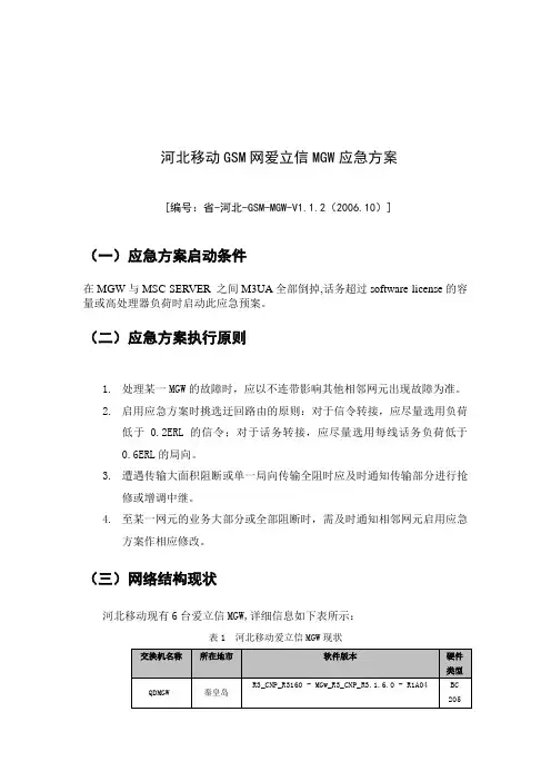
河北移动GSM网爱立信MGW应急方案[编号:省-河北-GSM-MGW-V1.1.2(2006.10)](一)应急方案启动条件在MGW与MSC SERVER 之间M3UA全部倒掉,话务超过software license的容量或高处理器负荷时启动此应急预案。
(二)应急方案执行原则1.处理某一MGW的故障时,应以不连带影响其他相邻网元出现故障为准。
2.启用应急方案时挑选迂回路由的原则:对于信令转接,应尽量选用负荷低于0.2ERL 的信令;对于话务转接,应尽量选用每线话务负荷低于0.6ERL的局向。
3.遭遇传输大面积阻断或单一局向传输全阻时应及时通知传输部分进行抢修或增调中继。
4.至某一网元的业务大部分或全部阻断时,需及时通知相邻网元启用应急方案作相应修改。
(三)网络结构现状河北移动现有6台爱立信MGW,详细信息如下表所示:表1 河北移动爱立信MGW现状图1 河北移动北部端局MSC到各方向的网络结构图(四)破坏原因及破坏结果分析突发事件对MSC的影响包括:1.MGW至某方向的话路路由全部阻断形成原因:(1)对端局故障,如对端交换机瘫痪造成;(2)传输阻断造成。
破坏结果:MSC至该方向话务阻断。
2.MGW至某方向的信令路由全部阻断形成原因:(1)对端局故障,如对端交换机瘫痪造成;(2)传输阻断造成。
破坏结果:MSC至该方向话务阻断。
3、MGW负荷过高(3)节假日期间(如春节,中秋节等)产生话务高峰;(4)重大会议、大型展览会或集会产生的话务高峰。
破坏结果:到某些方向的呼叫难以接续;负荷过高有可能引起MSC限话。
3.MSC瘫痪形成原因:(1) MSC交换机硬件故障;(2) MSC交换机软件故障;(3)通信电源故障;(4)自然灾害或者意外造成的设备损坏。
破坏结果:MSC控制下的用户话务全阻。
(五)预防保障措施1.设置各种负荷门限包括:(1)话路负荷门限:0.7ERL;(2)信令负荷门限:0.3ERL;(3) CPU负荷门限:0.7。


爱立信软交换MSC-MGW局数据标准(V1.0)版本 R42006年12月中国移动通信集团广东有限责任公司注:本标准未尽之处可先按原规定或省公司相关文件执行,待以后补充。
目录版本说明 (4)1节点配置 (4)1.1节点命名 (4)1.2配置版本(C ONFIGURATION V ERSION,CV) (4)1.3交换机网元数据 (4)2物理接口配置 (5)2.1物理端口 (5)2.2ET-MC1 (5)2.3ET-MC41和ET-C41 (5)2.4ET-M4 (8)3O & M 配置 (9)4TDM传输 (11)4.1TDM传输原则 (11)4.2D S0B UNDLE (12)4.3TDM终端组(T DM T ERM G RP) (13)4.4复用段保护(MSP) (13)5ATM 传输 (15)5.1ATM Q O S (15)5.2ATM话务描述 (15)5.3ATM反向复用(IMA) (16)5.4AAL2路径 (17)6信令 (18)6.1MTP3层(MTP3,MTP3B AND M3UA) (19)6.2基于TDM的信令 (21)6.2.1MTP Level 2 (22)6.3基于IP的信令 (24)6.3.1SCTP (24)6.4ISUP (28)6.5Q.AAL2 (28)6.5.1Q.AAL2信令点 (28)6.5.2AAL2 Routing Case (29)6.5.3AAL2接入点 (AAL2 AP) (29)6.5.4AAL2路径分配单元(AAL2 PDU) (30)6.6GCP (30)6.7MAP (30)7虚拟 MGW (VMGW) (31)8录音通知 (IM) (31)8.1基本通知音(B ASIC M ESSAGE) (31)8.2变量通知音(V ARIABLE M ESSAGE) (32)8.3通知音复合(M ESSAGE C OMPOSITION) (33)9媒体流功能 (33)10MGW铃音 (37)11网络同步 (39)12网络维护的常用流程 (39)12.1定义一个新的网络节点 (39)12.1.1定义一个新的窄带ISUP/TUP局向 (39)12.1.2定义一个新的BSC (40)12.2建立新的信令链路 (40)12.2.1建立新的局间信令链路 (40)12.2.2建立新的BSC信令链路 (40)12.3建立新的话务链路 (41)13附录 (41)版本说明该文档描述了爱立信MGW R4的配置原则和局数据标准。
MGW之软件介绍以及操作维护梁远锡爱立信的媒体网关产品M-MGW是基于面向3G及未来应用的CPP(Connectivity Packet Platform)平台, 应用于分层的WCDMA核心网络中, 完成所有连接层的业务需要.具体操作,请查看ALEX WMAS 的操作。
EMAS界面窗口有:-Software View: 用于软件备份和升级-Equipment View: 用于硬件(Subrack, Board)配置和维护-ATM View: 用于ATM承载配置和维护-SS7 View: 用于SS7配置和维护-IP View: 用于IP路由和IP承载配置和维护-Media Stream Service View: 用于媒体业务配置和维护-Device View: 用于媒体处理设备配置和维护-Virtual Media Gateway View: 用于VMGW配置和维护-TDM Termination group View: 用于TDM承载配置和维护M-MGW的操作维护涵盖了网络节点连接、性能指标监测、功能维护、安全管理及文本处理等内容。
所有的操作维护内容可以分为以下的七部分:设备管理该部分功能包括M-MGW节点的硬件平台配置和管理。
软件管理该部分功能包括M-MGW节点的软件控制和管理。
M-MGW节点支持本地及远程的软件许可、安装、升级及备份。
配置管理该部分功能包括M-MGW节点的参数设置等。
性能管理该部分功能包括M-MGW的性能指标监测、及性能统计数据的管理。
错误管理该部分功能包括M-MGW节点硬见及软件错误的检测、修复及报告。
操作维护安全性该部分功能包括操作维护的安全性管理,避免未经授权的系统接入。
操作维护的日志文件该部分功能包括M-MGW节点操作维护的日志文件管理操作维护应用该部分集中说明M-MGW网元管理器如何实现操作维护的所有应用。
一、设备管理M-MGW的设备管理功能使操作维护人员能够远程监测节点中所有的硬件模块以及当前的状态。
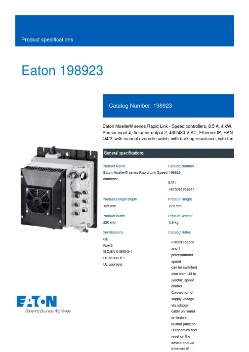
Eaton 198923Eaton Moeller® series Rapid Link - Speed controllers, 8.5 A, 4 kW, Sensor input 4, Actuator output 2, 400/480 V AC, Ethernet IP, HAN Q4/2, with manual override switch, with braking resistance, with fanGeneral specificationsEaton Moeller® series Rapid Link Speed controller1989234015081969814195 mm 270 mm 220 mm 3.8 kg CE RoHSIEC/EN 61800-5-1 UL 61800-5-1 UL approvalProduct NameCatalog NumberEANProduct Length/Depth Product Height Product Width Product Weight Certifications Catalog Notes 3 fixed speeds and 1 potentiometer speedcan be switched over from U/f to (vector) speed control Connection of supply voltage via adapter cable on round or flexible busbar junction Diagnostics and reset on the device and via Ethernet IPParameterization: drivesConnectInternal and on heat sink, temperature-controlled Fan Parameterization: FieldbusParameterization: drivesConnect mobile (App) Parameterization: KeypadKey switch position AUTOFanBraking resistanceKey switch position OFF/RESETTwo sensor inputs through M12 sockets (max. 150 mA) for quick stop and interlocked manual operationPTC thermistor monitoringInternal DC linkBreaking resistanceManual override switchKey switch position HANDSelector switch (Positions: REV - OFF - FWD)Control unitPC connection2 Actuator outputsIGBT inverterThermo-click with safe isolation4-quadrant operation possibleBrake chopper with braking resistance for dynamic braking3 fixed speedsFor actuation of motors with mechanical brake1 potentiometer speed NEMA 12IP651st and 2nd environments (according to EN 61800-3)IIISpeed controllerEtherNet/IPC2, C3: depending on the motor cable length, the connected load, and ambient conditions. External radio interference suppression filters (optional) may be necessary.C1: for conducted emissions only2000 VCenter-point earthed star network (TN-S network)AC voltagePhase-earthed AC supply systems are not permitted.Vertical15 g, Mechanical, According to IEC/EN 60068-2-27, 11 ms, Half-sinusoidal shock 11 ms, 1000 shocks per shaftResistance: According to IEC/EN 60068-2-6Resistance: 10 - 150 Hz, Oscillation frequencyResistance: 57 Hz, Amplitude transition frequency on accelerationResistance: 6 Hz, Amplitude 0.15 mmFeatures Fitted with:Functions Degree of protectionElectromagnetic compatibility Overvoltage categoryProduct categoryProtocolRadio interference classRated impulse withstand voltage (Uimp) System configuration typeMounting positionShock resistanceVibrationAbove 1000 m with 1 % performance reduction per 100 m Max. 2000 m-10 °C40 °C-40 °C70 °CIn accordance with IEC/EN 50178< 95 %, no condensation 0.8 - 8.5 A, motor, main circuit Adjustable, motor, main circuit< 10 ms, Off-delay< 10 ms, On-delay98 % (η)7.8 A3.5 mA120 %Maximum of one time every 60 seconds380 V480 V380 - 480 V (-10 %/+10 %, at 50/60 Hz)Synchronous reluctance motorsU/f controlSensorless vector control (SLV)BLDC motorsPM and LSPM motors0 Hz500 HzAt 40 °CFor 60 s every 600 s12.7 AAltitudeAmbient operating temperature - min Ambient operating temperature - max Ambient storage temperature - min Ambient storage temperature - max Climatic proofing Current limitationDelay timeEfficiencyInput current ILN at 150% overload Leakage current at ground IPE - max Mains current distortionMains switch-on frequencyMains voltage - minMains voltage - maxMains voltage toleranceOperating modeOutput frequency - minOutput frequency - maxOverload currentOverload current IL at 150% overload45 Hz66 Hz8.5 A at 150% overload (at an operating frequency of 8 kHz and an ambient air temperature of +40 °C)4 kW480 V AC, 3-phase400 V AC, 3-phase0.1 Hz (Frequency resolution, setpoint value)200 %, IH, max. starting current (High Overload), For 2 seconds every 20 seconds, Power section50/60 Hz8 kHz, 4 - 32 kHz adjustable, fPWM, Power section, Main circuitCenter-point earthed star network (TN-S network)AC voltagePhase-earthed AC supply systems are not permitted.5 HP≤ 0.6 A (max. 6 A for 120 ms), Actuator for external motor brakeAdjustable to 100 % (I/Ie), DC - Main circuit≤ 30 % (I/Ie)400/480 V AC -15 % / +10 %, Actuator for external motor brake765 VDC10 kAType 1 coordination via the power bus' feeder unit, Main circuit24 V DC (-15 %/+20 %, external via AS-Interface® plug)400/480 V AC (external brake 50/60 Hz)Ethernet IP, built inPlug type: HAN Q4/2Max. total power consumption from AS-Interface® power supply C2 ≤ 5 m, maximum motor cable length C3 ≤ 25 m, maximum motor cable length C1 ≤ 1 m, maximum motor cable lengthRated frequency - minRated frequency - maxRated operational current (Ie)Rated operational power at 380/400 V, 50 Hz, 3-phase Rated operational voltageResolutionStarting current - maxSupply frequencySwitching frequencySystem configuration type Assigned motor power at 460/480 V, 60 Hz, 3-phase Braking currentBraking torqueBraking voltageSwitch-on threshold for the braking transistorRated conditional short-circuit current (Iq)Short-circuit protection (external output circuits) Rated control voltage (Uc)Communication interfaceConnectionInterfacesCable lengthunit (30 V): 250 mANumber of slave addresses: 31 (AS-Interface®) Specification: S-7.4 (AS-Interface®)Meets the product standard's requirements.Meets the product standard's requirements.Meets the product standard's requirements.Meets the product standard's requirements.Meets the product standard's requirements.Does not apply, since the entire switchgear needs to be evaluated.Does not apply, since the entire switchgear needs to be evaluated.Meets the product standard's requirements.Does not apply, since the entire switchgear needs to be evaluated.Meets the product standard's requirements.Does not apply, since the entire switchgear needs to be evaluated.Does not apply, since the entire switchgear needs to be evaluated.Is the panel builder's responsibility.Is the panel builder's responsibility.Is the panel builder's responsibility.Is the panel builder's responsibility.10.2.2 Corrosion resistance10.2.3.1 Verification of thermal stability of enclosures 10.2.3.2 Verification of resistance of insulating materials to normal heat10.2.3.3 Resist. of insul. mat. to abnormal heat/fire by internal elect. effects10.2.4 Resistance to ultra-violet (UV) radiation 10.2.5 Lifting10.2.6 Mechanical impact10.2.7 Inscriptions10.3 Degree of protection of assemblies10.4 Clearances and creepage distances 10.5 Protection against electric shock10.6 Incorporation of switching devices and components 10.7 Internal electrical circuits and connections 10.8 Connections for external conductors 10.9.2 Power-frequency electric strength 10.9.3 Impulse withstand voltageIs the panel builder's responsibility.The panel builder is responsible for the temperature rise calculation. Eaton will provide heat dissipation data for the devices.Is the panel builder's responsibility. The specifications for the switchgear must be observed.Is the panel builder's responsibility. The specifications for the switchgear must be observed.The device meets the requirements, provided the information in the instruction leaflet (IL) is observed.Connecting drives to generator suppliesGeneration Change RA-SP to RASP5Electromagnetic compatibility (EMC)Generation change RAMO4 to RAMO5Generation change from RA-MO to RAMO 4.0Configuration to Rockwell PLC for Rapid LinkGeneration Change RASP4 to RASP5Generation change from RA-SP to RASP 4.0Rapid Link 5 - brochureDA-SW-USB Driver PC Cable DX-CBL-PC-1M5DA-SW-Driver DX-CBL-PC-3M0DA-SW-drivesConnect - InstallationshilfeDA-SW-drivesConnect - installation helpDA-SW-drivesConnectDA-SW-USB Driver DX-COM-STICK3-KITDA-SW-drivesConnect USB Driver DX-COM-PCKITMaterial handling applications - airports, warehouses and intra-logisticsProduct Range Catalog Drives Engineering-ENProduct Range Catalog Drives EngineeringDA-DC-00004508.pdfDA-DC-00003964.pdfDA-DC-00004184.pdfDA-DC-00004514.pdfeaton-bus-adapter-rapidlink-speed-controller-dimensions-003.eps eaton-bus-adapter-rapidlink-speed-controller-dimensions-005.eps eaton-bus-adapter-rapidlink-speed-controller-dimensions-004.eps eaton-bus-adapter-rapidlink-speed-controller-dimensions-002.epsETN.RASP5-8424EIP-412R101S1.edzIL034093ZU10.9.4 Testing of enclosures made of insulating material10.10 Temperature rise10.11 Short-circuit rating10.12 Electromagnetic compatibility 10.13 Mechanical function Application notes BrochuresCatalogues Certification reports DrawingseCAD model Installation instructionsEaton Corporation plc Eaton House30 Pembroke Road Dublin 4, Ireland © 2023 Eaton. All rights reserved. Eaton is a registered trademark.All other trademarks areproperty of their respectiveowners./socialmediaRapid Link 5MN040003_EN MZ040046_EN MN034004EN DA-MN-MZ040044EN ramo5_v32.dwg rasp5_v32.stpInstallation videos Manuals and user guides mCAD model。
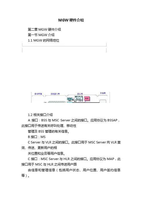
MGW硬件介绍第二章MGW硬件介绍第一节MGW介绍1.1 MGW的网络地位1.2 相关接口介绍A 接口:BSS与MSC Server之间的接口。
应用协议为BSSAP,此接口用于传送有关呼叫处理、移动性管理及BSS 管理的有关信息。
B 接口:MSC Server与VLR之间的接口。
此接口用于MSC Server向VLR 查询、传送、更新用户的相关位置和业务等用户信息。
C 接口:MSC Server与HLR之间的接口。
应用协议为MAP,此接口用于MSC与HLR之间传送用户路由信息和管理信息(包括用户状态、用户位置、用户签约信息等)。
D 接口:指VLR 与HLR 之间的接口。
应用协议为MAP,此接口用于在HLR 与VLR 之间交换有关移动台位置信息及用户管理信息。
E 接口:MSC Server与MSC Server之间接口。
应用协议为MAP,主要用于局间切换。
G 接口:VLR 与VLR 之间的接口,应用协议为MAP,主要用于当前VLR 向先前的VLR 索取IMSI 和鉴权集。
Iu-CS 接口:RNC与MSC Server之间接口。
应用协议为RANAP,其功能与A接口类似。
Mc 接口:MSC Server 与MGW接口。
采用H.248 协议,主要功能是MSC Server在呼叫处理过程中控制MGW 中各类传输方式(IP/ATM/TDM)的静态及动态资源的能力(包括终端属性、终端连接交换关系及其承载的媒体流);还提供了独立于呼叫的MGW 状态维护与管理能力。
Nc 接口:是指不同的MSC Server之间的接口。
应用协议为BICC,为电路域业务提供独立于用户面承载技术及控制面信令传输技术的局间呼叫控制能力,实现不同网络之间的互通。
Nb接口:是指不同的MGW之间的接口。
当采用ATM或者IP 承载方式时,应用层协议为NbUP;当采用TDM 承载方式时,无应用层的适配协议。
该接口完成承载的控制与传输功能;支持业务数据的多种传输方式。
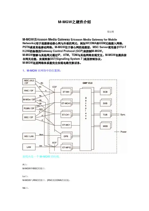
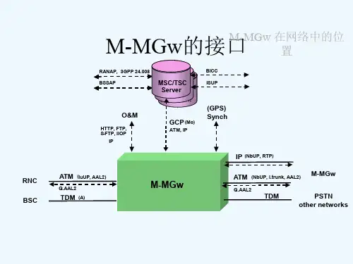
M-MGW之硬件介绍梁远锡M-MGW(Ericsson Media Gateway Ericsson Media Gateway for Mobile Networks)用于连接移动核心网与外部的网元,例如WCDMA和GSM无线接入网络,PSTN或者其他移动网络。
M-MGW位于核心网的连接层,MSC Server使用基于ITU-T H.248的标准的Gateway Control Protocol (GCP)来控制M-MGW。
M-MGW能够与其他网元通过IP,ATM,TDM与其他网络实现交互。
M-MGW也提供信令网关功能,实现转换SS7(Signalling System 7 )底层控制协议。
M-MGW这层网络体系能完全实现电路交换话务。
1、M-MGW在网络中的位置图:虚线内是一个M-MGW的结构。
A口:M-MGW和BSC的接口。
Lu口:M-MGW与RNC的接口。
(RNC是CDMA的设备)。
Nb口:M-MGW与M-MGW之间的接口。
Mc口:M-MGW和MSC Server之间的接口。
MomM-MGW与核心网操作维护中心(CN-OSS )之间的接口。
板)。
MSB configuration 2是指M-MGw Module的12-15板是MSB板。
3、机架结构:正面从下往上分别是1A,1B,1C,1D,背面从上往下分别是2D,2C,2B,2A(如果有的话)。
主框(CPM)都在1B的位置。
我们称这个框为“subrack1”(子框1)(只有一个Central Processor Module的是BC 3050/51配置);CPM框上面的第一个M-MGw Module 1(1C的位置),我们称为subrack2;(只有一个M-MGw Module的是BC 3001和BC 3002)CPM框下面的一个M-MGw Module 2(1C的位置),我们称为subrack3;要是超过两个M-MGw Module,第三个M-MGw Module 3是位于背面的最上面(2D的位置),我们称为subrack4;第四个M-MGw Module 4,是位于背面的第二个机框(2C的位置),我们称为subrack5;第五个M-MGw Module 5,是位于机框正面最上面的机框(1D的位置),我们称为subrack6。


爱立信设备讲解爱立信设备的核心部件包括基站、传输设备、终端设备等。
基站是通讯网络的重要组成部分,它负责接收和发送无线信号,并将其转换为有线信号传输到核心网。
传输设备用于将信号传输到目标地点,通常采用光纤或微波等技术。
终端设备包括手机、无线网卡、路由器等,它们用于接收和发送信号。
爱立信设备在通信网络中具有重要的作用,它们可以实现高速传输和稳定连接,为用户提供优质的通信服务。
同时,爱立信设备采用先进的技术和设计,具有较低的功耗和较高的可靠性,可以满足各种复杂环境下的通讯需求。
总的来说,爱立信设备是一种先进的通讯设备,具有高性能和可靠性。
它们广泛应用于各种通信网络中,为用户提供高速传输、低功耗和稳定连接的通讯服务。
随着通讯技术的不断发展,爱立信设备将继续发挥重要作用,推动通讯网络的进一步发展和升级。
很高兴能为你介绍更多关于爱立信设备的信息。
爱立信作为一家领先的通讯技术公司,其设备在通信领域扮演着至关重要的角色。
爱立信设备的应用范围非常广泛,包括移动通信网络、固定通信网络、物联网、5G网络等。
首先,让我们来看看在移动通信领域中,爱立信设备的应用。
在移动通信网络中,爱立信的基站设备扮演着至关重要的角色。
这些基站设备通过无线信号的接收和发送,实现了用户手机和核心网之间的连接。
基站设备的关键组成部分包括天线系统、收发信机、传输系统等。
这些设备通过高效的信号处理和传输技术,为用户提供稳定快速的通信服务。
另外,爱立信设备在固定通信网络中也有着重要的应用。
固定通信网络包括有线电话、宽带接入等,而爱立信的设备可以实现这些网络中的信号传输、接收和处理等功能。
在固定通信领域,爱立信设备可以提供高速、稳定的信号传输,为用户提供优质的通信服务。
除了移动和固定通信网络,爱立信设备也在物联网中发挥着重要作用。
物联网是指各种设备和物品之间能够相互连接、通信并实现智能化控制的网络。
在物联网中,爱立信的设备可以实现对各种智能设备的连接和控制,使得这些设备能够相互通信,实现智能化的功能,并在各种场景中提升效率。
技术总结目录:1、 现网结构2、 软交换简述3、 软交换网络结构4、 Media Gateway 介绍1、 Media Gateway 功能2、 Media Gateway 硬件3、 Media Gateway 各单板介绍4、 Media Gateway 的硬件配置5、 Media Gateway 的管理与操作1、 现网结构:网络结构大体上分为无线接入网(RN )、核心网(CN )和操作维护子系统(OSS )三部分。
如图所示:BSCRBSMSCBSCRBS MSCHLRHLRVLRAUCMSCHLRBSCRBSBSCRBSRNCNRN无线接入网核心网无线接入网A BisA A BisA Bis A BisA图1.1而交换系统是核心网的一部分,包括MSC (移动交换中心)及存储用户数据和移动管理信息的数据库。
MSC 的功能是处理和协调GSM 系统用户的通信接续,传递用户数据或信令。
MSC 通过A 接口与若干个BSC 相连,MSC 还连接着VLR (拜访位置寄存器)、HLR (归属位置寄存器)和AUC (鉴权中心)等媒体网关媒体网关分组核心网电路交换网分组网接入网电路交换网分组网接入网软交换业务软交换在NGN 网络中的位置BSCRBSBSCRBSAA bisA bisGSM RANUmMSC ServerPSTNPLMNMSC ServerHLRMcApplication Server Application ServerServiceServers 相连接。
现行网络的语音交换系统都是以程控电话交换机为基础的电路交换系统,其特点是建立链路快,链路一旦建立就一直连通,不论中间停顿与否,电路利用率低。
而现在的发展方向为以数据包分组为基础的分组交换,用分组数据包承载话音数据(如V oIP ),形成虚链路连接,实现了线路动态统计复用,提高线路利用率,而且能灵活地满足各种业务要求。
软交换就是在这样一种背景中 发展起来的。
MGW新建局调测手册v1.0MGW新建局调测手册v1.0 (1)一、MGW理论知识介绍 (2)二、调测流程 (2)1.前期准备 (2)2.加电 (4)3.本调 (5)4.联调 (11)5.测试 (16)6.割接 (17)7.故障分析案例 (17)三、附录: (18)1.moshell常用指令描述。
(18)2.moshell通配符介绍 (19)3.moshell快捷键操作: (20)一、MGW理论知识介绍(略)二、调测流程1.前期准备✧工具准备软件准备:进行MGW的调测之前,需要安装一些软件,主要包括以下内容。
◆JAVA插件,用于打开MGW的EMAS软件。
对版本要求比较高,建议安装java_1.3.9版本。
假如电脑里原来安装过JAVA插件,有可能打不开EMAS,建议删除重新安装正确的版本。
◆FTP服务器软件(通用的软件,网上有很多,目前我们常用的是CesarFTP),用于将liscense 文件上传到MGW。
◆Winfiol7.0或超级终端,用于MGW的串口连接时的操作,winfiol的优势是可以方便的保存LOG文件。
●WINFIOL设置;Protocal:RS232(serial port)Setup:Baud rate:9600Flow control:noneParity:noneData bits:8 bitsStop bits:1 bitsControl siginals:不选Target:cpp(ncli)(只有winfiol 7.0才有该选择项)●连接到SERVER时设置是tcp/ip(telnet),port :23,ansi,apg40●连接到浪潮时设置是tcp/ip(telnet),PORTNb:18000,dtterm,apg40●超级终端设置:只需还原为默认值就可以了。
◆Cywin、moshell,这两个软件是配合使用的,安装过程比较复杂,一次安装成功率据说和人品很有关系,在此不赘述。
MGW原理精讲一、简介众所周知,软交换将原来的MSC节点分裂成MSC-S和MGW两个节点,使网络结构变得更加复杂。
从运维角度来看,无疑增加了成本。
从网络安全角度来看,增加节点等于增加故障隐患。
但我们为什么还要使用软交换呢?第一,软交换技术实现了包交换,大大提高了网络容量及利用率。
第二,软交换技术实现了呼叫控制和承载控制的分离,与目前网络的垂直分层结构发展趋势是一致的,更有利于新业务的推出以及分层演进。
那MGW又位于网络中的什么位置呢?以图1-1和图1-2为例图1-1图1-2图1-1较乱,看了别晕,其实是爱立信软交换(R4版本)针对现网向3G过渡的解决方案。
强调一点,爱立信软交换R4版本只实现了CS域的承载与控制分离,PS域并没有变动。
此图中我们只关注红圈内即核心网各节点间接口。
不难发现,相对于原有2G网络,图中增加了MSC-S与MSC-S之间的Nc接口,MSC-S与MGW之间的Mc接口以及MGW与MGW之间的Nb接口。
对照图1-2,相对应的出现了三种新的协议,分别是Nc接口的BICC协议,Mc接口的H.248(GCP)协议以及Nb接口的IPBCP协议(根据移动现网情况,本文对ATM承载不做具体介绍)。
其中BICC协议并非本文讨论内容,下面将对GCP及IPBCP做简要介绍。
GCP协议GCP协议全称叫做Gateway Control Protocol,从名字就可以看出,GCP协议的主要实现的就是MSC-S对MGW上的资源管理功能。
所以GCP消息叫做COMMAND,凸显的就是MSC-S的MASTER与MGW的SLA VE之间的关系。
GCP消息是有方向性的,而且大部分是由MSC-S发送给MGW的,并且总是成对出现,即一方发送消息后,另一方需要reply。
GCP消息是宽带信令消息,不能用原来的窄带MTP来传输,现网采用的是SIGTRAN来实现可靠传输。
GCP消息共分为7种,分别是ADD、SUBTRACT、MOVE、MODIFY、AUDITV ALUE、SERVICE CHANGE以及NOTIFY。
MGW硬件基础知识介绍(R4)1、MGW(R4)的基本知识⑴、MGW(R4)硬件配置有BC 3001, 3002, 3003, 3004, 3024, 3050 and 3051这几种类型.山东现在常见的配置为BC3003,BC3004,BC3024。
The M—MGw 产品包为Generic M-MGw Package (GMP) Vx。
yBase configuration. 且软件版本M—MGw Rz。
例如:我们现在使用R4的MGW设备为GMP V3。
0BC 3024R4.1。
2。
0,其中GMP V3.0指Generic M—MGw Package,BC 3024指硬件配置,R4。
1。
2.0指软件版本。
下图为MGW的容量对比:『GMP V2.0』『GMP V2。
1』『GMP V3。
0』⑵、MGW:与MSC Server、GMSC Server配合完成核心网络资源的配置(即承载信道的控制)。
同时完成回声消除、(多媒体数字)信号的编解码以及通知音的播放等功能。
SG:完成信令转换工作.即完成SS7的传送层MTP与SIGTRAN的传送层SCTP/IP之间的转换,同时实现在SS7和IP 之间MAP_E和MAP_G的信令互通。
高层信令MAP、CAP 不进行转换。
MGW相对于MSC Server,完成承载功能的时候,永远是处于Slave地位.MGW相对于其他端局,完成信令转换功能的时候,是处于Peer关系。
⑶、架间连线:多个机框间以星型拓扑连接,每块SCB/SXB 4根ISL,620 Mbps / 板,每个ISL 310兆,ISL 1+1 或N+1冗余。
⑷、The Virtual Media Gateway concept·一个MGW可以受多个MSC—S控制,ITU—T H。
248.1,GCP version2·灵活的容量利用,良好的网络冗余·一个MSC服务器最多控制256个MGW·一个MGW最多支持32个虚拟MGW2、MGW特点介绍⑴、爱立信WCDMA系统移动媒体网关M—Mgw R4功能和特性包括:—虚拟媒体网关。
MGW主要功能模块实现介绍1.MGW系统结构1.1.网元1.1.1.硬件结构爱立信MGW是基于CPP硬件平台构建而成的,现网有两种硬件类型:G50-G51为GMP V2.0 BC206平台(VOIP改造完成之后将升级为GMP V2.1 BC216平台),G54-G86为GMP V3.0 BC3004平台。
对于BC206的平台,有五个机框组成:对于BC3004平台,有三个机框组成:1.1.2.软件结构爱立信MGW的软件功能由LICENSE来控制,LICENSE分为两类:feature和capacity。
前者是一个开关类型的参数,标识了MGW是否具有某一种功能,而后者是一个容量类型的参数,标识了MGW的接续能力有多大。
以现网VOIP以及2/3G融合的端局MGW6601为例,feature包含了TDM Cross Connection、IP Transport、UMTS IU interface、GSM A interface、SS7 over IP、compress speech on nb、fax service、MBAC这些;而capacity包含了CSD 数据业务处理能力和承载话务量两类。
1.1.3.网元备份爱立信MGW均采用了双连的网络拓扑结构,保证一个MGW发生故障退服时,在容量范围之内,另外一个MGW可以承载所有的业务。
如果出现MGW未完全退服但又无法进行话务承载的情况,机房现场也可以通过人机命令的方式人工关闭MGW而转移业务。
1.2.机框1.2.1.BC206 – Main Subrack由板卡SCB(交换板卡)、GPB(通用功能板卡)、TUB(时钟板卡)、SXB(辅助交换板卡)组成,完成MGW的核心控制功能。
如果该机框退服(一般只可能是电源问题,但电源也有两路主备用工作),则该MGW会宕机,没有备份机框。
此时只能通过两个MGW的网络层冗余进行保护。
1.2.2.BC206 – ATM Extension Subrack由板卡SCB(交换板卡)、GPB(通用功能板卡)、ET-M4(ATM接口板卡)、ET-MC41(TDM 155M接口板卡)、ET-MC1(TDM 2M接口板卡)、SXB(辅助交换板卡)组成,主要完成与外部网元的ATM承载功能。