DOP触摸屏培训资料
- 格式:ppt
- 大小:5.84 MB
- 文档页数:46
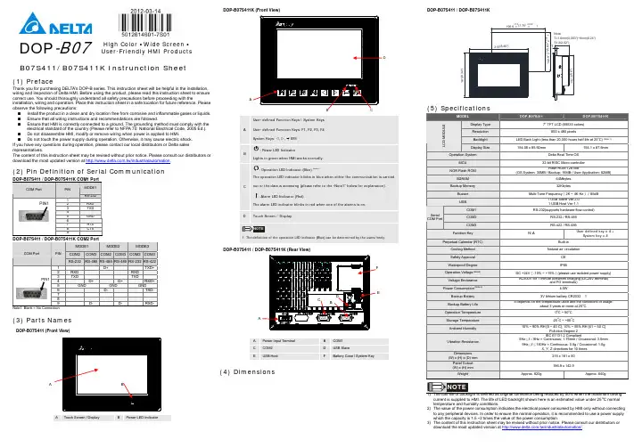


Preface Thank you for purchasing DELTA’s DOP-B series. This quick start will be helpful in the installation, wiring and inspection of Delta HMI. Before using the product, please read this quick start to ensure correct use. You should thoroughly understand all safety precautions before proceeding with the installation, wiring and operation. Place this quick start in a safe location for future reference. Please observe the following precautions:⏹Install the product in a clean and dry location free from corrosive and inflammable gases orliquids.⏹Ensure that all wiring instructions and recommendations are followed.⏹Ensure that HMI is correctly connected to a ground. The grounding method must comply withthe electrical standard of the country (Please refer to NFPA 70: National Electrical Code, 2005 Ed.).⏹Do not modify or remove wiring when power is applied to HMI.⏹Do not touch the power supply during operation. Otherwise, it may cause electric shock.⏹For the information of HMI software operation, and software installation, please refer to theHMI software manual.If you have any questions during operation, please contact our local distributors or Delta sales representative.The content of this quick start may be revised without prior notice. Please consult our distributors or download the most updated version at /industrialautomation.Safety PrecautionsCarefully note and observe the following safety precautions when receiving, inspecting, installing, operating, maintaining and troubleshooting. The following words, DANGER, WARNING and STOP are used to mark safety precautions when using the Delta’s HMI product. Failure to observe these precautions may void the warranty!InstallationWiringCall 1(800)985-6929 for SalesOperationD o not modify wiring during operation. Otherwise it may result in electric shockor personal injury.N ever use a hard or pointed object to hit or strike the screen as doing this may damage the screen and let the screen has not respond at all, and then cause HMIto work abnormally.Maintenance and InspectionD o not touch any internal or exposed parts of the HMI as electrical shock mayresult.Do not remove operation panel while power is on. Otherwise electrical shock may result.W ait at least 10 minutes after power has been removed before touching any HMI terminals or performing any wiring and/or inspection as an electrical charge maystill remain in the HMI with hazardous voltages even after power has beenremoved.T urn the power off before changing backup battery and check system settings after finishing change. (all data will be cleared after changing battery).B e sure the ventilation holes are not obstructed during operation. Otherwisemalfunction may result due to bad ventilation or overheating troubles.Wiring MethodCommunication WiringInstallation and Storage ConditionsThe product should be kept in the shipping carton before installation. In order to retain the warranty coverage, the HMI should be stored properly when it is not to be used for an extended period of time. Some storage suggestions are:⏹Store in a clean and dry location free from direct sunlight.⏹Store within an ambient temperature range of -20°C to +60°C (-4°F to 140°F).*********************** Call 1(800)985-6929 for Sales⏹Store within a relative humidity range of 10% to 90% and non-condensing.⏹Do not store the HMI in a place subjected to corrosive gases and liquids.⏹Correctly packaged and placed on a solid and durable surface.⏹Do not mount the HMI adjacent to heat-radiating elements or in direct sunlight.⏹Do not mount the HMI in a location subjected to corrosive gases, liquids, or airborne dust ormetallic particles.⏹Do not mount the HMI in a location where temperatures and humidity will exceedspecification.⏹Do not mount the HMI in a location where vibration and shock will exceed specification.⏹Do not mount the HMI in a location where it will be subjected to high levels ofelectromagnetic radiation.InstallationInstallation Notes⏹Improper installation will result in malfunction and greatly reduce the life of the HMI. Be sureto follow the guidelines in this quick start when installing the HMI.⏹In order to ensure the HMI being well ventilated, make sure that the ventilation holes are notobstructed and must provide sufficient free space around HMI.⏹To ensure the panel is well protected, be sure to install a waterproof gasket into HMI.⏹For use on a flat surface of a Type 4X "Indoor Use Only" enclosure or equivalent.⏹The allowable thickness of the panel for mounting should be less than 5 mm.Installation Method:Step 1:Ensure to put waterproof gasket into HMI and then insert the HMI into the panel cutout. Step 2:Ensure to insert fasteners into the HMI’s insertion slots and turn the screw till screwstouch panel cutout.Step 3:Turn the screw with less than torque 0.7N.M toavoid damage to plastic box.Step 4:Keep at least 60mm distance from rear of HMIproduct to the wall, installation surface or theother controllers for heat dissipation.Call 1(800)985-6929 for Sales*********************** Call 1(800)985-6929 for Sales***********************WiringPlease observe the following wiring notes while performing wiring.Wiring Notes⏹To prevent electric shock, do not change wiring when the power is connected and has not been turned off. ⏹Because there is no power switch on the HMI, ensure that an interrupter switch is attached on its power cable. ⏹ Please use shielded twisted-pair cables for wiring.Recommended wiring is in the table below: Wire Gauge (AWG)Stripped length Torque Solid 28 ~ 127 ~ 8 mm 5 kg-cm (4.3 lb-in) Stranded30 ~ 12 7 ~ 8 mm 5 kg-cm (4.3 lb-in) Be sure to perform wiring by referring to the following figure (power supply connector).Basic InspectionContentGeneral Inspection ⏹ Periodically inspect the screws of the connection between the HMI anddevice. Tighten screws as necessary as they may loosen due to vibrationand varying temperatures.⏹ Ensure that oil, water, metallic particles or any foreign objects do not fall inside the HMI, control panel or ventilation slots and holes. As these willcause damage.⏹ Ensure the correct installation and the control panel. It should be freefrom airborne dust, harmful gases or liquids.Inspection before operation (power is not applied) ⏹ Ensure that all wiring terminals are correctly insulated.⏹ Ensure that all wiring is correct or damage and or malfunction may result.⏹ Visually check to ensure that there are not any unused screws, metalstrips, any conductive or inflammable materials inside HMI.⏹ Ensure to lower electromagnetic interference when devices are influencedby it.⏹ Ensure that the external applied voltage to HMI is correct and matched tothe controller.Inspection before operation (power is applied)⏹ Check if power LED lights.⏹ Check if the communication among devices is normal.⏹ Please contact our local distributors or Delta sales representative if thereare any abnormal conditions. Call 1(800)985-6929 for Sales ***********************Call 1(800)985-6929 for Sales ***********************Pin Definition of Serial CommunicationDOP-B07S(E)415/DOP-B07PS415 / DOP-B08S(E)515 / DOP-B10S(E)615 SeriesCOM1 Port (Supports Flow Control)ContactCOM Port PIN RS-23212 RXD3 TXD45 GND67 RTS8 CTS9 PIN 1Note: Blank = No Connection.COM2 Port (Supports Flow Control)MODE1 MODE2 MODE3 COM PortPIN RS-232 RS-422 RS-485 1 TXD+ D+ 2 RXD 3 TXD 4 RXD+ 5 GND GND GND 6 TXD- D-7 RTS8 CTS9 RXD-PIN1Note1: Blank = No Connection.Note2: When COM2 port is used for RS-232 flow control, i.e. RTS and CTS signals are used for flow control,COM3 port will become incapable of being used.Note3: When COM2 port is used for RS-422 flow control, please refer to the following COM3 Port signalstable for pin assignments. The signals, RTS+, CTS+, RTS- and CTS- shown in brackets are the signals used for flow control. COM3 PortMODE1 MODE2 MODE3 COM PortPIN RS-232 RS-422 RS-485 1 TXD+(RTS+) D+ 2 RXD 3 TXD 4 RXD+(CTS+) 5 GND GND GND 6 TXD-(RTS-) D-789 RXD-(CTS-)PIN1 Note1: Blank = No Connection.Note2: When COM2 port is used for RS-422 flow control, please refer to the COM3 Port signals table abovefor pin assignments. The signals, RTS+, CTS+, RTS- and CTS- shown in brackets are the signals used for flow control.Call 1(800)985-6929 for Sales ***********************Call 1(800)985-6929 for Sales ***********************Ethernet Interface (LAN)Contact Ethernet Interface (LAN)PIN Ethernet 1 TX+ 2 TX-3 RX+456 RX-78 Note: Blank = No Connection.DOP-B05 / DOP-B07S(E)515 / DOP-B07PS515 Series COM1 Port (Supports Flow Control)Contact COM PortPIN RS-232 1 2 RXD 3 TXD45 GND67 RTS8 CTS9 PIN1 Note: Blank = No Connection.COM2 and COM3 PortMODE1 MODE2 MODE3 COM2COM3COM2 COM3COM2COM3COM PortPIN RS-232RS-485RS-485RS-485RS-232RS-4221 D+ TXD+2 RXD RXD 3 TXD TXD 4 D+ D+ RXD+5 GND GND GND 6 D- TXD-789 D- D- RXD-PIN1Note1: Blank = No Connection.Note2: B05 / B07S(E)515/ B07PS515 series models do not support RS-422 flow control function.Call 1(800)985-6929 for Sales ***********************Call 1(800)985-6929 for Sales ***********************Parts NamesDOP-B05S100 / DOP-B05S101 (Front View)BAPower LED Indicator (Lights in green when HMI works normally.) B Touch Screen / DisplayDOP-B05S100 / DOP-B05S101 (Rear View)Call 1(800)985-6929 for Sales ***********************Call 1(800)985-6929 for Sales ***********************AA Power LED Indicator (Lights in green when HMI works normally.)B Touch Screen / DisplayDOP-B07S(E)515 / DOP-B07PS515 (Rear View)A*********************** Call 1(800)985-6929 for SalesC: Power LED IndicatorLights in green when HMI works normally.: Operation LED Indicator (Blue)The operation LED indicator blinks in blue when either the communication is carried out or the data is accessing (please refer to the “Note1” below for explanation).: Alarm LED Indicator (Red)The alarm LED indicator blinks in red when one of the alarms is on.***********************Call 1(800)985-6929 for SalesDOP-B07S(E)415/ DOP-B07PS415 (Rear View)A Power Input TerminalBCOM3(It is provided with two LED indicators to indicate that HMI is in Read or Write status during the communication process.)C COM2(It is provided with two LED indicators to indicate that HMI is in Read or Write status during the communication process.) D COM1 E USB ClientF Ethernet Interface (LAN)G USB HostH Audio Output InterfaceI Memory Card Slot / Battery CoverCall 1(800)985-6929 for Sales ***********************: Power LED IndicatorLights in green when HMI works normally.: Operation LED Indicator (Blue)The operation LED indicator blinks in blue when either the communication is carried out or the data is accessing (please refer to the “Note1” below for explanation).: Alarm LED Indicator (Red)The alarm LED indicator blinks in red when one of the alarms is on.A Power Input TerminalB COM3(It is provided with two LED indicators to indicate that HMI is in Read or Write status during the communication process.)C COM2(It is provided with two LED indicators to indicate that HMI is in Read or Write status during the communication process.)D COM1E USB ClientF Ethernet Interface (LAN)G USB HostH Audio Output InterfaceI Memory Card Slot / Battery Cover: Power LED IndicatorLights in green when HMI works normally.: Operation LED Indicator (Blue)The operation LED indicator blinks in blue when either the communication is carried out or the data is accessing (please refer to the “Note1” below for explanation).: Alarm LED Indicator (Red)The alarm LED indicator blinks in red when one of the alarms is on.A Power Input TerminalB COM2(It is provided with two LED indicators to indicate that HMI is in Read or Write status during the communication process.)C COM3(It is provided with two LED indicators to indicate that HMI is in Read or Write status during the communication process.)D COM1E USB ClientF Ethernet Interface (LAN)G Memory Card Slot / Battery CoverH USB HostI Audio Output InterfaceJ System KeyPanel Cut-outDOP-B05S100 / DOP-B05S101+1.0+0.04"Note:T=1.6mm(0.063")~Units: mm (inches)DOP-B07S(E)415 / DOP-B07PS415+1.0Note:T=1.6mm(0.063")~6mm(0.24")+0.04"Units: mm (inches)Call 1(800)985-6929 for Sales ***********************Note:T=1.6mm(0.063")~+0.04"Units: mm (inches)DOP-B08S(E)515Units: mm (inches)Note:T=1.6mm(0.063")~6mm(0.24")+1.0+0.04"Units: mm (inches)SpecificationsDisplay Type 5.6” TFT LCD (65536 colors) 7” Widescreen TFT LCD(65536 colors)Resolution 320 x 234 pixels800 x 480 pixelsBacklight LED Back Light (less than 20,000 hours half-life at 25C) (Note 1)L C D M O D U L EDisplay Size 113.28 x 84.70mm152.4 x 91.44mmOperation System Delta Real Time OS MCU32-bit RISC Micro-controllerNOR Flash ROMFlash ROM 4 MB(OS System: 2MB / User Application: 2MB)Flash ROM 8MB(OS System: 2MB / User Application: 6MB)Flash ROM 128 MB (OS System: 30MB / Backup: 16MB / UserApplication: 82MB) SDRAM 8Mbytes16Mbytes64Mbytes Backup Memory 128Kbytes16MbytesBuzzer Multi-Tone Frequency (2K ~ 4K Hz )/85dBSound EffectOutput AUXN/AN/AN/AStereo output N/AIEEE 802.3, IEEE802.3uEthernet InterfaceN/AN/AN/A10/100 Mbps auto-sensing (has built-in isolated power circuit (Note3)) N/A Memory CardN/AN/ASD Card (supports SDHC)USB 1 USB Host (Note 2)Ver 1.1 / 1 USBSlave Ver 1.11 USB Host (Note 2) Ver 2.0 / 1 USB Slave Ver 1.1COM1RS-232 (supports hardware flow control)COM2RS-232/RS-485RS-232/RS-422/RS-485 RS-232/RS-422/RS-485 (has built-in isolated power circuit (Note 3))RS-232/RS-422/RS-485Serial COM PortCOM3 RS-422/RS-485RS-232/RS-422/RS-485 RS-232/RS-422/RS-485(has built-inisolated powercircuit (Note 3))RS-232/RS-422/RS-485 Function Key N/A Perpetual Calendar (RTC)Built-inCooling Method Natural air circulation Safety Approval CE /UL (Note 4) /KCC (Note 4)Waterproof DegreeIP65/NEMA4Operation Voltage (Note 5) DC +24V (-10% ~ +15%)(please use isolated power supply) DC +24V (-10% ~+15%)(please use isolated powersupply) DC +24V (-10% ~+15%) (has built-in isolated power circuit (Note 3))DC +24V (-10% ~ +15%)(please use isolated powersupply)Voltage Endurance AC500V for 1 minute (between charging (DC24V terminal) and FG terminals)Power Consumption(Note 5)3.0W5W7.5W5WBackup Battery 3V lithium battery CR2032 x 1Backup BatteryLife It depends on the temperature used and the conditions of usage,about 3 years or more at 25C.Operation Temp. 0o C ~ 50oC Storage Temp. -20o C ~ +60oCAmbient Humidity 10% ~ 90% RH [0 ~ 40C], 10% ~ 55% RH [41 ~ 50C]Pollution Degree 2 Vibration Resistance IEC 61131-2 Compliant5Hz ≦f <9Hz = Continuous: 1.75mm / Occasional: 3.5mm 9Hz ≦f ≦150Hz = Continuous: 0.5g / Occasional: 1.0gX, Y, Z directions for 10 timesDimensions (W) x (H) x (D)mm184 x 144 x 50 215 x 161 x 50 Panel Cutout (W) x (H) mm172.4 x 132.4 196.9 x 142.9 WeightApprox.670gApprox.970gdriving current is supplied to HMI. The life of LED backlight shown here is an estimated value under 25C normal temperature and humidity conditions. 2) USB Host port can provide up to 5V/ 500mA of power.3) The withstand voltage of the isolated power circuit is 1500V peak for 1 minute.4) Some models are in the process of application to UL and KCC certification. For more information, please consult our distributors.5)The value of the power consumption indicates the electrical power consumed by HMI only without connecting to any peripheral devices. In order to ensure the normal operation, it is recommended to use a power supply which the capacity is 1.5 ~2 times the value of the power consumption.6) Users can download the DOPSoft software, the program editor of Delta HMI product and the user manual via the following link: /industrialautomation/.7) The content of this quick start may be revised without prior notice. Please consult our distributors or download the most updated version at /industrialautomation/.Display Type 7” TFT LCD (65536 colors) 8” TFT LCD (65536 colors) 10.1” Widescreen TFT LCD(65536 colors)Resolution 800 x 600 pixels800 x 600 pixels1024 x 600 pixelsBacklight LED Back Light (less than 10,000 hours half-life at 25C) (Note 1) L C D M O D U L EDisplay Size 141 x 105.75mm162 x 121.5mm 226 x 128.7mmOperation System Delta Real Time OS MCU 32-bit RISC Micro-controllerNOR Flash ROMFlash ROM 128 MB(OS System: 30MB / Backup: 16MB / User Application: 82MB)SDRAM 64Mbytes Backup Memory 16MbytesBuzzer Multi-Tone Frequency (2K ~ 4K Hz )/85dBSound EffectOutput AUXN/AStereo output N/AN/AStereo output N/AStereo output IEEE 802.3, IEEE 802.3u IEEE 802.3, IEEE 802.3u IEEE 802.3, IEEE 802.3u Ethernet InterfaceN/A 10/100 Mbps auto-sensin g (has built-in isolated power circuit (Note 3))N/A N/A 10/100 Mbps auto-sensing(has built-in isolated power circuit (Note 3))N/A10/100 Mbps auto-sensing (has built-in isolated power circuit (Note 3))Memory CardSD Card (supports SDHC)USB 1 USB Host (Note 2) Ver 2.0 / 1 USB Slave Ver 1.1 COM1RS-232 (supports hardware flow control)COM2RS-232/RS-485 RS-232 / RS-485(has built-in isolated powercircuit (Note 3))RS-232/RS-485RS-232/RS-422/RS-485RS-232 / RS-422 / RS-485 (has built-in isolated power circuit(Note 3)) RS-232/RS-422/RS-485RS-232 / RS-422 / RS-485 (has built-in isolated power circuit(Note 3)) Serial COM PortCOM3RS-422/RS-485 RS-422 / RS-485(has built-in isolated power circuit (Note 3))RS-422/RS-485RS-232/RS-422/RS-485RS-232 / RS-422 / RS-485 (has built-in isolated power circuit(Note 3))RS-232/RS-422/RS-485RS-232 / RS-422 / RS-485 (has built-in isolated power circuit(Note 3))Function Key N/A Perpetual Calendar (RTC) Built-inSafety Approval CE /UL (Note 4) /KCC (Note 4)Waterproof DegreeIP65/NEMA4OperationVoltage (Note 5)DC +24V (-10% ~ +15%) (please use isolated power supply) DC +24V (-10% ~ +15%) (has built-in isolated power circuit (Note 3))DC +24V (-10% ~ +15%) (pleaseuseisolatedpower supply)DC +24V (-10% ~ +15%) (please use isolated power supply) DC +24V (-10% ~ +15%) (has built-in isolated power circuit (Note 3)) DC +24V (-10% ~ +15%) (has built-in isolated power circuit (Note 3)) Voltage Endurance AC500V for 1 minute (between charging (DC24V terminal) and FG terminals)Power Consumption(Note 5)7.68W5.2W7.8W12WBackup Battery 3V lithium battery CR2032 x 1Backup BatteryLife It depends on the temperature used and the conditions of usage, about 3 years or more at25C.Operation Temp. 0o C ~ 50oC Storage Temp. -20o C ~ +60oCAmbient Humidity 10% ~ 90% RH [0 ~ 40C], 10% ~ 55% RH [41 ~ 50C]Pollution Degree 2 Vibration Resistance IEC 61131-2 Compliant5Hz ≦f <9Hz = Continuous: 1.75mm / Occasional: 3.5mm 9Hz ≦f ≦150Hz = Continuous: 0.5g / Occasional: 1.0gX, Y, Z directions for 10 times Dimensions (W) x (H) x (D)mm184 x 144 x 50 227.1 x 174.1 x 61 272 x 200 x 61 Panel Cutout (W) x (H) mm172.4 x 132.4 219.4 X 166.5 261.3 X 189.3 WeightApprox.800gApprox.1226gApprox.1520gdriving current is supplied to HMI. The life of LED backlight shown here is an estimated value under 25C normal temperature and humidity conditions. 2) USB Host port can provide up to 5V/ 500mA of power.3) The withstand voltage of the isolated power circuit is 1500V peak for 1 minute.4) Some models are in the process of application to UL and KCC certification. For more information, please consult our distributors.5)The value of the power consumption indicates the electrical power consumed by HMI only without connecting to any peripheral devices. In order to ensure the normal operation, it is recommended to use a power supply which the capacity is 1.5 ~2 times the value of the power consumption.6) Users can download the DOPSoft software, the program editor of Delta HMI product and the user manual via the following link: /industrialautomation/.7)The content of this quick start may be revised without prior notice. Please consult our distributors or download the most updated version at /industrialautomation/.Önsöz DELTA’nın DOP-B serisi operatör panellerini seçtiğiniz için teşekkürler. Bu bilgi dökümanı Delta HMI kurulum, bağlantı, bakım ve kontrolünde kullanıcıya yardımcı olacaktır. Doğru kullanım için ürünü kullanmadan önce bu dökümanı mutlaka okuyunuz. Kurulum, bağlantı ve çalışma yapmadan öncegüvenlik uyarılarını tamamen anladığınızdan emin olunuz. Bu dökümanı daha sonra da kullanmak için iyi muhafaza ediniz. Lütfen aşağıdaki güvenlik uyarılarına dikkat ediniz:⏹Ürünün kurulumunu yanıcı gaz ve sıvılardan uzak kuru ve temiz ortamlara yapınız.⏹Bağlantıları yaparken tüm bağlantı kurallarının sağlandığından emin olunuz.⏹HMI’nın toprak bağlantısının doğru yapıldığından emin olunuz. Topraklama metodunun ürününkurulduğu ülke standartlarına uygun olduğuna emin olunuz (NFPA 70: National Electrical Code, 2005 Ed.).⏹HMI enerjili iken kablo bağlantısı yapmayınız ya da sökmeyiniz.⏹Çalışma sırasında power supply terminallerine dokunmayınız. Aksi halde elektrik şoku olabilir.⏹HMI yazılımının kurulumu, çalışması ve donanım bağlantısı ile ilgili daha fazla bilgi için lütfenHMI manualini inceleyiniz.Ürünün kullanımı ile ilgili sorularınız için, lütfen teknik servisimizle bağlantıya geçiniz.Herhangi bir ihbara gerek kalmaksızın bu bilgi dökümanının içeriği değiştirilebilir. Güncellenmişversiyonu elde etmek için teknik servise danışabilir veya /industrialautomation adresinden indirebilirsiniz.Güvenlik UyarılarıÜrünü alırken, kontrol ederken, kurulumunu yaparken, çalıştırırken, bakım ve arıza teşhisi yaparkenaşağıdaki güvenlik uyarılarına dikkat ediniz. DANGER, WARNING, ve STOP başlıkları DELTA HMIürününü kullanırken yapılması gerekenleri dikkat çekmek için kullanılmıştır. Ürünün garantisini muhafaza etmek için bu uyarılara mutlaka dikkat ediniz!KurulumBağlantıÇalışmaÇalışma sırasında kablo bağlantılarını değiştirmeyiniz. Aksi halde elektrik şokuna veya kişisel zararlara sebep olabilir.D okunmatik ekrana sert ve sivri nesneler kullanarak basmayınız. Aksi halde HMI ekranızarar görebilir, komutlara cevap veremeyebilir ve HMI’nın anormal çalışmasına sebepolabilir.Bakım ve KontrollerH MI içindeki devre elemanlarına dokunmayınız aksi halde elektrik şoku meydana gelebilir.Enerjili iken operatör paneli bağlantılarına müdahale etmeyiniz. Aksi halde elektrik şoku meydana gelebilir.H MI enerjisi kesildikten sonra HMI üzerinde tehlikeli seviyede elektrik şarj voltajıkalabileceğinden ürüne dokunmadan ve bağlantılara müdahale etmeden önce en az 10dakika beklenilmesi tavsiye edilir.P ili değiştirmeden önce ürünün enerjisini kesiniz ve pili değiştirdikten sonra sistem ayarlarını kontrol ediniz. (Pil değiştirildikten sonra tüm datalar silinecektir).Çalışma sırasında havalandırma deliklerinin tıkalı olmadığından emin olunuz. Aksi halde kötü havalandırmadan veya aşırı sıcaklıktan dolayı ürün zarar görebilir.Bağlantı MetoduHaberleşme BağlantısıKurulum ve Saklama KoşullarıKurulum yapılana kadar ürün orjinal kutusu içinde muhafaza edilmelidir. Ürünün garanti kapsamının devamı için, ürün belli bir süre kullanılmayacaksa, HMI uygun bir şekilde saklanmalıdır. Bazı saklama önerileri:⏹Doğrudan güneşışığının temas etmediği kuru ve temiz ortamda saklanmalıdır.⏹-20°C - +60°C (-4°F - 140°F) sıcaklık aralığında saklanmalıdır.⏹10% - 90% rutubet aralığında ve yoğunlaşmasız ortamda saklanmalıdır.⏹HMI aşındırıcı sıvı ve gaz bulunan ortamlarda saklanmamalıdır.⏹Ürün uygun paketlenmeli, sert ve düz bir yüzeyde saklanmalıdır.⏹HMI aşındırıcı gaz ve sıvının olduğu toz veya metal parçacıkların bulunduğu yerlere monteedilmemelidir.⏹HMI dokümanda belirtilen sıcaklık ve rutubet oranları dışında ortamlara monte edilmemelidir.⏹HMI dokümanda belirtilen titreşim ve şok oranlarının üzerindeki ortamlara monte edilmemelidir.⏹HMI yüksek seviyede elektromanyetik radyasyonun bulunduğu ortamlara monte edilmemelidir.KurulumKurulum Notları⏹Yanlış kurulum yapılması ürünün zarar görmesini veya çalışma ömrünün kısalmasına sebepolur. HMI kurulumunun doküman da belirtildiği gibi yapılması gerekir.⏹HMI’nın havalandırmasının doğru olduğuna emin olmak için, havalandırma deliklerinin tıkalıolmadığına ve HMI etrafına gerekli boşluğun bırakıldığına emin olunuz.⏹ Panelinkorumasını sağlama almak için, HMI içine su geçirmez conta takınız.⏹Düz yüzey, Tip 4X “Sadece kapalı alanda kullanım” ve eşdeğer ortamlarda kurulum yapılmalıdır.⏹Montaj için kullanılan panelin kalınlığı 5 mm’den az olmalıdır.Kurulum Metodu:Adım 1:HMI içine su geçirmez contanın takıldığına emin olunuz ve sonra pano boşluğuna yerleştiriniz. Adım 2:Montaj aparatlarını HMI’nın yuvalarına yerleştiriniz ve sonra panoya değene kadar vidaları sıkınız.Adım 3:Plastik kasaya zarar vermemek için vidayı0.7N.M’den az bir tork ile sıkınız.Adım 4:Isı dağılımı sağlanabilmesi için HMI arka paneli ileduvar, kurulum yüzeyi veya başka kontrol cihazıarasında en az 60 mm boşluk bırakınız.Call 1(800)985-6929 for Sales***********************Ba ğlant ıBa ğlant ı yaparken a şa ğıdaki ba ğlant ı noktalar ına dikkat ediniz. Ba ğlant ı Notlar ı⏹ Elektrik şokunu önlemek için, enerji varken ba ğlant ı yapmay ın ız.⏹ HMI’n ın power anahtar ı olmad ığı için, besleme kablosuna şalter konuldu ğuna emin olunuz. ⏹ Ba ğlant ı için lütfen çift dolanm ış sarmal (twisted pair) kablo kullan ın ız.Tavsiye edilen ba ğlant ı şekli a şa ğıdad ır :Kablo Kesiti (AWG)Soyulacak uzunlukTorkSolid 28 ~ 12 7 ~ 8 mm 5 kg-cm (4.3 lb-in) Stranded30 ~ 127 ~ 8 mm 5 kg-cm (4.3 lb-in)Lütfen ba ğlant ın ın a şa ğıdaki şekilde gösterildi ği gibi oldu ğuna emin olunuz. (power supply konnektör).Temel KontrolAçıklamaGenel Kontrol⏹ HMI ba ğlant ılar ın ı periyodik olarak kontrol ediniz. Titre şim ve s ıcakl ıkde ği şiminden dolay ı gev şeyen vidalar ı s ık ın ız.⏹ HMI içine, kontrol paneline veya havaland ırma slot ve deliklerine ya ğ, su,metal parçalar veya yabanc ı nesnelerin düşmedi ğine emin olunuz. Bu durum ürüne zarar verir. ⏹ Kurulumu do ğru yapt ığın ıza emin olunuz. Ortamda toz, zararl ı gaz ves ıv ılar olmamal ıd ır . Çal ışmadan önce kontrol (enerji verilmeden önce )⏹ Tüm ba ğlant ı terminallerinin do ğru izole oldu ğundan emin olunuz. ⏹ Zarar ve hasar meydana gelmemesi için tüm ba ğlant ılar ın do ğruyap ıld ığına emin olunuz.⏹ HMI içinde kullan ılmayan vidalar ın, metal parçalar ın, iletken veya yan ıc ımaddelerin olmad ığın ı gözle kontrol ediniz.⏹ Ürünü etkileyebilecek elektromanyetik gürültünün düşük oldu ğuna eminolunuz.⏹ HMI ünitesine uygulanan harici voltaj ın do ğru ve ürüne uygun oldu ğunukontrol ediniz . Çal ışt ırmadan önce kontrol (enerji verildikten sonra )⏹ Power LED ışığın ın yand ığın ı kontrol ediniz. ⏹ Cihazlar aras ında haberle şmenin normal oldu ğunu kontrol ediniz. ⏹ Anormal bir durum ile kar şıla şt ığın ızda teknik servisimizle ba ğlant ıyaCall 1(800)985-6929 for Sales ***********************。
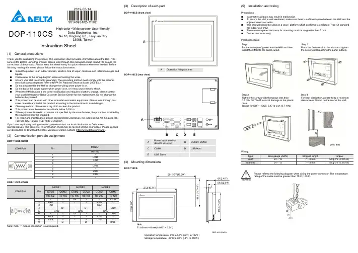
DOP -110CSHigh color ‧Wide screen ‧User-friendlyDelta Electronics, Inc.No.18, Xinglong Rd., Taoyuan City33068, TaiwanInstruction Sheet(1) General precautionsThank you for purchasing this product. This instruction sheet provides information about the DOP-100 series HMI. Before using this product, please read through this instruction sheet carefully to ensure the correct use of the product. Please keep this sheet handy for quick reference whenever needed. Before finishing reading this sheet, please follow the instructions below: ⏹ Install the product in an indoor location, which is free of vapor, corrosive and inflammable gas and liquids.⏹ Please refer to the wiring diagram when connecting the wires.⏹ Ensure your HMI is correctly grounded. The grounding method must comply with the national electrical standard (please refer to NFPA 70: National Electrical Code, 2005 Ed.). ⏹ Do not disassemble the HMI or change the wiring when power is on.⏹ Do not touch the power supply when power is on, or it may cause electric shock.⏹ When the HMI displays a low power notification and requires a battery change, please contact your local distributor or Delta Customer Service Center for the replacement. Do not change the batteries by yourself.⏹ This product can be used with other industrial automation equipment. Please read through this sheet carefully and install the product according to the instructions to avoid danger. ⏹ Cleaning method: please use a dry cloth to clean the product. ⏹ This product must be used at an altitude below 2,000 m.⏹ If the equipment is used in a manner not specified by the manufacturer, the protection provided by the equipment may be impaired.⏹For repair and maintenance, please contact Delta Electronics, Inc. Address: No.18, Xinglong Rd., Taoyuan City, Taiwan. TEL: +886-3-3626301.If you have any inquiry during operation, please contact our local distributors or Delta salesrepresentatives. The content of this instruction sheet may be revised without prior notice. Please consult our distributors or download the latest version at Delta’s website (/ia).(2) Communication port pin assignmentDOP-110CS COM1COM PortPin MODE1 RS-2321 -2 RXD3 TXD4 -5 GND6 -7 RTS 8CTS 9-DOP-110CS COM2COM PortPinMODE1MODE2 MODE3 COM2COM3COM2COM3COM2COM3RS-232 RS-485RS-485 RS-485RS-232 RS-4221 - - D+ - -TXD+ 2 RXD - - - RXD - 3 TXD - - - TXD - 4 -D+- D+ -RXD+5 GND GND GND6 - - D- - -TXD- 7 RTS - - - RTS- 8 CTS - - - CTS - 9- D- - D- - RXD-Note: mark “-” means connection is not required.(3) Description of each partDOP-110CS (front view)A Operation / display areaDOP-110CS (rear view)A Power input terminal (24AWG wire min.)B COM2 / COM3C COM1D USB HostEUSB Slave(4) Mounting dimensionsDOP-110CSUnit: mm (inch)Operation temperature: 0o C to 50o C (32o F to 122o F)Storage temperature: -20o C to 60o C (-4o F to 140o F)(5) Installation and wiringPrecautions: ⏹ Incorrect installation may result in malfunction.⏹ To ensure the HMI is well ventilated, make sure there is sufficient space between the HMI and the adjacent objects or walls.⏹ This product should be used on a case / platform which conforms to enclosure Type 4X standard (for indoor use only).⏹ The maximum panel thickness for mounting must be no greater than 5 mm. ⏹Copper conductor only.Installation steps:Step 1:Put the waterproof gasket into the HMI and then insert the HMI into the panel cutout.Step 2:Place the fasteners into the slots and tighten the screws until reaching the panel cutouts.Step 3:Tighten the screws with the torque less than 0.5 N-M / 0.7 N-M to avoid damage to the plastic case.Torque for DOP-110CS: 6.17 lb-inch (0.7 N-M)Step 4:For heat dissipation, please keep a minimum clearance of 60 mm on the rear of the HMI.Wiring:Type Wire gauge (AWG)Stripped length TorqueSolid 24 – 12 7 – 8 mm 5 kg-cm (4.3 lb-in) Stranded 24 – 127 – 8 mm5 kg-cm (4.3 lb-in)Please refer to the following diagram when wiring the power connector. The temperature rating of the cable must be greater than 75o C (167o F).(6) Hardware specificationsModel DOP-110CSDisplayPanel type 10.1" TFT LCD (65535 colors)Resolution 1024 x 600 pixelsBacklightLED Back Light(half-life under room temperature 25o C > 20,000 hours)*1 Displayrange226 mm x 128.7 mmBrightness 300 cd / m² (Typ.)CPU ARM Cortex-A8 (800 MHz)Flash ROM 256 MbytesRAM 256 MbytesTouchscreen 4-wire resistive touchscreen > 1,000,000 operated Buzzer Multi-tone Frequency (2K - 4K Hz) / 80dB Network interface N/AUSB 1 USB Slave Ver. 2.0; 1 USB Host Ver. 2.0SD N/ASerial communicationport COM1 RS-232 (supporting flow control)*2 COM2 RS-232 (supporting flow control) / RS485*2 COM3 RS-422 / RS-485*2Auxiliary function key N/A Calendar Built-in Cooling method Natural coolingApprovals CE / UL (please use shielding network cable and magnetic ring withthe filter of 300 ohm / 100 MHz)Panel waterproof level IP65 / NEMA4 / UL TYPE 4X (indoor use only)Operation voltage*2DC +24V (-15% to +15%) (please use an isolated power supply) Supplied by Class 2 or SELV circuit (isolated from MAINS by double insulation)Leakage current 500 V AC for 1 minute (between DC24V terminal and FG terminal) Power consumption*210.4 W (Max) *3Backup battery 3V lithium battery CR2032 × 1Backup battery lifeAbout 3 years or more at 25o C (subject to operation temperature and condition)Operation temperature 0o C to 50o C (32o F to 122o F) Storage temperature -20o C to +60o C (-4o F to 140o F)Operating environment 10% to 90% RH [0o C - 40o C], 10% to 55% RH [41o C - 50o C];pollution degree: 2Vibration resistance Conforms to IEC61131-2: continuous vibration 5 Hz - 8.3 Hz with amplitude 3.5 mm; 8.3 Hz - 150 Hz with amplitude 1GShock resistanceConforms to IEC60068-2-27:11 ms, 15 G Peak, in X, Y, Z directions each for 6 timesDimension(W) x (H) x (D) mm272 x 200 x 61Mounting dimension(W) x (H) mm261.3 x 189.3Weight Approx. 1330 gNote:1. The half-life of the backlight is defined as the maximum luminance being reduced by 50% when themaximum drive current is supplied to the HMI. The life of LED backlight shown here is estimated at the room temperature of 25o C with ambient humidity.2. The withstand voltage of the isolated power circuit is 1500V peak for 1 minute.3. The HMI power consumption is the power consumed when the HMI is not connecting with otherperipheral devices. To ensure normal operation of the HMI, the recommended capacity of the power supply is 1.5 to 2 times of the specified power consumption.4. Isolated power supply is recommended.5. For the DOPSoft programming software of the DOP-100 series and the user manual, you candownload them at /ia.6. DOP-100 series can be used with other industrial automation equipment. Please read through thissheet carefully and install the product according to the instructions to avoid danger.DOP -110CSYüksek Renk ‧ Geniş Ekran ‧ Kullanıcı Dostu HMIÜrünleriNo.18, Xinglong Rd., Taoyuan City 33068, TaiwanBilgi Dokümanı(1) ÖnsözBu ürünü satın aldığınız için teşekkür ederiz. Bu bilgi dokümanı DOP-100 serileri için bilgiler sağlar. Ürünü kullanmadan önce, doğru şekilde kullanım sağlamak için lütfen dokümanı tamamen okuyunuz. Ayrıca daha sonra ihtiyaç duyulduğunda kullanabilmek için bu dokümanı iyi muhafaza ediniz. Bu dokümanı okumayı bitirdikten sonra lütfen aşağıda yazılı olan talimatları uygulayınız.⏹ Ürünün kurulumunu aşındırıcı, yanıcı gaz veya sıvılardan uzak, temiz ve kuru yerlere yapınız.Sadece iç mekânda kullanınız⏹ Tüm bağlantıların dokümanda belirtildiği gibi olduğuna emin olunuz.⏹ HMI toprak bağlantısının doğru olduğuna emin olunuz. Topraklama metodu uluslararası elektrikstandardına uyumlu olmalıdır (NFPA 70: National Electrical Code, 2005 Ed). ⏹ Ürün enerjili iken HMI’ı sökmeyiniz ve bağlantılara müdahale etmeyiniz.⏹ Çalışma sırasında güç kaynağına dokunmayınız. Aksi halde elektrik çarpması meydana gelebilir. ⏹ HMI düşük pil uyarısı gösterirse ve pil değişimi gerekirse lütfen firmamız ile temasa geçiniz,kendiniz değiştirmeyiniz.⏹ DOP-100 serisi endüstriyel otomasyon ekipmanı olarak kullanılır. Lütfen bu dokümanı dikkatliokuyun ve tehlikeli durumları önlemek için ürünü belirtilen direktiflere uygun kurunuz. ⏹ Temizleme metodu: Ürünü temizlemek için kuru bir bez kullanınız. ⏹ Ürün 2000m altında bir rakımda kullanılmalıdır.⏹ Eğer ürün imalatçı tarafından belirtilmeyen bir şekilde kullanılıyorsa, ürün tarafından sağlanankoruma bozulabilir.⏹ Ürünle ilgili sorularınız için firmamız ile kontak kurabilirsiniz.Ürünün kullanımı ile ilgili sorularınız için teknik servisimizle kontak kurabilirsiniz. Bu bilgi dokümanının içeriği herhangi bir bildirime gerek duyulmadan değiştirilebilir. Dokümanın son versiyonunu internetten indirebilirsiniz. /ia .(2) Haberleşme PinleriDOP-110CS COM1 portCOM PortPin MOD 1 RS-2321 -2 RXD3 TXD4 -5 GND6 -7 RTS 8CTS 9-DOP-110CS COM2 portCOM PortPin MOD 1MOD 2 MOD 3COM2COM3COM2COM3COM2 COM3RS-232 RS-485RS-485 RS-485RS-232 RS-4221 - - D+ - -TXD+ 2 RXD - - - RXD - 3 TXD - - - TXD - 4 - D+- D+ -RXD+5 GND GND GND6 - - D- - - TXD-7 RTS - - - RTS -8 CTS- - - CTS - 9- D- - D- - RXD-Not: “-“ olarak yazılan pinlere bağlantı yapılmaz.(3) Parça AçıklamalarıDOP-110CS (Ön Görünüm)ADokunmatik Ekran / DisplayDOP-110CS (Arka Görünüm)A Güç Giriş Soketi(24AWG kablo min.)B COM2 / COM3C COM1D USB Host EUSB Slave(4) Montaj ÖlçüleriDOP-110CSÇalışma Sıcaklığı: 0o C ~ 50o C (32o F ~ 122o F)Birim: mm (inç)Depolama Sıcaklığı: -20o C ~ 60o C (-4o F ~ 140o F)(5) Montaj ve KablolamaÖnlemler: ⏹ Yanlış kurulum arızalara sebep olabilir.⏹ HMI’ın iyi havalandırıldığından emin olmak için, HMI ile yakın objeler veya duvarlar arasında yeterli boşluk olduğundan emin olun.⏹ Bu ürün, 4X standartına uygun bir kasa / platform (sadece kapalı alanda kullanım) üzerinde kullanılmalıdır.⏹ Montaj için kullanılan panelin kalınlığı 5 mm’den az olmalıdır. ⏹Sadece bakır kondansatör.Montaj için kullanılan panelin kalınlığı 5 mm’den az olmalıdır. Adım 1:HMI içine su geçirmez contanın takıldığına emin olunuz ve sonra pano boşluğuna yerleştiriniz.Adım 2:Montaj aparatlarını HMI’ın yuvalarınayerleştiriniz ve sonra panoya değene kadar vidaları sıkınız.Adım 3:Plastik kasaya zarar vermemek için vidayı 0.5 N-M’den fazla 0.7 N-M’den az tork ile sıkınız. DOP-110CS Tork: 6.17 lb-inç (0.7N-M)Adım 4:Isı dağılımı sağlanabilmesi için HMI arka paneli ile duvar, kurulum yüzeyi veya başka kontrol cihazı ile arasında en ez 60 mm boşluk bırakınız.Kablolama: Tip Kablo Ölçüsü (AWG)Soyma UzunluğuTork Tek Damarlı 24 - 12 7 - 8 mm 5 kg-cm (4.3 lb-in) Çok Damarlı 24 - 127 - 8 mm5 kg-cm (4.3 lb-in)Besleme konektörü bağlantısının aşağıdaki şekilde gösterildiği gibi yapıldığına emin olunuz. Kablo sıcaklık dayanım derecesi 75o C (167o F)’den yüksek olmalıdır.(6) Donanımsal ÖzelliklerModel DOP-110CSEkranPanel Tipi 10.1" TFT LCD (65535 Renk)Çözünürlük 1024 x 600 PikselAydınlatma LED Aydınlatma (Yarım ömürde 25o C’de 20,000 saatten az) *1 Ekran Ölçüsü 226 mm x 128.7 mmParlaklık 300 cd / m² (Tipik)CPU ARM Cortex-A8 (800 MHz)Flash ROM 256 MbytesRAM 256 MbytesDokunmatik 4 kablolu Rezistif Dokunmatik Ekran > 10,000,000 dokunma Buzzer Multi-tone Frequency (2K - 4K Hz) / 80dB Ethernet Arabirimi YokUSB 1 USB Slave Ver. 2.0; 1 USB Host Ver. 2.0SD YokSeri HaberleşmePortu COM1 RS-232 (Flow Kontrol Destekler)*2 COM2 RS-232 (Flow Kontrol Destekler) / RS485*2 COM3 RS-422 / RS-485*2Fonksiyon Tuşları Yok Takvim DâhiliSoğutma Metodu Doğal SoğutmaSertifikalar CE / UL (Lütfen ekranlı Ethernet kablosu ve 300 ohm/100 MHz filtreile manyetik halka kullanınız)Su Geçirmezlik Seviyesi IP65 / NEMA4 / UL Tip 4X (Bina içi kullanım içindir)Çalışma Voltajı *2DC +24V (-15% ~ +15%) (Lütfen dâhili filtreli güç kaynağı kullanınız.) SELV ile beslenir. (Şebeke hattından çift yalıtım ile izole edilmiştir)Kaçak Akım Dayanımı 1 dakika için 500 V AC (DC24V terminal ve FG terminalleri arası) Güç Tüketimi *210.4 W (Maks) *3Yedekleme Pili 3V lityum pil CR2032 × 1Yedekleme Pil Ömrü Normal koşullarda 25o C’de 3 yıl veya daha fazla.Çalışma Sıcaklığı 0o C ~ 50o C (32o F ~ 122o F)Depolama Sıcaklığı -20o C ~ +60o C (-4o F ~ 140o F)Çalışma Ortamı 10% ~ 90% RH [0o C - 40o C], 10% ~ 55% RH [41o C - 50o C];Kirlenme Derecesi: 2Titreşim Direnci IEC61131-2 ile uyumlu; Sürekli: 5 Hz ~ 8.3 Hz 3.5 mm, 8.3 Hz ~ 150Hz 1 GŞok Direnci IEC60068-2-27 ile uyumlu: 11 ms, 15 G Pik, X, Y, Z yönünde 6 kereÖlçüleri(G) x (Y) x (D) mm272 x 200 x 61Kesim Ölçüleri(G) x (Y) mm261.3 x 189.3Ağırlık Yaklaşık. 1330 gNot:1. Arka ışık yarı-ömrü maksimum besleme akımı HMI'ya uygulandığında orijinal parlaklığın %50oranında azaltılmış olması olarak tanımlanır. Burada gösterilen LED aydınlatma ömrü 25o C normal sıcaklık ve nem koşullarında tahmini bir değerdir.2. İzoleli güç devresi dayanma voltajı 1 dakika için 1500 V pik.3. HMI güç tüketimi herhangi bir cihaza bağlı değil iken tükettiği güçtür. Normal çalışma için tavsiyeedilen güç kaynağı tüketilen gücün 1.5 ~ 2 katıdır.4. İzoleli güç kaynağı kullanılması tavsiye edilir.5. DOP-100 serisi ürünlerin program editörü olan DOPSoft programı ve kullanıcı manuel’i websayfamızdan indirilebilirsiniz. /ia.6. DOP-100 serisi endüstriyel otomasyon donanımı olarak kullanılabilir. Tehlikeleri önlemek için bu bilgidokümanını dikkatlice okuyun ve belirtilen direktiflere göre kurulumu gerçekleştirin.DOP -110CS高彩‧寬螢幕‧友善人機介面Delta Electronics, Inc,No.18, Xinglong Rd., Taoyuan City33068, Taiwan安裝說明(1) ⼀般注意事項感謝您使用本產品,本人機介面安裝說明書提供DOP-100系列人機介面的相關資訊。
触摸屏培训资料(一)引言概述触摸屏技术是一种现代化的交互方式,已经广泛应用于各种设备和系统中。
为了充分发挥触摸屏的功能,需要专门的培训资料来指导用户正确地使用和操作触摸屏。
本文档将介绍和解释触摸屏的基本知识和技巧,帮助读者快速上手并提高使用效果。
正文内容1. 触摸屏的基本原理1.1 电容触摸屏原理1.2 电阻触摸屏原理1.3 表面声波触摸屏原理1.4 其他类型触摸屏的原理介绍1.5 触摸屏的优缺点分析2. 触摸屏的常见手势操作2.1 单指触摸操作2.2 双指触摸操作2.3 多指触摸操作2.4 旋转、缩放和拖拽手势操作2.5 其他常见的触摸屏手势操作3. 触摸屏的使用技巧和注意事项3.1 触摸屏的保养与清洁3.2 如何准确地点击、滑动和拖拽3.3 触摸屏的快捷操作技巧3.4 避免误操作和屏幕反应延迟的解决方法3.5 触摸屏在特殊环境下的适应性和限制4. 触摸屏的适用场景与应用案例4.1 商业展示与交互应用4.2 智能手机和平板电脑的触摸屏应用4.3 医疗设备和工业控制系统的触摸屏应用4.4 汽车导航和娱乐系统的触摸屏应用4.5 其他领域触摸屏应用的创新案例介绍5. 触摸屏常见问题解答和故障排除5.1 如何识别触摸屏故障类型5.2 常见的触摸屏问题及解决办法5.3 如何避免触摸屏问题出现的常见误区5.4 有关触摸屏维修和更换的注意事项5.5 触摸屏故障排除的高级技巧和维修方法总结通过本文档的学习,读者将掌握触摸屏的基本原理、常见手势操作、使用技巧和注意事项。
同时,了解触摸屏的适用场景和应用案例,并能够解决触摸屏常见问题和故障排除。
希望读者能够通过本文档快速上手并提高触摸屏的使用效果。

触摸屏品质培训课件xx年xx月xx日•触摸屏品质控制概述•触摸屏品质检验与常见问题分析•触摸屏生产过程的质量控制•触摸屏品质的持续改进与优化目•触摸屏品质控制的创新技术与发展趋势•实际案例分享与经验交流录01触摸屏品质控制概述触摸屏品质包括准确性、稳定性、可靠性、寿命等指标,直接影响用户体验和产品竞争力。
触摸屏品质控制对于提高产品质量和降低生产成本具有重要意义,是企业发展的关键环节之一。
触摸屏品质的概念与重要性触摸屏品质控制的基本流程严格把控原材料的质量,建立完善的供应商管理制度。
原材料采购与检验生产过程控制半成品和成品检验问题反馈与处理制定科学合理的生产流程和工艺,确保生产过程中的品质稳定。
通过先进的检测手段和严格的检验标准,对半成品和成品进行品质检测。
及时反馈生产过程中出现的问题,建立问题处理机制,预防类似问题的再次出现。
触摸屏品质的国内外发展现状部分企业在触摸屏品质控制方面取得了一定的成绩和经验,但仍需不断提高和完善。
行业标准不断完善,推动触摸屏品质控制的标准化和规范化。
触摸屏品质技术不断发展,国内外企业逐步加强技术研发和产业布局。
02触摸屏品质检验与常见问题分析根据触摸屏产品的行业标准和公司内部标准进行检验。
触摸屏品质检验的方法与标准按照检验标准对触摸屏的外观进行仔细观察,包括是否有划痕、气泡、色差等不良品特征。
外观检验通过测试设备对触摸屏的各项性能指标进行检测,如灵敏度、精确度、响应时间等。
性能测试性能问题灵敏度低、定位不准确、响应时间长等,可能是由于生产过程中材料、工艺等因素导致。
外观问题表面划痕、气泡、色差等,可能是由于生产过程中操作不当或运输过程中造成。
兼容性问题与特定设备或系统不兼容,可能是由于操作系统、驱动程序或硬件配置等因素造成。
常见触摸屏品质问题的分类与原因触摸屏反应迟钝,灵敏度低。
原因分析:可能是由于表面有污渍或油脂,影响到了触摸屏的感应。
解决方案:使用干净的布或纸巾清除表面污渍和油脂,然后重新测试。
DOP基础知识学习目录一、内容概述 (2)二、基础知识概述 (3)三、DOP基础知识详解 (4)1. DOP定义及概念 (6)2. DOP的发展历程 (7)3. DOP的应用领域 (9)四、技术原理及实现方式 (10)1. DOP的技术原理 (11)1.1 基础技术介绍 (12)1.2 技术内部运行机制 (13)2. DOP的实现方式 (14)2.1 软件实现 (15)2.2 硬件实现 (17)2.3 软件硬件结合实现 (19)五、DOP基础知识学习重点及难点解析 (20)1. 学习重点 (21)2. 难点解析及应对策略 (22)六、实际操作指导及案例分析 (24)1. 操作指导 (26)2. 案例分析 (27)七、DOP发展趋势及前景展望 (28)1. DOP的发展趋势 (30)2. DOP的前景展望与预测 (31)八、学习资源推荐及学习方法建议 (32)1. 学习资源推荐 (33)2. 学习方法建议与技巧分享 (34)九、总结与回顾 (35)1. 知识体系梳理与总结 (36)2. 回顾学习过程中的收获与不足 (37)一、内容概述DOP基本概念:简要介绍DOP的定义、背景以及它在相关领域的重要性,帮助学习者对DOP有一个初步的认识。
基础知识:详细介绍DOP的基础理论知识,包括其基本原理、核心要素、基本架构等,为学习者打下扎实的基础。
技术细节:详细阐述DOP技术的具体操作步骤、技术要点、关键参数等,使学习者能够掌握实际操作技能。
应用场景:列举DOP技术在不同领域的应用实例,包括具体的应用场景、实施过程、效果评估等,帮助学习者理解DOP的实际应用价值。
实践操作:提供一系列实践操作指导,包括实验设计、数据收集、分析方法和报告撰写等,帮助学习者将理论知识转化为实际操作能力。
常见问题与解决方案:列出学习者在DOP学习过程中可能遇到的常见问题,并提供相应的解决方案和注意事项,帮助学习者顺利解决学习中遇到的问题。