Characterization of PTFE Using Advanced Thermal Analysis Techniques
- 格式:pdf
- 大小:292.60 KB
- 文档页数:9

工 程 塑 料 应 用ENGINEERING PLASTICS APPLICATION第49卷,第6期2021年6月V ol.49,No.6Jun. 2021118doi:10.3969/j.issn.1001-3539.2021.06.021聚四氟乙烯压缩蠕变行为测试与表征雷淼,周健,李孟茹,晁敏,颜录科(长安大学材料科学与工程学院,西安 710064)摘要:为研究聚四氟乙烯(PTFE)压缩蠕变行为,自行设计制造压缩蠕变试验装置,分别对其常温与高温压缩蠕变性能进行测试,建立PTFE 压缩蠕变模型和蠕变方程,对所得压缩蠕变性能数据进行非线性拟合分析。
结果表明,自制高温压缩蠕变测试仪实现了由室温到250℃范围内、不同载荷作用下材料长期压缩蠕变性能测试的自动化操作;PTFE 在压缩蠕变过程中并不表现出黏性流动形变,但当其表现出与一般材料相同的典型蠕变行为时,推迟时间要比其它条件下大许多,当发生蠕变断裂时推迟时间将提高近一个数量级。
所建立的七元件蠕变模型能全面地反映PTFE 的压缩蠕变行为,可预测PTFE 的长时力学行为、使用寿命以及疲劳与失效等。
蠕变拟合曲线与测试数据吻合良好,拟合精度高。
关键词:聚四氟乙烯;复合材料;压缩蠕变;测试;表征中图分类号:TQ327.3 文献标识码:A 文章编号:1001-3539(2021)06-0118-07Testing and Characterization of Compressive Creep Behavior in PolytetrafluoroethyleneLei Miao , Zhou Jian , Li Mengru , Chao Min , Yan Luke(School of Materials Science & Engineering , Chang ’an University , Xi'an 710064, China)Abstract :In order to study the compression creep behavior of polytetrafluoroethylene (PTFE),the compression creep test device was designed and manufactured by ourselves ,the normal temperature and high temperature compression creep properties of PTFE were tested ,and the PTFE compression creep model and creep equation were established ,and then nonlinear fitting analysis was performed on the obtained compression creep performance data. The results show that the self-made high-temperature compression creep tester realizes the automatic operation of the long-term compression creep performance test of materials under different loads from room temperature to 250℃. PTFE does not exhibit viscous flow deformation during compression and creep ,but when it exhibits the same typical creep behavior as general materials ,the delay time is much longer than under other conditions ,and when creep rupture occurs ,the delay time increases by nearly one order of magnitude. The established seven-element creep model can fully reflect the compression creep behavior of PTFE ,and can predict the long-term mechanical behavior ,service life ,fatigue ,and failure of PTFE. The creep fitting curve is in good agreement with the test data ,and the fitting accuracy is high.Keywords :polytetrafluoroethylene ;composite ;compressive creep ;testing ;characterization几乎所有材料都会发生蠕变,而塑料材料特别显著,在常温下就会有明显的蠕变。
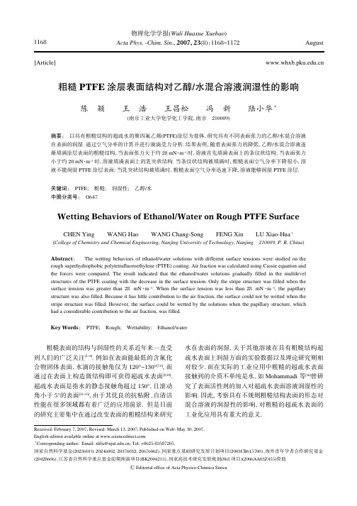
[Article]物理化学学报(Wuli Huaxue Xuebao )Acta Phys.鄄Chim.Sin .,2007,23(8):1168-1172AugustReceived:February 7,2007;Revised:March 13,2007;Published on Web:May 30,2007.English edition available online at ∗Corresponding author.Email:xhlu@;Tel:+8625⁃83587205.国家自然科学基金(20236010,20246002,20376032,20676062)、国家重点基础研究发展计划项目(2003CB615700)、海外青年学者合作研究基金(20428606)、江苏省自然科学重点基金前期预演项目(BK2004215)、国家高技术研究发展规划(863项目)(2006AA03Z455)资助ⒸEditorial office of Acta Physico ⁃Chimica Sinica粗糙PTFE 涂层表面结构对乙醇/水混合溶液润湿性的影响陈颖王浩王昌松冯新陆小华∗(南京工业大学化学化工学院,南京210009)摘要:以具有粗糙结构的超疏水的聚四氟乙烯(PTFE)涂层为基体,研究具有不同表面张力的乙醇/水混合溶液在表面的润湿.通过空气分率的计算并进行液滴受力分析.结果表明,随着表面张力的降低,乙醇/水混合溶液逐渐填满涂层表面的粗糙结构,当表面张力大于约28mN ·m -1时,溶液首先填满表面上的条纹状结构;当表面张力小于约28mN ·m -1时,溶液填满表面上的乳突状结构.当条纹状结构被填满时,粗糙表面空气分率下降很小,溶液不能润湿PTFE 涂层表面;当乳突状结构被填满时,粗糙表面空气分率迅速下降,溶液能够润湿PTFE 涂层.关键词:PTFE;粗糙;润湿性;乙醇/水中图分类号:O647Wetting Behaviors of Ethanol/Water on Rough PTFE SurfaceCHEN Ying WANG Hao WANG Chang ⁃Song FENG Xin LU Xiao ⁃Hua ∗(College of Chemistry and Chemical Engineering,Nanjing University of Technology,Nanjing210009,P.R.China )Abstract :The wetting behaviors of ethanol/water solutions with different surface tensions were studied on therough superhydrophobic polytetrafluoroethylene (PTFE)coating.Air fraction was calculated using Cassie equation and the forces were compared.The result indicated that the ethanol/water solutions gradually filled in the multilevel structures of the PTFE coating with the decrease in the surface tension.Only the stripe structure was filled when the surface tension was greater than 28mN ·m -1.When the surface tension was less than 28mN ·m -1,the papillary structure was also filled.Because it has little contribution to the air fraction,the surface could not be wetted when the stripe structure was filled.However,the surface could be wetted by the solutions when the papillary structure,which had a considerable contribution to the air fraction,was filled.Key Words :PTFE;Rough;Wettability;Ethanol/water粗糙表面的结构与润湿性的关系近年来一直受到人们的广泛关注[1-6].例如在表面能最低的含氟化合物固体表面,水滴的接触角仅为120°-130°[7,8],而通过在表面上构造微结构即可获得超疏水表面[9,10].超疏水表面是指水的静态接触角超过150°,且滚动角小于5°的表面[11-15],由于其优良的抗粘附、自清洁性能在很多领域都有着广泛的应用前景.但是目前的研究主要集中在通过改变表面的粗糙结构来研究水在表面的润湿,关于其他溶液在具有粗糙结构超疏水表面上润湿方面的实验数据以及理论研究则相对较少.而在实际的工业应用中粗糙的超疏水表面接触到的介质不单纯是水,如Mohammadi 等[16]曾研究了表面活性剂的加入对超疏水表面溶液润湿性的影响.因此,考察具有不规则粗糙结构表面的形态对混合溶液的润湿性的影响,对粗糙的超疏水表面的工业化应用具有重大的意义.1168No.8陈颖等:粗糙PTFE涂层表面结构对乙醇/水混合溶液润湿性的影响为了考虑溶液的表面张力与表面结构之间的关系对溶液在粗糙超疏水表面润湿性的影响,本文拟通过控制体积比来获得具有不同表面张力的乙醇/水混合溶液,以具有不规则粗糙结构的超疏水聚四氟乙烯(PTFE)涂层为基体,通过测量混合溶液在涂层上的静态接触角及理论分析,研究溶液的表面张力以及粗糙PTFE表面不同尺度结构共同作用对润湿性的影响.1试验部分1.1试剂PTFE乳液(固含量为60%,w),由浙江巨化股份有限公司提供;无水乙醇为分析纯,由南京宁试化学试剂有限公司提供.以不同体积比的去离子水与无水乙醇配成具有不同表面张力的乙醇/水混合溶液,待用.1.2样品制备取大小约2cm×3cm的铝片,先采用200目金相砂纸打磨,去除金属表面氧化层,然后用800目金相砂纸磨至表面均匀细致;用无水乙醇进行表面清洗,再用去离子水洗净,烘干备用.采用F75型上吸式喷枪(台湾得力气动工具有限公司)将PTFE乳液均匀地喷涂在铝片表面,每喷涂完一层后将铝片放入电热恒温鼓风干燥箱中,在90℃进行固化20min;将制备好的基片放入马弗炉,从室温升温至370℃,保温0.5h后随炉冷却,即可制得粗糙PTFE涂层[17].采用TC100AG型精密旋转涂层机(MIT Corpo⁃ration)制备平整PTFE涂层.以洁净的载玻片为基体,采用针管将0.1mL PTFE乳液滴在载玻片中心,旋转涂膜转速为3000r·min-1.将涂膜后的基片放入马弗炉,从室温升温至370℃,保温0.5h后随炉冷却,即可制得平整PTFE涂层.在平整表面上进行接触角的测量,以获得液体的本征接触角θa,0.1.3样品表征采用JSM5600LV型扫描电子显微镜(日本电子株式会社)对制备的PTFE涂层进行形貌的表征;采用BYZ⁃1型表面张力仪(上海衡平仪器厂)进行液体表面张力的测量,测量时每种液体测试四次,取平均值;采用DSA100型视频光学接触角测量仪(Kruss, Germany)测量滚动角和液滴在涂层表面的接触角.测量时选择3块平行样片,每种液体在每块样片上随机选取8处测量接触角取平均值,接触角测量误差范围为±2°,测量液体体积取5μL.2结果与讨论2.1粗糙涂层的形貌表征采用SEM对制备的粗糙PTFE涂层表面形貌进行表征.图1为超疏水PTF涂层表面的SEM图.图1(a)表明PTFE涂层表面随机分散的大小不一的微米级乳突结构.对其中一个乳突放大观察,见图1 (b),可以发现在乳突结构上存在着条状结构.通过测量水滴在涂层的静态接触角约(155±2)°,滚动角为3°,涂层具有超疏水性.图1(c)表明PTFE涂层的厚度约为100μm.本文采用喷涂法所制备的PTFE涂层,其表面具有随机分布的复杂结构,但这些结构存在着一定的规律性,因此为了获得简化模型首先将图1(a)中的乳突状结构定义为一次结构,图1(b)中条纹状结构定义为二次结构.整个涂层表面可以简化为由两种形式结构构成的粗糙表面.图1(d)为采用旋转涂膜法制备的PTFE涂层的SEM图,PTFE涂层表面较平整.水滴在其上的接触角为110°,与文献报道的平整PTFE表面水的接触角值[18]相吻合.本文采用旋转涂膜法制备的PTFE涂层作为PTFE平整表面使用,以获得液体的本征接触角.图1超疏水PTFE涂层表面SEM图Fig.1SEM images of superhydrophobic PTFE coating(a)SEM image of large⁃area sprayed PTFE coating;(b)high magnify image of single papilla;(c)sectional SEM image of superhydrophobicPTFE coating;(d)SEM image of smooth PTFE coating;θ:contact angle1169Acta Phys.鄄Chim.Sin.,2007Vol.232.2乙醇/水混合溶液在超疏水PTFE 表面润湿性的研究在室温(25±2℃)下分别测定了不同体积比的乙醇/水混合溶液的表面张力以及溶液在粗糙PTFE 涂层和平整PTFE 表面上的接触角,见图2.图2表明,在具有粗糙结构的超疏水PTFE 表面,混合溶液的接触角随着表面张力的下降而下降.但在下降的过程中很明显出现了两种趋势,以表面张力值约为28mN ·m -1为临界点分为两个阶段,第一阶段即表面张力值大于28mN ·m -1时,混合溶液在粗糙表面上的接触角值下降的趋势较缓慢,且接触角值始终大于120°,即液体此时不能润湿粗糙表面;第二阶段即表面张力值小于28mN ·m -1时,接触角值急剧下降,由122°迅速下降至53°,溶液在表面上迅速由不润湿转变为可润湿.溶液在粗糙表面上从不润湿到润湿状态随着表面张力的变化出现了突变,而在平整表面上则无突变的现象.液滴在平整表面上的接触角即本征接触角小于90°时,液滴可以润湿粗糙表面的结构.此时溶液在粗糙表面上的接触角与液滴未润湿粗糙表面结构时的接触角相比会有明显差别[19].根据图2分析,比较混合溶液在平整和粗糙PTFE 涂层表面上接触角随表面张力变化的曲线可知,当混合溶液的本征接触角小于90°时,溶液在粗糙表面上接触角的下降趋势并没有非常明显的变化,即不同表面张力时接触角的值差别不大.直到溶液的本征接触角小于60°后,溶液在粗糙PTFE 表面的接触角才出现了急剧的下降,不同表面张力溶液的接触角值差别比较明显.粗糙PTFE 涂层表面的水静态接触角约为(155±2)°,滚动角为3°.由于滚动角很小,水在表面的润湿符合Cassie 方程,即水与固体表面与空气所构成的复合表面相接触[14].根据式(1)计算涂层表面的空气分率为0.86.而对于乙醇/水混合溶液在超疏水PTFE 表面由于表面张力不同导致润湿情况发生变化,空气分率也会随溶液表面张力的下降而相应变化,见图3,采用式(1)计算.cos θCB =(1-f )cos θa,0-f(1)式(1)中θCB 为表观接触角,即溶液在粗糙表面上测得的接触角;θa,0为本征接触角,即液体在平整表面上的接触角;f 为空气分率,即复合接触表面中液气接触所占的百分数.图3表明,随着乙醇/水混合溶液表面张力的下降,空气分率整体下降,但下降的趋势也分为两个阶段,在第一阶段空气分率由0.86缓慢下降至0.70;而在第二阶段,空气分率由0.70迅速下降至0.10.这种阶段性变化表明,混合溶液在表面上的润湿形式发生了变化,而这种变化很可能与粗糙的结构相关.2.3润湿性与表面粗糙结构关系的理论分析小液滴在粗糙表面上受到体相力F body (见方程(2))和表面力F surface (见方程(3))共同作用,F surface 使小液滴具有自动收缩的倾向,而F body 则使小液滴有铺展的倾向.不同的液体表面张力以及表面的粗糙结构导致液滴由于受力的不同将会出现两种润湿行为[9]:若F surface >F body ,则小液滴被支撑在表面,即液体不易润湿表面,如图4(a);若F surface <F body 则小液滴将塌陷,在粗糙面上铺展开,与粗糙表面完全接触,即液体润湿表面,如图4(b).F body =ρgV(2)图2乙醇水混合溶液在粗糙PTFE 涂层以及平整PTFE 表面上接触角(θ)与表面张力(γ)关系图Fig.2Contact angles (θ)of the water/ethanol mixtureon the rough and flat PTFE surfaceswith surface tension (γ)图3粗糙PTFE 表面乙醇/水混合溶液表面张力(γ)与空气分率(f )关系图Fig.3Air fraction (f )of the water/ethanol with different surface tensions on the rough PTFE coating1170No.8陈颖等:粗糙PTFE 涂层表面结构对乙醇/水混合溶液润湿性的影响式(2)中ρ为液体密度,g 为重力加速度,V 为液滴体积.F surface =-L γcos θ(3)式(3)中γ为液体表面张力,θ为实测接触角,L 为液滴边缘与固体表面实际接触线的长度.L =δl ,l 为液滴边缘与表面理想接触线的长度即液滴的底边圆周长,δ为粗糙表面的尺寸参数,如图5所示,δ=x /y ,x 为粗糙突起的特征尺寸,y 为两粗糙突起之间的距离,不同粗糙结构的表面具有不同的尺寸参数δ.同一种液体在具有不同的尺寸参数δ的表面上由于接触线不同,受力情况不同,润湿行为也会有不同.根据图1(a 、b)对粗糙的超疏水PTFE 涂层的结构进行简化.粗糙PTFE 涂层具有的一次结构(prima ⁃ry structure)和二次结构(secondary structure),可以简化为两种不同尺度,即间距不同的结构.并用SigmaScan 对12张不同放大倍数的涂层表面不同位置的SEM 图进行粗糙突起的尺寸以及间距测量,并用Statistic 统计分别统计一次结构上单个乳突结构的宽度,相邻两个乳突结构的距离,以及二次结构上条纹结构的宽度,相邻的条纹结构的间距,统计结果如图6.根据统计的数值采用δ=x /y 估算表面结构的尺寸参数.由图6(a 、b)可知,对于表面乳突状结构即一次结构,x 约为37.5μm,y 约为170μm,尺寸参数δP 为0.2.由图6(c 、d)可知对于条纹状结构即二次结构,x 约为0.325μm,y 约为3.57μm,尺寸参数δs 为0.1.分别根据式(2)和式(3)计算液滴在一次结构和二次结构上的体相力F body 和表面力F surface ,并进行比较,结果见表1.从表1可看到,在二次结构即条状结构上,乙醇/水混合溶液的表面张力小于50mN ·m -1时,表面力已经无法与体相力相抗衡,液滴在条状结构上塌陷,液体填满条纹状结构缝隙之间.在一次结构即乳突结构上,当乙醇/水混合溶液的表面张力小于28mN ·m -1时,表面力不能和体相力平衡,导致液滴在乳突状结构上塌陷,液体填满乳突状结构的缝隙之间.即随着表面张力逐步降低,溶液首先润湿条纹状结构,当溶液表面张力降至28mN ·m -1后,溶液润湿乳突状结构.结合溶液在粗糙PTFE 表面润湿时的空气分率变化图(图3)以及在具有不同尺寸参数的结构上液滴受力平衡的计算得到,根据力平衡的判断可知,当溶液表面张力大于28mN ·m -1,溶液在条纹状结构上受到的体相力大于表面力时,溶液在乳突状结构上受到的体相力仍然小于表面力,因此溶液此时只润湿条纹状结构.结合空气分率的变化图(图3)可知,随着表面张力的减小,当混合溶液表面张力大于28mN ·m -1时,空气分率呈现比较缓慢的下降趋势,由最大值0.86缓慢下降至0.70,变化幅度很小,因此可以推断条纹状结构对整体空气分率的贡献很小;当条纹状结构被溶液填满时,溶液仍然不能润湿粗糙PTFE 涂层,接触角大于120°,条纹状结构提供的图4小液滴在粗糙表面上的润湿形式Fig.4Small drops on rough surface(a)a suspended small drop on the rough surface;(b)a collapsed small drop on the rough surface图5粗糙表面结构示意图Fig.5Sketch map of a rough surface(a)plan view;(b)side view图6粗糙PTFE 涂层表面乳突状结构与条状结构的直径与间距统计分布图Fig.6The distributions of diameter and distance of the papillary and the stripe structures for PTFE coating(a)the diameter of the papillary structure;(b)the distance between two papillae;(c)the diameter of the stripe structure;(d)the distance between twostripes1171Acta Phys.⁃Chim.Sin.,2007Vol.23空气分率较小.而当溶液表面张力小于28mN ·m -1时,由力平衡的判断可知,溶液在乳突状结构以及条纹状结构上所受的体相力均大于表面力,此时溶液开始润湿乳突状结构.同时结合空气分率的变化可知,当表面张力小于28mN ·m -1时,随着表面张力的减小,空气分率急剧下降,由0.70迅速降至0.10.由此可以推断乳突状结构对表面空气分率的贡献远大于条纹状结构的贡献,当乳突状结构开始被填满时,空气分率立刻出现了很明显的变化,此时溶液在涂层表面的整体润湿形式也出现了变化,由不润湿转变为润湿.3结论本文以具有粗糙结构的超疏水PTFE 涂层为基体,通过测定具有不同表面张力的乙醇/水混合溶液的静态接触角,结合粗糙表面空气分率以及液滴受力平衡的计算得到:具有粗糙结构的PTFE 涂层表面的微观结构对溶液的润湿性有影响,当提供空气分率的结构被填满时,溶液在表面的润湿形式发生变化.乙醇/水混合溶液在超疏水粗糙PTFE 涂层上随着表面张力的减小,逐步润湿表面的粗糙结构.当表面张力大于28mN ·m -1时,混合溶液首先润湿对空气分率贡献较小的条纹状结构,溶液填满条纹状结构之间,空气分率缓慢下降,由0.86降至0.70,此时溶液在涂层上的接触角大于120毅,溶液不能润湿涂层表面;当表面张力小于28mN ·m -1时,溶液润湿对空气分率贡献较大的乳突状结构,即溶液填满乳突状结构之间导致空气分率急速减小,由0.70下降至0.10,溶液开始润湿涂层表面.References1Wenzel,N.R.Ind.Eng.Chem.,1936,28(8):9882Cassie,A.B.D.;Baxter,S.Trans.Faraday Soc.,1944,40:5463Yoshimitsu,Z.;Nakajima,A.;Watanabe,T.;Hashimoto,ngmuir,2002,18(15):58184Oner,D.;McCarthy,ngmuir,2000,16(20):77775Extrand,ngmuir,2006,22(4):17116Onda,T.;Shibuichi,S.;Satoh,N.;Tsujii,ngmuir,1996,12(9):21257Mahadevan,L.Nature,2001,411(6840):8958Nishino,T.;Meguro,M.;Nakamae,K.;Matsushita,M.;Ueda,ngmuir,1999,15(13):43219He,B.;Patankar,N.A.;Lee,ngmuir,2003,19(12):499910Bai,S.;Yang,L.L.;Zhang,M.F.;Yang,Z.H.;Zhang,Z.F.;Cao,W.X.Acta Phys.⁃Chim.Sin.,2006,22(10):1296[白硕,杨凌露,张茂峰,杨朝晖,张智峰,曹维孝.物理化学学报,2006,22(10):1296]11Nakajima,A.;Fujishima,A.;Hashimoto,K.;Watanabe,T.Adv.Mater.,1999,11(16):136512Aussillous,P.;Quere,D.Nature,2001,411(6840):92413Tadanaga,K.;Morinaga,J.;Matsuda,A.;Minami,T.Chem.Mater.,2000,12(3):59014Feng,L.;Li,S.H.;Li,Y.S.;Li,H.J.;Zhang,L.J.;Zhai,J.;Song,Y.L.;Liu,B.Q.;Jiang,L.;Zhu,D.B.Adv.Mater.,2002,14(24):185715Yu,Z.;Wang,Z.Q.;Jiang,Y.G.;Zhang,ngmuir,2006,22:448316Mohammadi,R.;Wassink,J.;Amirfazli,ngmuir,2004,20(22):965717Lu,X.H.;Wang,C.S.;Wang,H.;Feng,X.Preparation of hydrophobic and oleophobic fluorin coating strengthen by fine inorganic fibre.Chinese Patent,200510095423.7.2005[陆小华,王昌松,王浩,冯新.由无机超细纤催增强的超疏水和疏油含氟涂层的制备.中国专利,200510095423.7.2005]18Bodas,D.S.;Gangal,S.A.J.Micromech.Microeng.,2005,15(4):80219Cheng,Y.T.;Rodak,D.E.Appl.Phys.Lett.,2005,86:144101酌/(mN ·m -1)Secondary structure F body /μN F surface /μN F body /μN F surface /μN suspended or collapsed72.716.70937.81016.70918.905suspended 50.316.48133.40816.48116.704suspended 42.116.28528.61816.28514.309collapsed 31.415.83320.74115.83310.371collapsed 27.615.17117.34815.1718.674collapsed 25.414.32911.04114.329 5.520collapsed 24.113.824 6.11713.824 3.058collapsed 21.913.1567.44013.1563.720collapsedPrimary structuresuspended or collapsedsuspended suspended suspended suspended suspended collapsed collapsed collapsed表1体相力与表面力的比较Table 1Comparison of the body force to the surface force1172。

Advanced Materials CharacterizationAdvanced Materials Characterization is a field that plays a crucial role in the development and understanding of various materials used in industries such as aerospace, automotive, electronics, and healthcare. This discipline involves the use of various techniques and tools to analyze and characterize the properties and behavior of materials at the microscopic and macroscopic levels. In this response, I will discuss the importance of advanced materials characterization from multiple perspectives. From a scientific standpoint, advanced materials characterization provides valuable insights into the structure and properties of materials. By studying the composition, crystal structure, and defects in materials, researchers can gain a deeper understanding of their behavior and performance. This knowledge is essential for designing new materials with enhanced properties or improving the performance of existing materials. For example, by characterizing the microstructure of a metal alloy, scientists can determine its mechanical strength, corrosion resistance, and thermal stability, which are critical factors in industries such as aerospace and automotive. From an industrial perspective, advanced materials characterization is essential for quality control and ensuring the reliability of materials used in various applications. By characterizing the properties of materials, manufacturers can verify if they meet the required specifications and standards. This is particularly important in industries such as healthcare, where the use of substandard materials can have serious consequences for patient safety. By employing advanced characterization techniques such as scanning electron microscopy and X-ray diffraction, manufacturers can detect any defects or impurities in materials and take corrective actions before the final product is released. From an economic point of view, advanced materials characterization can contribute to the growth and competitiveness of industries. By developing new materials with improved properties, companies can gain a competitive edge in the market. For example, the development of lightweight and high-strength materials has revolutionized the aerospace industry, enabling the production of more fuel-efficient aircraft. Furthermore, advanced characterization techniques can help optimize manufacturing processes, leading to cost savings and increased productivity. From an environmental perspective, advanced materialscharacterization can contribute to the development of sustainable materials and technologies. By studying the environmental impact of materials throughout their life cycle, researchers can identify ways to reduce their carbon footprint and enhance their recyclability. For instance, by characterizing the degradation behavior of biodegradable polymers, scientists can design materials that break down more efficiently in composting facilities, reducing the burden on landfills. Additionally, advanced characterization techniques can help identify and mitigate the environmental risks associated with the use of certain materials, such as heavy metals or toxic chemicals. From a societal standpoint, advanced materials characterization has the potential to improve various aspects of our daily lives. For example, in the field of healthcare, the development of advanced materials for medical implants has revolutionized patient care. By characterizing the biocompatibility and mechanical properties of materials, researchers can design implants that are not only safe but also provide better functionality and longevity. Similarly, in the field of electronics, advanced materials characterization has enabled the development of smaller, faster, and more energy-efficient devices, leading to advancements in communication, computing, and entertainment. In conclusion, advanced materials characterization is a multidisciplinary field that is of great importance from scientific, industrial, economic, environmental, and societal perspectives. By providing insights into the structure and properties of materials, it enables the development of new materials with enhanced properties, ensures the quality and reliability of materials used in various applications, contributes to economic growth and competitiveness, promotes the development of sustainable materials and technologies, and improves various aspects of our daily lives. As such, the advancements in materialscharacterization techniques and tools are crucial for the continued progress and innovation in various industries.。

醋酸钾型除冰液薄液膜厚度对飞机用4130钢腐蚀行为的影响杨丽;林修洲;梅拥军;李月;杜勇;郑兴文;罗淑文【摘要】搭建了薄液膜腐蚀试验装置,使用膨体聚四氟乙烯(E-PTFE)防水透气膜准确控制了薄液膜厚度.利用电化学方法研究了质量分数为5%的醋酸钾型除冰液薄液膜厚度对飞机用4130基材钢腐蚀行为的影响.结果表明:该体系腐蚀过程主要受阴极氧扩散控制,薄液膜下腐蚀产物的溶解与扩散过程对腐蚀速率有较大影响;不同液膜厚度下腐蚀体系的阻抗谱均只有一个时间常数,且溶液电阻随液膜厚度增大而减小.当液膜厚度很薄(30 μm左右)时,腐蚀速率很低;随液膜变厚,腐蚀速率先缓慢升高,然后迅速上升;在液膜厚度200μm左右达到极值,然后快速下降;当膜厚进一步增大,接近全浸状态,腐蚀速率又逐渐升高,并趋于稳定.【期刊名称】《腐蚀与防护》【年(卷),期】2016(037)004【总页数】4页(P350-353)【关键词】4130钢;醋酸钾型除冰液;电解液膜;电化学测试【作者】杨丽;林修洲;梅拥军;李月;杜勇;郑兴文;罗淑文【作者单位】四川理工学院材料腐蚀与防护四川省重点实验室,自贡643000;四川理工学院材料腐蚀与防护四川省重点实验室,自贡643000;中国民航局第二研究所,成都610041;四川理工学院材料腐蚀与防护四川省重点实验室,自贡643000;四川理工学院材料腐蚀与防护四川省重点实验室,自贡643000;四川理工学院材料腐蚀与防护四川省重点实验室,自贡643000;中国民航局第二研究所,成都610041【正文语种】中文【中图分类】TG172.3在世界航空史上,由于恶劣的冰雪天气已引发多起空难事故[1-4]。
在冰雪气象条件下,通常使用机场道面除冰液消除跑道、滑行道及停机坪的积雪与结冰,这是航空业保持冬季运行安全必不可少的重要工作之一[5]。
然而,飞溅到飞机起落架上的道面除冰液常引起其基体及其表面镀镉层的严重腐蚀,存在严重的安全隐患[6]。

西北工业大学硕士学位论文聚四氟乙烯蠕变性能研究姓名:陈碧波申请学位级别:硕士专业:材料加工工程指导教师:寇开昌20070301两北T业大学硕十论文第二章聚四氪乙烯开;缩蠕变测试方法的确定机、自制模具、引伸计等组成。
引伸计的固定问距为2.Smm,配合电子力-能试样机配套的计算机中自带程序自行编制测试方案进行测试,由程序运行直接观察到所需要的特征曲线。
试验测试实物图如图2-1。
图2-1压缩与回复性能测试实物图图2-1中间部分为自制的模具,右边是引伸计用于标记蠕变时的微小变形,然后通过拉力机和计算机相连的数据传输设备将数据传送到计算机的自带控制程序,通过程序实时输出的血线可以观察材料受力情况,并输出所要的结果。
2.2.4测试载荷的确定本测试载荷参考PTFE实际压缩强度。
规定探头直径为6.4mm,预加载荷为22.2N,主载荷为534N。
压缩与回复性能测试的载荷与时间的关系曲线如图2.2。
西;ItT业大学硕七论文第二章聚四氟乙烯压缩蠕变测试方法的确定2.3长期压缩蠕变测试方法长期压缩蠕变测试方法能真实还原出PTFE复合材料作为密封材料受到压缩紧固载荷时发生蠕变的过程,可以定量的得出不同册复合材料使用时的状态参数,为挑选符合特定材料要求提供更精确的参考价值。
2.3.1测试试样的形状要求本方法采用的试样形状为长充体,长X宽X高为80X7X6.5ram,误差不超过1岫。
试样应厚度均匀、表面光滑、平整、无气泡、无机械损伤及杂质。
2.2。
2测试试样的制作工艺测试试样制作工艺的前期混料和一般混料工艺相同,冷压时采用符合测试试样厚度和宽度的矩形模具(此时长度可很长,待烧结后分段截取),冷压后的样条须放置在23℃左右环境下调节24小时,再按照第三章确定的烧结工艺烧结成型,成型制品截取规定的形状以备测试用。
2.3.3测试系统本方法测试过程在改装的压痕硬度计上进行。
自制模具实物图如图24。
将压痕硬度计的压头替换成自制的圆柱形压头,压头与下部支撑圆柱体两者的相对端面保持平行。
综述CHINA SYNTHETIC RESIN AND PLASTICS合 成 树 脂 及 塑 料 , 2022, 39(4): 70随着现代科技的飞速发展,对高性能材料的需求日益增加,聚四氟乙烯(PTFE)作为一种性能优良的工程塑料,在许多领域具有广泛的应用[1-2]。
PTFE是由单体四氟乙烯聚合而成[3],分子结构为一种螺旋构象,即C—C骨架全部被周围的F原子包裹。
同时由于C—F的键能很高不易断裂,使PTFE可以抵抗强酸、强碱、油脂、纯氧化剂和有机溶剂等的腐蚀,但缺点是强度较低,不利于成型加工,机械磨损率高,特别是在受外力作用下会产生严重的蠕变现象,极大地限制了PTFE 的应用。
因此对PTFE的改性显得尤为重要[2]。
目前,PTFE的改性方法主要有表面改性、填充改性和共混改性。
本文详细阐述了PTFE改性的几种方法,并研究了改性方法对PTFE复合材料力学性能、摩擦性能和介电性能的影响。
DOI:10.19825/j.issn.1002-1396.2022.04.15 *1 PTFE的改性1.1 表面改性由于PTFE表面结合能较小,不易与其他化合物和小分子反应,同时其他填料也很难附着在PTFE表面。
采用物理化学法对PTFE表面进行处理,可以在PTFE表面产生反应位点同时提高表面的粗糙程度,改善PTFE表面的疏水性、亲核性和防污性能。
常见的处理方法主要有等离子体处理法、电子辐照处理法、偶联剂处理法[4]。
聚四氟乙烯改性现状及研究进展左 程1,肖 伟2*(1. 江苏扬建集团有限公司 扬州华正建筑工程质量检测有限公司,江苏 扬州 202105;2. 上海工程技术大学 数理与统计学院,上海 201620)摘要:综述了近几年国内外聚四氟乙烯(PTFE)改性的研究进展,并总结了表面改性、填充改性和共混改性的优缺点,着重分析了填料对PTFE力学性能、摩擦性能和介电性能的影响。
最后对PTFE改性工艺的发展趋势和前景进行了展望。
唐浩林,男,1981年2月生。
美国电化学协会学学生会员和中国太阳能协会会员。
2001年6月毕业于武汉理工大学应用化学专业;2001年进入材料复合新技术国家重点实验室攻读硕士和博士学位,主要从事燃料电池关键材料的研制工作,导师潘牧教授。
攻读硕士论文期间,在导师潘牧教授的指导下提出了采用静电自组装的方法制备燃料电池膜电极和直接甲醇燃料电池抗甲醇渗透质子交换膜的技术,在该方面进行了大量的基础性研究和技术开发工作,得到了教育部博士点基金和国家自然科学基金的资助,获得了良好的材料性能和国际评价。
美国材料研究协会(MRS)对发表专门评述介绍了该项工作。
自2004年攻读博士学位以来,主要负责质子交换膜燃料电池最核心材料——质子交换膜的开发工作,制备的质子交换膜具有自主知识产权,各项指标均处优于国际同类产品,目前正在进行该材料的中试工程化和连续性生产开发。
该项目的部分基础研究工作将得到国家自然科学基金重点项目的资助。
进入课题组5年来,先后参与了国家自然科学基金重点项目和面上项目、863项目、教育部博士点基金项目和湖北省攻关项目的研究,在燃料电池领域发表学术论文34篇,其中SCI收录期刊论文10余篇;申请和获得国家发明专利12项。
Publications:1 Mu Pan, Haolin Tang, San Ping Jiang, Zengcai Liu, Self-assembledmembrane-electrode-assembly of polymer electrolyte fuel cells, Electrochemistry Communication, 2005, 7(2):119~1242 Mu Pan, Haolin Tang, San Ping Jiang, Zengcai Liu, Fabrication and performanceof polymer electrolyte fuel cells by self-assembly of Pt nanoparticles, Journal of the Electrochemical Society, 2005, 152(6) A1081-A10883 Pan Mu, Tang Haolin, Mu Shichun and Yuan Runzhang. Synthesis ofPlatinum/Multi-Wall Carbon Nanotube Catalysts,Journal of Materials Research, 2004, 19(8): 2279~22844 Tang Haolin, Pan Mu, Mu Shichun and Yuan Runzhang, Electrostaticself-assembly Pd particles on NafionTM membrane surface to reduce methanol crossover, Chin. Sci. Bull. 2005, 50(4) 377-3795 Haolin Tang, Mu Pan, Sanping Jiang, Zhaohui Wan and Runzhang Yuan,Self-assembling multi-layer-Pd nanoparticles onto NafionTM membrane to reduce methanol crossover, Colloids and Surfaces A 262 (2005) 65–706 Haolin Tang, Mu Pan, San Ping Jiang, Zengcai Liu, Synthesis of Platinumnanoparticles and the self-assembled on Nafion membrane as catalyst coated membrane, Journal of chemical research 2005(7)449-4517 Haolin Tang, Mu Pan, San Ping Jiang and Yuan Runzhang, Modification ofNafionTM membrane to reduce methanol crossover via self-assembly Pd nano-particles, Mater. Lett. 59 (2005) 3766-37708 Tang Haolin, Pan Mu, Mu Shichun and Yuan Runzhang. Synthesis of PlatinumNanoparticles modified with Nafion and the Application in PEM Fuel Cell,Journal of wuhan university of technology, mater. Sci. Ed. 2004, 19(3): 7~99 Mu Shichun, Tang Haolin*, Wan Zhaohui., Pan Mu and Yuan Runzhang. Aunanoparticles self-assembled onto Nafion membranes for use as methanol-blocking barriers. Electrochem. Commun.,7 (2005) 1143–1147.10 San Ping Jiang, Lin Li, Zengcai Liu, Mu Pan, and Hao Lin Tang, Self-Assemblyof PDDA-Pt Nanoparticle/Nafion Membranes for Direct Methanol Fuel Cells, Electrochemical and Solid-State Letters, 2005, 8 (11) A574-A57611 Shi-chun Mu , Hao-lin Tang,Sheng-hao Qian, Mu Pan, Run-zhang Yuan,Hydrogen storage in carbon nanotubes modified by microwave plasma etching and Pd decoration, Carbon 44 (2006) 762–76712 Luo Zhiping, Li Daoxi, Tang Haolin*, Pan Mu and Ruan Runzhang, Degradationbehaviors of membrane-electrode-assembly materials in 10-cell PEMFC stack, International Journal of Hydrogen Energy, in Press, Available online 4 May 200613 Mu Shichun, Wang Xiaoen Tang Haolin*, Li Peigang, Lei Ming, Pan Mu, YuanRunZhang. A Self-Humidifying Composite Membrane with Self-Assembled Pt Nanoparticles for Polymer Electrolyte Membrane Fuel Cells, Journal of The Electrochemical Society, 2006, 153 (10) A1868-A187214 San Ping Jiang, Zengcai Liu, Hao Lin Tang and Mu Pan, Synthesis andcharacterization of PDDA-stabilized Pt nanoparticles for direct methanol fuel cells , Electrochimica Acta,51 (2006) 5721–573015 Haolin Tang*, Mu Pan, Mu Shichun, Zhaohui Wan and Runzhang Yuan,Performance of Direct Formic Acid Fuel Cell with Self-assembled PEMs, Journal of Fuel Cell Science and Technology, in press, 2006.16 Haolin Tang, Shenlong Wang, Mu Pan, San Ping Jiang and Yunzhang Ruan,Performance of direct methanol fuel cells prepared by hot-pressed MEA and catalyst-coated membrane (CCM), Electrochimica Acta, in press, now available at web.17 MU Shichun , Tang Haolin ,QIAN Shenghao, PAN Mu , YUAN Runzhang ,Performance of hydrogen storage of carbon nanotubes decorated with palladium, Trans. Nonferrous Met. Soc. China, 2004, 14(5)996~99918 唐浩林,潘牧,木士春,袁润章,阳离子修饰纳米Pt的合成及其在Nafion膜上的自组装行为研究,化学学报,2004,62(2)127~13019 唐浩林,潘牧,木士春,袁润章,修饰离子聚合度对膜-颗粒体系静电自组装的影响,无机化学学报,2004,20(2)128~13220 唐浩林,潘牧,许程,木士春,袁润章,Pt-Nafion/CNTs的合成与表征,电池,2005,35(1)43~4421 唐浩林,潘牧,木士春,袁润章,离子修饰纳米Pt的合成及其在FC中的应用,电池工业,2004,9(2)87~9022 唐浩林,潘牧,张东方,袁润章,Nafion聚离子修饰纳米Pt的合成及其影响因素,化学研究与应用,2004,16(3)314~31623 唐浩林,潘牧,木士春,袁润章,阳离子聚合物修饰的纳米Pt颗粒的合成与影响因素,应用化学,2004, 21(8)779~78224 唐浩林,潘牧,赵修建,溶胶凝胶法制备α-Al2O3纳米材料团聚控制研究新进展,材料导报,2002,16(9)44~45;25 唐浩林,潘牧,赵修建,铝酸盐光致发光材料的相组成与粒径,化学通报,2003(3)174~177;26 唐浩林,潘牧,赵修建,溶胶等离子喷射合成法制备α-Al2O3纳米材料,陶瓷学报,2002,23(1)22~25;27 唐浩林,潘牧,木士春,袁润章,静电自组装质子交换膜燃料电池用膜电极的光谱学分析,精细化工,2003,20(9)524~52728 唐浩林,徐琴,木士春,潘牧,袁润章,谢春华, PEM燃料电池用气体扩散层材料研究进展,电池工业, 2004, 9(5) 253~25729 李笑晖,罗志平,唐浩林, 杨洁,潘牧, 磺化SEBS 质子交换膜制备和性能的研究, 功能材料, 2005 , 36(8)1213~121630 宛朝辉,唐浩林,木士春,潘牧,袁润章, 改性全氟磺酸阻醇膜研究进展, 电池工业, 2005, 10(8) 245~24831 罗志平,唐浩林,木士春,潘牧,谢春华, 国产碳纤维纸合成PEMFC气体扩散层, 电池工业, 2005, 10(6) 137~13932 汪圣龙, 潘牧,唐浩林,气体扩散层性能参数测量方法研究进展, 电池工业, 2005, 10(1)38~4233 汪圣龙,杨绍军,潘牧,唐浩林,木士春, PTFE 载量对气体扩散层性能的影响,电池, 2004, 34(6)401~40234 沈春辉,唐浩林,潘牧,袁润章, 燃料电池用非氟复合质子交换膜的研究进展, 精细化工, 2004, 21(s) 64~6735 许程, 唐浩林,木士春, 潘牧, 袁润章, PEMFC用Pt/CNTs电催化剂研究进展,电源技术, 2004, 28(10) 652~65536 汪圣龙, 唐浩林,潘牧, 木士春,袁润章, 膜电极结构对质子交换膜电池性能的影响, 2003, 17(10) 37~40Patents1潘牧, 唐浩林,宛朝辉, 袁润章, 谢春华.一种质子交换膜燃料电池核心组件的制作方法. 中国发明专利,CN 200410060944.4 (已授权)2潘牧, 唐浩林,袁润章, 宛朝辉, 谢春华. 一种降低氟化磺酸型质子交换膜甲醇渗透率的方法. 中国发明专利,申请号:200410060944.4(已授权)3潘牧, 唐浩林,李道喜, 余军, 袁润章. 具有自增湿功能的多层纳米复合质子交换膜的制备方法,中国发明专利,CN 200410061104.X (已授权)4唐浩林,潘牧, 王晓恩, 何秀冲, 木士春, 袁润章. 一种多孔高分子增强质子交换膜的制备方法,中国发明专利,申请号:200510018578.05唐浩林,潘牧, 何秀冲, 王晓恩, 木士春, 袁润章. 袁润章采用碱金属离子交换的全氟磺酸树脂制备燃料电池用复合质子交换膜的方法,中国发明专利,申请号:200510018912.26木士春, 陈磊, 唐浩林,潘牧, 袁润章, 高温质子交换膜燃料电池用复合质子交换膜及制备方法, 中国发明专利,申请号:200510018749.X7唐浩林,潘牧,王红红,木士春,宛朝晖,袁润章,,一种亲疏水性可调的质子交换膜燃料电池用核心组件的制备方法,中国发明专利,申请号:2006100118633.08唐浩林,潘牧,王红红,木士春,宛朝晖,袁润章,,一种亲疏水性可调的质子交换膜燃料电池用膜电极的制备方法,中国发明专利,申请号:2006100118634.59唐浩林,刘珊珊, 王晓恩, 潘牧, 袁润章, 一种基于亲水性多孔聚四氟乙烯基体的复合质子交换膜的制备方法, 中国发明专利,申请号:200610019386.6 10唐浩林,何秀冲, 潘牧, 袁润章, 无机矿物——质子传导树脂插层复合质子交换膜及其制备方法, 中国发明专利,申请号:200610019182.211唐浩林,宛朝辉, 潘牧, 袁润章,一种燃料电池用核壳催化剂及其制备方法,中国发明专利,申请号:200610019298.612唐浩林,宛朝辉, 潘牧, 袁润章,一种高效的直接甲醇燃料电池阴极催化剂及其制备方法,中国发明专利,申请号:200610019303.3。
ptfe碳纤维复合材料摩擦学的英语Tribology of PTFE Carbon Fiber Composite MaterialsPolytetrafluoroethylene (PTFE) is a widely used material in various industrial applications due to its unique properties, such as low coefficient of friction, chemical inertness, and thermal stability. However, the inherent weakness of PTFE, such as poor mechanical properties and low wear resistance, has led to the development of PTFE-based composite materials. One such composite material is PTFE reinforced with carbon fibers, which has gained significant attention in the field of tribology.The tribological behavior of PTFE carbon fiber composite materials is influenced by a complex interplay of factors, including the composition, microstructure, and surface characteristics of the composite. The addition of carbon fibers to PTFE can significantly improve the mechanical properties, wear resistance, and thermal conductivity of the material, making it suitable for applications where high-performance tribological properties are required.One of the key advantages of PTFE carbon fiber composites is their low coefficient of friction. The presence of carbon fibers in the PTFEmatrix can create a lubricating layer on the surface of the material, reducing the friction between the composite and the mating surface. This low coefficient of friction is particularly beneficial in applications such as bearings, seals, and sliding components, where reducing friction and wear is crucial for improving efficiency and extending the service life of the system.Moreover, the incorporation of carbon fibers can also enhance the wear resistance of PTFE. The carbon fibers act as reinforcing elements, increasing the overall strength and stiffness of the composite material. This improved mechanical performance can help to mitigate the wear of the PTFE matrix, leading to a longer lifespan of the tribological components.The tribological performance of PTFE carbon fiber composites can be further enhanced by optimizing the composition and microstructure of the material. The type and content of carbon fibers, as well as the manufacturing process, can significantly influence the tribological properties of the composite. For instance, the orientation and distribution of the carbon fibers within the PTFE matrix can affect the wear behavior and friction characteristics of the material.Extensive research has been conducted to understand the underlying mechanisms governing the tribological behavior of PTFE carbon fiber composites. Studies have shown that the formation of a transfer filmon the counterpart surface is a crucial factor in determining the friction and wear characteristics of the composite. The transfer film, which is composed of PTFE and carbon fiber debris, can provide a low-shear interface, reducing the friction and wear between the composite and the mating surface.In addition to the transfer film formation, the role of the PTFE matrix and the carbon fibers in the tribological performance of the composite has been extensively investigated. The PTFE matrix provides a low-friction surface, while the carbon fibers enhance the mechanical strength and thermal conductivity of the material. The interaction between these two components, as well as the interfacial bonding between them, can significantly influence the overall tribological behavior of the PTFE carbon fiber composite.Furthermore, the environmental conditions, such as temperature, humidity, and the presence of lubricants, can also affect the tribological performance of PTFE carbon fiber composites. Understanding the influence of these factors is essential for optimizing the design and application of these materials in various industrial settings.In conclusion, the tribological behavior of PTFE carbon fiber composite materials is a complex and multifaceted topic that has been extensively studied. The incorporation of carbon fibers into thePTFE matrix can significantly improve the mechanical properties, wear resistance, and thermal conductivity of the composite, making it a valuable material for a wide range of tribological applications. Ongoing research in this field aims to further enhance the tribological performance of PTFE carbon fiber composites through the optimization of composition, microstructure, and manufacturing processes, as well as the understanding of the underlying mechanisms governing their tribological behavior.。
SPE 159919裂缝型页岩气藏中多尺度流动的扩展有限元建模M. Sheng1, SPE, G. Li, SPE,中国石油大学(北京), S.N. Shah, SPE, and X. Jin, SPE, 俄克拉何马大学版权所有2012,石油工程师学会这篇是准备在美国德克萨斯州圣安东尼奥2012年10月8-10日举行的SPE年度技术会议和展览上进行发表的文章。
本文是SPE程序委员会选定审查的,当中未确认作者所提交的摘要信息。
本文的内容没有被石油工程师学会审查的,也未进行作者更正。
材料不一定反映石油工程师在社会的任何位置,管理人员或成员。
在没有石油工程师的社会的书面同意的情况下禁止电子复制、分发、或储存该文章的任何部分。
印刷复制许可限制在300字以内的摘要;插图不可以被复制。
摘要必须明显包含和承认SPE所有的版权。
摘要一个页岩气的经济生产方案需要更好地了解其气体流动方式和建立合适的油气藏模型。
在复杂的裂缝中和多尺度流动通道中气体流动行为的复杂程度加强。
这篇文章结合改进页岩气运输模型和扩展有限元建模(XFEM)来描述页岩气的主要流动机制和其离散裂隙网络。
页岩气的被视为具有离散裂缝的双重渗透介质。
离散裂缝不需要划分网格,它可以将给定的位置、长度和取向放在任何地方。
岩石变形与瓦斯流动的隐式耦合反映页岩气的应力敏感性。
此外,在破碎断裂中的置换和基质孔隙水压力被视为不连续的近似函数集合。
用计算机编码的开发一个模型,此模型以双渗介质固结问题为验证代码。
结果表明与常规压力场的连续裂缝模型的比较,页岩气的压力场明显被离散裂缝干扰。
因此,将页岩气所处裂隙认为是多孔介质离散裂缝是很重要的。
为提高上述模型的应用,页岩气储层提出了一个案例研究。
模拟在裂缝性储层中以双模式网络为基础。
因为前者使孔隙水压力场耗尽对称,显而易见正交裂隙网络是一个与斜裂缝相反的理想模式。
此外,敏感区域是控制压力衰减的主要因素。
结果表明,所提出的模型和代码是能够模拟页岩气藏所处的离散裂隙网络的。
Int J Thermophys(2010)31:1919–1927DOI10.1007/s10765-008-0512-zCharacterization of PTFE Using Advanced Thermal Analysis TechniquesJ.Blumm·A.Lindemann·M.Meyer·C.StrasserPublished online:7October2008©Springer Science+Business Media,LLC2008Abstract Polytetrafluoroethylene(PTFE)is a syntheticfluoropolymer used in numerous industrial applications.It is often referred to by its trademark name,Teflon. Thermal characterization of a PTFE material was carried out using various thermal analysis and thermophysical properties test techniques.The transformation energet-ics and specific heat were measured employing differential scanning calorimetry. The thermal expansion and the density changes were determined employing pushrod dilatometry.The viscoelastic properties(storage and loss modulus)were analyzed using dynamic mechanical analysis.The thermal diffusivity was measured using the laserflash bining thermal diffusivity data with specific heat and den-sity allows calculation of the thermal conductivity of the polymer.Measurements were carried out from−125◦C up to150◦C.Additionally,measurements of the mechanical properties were carried out down to−170◦C.The specific heat tests were conducted into the fully molten regions up to370◦C.Keywords Polytetrafluoroethylene·Specific heat·Thermal analysis·Thermal expansion·Thermophysical properties·Thermal conductivity·Thermal diffusivity1IntroductionPolytetrafluoroethylene(PTFE)is a syntheticfluoropolymer originally discovered by Roy Plunkett of DuPont in1938.DuPont patented it in1941and registered the mate-rial as‘Teflon.’PTFE has an extremely low coefficient of friction and is used as a J.Blumm(B)·A.Lindemann·M.Meyer·C.StrasserNETZSCH-Gerätebau GmbH,Wittelsbacherstr.42,95100Selb,Bavaria,Germanye-mail:juergen.blumm@non-stick coating for pans and other cookware.Furthermore,it is used as a sealingmaterial for reactive substances such as nuclear pared to other poly-mers,PTFE generally has a high density(around2.2g·cm−3)and a high melting point (approximately327◦C)[1].PTFE has excellent insulating and dielectric properties.Itis therefore a well-suited material for cable insulations or in microwave applications.Furthermore,it is chemically inert and therefore often used for containers and pipework for reactive and corrosive chemicals(e.g.,bottles for HF).At atmospheric pressures,crystalline or partially crystalline PTFE undergoes sev-eral phase changes from sub-ambient temperatures up to the melting point[2].Below19◦C,a well-ordered hexagonal crystal structure is obtained.When heating to highertemperatures,the crystalline PTFE turns into a partially ordered hexagonal phase.Above30◦C,the material converts into a pseudo-hexagonal,disordered phase.Thisphase is stable until the material reaches the melting region around330◦C.Thetransitions mentioned can easily be measured and analyzed by differential scanningcalorimetry(DSC).A more thorough understanding of the processes and transitions,however,requires a more detailed thermal characterization of the material.Presented in this work are measurements of different thermophysical and mechani-cal properties such as the specific heat,the thermal expansion and density change,thethermal diffusivity and thermal conductivity,and the viscoelastic properties(storagemodulus,damping behavior)of a PTFE material.The material was supplied as largeplates from ElringKlinger Kunststofftechnik GmbH of Heidenheim,Germany.Thedifferent samples for the various methods were prepared from the supplied plates.2ExperimentalFor the thermal expansion measurements on PTFE,a NETZSCH DIL402C pushroddilatometer was employed[3].The system was equipped with a liquid-nitrogen-cooled furnace allowing measurements from−180◦C up to500◦C.The system wasequipped with a fused silica sample holder and pushrod.The tests were carried out ina dynamic inert atmosphere(helium at aflow rate of100ml·min−1)at a heating rate of3K·min−1.The samples measured with the dilatometer were10mm long,8mm wide,and had a thickness of2.11mm.The measurements were performed in the length direction(10mm).The tests were carried out in the solid region of the material between −130◦C and150◦C.The influence of the sample holder on the measurement results was corrected employing software-based correction routines.From the measured ther-mal expansion,the expansivity,volumetric expansion,and density change were deter-mined.The density was calculated from the measurement results using the thermal expansion data and a room temperature bulk density of(2.161±0.015)g·cm−3.The room temperature bulk density was determined from a part of the original sample plate by measurements of mass and volume.The volume was determined from the dimen-sions of the sample.The uncertainty of dilatometer tests is generally in the range of 1%[3].The specific heat of the PTFE was measured using a NETZSCH Model DSC204F1Phoenix heatflux differential scanning calorimeter.The system allows measurements between−180◦C and700◦C.The samples tested with the DSC were approximately5mm in diameter and1mm thick.Aluminum crucibles with lids were used for themeasurements.The measurements were carried out between−130◦C and370◦C.All tests were carried out in inert gas(nitrogen at20ml·min−1)at heating rates of10K·min−1.Evaluation of the specific heat was carried out employing the ratiomethod.Technical details regarding the instruments and evaluation technique can befound elsewhere[4].The uncertainty of the method is specified as3%[4].The thermal diffusivity was measured employing a NETZSCH Model LFA457MicroFlash TM laserflash apparatus[5,6].The uncertainty of the system is betterthan3%[6].The system allows the measurement of different thermophysical prop-erties between−125◦C and1100◦C(using two interchangeable furnaces).The testswere carried out between−125◦C and150◦C in steps of25K,while the system wasequipped with a liquid-nitrogen-cooled low-temperature furnace.The samples pre-pared for the laserflash technique(LFA)tests were disks of12.66mm in diameterand approximately2mm thick.The samples were coated with graphite on the frontand back surfaces in order to avoid penetration of laser light through the sample andto improve the signal-to-noise ratio of the infrared detector signal.Using the measurement results,the thermal conductivity was calculated accordingtoλ(T)=ρ(T)c p(T)a(T).(1)The resulting thermal conductivity was analyzed in detail in the room temperature (phase-change)region.The viscoelastic properties were measured using a NETZSCH Model DMA242C dynamic mechanical analyzer.The system allows tests between−170◦C and600◦C in bending,compression,tension,shearing,and penetration modes.The tests were carried out using the three-point bending sample holder with a free bending length of40mm. The samples measured in the dynamic mechanical analysis(DMA)were55mm long, 10mm wide,and2.10mm high.The measurements were carried out between−170◦C and150◦C at a heating rate of2K·min−1.Storage E and loss modulus E as well as tanδ(ratio between loss and storage modulus)were determined from the test results.3Results and DiscussionPresented in Fig.1are the measured linear thermal expansion and the expansivity of the PTFE.The expansivity or physical coefficient of thermal expansion is defined as the rate-of-expansion divided by the original sample length:expansivity=1L0d Ld T.(2)Starting at−130◦C,the sample length increases over the entire temperature range with a slight increase in the rate-of-expansion versus temperature.Beginning at19.2◦C, two overlapped steps were detected in the thermal expansion curve.The two expansion steps are due to the solid–solid transitions[2].From the well-ordered to the partiallyFig.1Thermal expansion and expansivity of the PTFE materialFig.2V olumetric expansion and density change of the PTFE materialordered phase,an expansion step of approximately0.4%was measured.For the tran-sition from the partially ordered to the fully disordered phase above35◦C,a smaller step of approximately0.1%was measured.Maxima in the expansivity were detected at23.6◦C and32.3◦C.These temperatures represent the points of the strongest expan-sion of the material during the phase transition.Above the phase-transition range,the thermal expansion continuously increases with an increasing rate-of-expansion.Presented in Fig.2are the volume and density change of the PTFE material.The volume at room temperature was set to100%.The volume increases over the entire-1000100200300Temperature, °C1.01.52.02.53.03.5A p p a r e n t s p e c i f i c h e a t , J ⋅g -1⋅K -1Sample:PTFE23.5°C337.2°C31.6°C40.56J/g7.76J/g19.0°CFig.3Apparent specific heat of the PTFE materialtemperature range.The steps in the measured thermal expansion,of course,show up in a similar way in the volume change.The density decreases from 2.254g ·cm −3at −130◦C to 2.041g ·cm −3at 150◦C.Of course,the upward steps in the volume cause a step downward in the density curve.Depicted in Fig.3is the apparent specific heat (specific heat and overlapped transi-tion enthalpies)of the PTFE material.At low temperatures,the specific heat increases with temperature as expected from the Debye theory [7].At 19.0◦C (onset temper-ature),an endothermal peak overlaps the specific heat.The peak shows two separate maxima at 23.5◦C and 31.6◦C,indicating that two overlapped transitions occur in this temperature range.The two transitions are due to the structural changes in the material (well-ordered to partially ordered hexagonal structure and partially ordered to disordered structure).The structural changes are related with a total enthalpy change of 7.76J ·g −1.Above the solid–solid phase change region,no significant phase transi-tion was obtained in the measured specific heat until the melting range of the material was reached (240◦C to 360◦C,peak temperature at 337.2◦C).The heat of fusion was measured to be 40.56J ·g −1.Presented in Fig.4is the thermal diffusivity of the PTFE material versus tempera-ture.As can be seen from the results,the thermal diffusivity decreases continuously with temperature outside the phase-change region.This can be explained by solid-state physics [7].PTFE is a partially crystalline material.The heat transfer inside the mate-rial is dominated by phonon conduction (by the lattice structure).For such materials,the temperature dependence of the thermal diffusivity is mainly related to changes in the mean-free path length of the phonons.Due to more phonon–phonon interactions at higher temperatures,the mean-free path length gets shorter with increasing tem-perature and is proportional to T −1[8].Therefore,the thermal diffusivity shows a T −1dependence as well.Around room temperature,significantly lower values were measured.This effect is most probably due to the structural changes in the mater-ial mentioned earlier.During the phase change,the material structure becomes more disordered,causing stronger scattering of the phonons and therefore a shorter mean-free path length.This results in a reduced thermal diffusivity.In any case,it mustFig.5bement lower than in the ordered structure.The temperature dependence of the thermal diffusivity above25◦C is small.Only a very weak step was measured around125◦C.This is the typical temperature range of the glass transition of the amorphous content inside the PTFE[9].Depicted in Fig.5are the thermal diffusivity,specific heat,and density changeof the PTFE material versus temperature.The enthalpy changes caused by phaseFig.6Thermal conductivity of the PTFE materialtransitions are removed from the specific heat results by a linear interpolation of the values measured before and after the phase transitions.It can clearly be seen that all measured thermophysical properties show a slight step or slope change in the temperature around room temperature.The strongest impacts of the structural changes on the measured result were detected in density and thermal diffusivity,which show significantly different behavior before,during,and after the phase change.Figure6shows the thermal conductivity of the PTFE material calculated from the measured results as a product of the thermal diffusivity,specific heat,and density. In the low-temperature range,the thermal conductivity is nearly constant.The val-ues are around0.32W·m−1·K−1.At room temperature,significantly lower values (around0.26W·m−1·K−1)were found compared to the results prior to and afterthe phase change.Obviously,the structural changes in the material reduce the ther-mal conductivity by more than10%.Above35◦C,the thermal conductivity shows a slight increase versus temperature.Constant or slightly increasing thermal conductiv-ities are typical for such partially crystalline polymer materials.No further transitions were measured in the temperature range above100◦C.Typical literature values for the thermal conductivity of pure PTFE materials are around0.25W·m−1·K−1[10]. The results measured in this work are slightly higher(approximately6%)at room temperature and significantly higher at low or high temperatures.However,most of the literature data refer to tests carried out at room temperature and therefore in the phase-change region.Presented in Fig.7are the measured mechanical properties(storage modulus E , loss modulus E ,and the ratio between these,tanδ)determined using a dynamic mechanical analyzer.A step in the storage modulus was measured at−123◦C(onset temperature).Peak temperatures in the loss modulus and in the tanδwere at−105◦C and−100◦C,respectively.This transition,which was not detected by the other meth-ods employed,is most probably due to aγ-relaxation.Such a transition is mentioned in the literature[11]and is most probably due to a structural change in the purelyFig.7Storage E ,loss modulus E ,and tanδof the PTFE materialamorphous region of the material.The transition causes a drop in the storage modulus of approximately50%.Between19◦C(onset)and39◦C(end temperature),a further step of more than50%can be seen in the storage modulus.The two-stage character of the transition shows up as a slope change during the step.However,the measured separation is not as clear as in the thermal expansion or specific heat results.The loss modulus shows a maximum at28◦C.At110◦C(onset),a further slope change can be seen in the storage modulus.Related to this,a peak is visible on the tanδcurve at 136◦C.This effect can be explained by the glass transition of the amorphous content of the sample[11].4ConclusionVarious thermophysical and thermomechanical properties were measured for PTFE from−170◦C to370◦parison of the different physical properties allows more detailed insight into the changes inside the material during the phase transitions around room temperature.From the test results,it can be determined that the phase changes from the ordered to the disordered structures have significant impact on the material’s mechanical strength.The influences on the thermal expansion and the thermal transport properties are less strong but can be clearly seen as well.Slope changes were detected in the thermal diffusivity in the phase-change region.The thermal conductivity is significantly lower in the phase-change region around room temperature,and shows only a slight temperature dependence outside the phase-change region. References1./wiki/PTFE2.V.Villani,Thermochim.Acta162,189(1990)3. B.Fidler,J.Blumm,Ceram.Ind.9,40(2000)4.J.Blumm,E.Kaisersberger,J.Therm.Anal.Calorim.64,385(2001)5.W.J.Parker,R.J.Jenkins,C.P.Butler,G.L.Abbott,J.Appl.Phys.32,1679(1961)6.S.Min,J.Blumm,A.Lindemann,Thermochim.Acta455,46(2007)7. C.Kittel,Introduction to Solid State Physics,8th edn.(Willey,New York,2005)8.J.Blumm,Thermische Charakterisierung von Hochleistungskeramiken vor,während und nach demSinterprozess,Ph.D.thesis,University of Würzburg,20039.G.Ehrenstein,G.Riedel,P.Trawiel,Thermal Analysis of Plastics(Carl Hanser Verlag,Munich,2004)10.Data sheet polytetrafluoroethylene,Goodfellow(2007)/csp/active/static/G/Polytetrafluorethylen11.K.Hying,Analyse der viskoelastischen Eigenschaften von Polytetrafluorethylen im Bereich desβ-Übergangs,Ph.D.thesis,RWTH,Aachen,2003。