阿美特克 JOFRA ATC 系列干体式校准仪
- 格式:pdf
- 大小:186.75 KB
- 文档页数:6

AMETEK阿美特克咨..询1*37-99-4-528*06双环贸易为你提供阿美特克,点过的路过的千万不能错过了,相信我们会是你最终的选择。
阿美特克传感器板80485SE美国AMETEK阿美特克分析仪欢迎咨询详细内容AMETEK阿美特克发生器305010901SAMETEK氧化锆传感器71785SEAMETEK过滤器71849SEAMETEK镜头CH13-0007-tAMETEK电路板13-0307AMETEK铂电阻13-0236氧化锆锆管AMETEK71785SE阿美特克传感器板80485SEAMETEK比值分析仪测量池880324901AMETEK比值分析仪检测电路板880020901AMETEK阿美特克比值分析仪配件200880001AMETEK269323011AMETEK阿美特克温度控制器269323011AMETEK烟尘仪4200AMETEK阿美特克74422SEAMETEK射频导纳液位计UP010620B1AMETEK镉灯300-2070AMETEK 氧化锆头71063SE阿美特克传感器板80485SEAMETEK阿美特克过滤组件100-1848AMETEK阿美特克滤芯300-6217AMETEK 阿美特克氧化锆WDG1210/Insitu 72"AMETEK阿美特克露点仪3050AMETEK阿美特克气体分析仪Thermox-CMFA-P2000AMETEK阿美特克500124901AMETEK阿美特克硫磺比值仪光源电源880107902S阿美特克硫磺比值仪光源触发器880118901AMETEK阿美特克线性传感器P-10A-10KA238阿美特克传感器板80485SE阿美特克传感器板80485SEAMETEK阿美特克压力模块APM002CAMETEK阿美特克过滤器74422seAMETEK阿美特克储存箱880060901SAMETEK H2S分析仪H2S分析仪933-光源镉灯-300-2070H2S分析仪933-空心阴极铜线灯-300-8707AMETEK阿美特克马达119153-54阿美特克传感器板80485SE。


AMETEKASC300手持式多功能校准仪使用手册美国阿美特克公司图1 输入输出端子1.仪表布局表1 输入输出端子NO. 名称功能1,2 测量V, mA端子测量电流电压并提供回路电源3 TC测量和输出测量或模拟输出热电偶信号4,5 测量/输出V,RTD 2W,Hz测量或输出电压,频率,脉冲,2线热电阻6,7 测量/输出mA,3w,4wRTD 测量或输出电流,3线,4线热电阻8 压力模块接口连接外接压力模块测量压力9 串行通讯接口连接计算机实现远方控制图2显示了键盘的布局NO 名称功能1 F1,F2,F3功能键用来操作屏幕底部显示的菜单.2 BACK LIGHT背景光打开或关闭背景光3 HOME主菜单回到屏幕上的主菜单4 POWER电源校准仪电源开关5 0% 将键盘输入的一个值作为量程的0%.从内存中调出0%量程的值并作为输出值输出信号.6 25%以满量程25%增量的比例循环输出7 100% 将键盘输入的一个值作为量程的100%.从内存中调出100%量程的值并作为输出值输出信号.8 数字键允许用户直接输入数字图2 键盘2.屏幕和菜单2.1.屏幕显示图3 屏幕显示整个屏幕被划分为三个部分,上面的显示用来测量电压,电流和压力,下面的显示用来测量和输出各种参数,底部的菜单用来设置上面和下面屏幕的各种功能.表3 屏幕显示NO 名称功能1 主参数将要被输出或测量的参数.上面的屏幕主参数包括:VOLTS IN(电压输入),PRESSURE(压力),mA IN(测量电流),mA LOOP(测量电流内置回路电源)中间的屏幕的主参数包括:VOLT(电压),TC(热电偶),RTD(热电阻),FREQ(频率),PULSE(脉冲),PRESSURE(压力),MA(电流),MA 2W SIM(2线电流模拟)2 测量/输出控制切换中间的屏幕到测量(输入)或输出状态3 附加设置仅对TC和RTD有效.在TC状态下可以打开或关闭CJC(冷端补偿). 在RTD IN状态下指示2,3,4线制.4 量程百分比指示仅在mA和mA LOOP状态下有效.4mA对应0%,20mA对应100%.5 单位表示测量或输出值的单位,例如℃,℉,Hz,KHz,CPM6 温度探头类型表示热电阻和热电偶的分度号.也表示输出脉冲和频率的幅值以及压力单位7 数字显示显示信号的数字值.”OL”表示超出量程2.2 操作菜单屏幕上的各种参数需要通过菜单来控制调整.功能键F1,F2,F3用来设置菜单,这三个键分别对应菜单条的左,中,右三个菜单栏.任何时候按下HOME键可进入如下菜单,即总菜单.在总菜单中按F1可进入下一层菜单.总菜单中又包括三种总菜单:输入总菜单,输出总菜单和脉冲总菜单.在输入总菜单中只有MENU 一个键有效.输出总菜单下有三个有效的选项.除了MENU以外还有上下箭头用来调整输出值.频率总菜单下也有三个有效键,参见4.2-6总菜单下就是主菜单,主菜单中UPPER用来选择上面的屏幕,LOWER选择中间的屏幕.按下MORE可以进入设置状态,可以设置CONTRAST(屏幕对比度)按下NEXT可进入自动关机设置(AUTO OFF),调整自动关机时间.当校准仪处于频率状态时,从主菜单按MORE可进入频率幅值设置(FREQ LEVEL),用来调整输出频率的幅值.当校准仪处于RTD CUSTOM(自定义热电阻)状态时,通过主菜单按MORE可进入热电阻自定义菜单(SET CUSTOM),这项功能可以自定义热电阻参数.从主菜单按MORE 可进入压力清零菜单,可以对外接压力模块清零.在主菜单中选择了LOWER或UPPER后就进入了参数选择菜单.在这个菜单中SELECT用来用来改变参数内容,NEXT可以切换到下一个变量,DONE用来确认所选择参数和状态并回到主菜单.图4 菜单树3.使用测量模式(下屏幕)3.1测量电压和频率1.从主菜单中按LOWER进入中间的屏幕设置2.选择需要测试的参数3.如图5接线.图5 使用输入/输出端子测量电压或频率3.2测量mA电流1.切换到中间屏幕选择mA IN.2.如图6接线图6 测量mA3.3测量温度3.3.1使用热电偶校准仪支持B,C,E,J,K,L,N,R,S,T,U,BP,XK分度号的热电偶.CJC(冷端补偿)应该打开,这样测试的温度就是真实温度,只有在外部使用了冰点器时才可以关闭冷端补偿.1.如图7接线,将小插头插入校准仪接口.补偿导线必须和分度号对应.(最好等2到5分钟后进行测试,这样可以使小插头和校准仪的温度稳定.2.从主菜单按LOWER切换到中间屏幕.3.选择TC IN测试功能,并选择适当的分度号和温度单位.(校准仪也可以测试mV值,这样可以测试校准仪不支持的分度号.在探头种类参数中可以找到mV测量).图7使用热电偶测试温度3.3.2使用热电阻(RTD)可以使用2,3,4线制.如下图所示.(电阻测量功能可以通过选择探头种类而实现)图8使用热电阻测试温度3.4测试压力注意:高的压力系统存在危险,注意缓慢泄压.给压力模块加压不能超过最高限压.1.如图接线.压力可以在上屏幕和中间屏幕测量,这就可以同时使用两种单位测压.2.选择屏幕和压力测量,以及压力单位,测试之前对压力模块清零.(绝压模块清零参见模块说明)图9压力测试连接4.使用输出模式(下屏幕)ASC300校准仪可以输出标准信号用来测试和校准过程仪表.它可以输出电压,电流,电阻,频率,脉冲,和RTD,TC的电信号.4.1设置0%和100%输出参数1.从主菜单选择LOWER进入中间屏幕,选择合适参数.2.选择输出模式并给出具体值,例如选择VOLT OUT电压输出.3.用键盘输入5V,之后不按ENTER确认键,而是按0%键,这样就设置5V作为0%点4.输入20V并按100%,这就定义20V就是100%的值.5.使用25%键就可以在5V到20V之间以25%的增量循环.4.1.1电流输出步进使用mA输出25%步进功能如下操作1.选择中间的屏幕并选择mA.2.使用25%键就可以在4-20mA之间循环步进.4.2输出mA1.从主菜单选择中间屏幕并选mA作为主参数.2.选择OUT输出模式3.如下图连接电路4.用键盘直接输入电流值.图10输出电流4.3模拟变送器ASC300可以在电路中代替变送器并控制回路中的电流.1.从主菜单选择中间屏幕2.选择mA 2W SIM电流模拟功能并输入电流值3.如图接线图11模拟变送器4.4输出电压在中间屏幕选择电压输出VOLT OUT功能并如图接线.图12输出电压和频率4.5输出频率如上图接线,选择中间屏幕频率输出功能并选择单位,如果需要可改变频率幅值.4.6输出脉冲串1.选择下屏幕设置主参数为PULSE脉冲2.选择合适的单位并用键盘输入频率值3.从主菜单选择COUNTS功能并输入脉冲串数.使用TRIG功能开始或停止信号输出.4.脉冲的幅值可以调整,和频率幅值的调整方法一样.4.7输出热电偶如图接线并设置校准仪到TC OUT状态,选择合适的分度号和单位.图13 输出热电偶的连接图14输出热电阻接线4.8输出电阻/热电阻如图14接线,选择下屏幕,并设置状态到RTD OUT,选择合适的分度号和单位.图15 使用3线制和4线制测试热电阻接线4.8.1自定义RTD用户可以输入自定义分度表,步骤如下:1.切换到下屏幕,选择RTD并将探头种类选择为CUSTOM2.进入RTD自定义设置菜单,选择SET CUSTOM3.使用键盘输入各种参数:最小温度,最大温度,R0,以及每一个温度系数.5.使用测量功能(上屏幕)5.1测量电压和mA电流如下图接线并设置上屏幕到相应参数.图16隔离输入连接5.2内部回路电源供电测量电流测试2线制变送器可以用ASC300校准仪给变送器供电同时测量电流,如下图连接电路并设置上屏幕到mA LOOP状态.图17使用电流回路5.3测量压力如下图连接线路,在上屏幕选择PRESSURE参数进行压力测试.图18测试压力6.同时使用上下屏幕进行校准和测试图19输出信号给其它仪器6.1测试一个测量或指示设备利用ASC300输出功能可以测试和校准执行器,记录仪或其它指示设备.1.选择下屏幕并设定相应输出参数2.选择OUT输出信号3.连接线路如图19进行测试和校准6.2校准一个温度变送器1.以热电偶变送器为例,选择上屏幕测量电流mA LOOP.2.选择下屏幕,设置TC OUT进行热电偶输出并选择合适的分度号和温度单位3.根据温度量程设置0%和100%范围4.如图接线5.用25%键步进测试变送器0-25-50-75-100各点.6.如果需要调整变送器,并纪录校准数据图20校准温度变送器6.4校准压力变送器1.选择上屏幕,设置mA LOOP进行电流测量2.选择下屏幕选择PRESSURE测试压力3.如图22接线4.对压力模块清零5.测试压力变送器0%和100%,如果需要进行调整.图21校准压力变送器7.计算机控制ASC300可以和计算机连接进行通讯,通过WINDOWS操作系统的超级终端软件可以控制ASC300校准仪实现各种输入输出功能.图22与计算机连接8.指标如无特殊说明,指标是在环境温度23°C ±5°C进行测试得到的结果. 超过此温度范围的补偿系数为± 0.005%读数/°C.一般指标操作温度-10°C to 50°储存温度-20°C to 70°C电源 4 X AA 电池低电压报警Yes串行通讯接口Yes, A SCIICE – EMC认证EN50082-1: 1992 and EN55022: 1994 Clas s B 安全CSA C22.2 No. 1010.1: 1992DC 电压测量/输出量程准确度(% 读数±基数)0.000V– 30.000V0.015% ± 2mV测量:隔离(上屏幕)0.000V – 20.000V0.015% ± 2mV测量:非隔离(下屏幕)输出0.000V – 20.000V0.015% ± 2mV 在电压量程内最大输出电流 1mA,输出内阻 <= 1Ω.DC mA测量/输出量程准确度(% 读数±基数)0.000mA – 24.000mA0.015% ± 2µA测量:隔离(上屏幕)0.000mA – 24.000mA0.015% ± 2µA测量:非隔离(下屏幕)输出0.000mA – 24.000mA0.015% ± 2µA 最大负载 1000Ω.在电流模拟状态下电压输入范围5V – 30V.频率测量/输出量程准确度(% 读数±基数) 测量 2.0CPM – 600.0CPM 0.05% ± 0.1CPM1.0Hz – 1000.0Hz 0.05% ± 0.1Hz1.00KHz – 10.00KHz 0.05% ± 0.01KHz输出 2.0CPM – 600.0CPM 0.05%1.0Hz – 1000.0Hz 0.05%1.00KHz – 10.00KHz 0.125%测量频率电压幅值1V to 20V.输出幅值 1V to 20V可调电阻测量量程准确度(% 读数±基数) Ohms low 0.00Ω - 400.0Ω0.025% ± 0.05ΩOhms high 401.0Ω - 4000.0Ω0.025% ± 0.5Ω电阻输出量程激励电流准确度(% 读数±基数) Ohms low 5.0Ω - 400.0Ω0.1mA – 0.5mA 0.025% ± 0.1Ω5.0Ω - 400.0Ω0.5mA – 3mA0.025% ± 0.05ΩOhms high 400Ω - 1500Ω0.05mA – 0.8mA 0.025% ± 0.5Ω1500Ω - 4000Ω0.05mA – 0.4mA 0.025% ± 0.5ΩNote:兼容智能变送器和plcs. 频响 <= 5ms.热电偶测量/输出量程准确度(% 读数±基数) 测量(mV) -10.000mV – 75.000mV 0.02% ± 10µV输出 (mV) -10.000mV – 75.000mV 0.02% ± 10µV最大输出电流1mA,内阻 <= 1Ω热电偶测量/输出( °C)TC 类型量程(°C) 准确度J -210.0 – 0.0 0.60.0 – 800.0 0.4800.0 – 1200.0 0.5K -200.0 – 0.0 0.80.0 – 1000.0 0.51000.0 – 1372.0 0.7T -250.0 – 0.0 0.8E -250.0 – -100.0 0.8-100.0 – 1000.0 0.4 R 0.0 – 1767.0 1.4S 0.0 – 1767.0 1.4B 600.0 – 800.0 1.4800.0 – 1000.0 1.51000.0 – 1820.0 1.7C 0.0 – 1000.0 0.81000.0 – 2316.0 2.5 XK -200.0 – 800.0 0.4BP 0.0 – 800.0 1.1800.0 – 2500.0 2.5 L -200.0 – 0.0 0.450.0 – 900.0 0.4TC 类型量程(°C) 准确度U -200.0 – 0.0 0.70.0 – 600.0 0.45N -200.0 – 0.0 1.00.0 – 1300.0 0.6 包括冷端补偿冷端补偿误差在 23 ± 5°C 之外 0.05°C/°C热电阻测量/输出RTD 类型量程(°C) 准确度Ni120 (672) -80.0 – 260.0 0.2 Cu10 -100.0 – 260.0 1.4Cu50 -180.0 – 200.0 0.4Cu100 -180.0 – 200.0 0.3YSI400 15.00 – 50.00 0.1 Pt100 (385) -200.0 – 100.0 0.2100.0 – 300.0 0.3300.0 – 600.0 0.4600.0 – 800.0 0.5 Pt200 (385) -200.0 – 100.0 0.8100.0 – 300.0 0.9300.0 – 630.0 1.0 Pt500 (385) -200.0 – 100.0 0.4100.0 – 300.0 0.5300.0 – 630.0 0.6 Pt1000 (385)-200.0 – 100.0 0.2100.0 – 300.0 0.3300.0 – 630.0 0.4 Pt385-10 -200.0 – 100.0 1.4300.0 – 600.0 1.8600.0 – 800.0 2.0 Pt385-50 -200.0 – 100.0 0.4100.0 – 300.0 0.5300.0 – 600.0 0.6600.0 – 800.0 0.7 Pt100 (3926)-200.0 – 100.0 0.2100.0 – 300.0 0.3300.0 – 630.0 0.4 Pt100 (3916) -200.0 – 100.0 0.2100.0 – 300.0 0.3300.0 – 630.0 0.4 4线制接线. 3线制误差加± 0.05Ω .阿美特克北京代表处地址:北京建国门外大街19号国际大厦2305室邮编:100004电话:************传真:************网址:。

用户手册便携式自动压力校准仪JOFRA HPC600©Copyright2009AMETEK Denmark A/S...because calibration i sa matter of c o n f i d e n c eJOFRA HPC600 用户手册1.介绍 . . . . . . . . . . . . . . . . . . …………. . . . . . . . . . . . . . . . . . . . . . . . . . . . . . . .11.1 如何联系 AMETEK/JOFRA . …. . . . . . . . . . . . . . . . . . . . . . . . . . . . . . . . . . . . . . .1 1.2 标准配置 . . . . . . . . ……………. . . . . . . . . . . . . . . . . . . . . . . . . . . . . . . . . . . . . .1 1.3 安全须知2.校准界面2.1 校准仪显示界面 . . . . . . . . .. . . . . . . . . . . . . . . . . . . . . . . . . . . . . . . . . . . . . . . .2 . . . . . . . . . . . . . . . . . . . . . . . . . . . . . . . . . . . . . . . . . . . .4 . . . . . . . . . . . . . . . . . . . . . . . . . . . . . . . . . . . . . . . . . . . . . . . .6 2.2 背光功能 . . . . . . . . . . . . . . . . . . . . . . . . ………….. . . . . . . . . . . . . . . . . . . . . . .8 2.3 清零功能 . . . . . . . . . . . . . . . ………………... . . . . . . . . . . . . . . . . . . . . . . . . . . .8 2.4 菜单功能 . . . . . . . . . . . . . . . . . . . . ………………………….. . . . . . . . . . . . . . . .93.初始化设置及基本加压功能的操作 . . . . . . . . . …………. . . . . . . . . . . . . . .193.1 电动压力泵注意事项 . . . . . . . . . . . . . . . . . . . . …………. . . . . . . . . . . . . . . . . .204.测量压力 . . . . . . . . . . . . . . . . …………….. . . . . . . . . . . . . . . . . . . . . . . . . . .214.1 介质兼容性. . . . . . . . . . . . . . . . . . . . . . . . . . . . . . . . . . . . . . . . . . . . .21 4.2 使用外部压力模块进行测量. . . . . . . . . . . . . . . . . . . . . . . . . . .21 5.电流测量 . . . . . . . . . . . . . . . . . . . . . ……………………………….. . . . . . . . . .226.电压测量... . . . . . ………. . . . . . . . . . . . . . . . . . . . . . . . . . . . . . . . . . . . . . . . . .247.温度测量 . . . . . . . . . . . . . . . . . . . . . . . . . ……………………………….... . . . .248.压力开关测试………………………………. . . . . . . . . . . . . . . . . . . . . . . . . . . . . . .259.变送器校准 . . . . . . . . . . . . . . . . . . . . . . . . . . . . . . . . . . . . . . .289.1 使用电流测量功能 …………… . . . . . . . . . . . . . . . . . . . . . . . . . . . . . . . . . . . . . .289.2 校准压力-电流变送器. . . . . . . . . . . . . . . . . . . . . . . . . .28 9.3 百分比误差计算功能 . . . . . . . . . . . . . . . . . . . . . . . . . . . . . . . . . . . . . . . . . . .29 10.最大/最小值存储记录 . . . . . . . . . . . . . . . . ………………………….. . . . . . . .3211.压力泄漏测试 . . . . . . . . . . . . . . . . . . . . . . . . . . . . . . . . . . . . . . . . . . . . . . . . .3212.出厂设置. . . . . . . . . . . . . . . . . . . . . . . . . . . . . . . . . . . . . . . . . . . . . .3413.流量校准 . . . . . . . . . . ……………………………….. . . . . . . . . . . . . . . . . . . .3614.远程操作 . . . . . . . . . . . . . . . . . . . . . . . . . . . . . . . . . …………… . . . . . . . . . .3615.技术指标 . . . . . . . . . . . . ……… . . . . . . . . . . . . . . . . . . . . . . . . . . . . . . . . . .3716.维护保养 . . . . . . . . . . . . . . . . . . . ……. . . . . . . . . . . . . . . . . . . . . . . . . . . . .3816.1 更换电池 . . . . . . . . . . . . . . . . . …………... . . . . . . . . . . . . . . . . . . . . . . . . . . .3816.2 清洁保养. . . ................................... . . . . . . . .38 16.4 重新校准或维修 . . . . . . . . . . . . . . . . . . . . . . . . . . . . . . .391.简述JOFRA HPC600便携式自动压力校准仪整合了5种不同的仪器,包括:压力表、压力泵、毫安回路校准仪、电压测试表和高精度温度测试仪。
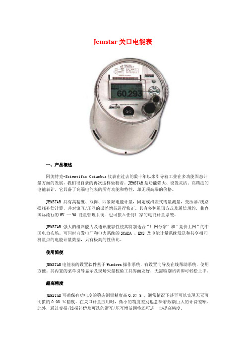
Jemstar关口电能表一、产品概述阿美特克-Scientific Coiumbus仪表在过去的数十年以来引导着工业在多功能固态计量方面的发展,我们很自豪的再次这样做粉着。
JEMSTAR是功能强大、设置灵活、高精度的电能表计,它具备了高端电能表的所有功能和特性,却无须高端的价格。
JEMSTAR 具有高精度、双向、四象限电能计量,固定或滑差式需量测量,变压器/线路损耗补偿计算,并对流互/压互的误差增益进行修正。
具有多种通讯方式及通信规约,兼容国际流行的MV 一90 能量管理系统.也可接入任何厂家的电能计量系统。
JEMSTAR 强大的组网能力及通讯兼容性使其特别适合“厂网分家”和“竞价上网”的中国电力布场。
可同时向发电厂和电力系统的SCADA 、EMS 及电能计量系统发送和共享相同测量点的电能计量数据,只有极高的性价比。
使用简便JEMSTAR电能表的设置软件基于Windows操作系统,有设置向导及在线帮助系统.使用方便。
其内置的菜单引导显示及现场矢量校验工具界面友好,无需特别培训即可轻松上手。
超高精度JEMSTAR可确保有功电度的稳态测量精度高0.07 % ,通常情况下甚至可以实现无无可比拟的0.03 %精度。
在关口计量应用时,微小的精度差别也意味着数额巨大的计费差额。
此外,通过变损/线损补偿及可选的溜互/压互增益调整还可进一步提高精度。
电能质量JEMSTAR 可以基于用户设定的限值记录电压骤升/骤降事件,从而可以确定电力扰动的数量、严重程度及位置等信息。
此外.JEMSTAR还记录电流/电压总谐波畸变THD值、功率因数、不平衡和频率值,使用户可以得到完整的电能质量信息。
现场诊断JEMSTAR恨据预设的限值进行现场诊断,越限情况将自动通知用户。
系统运行状况诊断功能可实现掉电自动回叫主站。
高级通讯通讯方式多样.有RS 一232 , RS 一485,内置调制解调器及光电口。
使用工业标准协议( IEC 870 一5 一102 , DNP3.0 , Modbus RTU 和ASCII, ANSITables 及JEM Binary)可同时以多种方式通信,并兼容MV90 能量管理系统。

e-mail:**************For latest product manuals:User’s GuideCL-355ADry-Block CalibratorShop online at®MADE IN UK-1-SpecificationFigures quoted are at the base of the well at the time of calibration.Temperature range: 5°C/9°F above ambient to 400°C/752°FOver-temperature limit: 450°C/842°F (approximately)Display resolution: 0.1°Accuracy: +/-0.6°C (1.1°F)Stability: +/-0.15°C (0.27°F)Heat up time 20° C to 400°C: 12 minutesCool down 400°C to 100°C: 21 minutesImmersion Depth: 4.5" (114.3mm)Fan Cooling: AutomaticWeight: 9 lbs (4 Kg)Dimensions* (H x W x D): 8.75 x 8 x 8 inches/222.25 x 203.2 x 203.2 mm*excluding the carrying strapElectrical supplyVoltage Cycles Power230V 50/60Hz 900W120V 50/60Hz 900WNote: The above specifications are quoted for an ambient temperature range of 10°C/50°F to 30°C/86°F.Outside this range, the quoted figures may deteriorate but the unit will still work safely.-2-Working environmentThe calibrator units are designed to work safely under the following conditions:Ambient temperature range: 5°C/9°F to 40°C/104°FHumidity: Up to 95% relative humidity, non-condensingWarningWarning: HIGH TEMPERATURES ARE DANGEROUSAvertissement: DANGER DE TEMPERATURES ELEVEESWarnung: HOHE TEMPERATUREN SIND GEFÄHRLICHAviso: LAS TEMPERATURAS ELEVADAS SON PELIHIGH TEMPERATURES ARE DANGEROUS: They can cause serious burns to operators and ignite combustible material. Omega has taken great care in the design of these units to protect operators from hazards, but operators should pay attention to the following points:• USE CARE AND WEAR PROTECTIVE GLOVES TO PROTECT HANDS• DO NOT put hot objects on or near combustible objects• DO NOT operate the unit close to inflammable liquids or gases• DO NOT place any liquid directly in your unit• At all times USE COMMON SENSEOperator SafetyAll operators of Omega Engineering equipment must have available the relevant literature needed to ensure their safety. It is important that only suitably trained personnel operate this equipment in accordance with the instructions contained in this manual and with general safety standards and procedures. If the equipment is used in a manner not specified by Omega, the protection provided by the equipment to the operator may be impaired. All Omega Engineering units have been designed to conform to international safety requirements and are fitted with a preset over-temperature cutout. If a safety problem is encountered, switch off at the mains socket and remove the plug from the supply.-3-Installation1. All Omega units are supplied with a power cable.2. Before connecting the mains supply, check the voltage against the rating plate. Connect the mainscable to a suitable plug according to the table below. Note that the unit must be earth groundedto ensure proper electrical safety.Electrical connections:220V-240V 110V-120VLive Brown BlackNeutral Blue WhiteEarth ground Green/yellow GreenThe fused plug supplied with the mains lead for use in the UK is fitted with the following value fuse to protect the cable: 230V UK 4 AMPThe fuse in the unit protects the unit and the operatorNote that units marked 230V on the rating plate work at 220V; units marked 120V work at 110V. Inboth cases, however, the heating rate will degrade by approximately 8%. The rating plate is on therear of the unit.3. Plug the mains cable into the socket on the rear of the unit.4. Place the unit on a suitable bench or flat workspace, or in a fume cupboard if required, ensuring thatthe air inlet vents on the underside are free from obstruction.After use, when you have finished heating samples, remember that parts of the unit may be very hot.Take the precautions listed earlier.-4-OPERATIONPreparation1.The heater design, temperature sensor and control circuit give good temperature control anduniformity, but make sure that there is a close fit of the probes in the block to allow efficient heattransfer.2. Plug the power cable into the socket in the back of the unit. Connect the mains cable to theelectricity supply.-5-Setting the operating temperature1. To set the temperature required, press and hold the star button and either the up or down buttondepending on the direction you need to take the set point.2. When you have the correct set temperature displayed, release the up or down button and the unitwill start to heat or cool to the set point.3. Once the process value/actual temperature reaches the set point, allow the block to stabilize for 15minutes before performing a calibration.4. The controller is factory pre-set and only the set-temperature should be changed.THE CONTROLLER MUST NOT BE SET TO CONTROL ABOVE 400°C/752°F OR DAMAGE TO THE UNIT MAY RESULT.After use1. When you have finished calibrating, remember that parts of the unit and the probe may be very hot,so precautions should be taken to prevent injury.2.For safety, set the set temperature and allow the unit to cool to below 50°C/122°F before placingthe unit in a carrying case or shipping carton.Changing from °C to °FThe controller is preset to display/operate in degrees C; however it may be changed to read in Degrees F. Refer to the CN9400 User’s guide for instructions on changing from C to °F.Be careful not to change any of the other settings in the configuration menu as performance will be affected and/or damage to the unit will occur!-6-Operator maintenanceNOTE THAT THIS EQUIPMENT SHOULD ONLY BE DISMANTLED BY PROPERLY TRAINED PERSONNEL. REMOVING THE FRONT OR REAR PANELS EXPOSES POTENTIALLY LETHAL MAINS VOLTAGES. THERE ARE NO OPERATOR MAINTAINABLE PARTS WITHIN THE EQUIPMENT.In the unlikely event that you experience any problems with your unit which cannot easily be remedied, you should contact your supplier and return the unit if necessary. Please include any details of the fault observed and remember to return the unit in its original packing. Omega will accept no responsibility for any damage to units that are improperly packed for shipment. If in doubt, contact your supplier. See the Decontamination Certificate supplied with your unit.1.Cleaning: Before cleaning your unit, ALWAYS disconnect it from the power supply and allow it tocool below 50° C. Your unit can be cleaned by wiping with a damp soapy cloth. Care should beexercised to prevent water from running inside the unit. Do not use abrasive cleaners.2.Fuses: Your unit is protected by two fuses. They should only be changed by suitably qualifiedpersonnel. If the fuses blow persistently, a serious fault is indicated and you may need to return theunit to your supplier for repair.ADDITIONAL INFORMATIONThe controller is factory preset. See the Controller book for further details.For safety reasons, the configuration settings of the controller are password protected.Please contact your dealer for further information.Listed below are important control parameters for the unit.Level 1> band=11, int.t =1.5, dEr.t=12, DAC=1.0, Cyc.t=0.3, Bnd.2=15, Cyc.2=20,Level 2 > SP2.A=cool, diSP=0.1, Hi.Sc=400.0, inpt=rtd,Level 3 > SP1.d=SSR, SP3.d=rly-7-Replacement PartsThe following parts may be obtained from Omega Engineering if replacements or alternatives are required: Part Number DescriptionFCABLEUK UK 240 volt Mains cable with 13amp UK plug (5 amp fuse)FCABLEEU Euro style 240 volt Mains cable with R/A Schuko plug7002705 US 120 volt Mains cable7032722 insert extractor7032718 Carrying casePart Number Available inserts Insert well SizesCL701B insert 5 x 1/4”CL702B insert 1 each 1/8”, 3/16”, 1/4”, 5/16”, 3/8”CL703B insert 2 x 1/4” & 2 x 3/8”CL704B insert 2 x 1/4” & 2 x 1/2”CL705B insert 1 x 1/4”CL706B insert blankCL707B insert 1 x 9/16” & 1 x 1/4”CL708B insert 1 x 5/8” & 1 x 1/4”CL709B insert 1 x 11/16” & 1 x 1/4”CL710B insert 1 x 3/4” & 1 x 1/4”Part Number Spare Parts Description7002695 225 watt, 120 volt heater7002697 PRT7002698 Solid state relay7007201 8 amp fuse (120 volt units)6500131 4 amp fuse (240 volt units)-8-FOR WARRANTY RETURNS, please have the following information available BEFORE contacting OMEGA:1.Purchase Order number under which the product was PURCHASED,2.Model and serial number of the product under warranty,and 3.Repair instructions and/or specific problems relative to the product.FOR NON-WARRANTY REPAIRS, consult OMEGA for current repair charges. Have the following information available BEFORE contacting OMEGA:1. Purchase Order number to cover the COST of the repair,2.Model and serial number of the product, and 3.Repair instructions and/or specific problems relative to the product.OMEGA’s policy is to make running changes, not model changes, whenever an improvement is possible. This affords our customers the latest in technology and engineering.OMEGA is a registered trademark of OMEGA ENGINEERING, INC.© Copyright 2010 OMEGA ENGINEERING, INC. All rights reserved. This document may not be copied, photocopied, reproduced, translated,or reduced to any electronic medium or machine-readable form, in whole or in part, without the prior written consent of OMEGA ENGINEERING, INC.WARRANTY/DISCLAIMER OMEGA ENGINEERING, INC. warrants this unit to be free of defects in materials and workmanship for a period of 37 monthsfrom date of purchase. OMEGA’s WARRANTY adds an additional one (1) month grace period to the normal three (3) year product warranty to cover handling and shipping time. This ensures that OMEGA’s customers receive maximum coverage on each product.If the unit malfunctions, it must be returned to the factory for evaluation. OMEGA’s Customer Service Department will issue an Authorized Return (AR) number immediately upon phone or written request. Upon examination by OMEGA, if the unit is found to be defective, it will be repaired or replaced at no charge. OMEGA’s WARRANTY does not apply to defects resulting from any action of the purchaser, including but not limited to mishandling, improper interfacing, operation outside of design limits,improper repair, or unauthorized modification. This WARRANTY is VOID if the unit shows evidence of having been tampered with or shows evidence of having been damaged as a result of excessive corrosion; or current, heat, moisture or vibration;improper specification; misapplication; misuse or other operating conditions outside of OMEGA’s control. Components in which wear is not warranted, include but are not limited to contact points, fuses, and triacs.OMEGA is pleased to offer suggestions on the use of its various products. However, OMEGA neither assumes responsibility for any omissions or errors nor assumes liability for any damages that result from the use of its products in accordance with information provided by OMEGA, either verbal or written. OMEGA warrants only that the parts manufactured by the company will be as specified and free of defects. OMEGA MAKES NO OTHER WARRANTIES OR REPRESENTATIONS OF ANY KIND WHATSOEVER, EXPRESSED OR IMPLIED, EXCEPT THAT OF TITLE, AND ALL IMPLIED WARRANTIES INCLUDING ANY WARRANTY OF MERCHANTABILITY AND FITNESS FORA PARTICULAR PURPOSE ARE HEREBY DISCLAIMED. LIMITATION OF LIABILITY: The remedies of purchaser set forth herein are exclusive, and the total liability of OMEGA with respect to this order, whether based on contract, warranty, negligence, indemnification, strict liability or otherwise, shall not exceed the purchase price of the component upon which liability is based. In no event shall OMEGA be liable for consequential, incidental or special damages.CONDITIONS: Equipment sold by OMEGA is not intended to be used, nor shall it be used: (1) as a “Basic Component” under 10CFR 21 (NRC), used in or with any nuclear installation or activity; or (2) in medical applications or used on humans. Should any Product(s) be used in or with any nuclear installation or activity, medical application, used on humans, or misused in any way,OMEGA assumes no responsibility as set forth in our basic WARRANTY/DISCLAIMER language, and, additionally, purchaser will indemnify OMEGA and hold OMEGA harmless from any liability or damage whatsoever arising out of the use of the Product(s) in such a manner.RETURN REQUESTS /INQUIRIES Direct all warranty and repair requests/inquiries to the OMEGA Customer Service Department. BEFORE RETU RNING ANY PRODUCT(S) TO OMEGA, PURCHASER MUST OBTAIN AN AUTHORIZED RETURN (AR) NUMBER FROM OMEGA’S CUSTOMER SERVICE DEPARTMENT (IN ORDER TO AVOID PROCESSING DELAYS). The assigned AR number should then be marked on the outside of the return package and on any correspondence.The purchaser is responsible for shipping charges, freight, insurance and proper packaging to prevent breakage in transit. It is the policy of OMEGA Engineering, Inc. to comply with all worldwide safety and EMC/EMIregulations that apply. OMEGA is constantly pursuing certification of its products to the EuropeanNew Approach Directives. OMEGA will add the CE mark to every appropriate device uponcertification.The information contained in this document is believed to be correct, but OMEGA Engineering,Inc. accepts no liability for any errors it contains, and reserves the right to alter specificationswithout notice. WARNING: These products are not designed for use in, and should not be usedfor, human applications.M4961/0511。
适用范围本规定适用于干式气密性测试设备的校准。
设备概述干式气密性测试设备是用压缩空气检测零件气密性的专用设备,干式气密性测漏仪原理为差压衰减方式,测试件泄漏时会导致传感器薄膜的偏移。
由于气体的受热膨胀性,要求同一零件的测试温度保持一致。
技术要求压力范围:;检测范围:;设备检测误差:要求&误差<±;校准条件:温度度。
检验项目外观检查;精密压力表检漏设备无需检验;设备的泄漏量的验证标定方法和要求外观目测检查要求:设备应整齐清洁,零部件完整、齐全、油漆完好、无锈蚀,各种仪表正常。
精密压力表需外委标定(检漏设备无需标定)。
作业扌旨导书文件编号:版本日期文件名称:干式气密性测试校准规程设备的泄漏量验证要求:设备上的精密压力表须在标定的时间范围内;验证使用工具:检测仪表;方法:打开电源,接通气源,完成“设备日点检卡”;将设备连接工装的气管拔下,并将其接到检测仪表的接口上。
双手按下启动按钮,调节检测仪表显示值为,待检测时间到后, 记下设备检测值,观察检测值与的差值是否在士范围内,若不在,则需将设备内容积数值调小,然后再启动设备检测,继续比较,若仍然不接近,需要继续减小内容积的设定值,直至检测值与的差值在士以内。
检测仪表分别取值、、、、时,启动设备进行检测并记录下检测值进行比较;判定:计算泄漏量误差6误差V士为合格。
系统的泄漏量验证要求:设备上的精密压力表须在标定的时间范围内;验证使用工具:检测仪表;方法:重复性:评定其重复性指标采用测量能力指数,将全密封样件(即零泄漏样件)在设备上重复安装后测量次,记录每次的测得值然后求值:X(X)式中,——标准偏差采用表格标准公式计算――被测工件的最大允许泄漏量,零件最大允许泄漏量为。
当n时,认为该检测设备的重复性指标符合要求。
精度:检验时:精度评定是利用标准漏块来进行的。
设置个泄漏值测试点,分别为,。
将全密封样件(即零泄漏样件)置于设备上。
在每个评定点等精度地测试次,然后比较检测设备的测得值。
阿美特克JOFRA温度校准仪 ATC-155/ATC-155B ATC-320/ATC-320B ATC-650/ATC-650B操作方法AMETEK Denmark A/S目录一、 设置温度 (2)二、 设置内置标准/外接标准 (2)三、 设置RTD接线方法 (3)四、 设置T/C接线方法 (6)五、 温度与“Ω” 、“mV”转换键……………………….六、自动温度步进测试 (7)七、温度开关测试 (8)八、校准 (10)九、功能键介绍 (12)十、附注 (24)一、 设置温度(SET)1.1 开机按面板上 F1 温度设置键如下图所示。
REFERENCE SENSORREAD: 2 5 . 0 0 ℃SENSOR: ---.---- ------℃SET:NO activateSET temp Calibration SwitchtestAutostepSetup1.2 然后按数字键所设定温度例如:设定50℃按面板上数字键50.00。
1.3 最后按回车键确认即可。
二、(一)设置内置标准2.1 按面板上 F5 键(setup)显示后再按 F5 键(more)显示后按 F2 键(Input)显示后按F1键 Reference 显示后按F1键显示以下图示:REFERENCE SENSOR (标准传感器)Source:Internal reference (内置标准)(READ)ESC .cancel AcceptInternal Reference External Reference按二次回车键确认即可。
显示以下图示:REFERENCE SENSOR READ: 2 5 . 0 0 ℃SENSOR: ---.---- ------℃SET:NO activateSET temp Calibration SwitchtestAutostepSetup(二)设置外接标准2.2 按面板上 F5 键(setup)显示后再按 F5键(more→)显示后按 F2 键(Input)显示后按F1键 Reference 显示后按F2键显示以下图示:Source:External reference sensor(TRUE)Convert to temp : YESSET . follows TRUE:ofESC .cancel AcceptInternal Reference ExternalReferenceConvertto tempSet followTRUE按二次回车键确认即可。
RTC SeriesReference Temperature CalibratorRTC-700Product DescriptionA METEK continues to develop new techniques to improve the performance, accuracy, convenience,and functionality of the popular Jofra calibration products. By doing so, we maintain our position as the leading worldwide manufacturers of temperature dry-block calibrators.We are proud to introduce our new high temperature model RTC (Reference Temperature Calibrator), which is no exception to the above and even more sophisticated than any existing calibrators. Features & ModelsThe RTC offers many new fantastic features such as:⏹ Patented DLC (Dynamic Load Compensation) system for perfect temperature uniformity in the insert.⏹ Unique, intelligent sensors for plug n’ play connection.⏹ USB connector for communication.⏹ Easy-to-read color VGA display with a perfect overview of the actual status.⏹ Intuitive, fast, and user-friendly navigation.⏹ Lightweight and easy to carry around.⏹ New functional carrying case design.⏹ New multi-hole insert kits covering all of the most used sensor sizes.⏹ High profile design and well-known, long lasting Jofra quality.The new RTC calibrator comes in three different models—A, B, and C.⏹ RTC-A reference temperature calibrator.⏹ RTC-B reference temperature calibrator with input for reference sensor, DLC sensor, and sensors-under-test.⏹ RTC-C reference temperature calibrator with input for reference sensor and DLC sensor.Key Features◆High AccuracyDown to ± 0.11°C using the external reference sensor. 4-wire True-Ohm Measurement technology is used.◆Excellent Stability, 0.008°C◆Wide Temperature RangeFrom 33 to 700°C (91 to 1292°F).◆Improved Temperature HomogeneityUnique, active triple-zone block ensures good temperature homogeneity in thecalibration zone.◆DLC (Dynamic Load Compensation)Perfect temperature uniformity in the insert, even when calibrating large sensors or many sensors at a time. (B and C models only.)◆Display Indicator for Temperature UniformityShows the degree of temperature uniformity in the insert when using the new DLCtechnology. (B and C models only.)◆Intelligent Reference SensorsJofra reference sensors are supplied with intelligent plugs, holding the calibration data (coefficients) of the reference sensor. This is a truly plug n’play calibration system.◆USB CommunicationAll RTC calibrators communicate via an easy-to-use USB port.◆Time SavingSuper high-speed cooling.◆EURAMETBest performing dry-block with regard to the EURAMET/cg-13v.01 guideline for thetesting of dry-blocks.DLC –Dynamic Load CompensationTo bring our well documented active dual-zone technology to an even higher level, we have developed the patented DLC system, making it possible to perform top calibration specifications without being affected by the actual load, e.g. many sensors or very big sensors.The RTC-700 adds active triple-zone temperature control.The DLC sensor improves the homogeneity even more, by controlling it not only the well, but inside the insert where the sensors-under-test are placed during calibration. The DLC sensor measures the temperature homogeneity in the insert and provides feedback to the active triple-zone sys-tem, which compensates the temperature difference to a minimum inside the insert. In this way, the DLC function makes the homogeneity indepen-dent of the different loads of the insert, making the RTC the best performing dry-block calibrator on the market when calibrated and tested according to the globally accepted EURAMET/cg-13v.01 guideline for calibration and testing of dryblocks.The DLC system is comprised of a special differential temperature sensor designed especially for the RTC. The sensor is placed in the insert and con-nected to the calibrator. When the DLC function is enabled, the calibrator will automatically equalize the temperature homogeneity inside the insert, along with the normal temperature control and stabilization.SlaveDLCMaster1000.050.100.15Axial Temperature Homogeneity in °CD i s t a n c e t o B o t t o m o f I n s e r t i n m m0.200.25DLC Function On DLC Function O Thermo Sensitive LengthDLC SensorDLC –User AdvantagesCalibrating with the DLC sensor offers the following advantages:1 Calibration of several sensors simultaneously.2 Calibration of thick sensors.3 Gives TSL (Thermo Sensitive Length) independency. It is no longer necessary to know the TLS of the sensor.4 Compensates for sensor production tolerances like the PT100 element being mounted in vari-ous positions in the sensor.5 Trouble free calibration of sensors with PT100 elements up to 60 mm length.6 The DLC indicator proves that the dual-zone is active and functioning well.7 Proves that the calibrator is working perfectly. The DLC value should be very close to 0.00 when the calibrator is loaded with DLC sensor and an external reference sensor.8 Together with the stability indication, the DLC indicates when the calibration values can be read.Axial temperature curves for an RTC calibrator with and without the DLC functionality activated.Unique Triple Zone Temperature PerformanceThe RTC series of calibrators provide precision temperature calibration of sensors, what-ever the type or format. This is accomplished through an innovative active triple-zone heat-ing technology.With the RTC-700’s active triple-zone heating technology, each heating zone is indepen-dently controlled for precision temperature calibration. The homogeneity in the lower part is close to that of a laboratory liquid bath. The lower zone ensures optimum heat dissipa-tion throughout the entire calibration zone. The upper zone compensates for heat loss from the sensor-under-test, and from the open top. This design also eliminates the need for extra insulation of sensors-under-test and makes it possible to calibrate liquid-filled and other mechanical sensors.USB and LAN/Ethernet ConnectionA USB connection facilitates easy communication with JofraCal. The USB connection also sup-ports easy download of future firmware upgrades. The USB connection provides fast and easy access to all laptops without the need of RS-232 to USB converters.Future-proof through e.g. a flash capability for easy firmware upgrades as well as already integrat-ed LAN communication, SD-card slot, and USB host connectors for future use.Intelligent Reference SensorsThe JOFRA STS-200 intelligent reference sen-sors and the DLC sensor contain individual cali-bration data regarding the sensor. Firstly, this means that the time-consuming coefficientdownloading sequence with risk of errors is no longer necessary. Secondly, the user can change the reference sensor and be up and running immediately.With the intelligent sensors, AMETEK has eliminated a source of error, and the system is now giv-ing a fail-safe plug’n’play calibration system.Unique Reference SensorsThe STS-200 reference sensors and the DLC sensors have been specially designed. They are both angled 90˚ and have been customized to fit the calibrator so that they are only slightly higher than the top of the RTC calibrator.The unique design makes it possible to calibrate threaded sensors and sensors with connection heads without any problems.Easy to Carry Only 24.9 lbs/11.3 kgA calibrator is carried from one job to another. Therefore, it is essential that the weight of the calibrator is as low as possible.We have thoroughly included the weight issue in our design and have developed design tech-niques that have made the RTC calibrator lightweight and easy to carry around without compro-mising its quality, durability, and functionality. The purpose of minimizing the weight of the RTC calibrator is to protect, especially frequent users from overload.Long Inserts for Accurate CalibrationThe new extended insert length increases the maximum possible diameter of the sensor under test to 16 mm. Switch tests of long bulb sensors can be carried out with very high accuracy.SetTemperatureInternal ReferenceTemperature Di erenceSensor-Under-TestU p p e r Z o n eM a i n Z o n eWide Temperature Range 700°CThe RTC-700 can perform calibration over a very wide temperature range starting from 33°C and up to 700°C (91 to 1292°F). This makes it possible to perform calibration jobs over a range of 667° C (1232° F) with only one calibrator.Easy to Read Color Display and User-Friendly NavigationThe 5.7" full color VGA display is very easy to read. The main temperatures, like SET, READ, TRUE and SUT (Sensor under test), are always displayed at all stages of the programming or calibration procedure.The navigation is menu-driven and very logical to use, and the display shows any important information needed for the current function in use. The communication windows pop up andare followed by discrete sound messages. The display is very bright, and the main information can easily be read from a distance. The advanced simplicity RTC user interface is available in English, German, Chinese, and Japanese.The large display contains more detailed information at a glance, such as:Up to five temperature readings simultaneously. Stability status.Load compensation status. Real time clock.Serial number of reference sensor. Sensor-under-test status.Fast Temperature CalibrationTime is money! This is why all the RTC calibrators have an increased heating and cooling speed compared to all other calibrators. With its newly developed heating block, the RTC-700 is able to perform a unique combination of high speed and high accuracy, resulting in savings in both production downtime and general calibration costs.Multi-Hole Insert KitsTwo special multi-hole insert kits have been developed to comply with the calibration of almost any sensor diameter without having to buy numerous inserts.The first kit is a metric insert kit consisting of only four inserts covering all diameters from 3 to 13mm. The other is an imperial insert kit consisting of only three inserts covering six different sizes from 1/8" to ½".All inserts have holes for both STS reference sensors and DLC sensors.With this insert kit in the carrying case, the user is now able to calibrate all commonly known sensor sizes. These insert kits are part of the JOFRA lightweight strategy.Special Designed Carrying CaseAMETEK has designed an all-in-one-handle carrying case that makes it possible to store both the STS reference sensors and DLC sensors in the carrying case with optimum physical protection. There is room for inserts and insulation plugs to cover all dimensions and compartments for the integrated support rod set, wires, manuals, certificates, plugs, insert tools etc.All compartments are specially designed to hold one of the above mentioned items. This makes it very easy to keep track of any accessories.For optimum protection of the calibrator and the accessories, the compartments are designed to hold the accessories fixed during transportation.Integrated Support RodThe integrated support rod is part of the reduced weightphilosophy. It is lightweight and very easy to mount onthe RTC. Two fixing holes are integrated in the calibratorwhere the support rods can be mounted. And even thoughits weight has been reduced by 50%, the support rod willremain very firmly positioned.MVI–Secure Temperature StabilityMVI stands for ’’Mains power Variance Im-munity’’. Unstable mains power is a majorcontributor to on-site calibration inaccura-cies. Traditional temperature calibrators oftenbecome unstable in production environ-ments where large electrical motors, heatingelements, and other devices are periodicallycycled on or off. The cycling of supply powercan cause the temperature regulator to per-form inconsistently, leading to both inaccurate readings and unstable temperatures.The JOFRA RTC calibrators all employ the MVI functionality, thus avoiding such stability problems. The MVI functionality is obtained by running the calibrator on stabilized DC voltage.Highest Accuracy (models B & C only)The RTC series calibrators may be supplied with a built-in reference thermometer to be used with an external reference sensor. This feature allows the instrument to perform calibrations on-site, while maintaining high accuracy.A special 90° angled external reference sensor has been designed to accommodate the calibration of sensors with a transmitter head, top connector, or similar arrangement. The user can decide whether to read the built-in reference sensor or the more accurate angled reference sensor from the large, easy-to-read LCD display of the calibrator. The external sensor and the internal sensor readings are independent of one another.SET-Follows-TRUE (models B & C only)Available on B and C models only, the “SET-Follows-TRUE” makes the instrument tune in until the temperature reading of the external reference “TRUE” meets the desired “SET” temperature. This feature is important when it is critical that the temperature of the calibration zone matches the desired temperature when measured with accurate external reference sensors.Reading of Sensor-Under-Test (model B only)Model B of the RTC is equipped with a built-inaccurate measuring circuit for sensor-under-test(input), which enables measurement of virtu-ally any type of temperature sensors including:Resistance thermometers (RTD), thermocouples(TC), transmitters, milliamps (mA), voltage (V) andthermostats.The RTC calibrators can be user-programmed fromthe keyboard for fully automatic sensor calibra-tions. Once the unit is programmed, the instrument is self-operating and performs the configured calibration routine. All calibration data is stored and can be read on the display.Switch Test (model B only)Users may perform a thermoswitch test and find “Open”, “Closed” and the hysteresis (deadband) automatically. The instrument retains the last twenty test results.MVI NORMAL MAINSAuto-SteppingUp to 20 different temperature steps may be pro-grammed including the hold time for each step.Upon completion of an auto-step routine, the usercan easily read the results for the sensor-under-test on the RTC display. Results from twenty auto-step calibrations are stored.The “Set temperature” feature allows the user toset the exact desired temperature with a resolu-tion of 0.001°.Enhanced StabilityA stability indicator shows when the RTC calibrator has reached the desired temperature and is stable. The user may change the stability criteria for the external reference and the sensor-under-test quickly and simply. The stability criterion is the user’s security of a correct calibration. A count-down timer is displayed next to the temperature read-out.Instrument SetupsThe RTC series allows the user to store up to ten (10) complete instrument setups. You may store all sorts of information including temperature units, stability criteria, use of external reference sensors, resolutions, sensors-under-test (SUT), conversions to temperature, display contrasts, etc. The setup may be recalled at any time.Maximum and Minimum TemperatureFrom the setup menu, the user can select the maximum and minimum temperature limit for the calibrator. This function prevents damage to the sensor-under-test caused by excessive tempera-tures, and it helps reducing sensor drift from exposures of too high temperatures. This feature can be locked with an access code.Silent OperationThe RTC calibrator can be programmed to run in silent operation. This function is an advantage if calibrating in a laboratory or in an office. If used in silent operation, the calibrator is not using its full speed potential.As Found/As Left (model B only)When running a calibration initiated from a work order, the user can select the calibration as an As Found or an As Left calibration.Sync OutputA synchronization output signals when the instrument is stable and may be used with ancillary devices such as video recorders, digital cameras or as an input to a data logging device. The SYNC output may be useful for automating and documenting your calibrations when calibrating exter-nal reading devices.Calibration of Indication DevicesWhen calibrating an indicating device in the work order mode, users may key in the results during or after the test. Using the “Calibration info” function, the user may view the complete calibration task, including the “Scenario” before the calibration takes place.JofraCal Hardware RequirementsINTEL™ PENTIUM™ 1.4 GHz processor. 128 MB RAM (256 MB recommended).80 MB free disk space on hard disk (120 MB recommended) prior to installation. USB input device for installation of program. 1 free USB and 1 free RS-232 serial port.Microsoft Windows® XP or Microsoft Windows® Vista. MS San Serif and Arial system fonts.Calibration of Up To 24 Sensors with the Jofra ASM ScannerUsing the JOFRA RTC series together with the ASM, Advanced Signal Multi-scanner, offers a great time-saving automatic solution to calibrate multiple temperature sen-sors at the same time. The ASM series is an eight channel scanner controlled by the JOFRACAL software on a PC. Up to 3 ASM units can be stacked to calibrate up to 24 sen-sors at a time. It can handle signals from 2-, 3- and 4 wire RTD’s, thermocouples, transmitters, temperature switches, and voltage.JofraCal Calibration SoftwareJofraCal is a highly versatile calibration soft-ware that is supplied together with the RTC calibrators. The software ensures easy calibra-tion of all kinds of temperature sensors, such as RTD´s, thermocouples, transmitters, and thermoswithes. Furthermore, it can be used for pressure calibration i.e. pressure gauges and pressure switches. JofraCal integrates with Jofra calibration instruments. As for temperature calibrators, it is the whole rangeof temperature calibrators. Regarding pressure calibrators, it integrates with the Crystal XP2i and nVision. JofraCal also has full integration with the series of signal calibrators.JofraCal may also be used for manual calibrations, as it can be set up to accept manual entry of calibration data together with other liquid baths, ice points, or dry-block heat sources.The calibration data collected can be stored on a PC for later recall or analysis. The RTC calibra-tor stores the calibration procedure and may be taken out to the process site without bringing a personal computer.This allows the RTC calibrator to:Operate as a stand-alone instrument, using advanced calibration routines without the assis-tance of a personal computer on site. The work order functionalityPrevent unauthorized changes to a calibration routine. Personnel who are not authorized toalter a calibration routine cannot do soOnce all calibrations are completed, the data may be uploaded to JOFRACAL for the printing of certificates. The data collected may be stored on the personal computer for later recall or analysis.JOFRACAL offers extended output formats of the captured calibration data such as PDF file format and ASCII/ semicolon separated text format for further processing and calculation of data in spreadsheets and word processors.Multi-Hole Inserts—Metric (mm)All inserts are supplied with an insulation plug drilled with the necessary holes.InstrumentInsert Type Insert Code*RTC-700 (A/B/C)Multi-hole Type 1M01127200Multi-hole Type 2M02127201Multi-hole Type 3M03127202Multi-hole Type 4M04127203Multi-hole Type 7M07127244Multi-hole Type 8M08127245Multi-hole Type 9M09127246Set of 4 Metric Multi Inserts, 3 to 13 mm. (Includes 127203, 127244, 127245, and 127246)SM127252* Use the insert code, when ordering a JOFRA standard multi-hole insert together with the RTC calibrator.1/4"4 mm4 mm 7 mm13 mm1/4" 4 mm4 mm5 mm6 mm3 mm4 mm9 mmInsert Code SMFunctional ComparisonNo part of this document may be reproduced or modified in any form or by any means, electronic or mechanical, without express written permission from Crystal Engineering Corporation.©2021 AMETEK IncorporatedUSA , FloridaTel +1 (800) 527 9999*******************USA , California *Tel +1 (800) 444 1850******************IndiaTel +91 22 2836 4750****************SingaporeTel +65 6484 2388****************China , Shanghai Tel +86 21 5868 5111**********************.cn China , BeijingTel +86 10 8526 2111**********************.cn United KingdomTel +44 (0) 1243 833 302**********************FranceTel +33 (0) 30 68 89 40***********************************GermanyTel +49 (0) 2159 9136 510*********************Denmark *Tel +45 4816 8000*****************ISO 17025 accredited calibration lab.。