SFOC-30说明书
- 格式:pdf
- 大小:394.44 KB
- 文档页数:11

深圳市欧诺克科技有限公司Shenzhen ONKE Technology Co., Ltd.座机:*************27381841电话:邓先生135****7106陈先生139****0920邮箱:***************网 址 : 地址:广东省深圳市宝安区福海街道怀德翠湖工业园13栋稳定的质量是我们赖以生存的根本优质的服务是我们继续发展的前提客户的满意是我们唯一追求的目标产品画册Product gallery专业生产直流无刷驱动器、无刷电机及自动化控制系统深圳市欧诺克科技有限公司直流无刷驱动器目录匠心制造精益求精“一、公司介绍03二、直流无刷驱动器091. 驱动器介绍与型号说明092. BC、BC2无刷系列技术指标113. 驱动器应用领域194. 驱动器外设配件21 0102C O M P A N Y PROFILE以精密制造引领未来Leading the future with precision manufacturing公司简介Company Profile深圳市欧诺克科技有限公司成立于2010年,是一家专业研发生产伺服电机和驱动器的高新技术企业,公司技术力量雄厚,检测手段先进,欧诺克人本着不求最全,只求最精的信念,为生产出各类伺服电机、各类驱动器而不懈奋斗。
欧诺克人以鹰的精神,挑战尖端,生产出性价比的各类伺服电机和驱动器,以鹰的敏锐洞察力洞察市场,随时改进、创新来满足市场的需求。
深圳市欧诺克科技有限公司产品主要有:伺服驱动器、伺服电机、直流伺服驱动器,直流伺服电机,交流伺服驱动器,交流伺服电机,低压伺服驱动器,低压伺服电机,直线电机驱动器,DDR马达驱动器,音圈电机驱动器,直流无刷驱动器,直流无刷电机,Rs485,CANopen总线,EtherCAT总线,电子凸轮伺服系统,大功率伺服驱动器、大电流伺服驱动器,专用伺服驱动器和自动化控制系统,十年来凭借精湛的技术与国内国外众多知名企业公司建立了互利共赢的合作。
` ELECTRONICSF305000A冷水机控制器厂家使用说明书安装使用控制器之前请详细阅读本说明书!2016/03/16软件功能码:X1.AC003A.F30.001-1 V100A2所有翻印必究!目录一、前言 (1)1.1安全要求 (1)1.2 规格说明 (1)二、安装尺寸图 (2)三、电气连接示意图 (4)四、面板示意图 (5)五、操作说明 (5)5.1 密码输入 (5)5.2 参数初始化 (5)5.3 厂家参数设置 (6)5.4 开关机 (6)5.5 控制温度锁定设置 (6)5.6 控制温度设置 (7)5.7 查看电流 (7)5.8 故障界面 (8)六、参数设置 (8)七、能量调节 (10)八、故障代码 (11)附录 (13)一、前言本控制器具有高抗干扰性、功能全面、性价比高等优点,是同类产品中不可多得的优秀控制器。
1.1安全要求1、请务必详尽阅读“安全要求”,并严加遵守各项安全要求。
2、妥善保管好该使用说明书,以便相关人员随时取阅。
3、指定电源为控制器供电,切勿与其它电器或负载共享同一电源,以免导致负荷过大或电源干扰的危险。
4、务必保证控制器可靠接地并经常检查接地是否牢固。
5、安装、布线时请遵守强弱电分离的原则。
6、稳固安装控制器,以防控制器跌落伤人或损坏。
1.2 规格说明二、安装尺寸图图2.1 主板尺寸图图2.2 KEY板尺寸图`Word文档图2.3 铁面板尺寸图三、电气连接示意图注:图中双压机和单压机是指由厂家参数F-20设定的压机个数。
四、面板示意图显示实时温度显示控制温度故障代码对照表通电后亮非停机状态亮有故障时亮压缩机1运行时亮压缩机2运行时亮复位/消音故障开机增加数值/密码移位使能/禁用压缩机1较少数值使能/禁用压缩机2确认/进入/设定停机五、操作说明5.1 密码输入进入密码输入界面后按照图5.1的提示输入正确密码。
闪烁位代表被选中按切换选中位按修改数值按确认密码图5.1 密码输入方法5.2 参数初始化上电后若出现图5.2-1的界面,表示控制器参数错误。
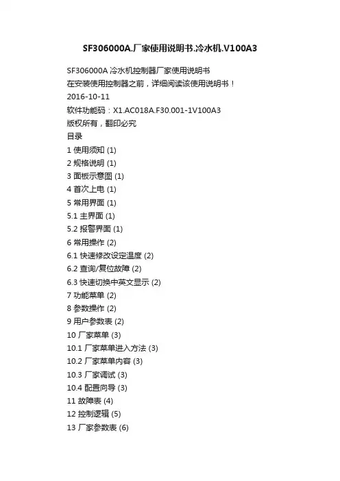
SF306000A.厂家使用说明书.冷水机.V100A3SF306000A冷水机控制器厂家使用说明书在安装使用控制器之前,详细阅读该使用说明书!2016-10-11软件功能码:X1.AC018A.F30.001-1V100A3版权所有,翻印必究目录1 使用须知 (1)2 规格说明 (1)3 面板示意图 (1)4 首次上电 (1)5 常用界面 (1)5.1 主界面 (1)5.2 报警界面 (1)6 常用操作 (2)6.1 快速修改设定温度 (2)6.2 查询/复位故障 (2)6.3快速切换中英文显示 (2)7 功能菜单 (2)8 参数操作 (2)9 用户参数表 (2)10 厂家菜单 (3)10.1 厂家菜单进入方法 (3)10.2 厂家菜单内容 (3)10.3 厂家调试 (3)10.4 配置向导 (3)11 故障表 (4)12 控制逻辑 (5)13 厂家参数表 (6)14 电气连接示意图 (8)15 安装尺寸图 (8)附录 (9)1 使用须知尊敬的客户:感谢您选择了邦普公司的产品!为了方便您的使用,请仔细阅读说明书,并按照说明书的步骤进行操作。
2 规格说明3 面板示意图点亮:允许远程启动/停止熄灭:禁止远程启动/停止闪烁:有故障熄灭:无故障/禁止压机运行功能菜单取消返回移位熄灭:机组停机闪烁:机组正在停机点亮:机组运行起/停机组4 首次上电控制器首次上电需进行配置,具体操作请参考10.4配置向导。
5 常用界面常用界面包括主界面和报警界面。
5.1 主界面5.2 报警界面倒计时完毕后会进入主界面,主界面显示如下:当机组发生故障时,报警提示界面如下:菜单PVFn 闪烁提示报警!℃20.5查询出水温度OK 消音并查询6 常用操作6.1 快速修改设定温度如果用户参数【锁定温度】设置为“否”,主界面下可直接修改设定温度,操作如下:℃注:也可以在用户参数中修改设定温度。
6.2 查询/复位故障发生故障时会自动弹出报警界面,故障查询及复位操作如下:复位OK6.3快速切换中英文显示在主界面下,同时按 3秒后切换显示语言。
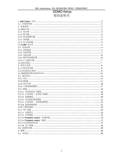
Réf. constructeur : Ed. 03/2004 Réf. GPAO : 33502016501SDMO Kerys使用说明书1. MICS Kerys 介绍 (2)1.1. 目标和结构................................................................................................................................... (2)2. 界面使用 (2)2.1.键盘介绍..................................................................................................................... ... ... ... ... (2)2.1.1 显示器 (3)2.1.2 数字键........................................................................................................................................... (3)2.1.3 发电机操作键............................................................................................................... ......... ... (3)2.1.4 导航键 (3)2.1.5 信号控制键 (3)2.1.6 LED 指示灯 (4)2.2. 界面环境............................................................................................................................ .. (4)2.2.1 屏幕描述 (5)2.2.2 初始屏幕 (5)2.2.3 导航屏幕..................................................................................................................................... (6)2.2.4 操作和设置屏幕..................................................................................................... ... ... ... ... ... (6)2.2.4.1.上边指示器............................................................................................................... ... ......... ... (7)2.2.5保存修改....................................................................................................................... ......... . (7)3. 使用主菜单 (8)3.1.主菜单布局图 (8)3.1.1发电机运行模式 (8)3.1.2根据操作模式的菜单布局 (13)3.2. 操作菜单................................................................................................................................ (14)3.2.1 运行 (15)3.2.2功能键 (15)3.2.3 同步专栏 (16)3.2.4 主要的测量概要.......................................................................................................... ... (17)3.2.5 测量 (18)3.2.5.1. 发电机组电气测量.................................................................................. ... ... ... ... ... (18)3.2.5.2. 汇流母线/ 电网电气测量............................................................................. (19)3.2.5.3. 机械测量...................................................................................................... ......... ... ... ......... (20)3.2.5.4. 发电机组谐波测量................................................................................. ... ... ... ... (21)3.2.5.5. 汇流母线/ 电网谐波测量............................................................................ ... ... ... ... (21)3.2.5.6. 旋转磁场测量..................................................................................................... ............ (22)3.2.6 告警和故障 (23)3.2.7 用户设置 (23)3.2.7.1. 设置要点 (24)3.2.7.2. 功率极限.................................................................................................................... (25)3.2.7.3. Wattmetric control / 常规参量 (25)3.2.7.4. Wattmetric control / 极限............................................................................................. ... (27)3.2.7.5.发电机组优先权......................................................................................................... ... (27)3.2.7.6. 用户参数 (28)3.3. 地域性参数 (29)4. 解释 (30)4.1. 术语表 (30)1. MICS Kerys 介绍1.1. 目标和结构MICS KERYS 系统设计包括一些为测试、控制和设置用的电子模块,及保护油机按照自己的状态或部分按工厂的设置运行。


PD30CTRR60BPxxIO - IO-LinkPhotoelectric Retro-reflective sensors with IO-Link communicationDescriptionThe PD30CTRR60BPxxIO are a part of the latest generation of high performance photoelectric sensors designed to solve most detection tasks due to the new IO-Link features.The sensors are implemented in the compact 10 x 20 x 30 mm ABS housing that are acknoledged world wide.New implemented functions with weight on functionality, reliability, Predictive maintenance make these sensors ideal for Industry 4.0.Benefits• Retro-reflective sensor with IO-Link with a adjustable distance of 1.7 to 6 m, either by trimmer or via IO-Link.• Application functions: Pattern Recognition, Speed & Length, Divider function and Object & Gap Monitoring.• Neighbour Immunity , selectable up to 3 sensors• Easy customization to specific OEM requests by use of the build in IO-Link functionalities.• The output can be operated either as a standard switching output or in IO-Link mode.• Fully configurable via output IO-Link v 1.1. Electrical outputs can be configured as PNP / NPN / Push-Pull / External input, normally open or normally closed.• Timer functions can be set, such as ON-delay, Off-delay, and one shots.• Logging functions: Temperatures, detecting counter, power cycles and operating hours.• Detection modes Single point, two point and windows mode.• Logic functions: AND, OR, XOR and Gated SR-FF.• Analogue output: In IO-Link mode the sensor will generate 16 bit analogue process data output representing various selectable process data such as received signal level.• ApplicationsPattern Recognition : An easy way to verify that a product is manufactured to the specification e.g. Furniture production where tabs or holes has to be with a defined pattern.Speed and Length : Monitor the speed and length of an object on a conveyour for e.g. sorting on size.Divider function : A de-central counting function that gives a signal when a preset count level is reached e.g. when a certain items are packed in a carton box it ask for a new box.Object and Gap Monitoring : Function that can sort out good objects and gaps between them so e.g. a packaging machine only reveive objects with the correct size and gaps.Main functions• Detects presence or absence of objects that cut off the light from the emitter • Detects all opaque objects very reliably• The sensor can be operated in IO-Link mode once connected to an IO-Link master or in standard I/O mode.•Received light intensity as process data.• Neighbor inference protection.• Sensing distance by potentiometer, teach by wire or by IO-link parameter.• Quality of Run and Quality of Teach result.• Temperature date for preventive maintenance.• Front-end check for preventive maintenance.Adjustable parameters via IO-Link interface:• Sensing distance and hysteresis.• Sensing modes: single point or two point or window mode.• Timer functions, e.g.: On-delay, Off delay, One shot leading edge or trailing edge.• Logic functions such as: AND, OR, X-OR and SR-FF.• External input.• Logging functions: Maximum temperatures, minimum temperatures, operating hours, operating cycles, power cycles, minutes above maximum temperature, minutes below minimum temperature, etc.• Auto hysteresis• Special functions: Pattern Recognition, Speed & Length, Divider function and Object & Gap Monitoring. ReferencesProduct selection keyEnter the code option instead ofType selectionStructureCBDA EFCBDA EGFig. 1 CableFig. 2 PlugFig. 3"M8-plug" Pin numbersSensingDetectionApplication functionsPattern RecognitionSpeed and LengthDivider functionObject and Gap MonitoringAlarm settingsDetection diagram0.02.0393.9-2.0795.9-5.9-3.91181581972362763152000300010005000600070008000150400010050-50-100-1500ABCDAccuracyExcess gain0.0 0.4 3.9 39.4393.70.11101001101001000100000.1110100ABCFeaturesPower SupplyAuto adjustInput selectorLogic functionsTime delaysOutputsOperation diagramFor default factory sensor Tv = Power-ON delayResponse timesIndication*See operation diagramLED indicationEnvironmental1)Do not bend the cable in temperatures below-10°C2)With no icing or condensationEMCDiagnostic parametersEvents ConfigurationObservation menuProcess data structure4 Bytes, Analogue value 16 ... 31 (16 bit)Mechanics/electronicsConnectionWiringABHousingDimensionsCompatibility and conformity Approvals and markings(UL508) IO-LinkDelivery contents and accessoriesDelivery contents• Photoelectric switch: PD30CTRR60BPxxIO• Screwdriver• Packaging: Plastic bagAccessories• Mounting bracket: APD30-MB1 or APD30-MB2 to be purchased separately• Connector type: CO..54NF... series to be purchased separatelyFurther informationCOPYRIGHT ©2021Content subject to change. Download the PDF: 。

SF Seriers Pneumatic Actuators SF系列气动阀门驱动装置使用说明书成都麦克斯流体控制有限公司CHENGDU MAX FLOW CONTROL CO.,LTD目录一、概述 (1)二、使用环境条件及应用 (1)三、技术参数 (1)四、安装、配管 (1)五、操作 (2)5-1自动操作方法 (2)5-2 手动操作 (3)六、阀门开、关位置的调节 (4)七、模块结构介绍 (5)八、组装图、零件表 (6)九、模块更换 (7)9-1 弹簧复位气动头由气源故障关变为气源故障开 (7)9-2 弹簧复位气动头由气源故障开变为气源故障关 (7)9-3 双动作型气动头变为弹簧复位气动头 (7)9-4 弹簧复位气动头变为双动作型气动头 (8)9-5 在弹簧模块上安装侧面手轮机构 (8)9-6 在弹簧模块上安液压手动机构 (8)9-7 在弹簧模块上安装开度限位机构 (9)十、注意事项 (9)十一、动作不良时的维修 (9)一、概述本使用说明书适用于SF系列带导向杆的拨叉式气动头,覆盖SF14XXX、SF16XXX、SF25XXX、SF30XXX、SF35XXX、SF40XXX、SF48XXX、SF60XXX各规格的双动作及弹簧复位拨叉式气动头产品,同时适用于SF14XXX、SF16XXX、SF25XXX、SF30XXX、SF35XXX、SF40XXX、SF48XXX、SF60XXX各规格的双动作及弹簧复位拨叉式液动头产品。
二、使用环境条件及应用环境温度:标准型气动头:-20℃~80℃低温型气动头:-40℃~80℃高温型气动头:-20℃~120℃操作压力气动头:3~7 Bar液动头:60~ 150 Bar工作介质气动头:干燥洁净的压缩空气液动头:黏度不大于40CST的液压油,在环境温度较低的地区应使用低温液压油。
产品可作为球阀、蝶阀、旋塞阀、风阀等90°回转阀门的自动驱动装置,广泛适用于化工、食品及饮料、冶金、海洋平台、制药、能源、石油天然气、造纸及纺织等行业。
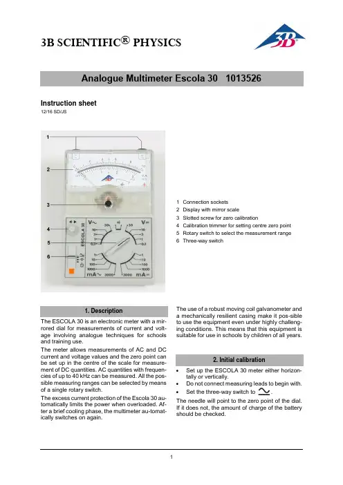
3B SCIENTIFIC® PHYSICSInstruction sheet12/16 SD/JS1 Connection sockets2 Display with mirror scale3 Slotted screw for zero calibration4 Calibration trimmer for setting centre zero point5Rotary switch to select the measurement range6 Three-way switchThe ESCOLA 30 is an electronic meter with a mir-rored dial for measurements of current and volt-age involving analogue techniques for schools and training use.The meter allows measurements of AC and DC current and voltage values and the zero point can be set up in the centre of the scale for measure-ment of DC quantities. AC quantities with frequen-cies of up to 40 kHz can be measured. All the pos-sible measuring ranges can be selected by means of a single rotary switch.The excess current protection of the Escola 30 au-tomatically limits the power when overloaded. Af-ter a brief cooling phase, the multimeter au-tomat-ically switches on again. The use of a robust moving coil galvanometer and a mechanically resilient casing make it pos-sibleto use the equipment even under highly challeng-ing conditions. This means that this equipment is suitable for use in schools by children of all years.∙Set up the ESCOLA 30 meter either horizon-tally or vertically.∙Do not connect measuring leads to begin with. ∙Set the three-way switch to .The needle will point to the zero point of the dial. If it does not, the amount of charge of the battery should be checked.The analogue multimeter Escola 30 conforms tosafety regulations for electrical measurement, con-trol and laboratory equipment, as specified in DIN EN 61010-1, protection class 2 and to measuring category CAT I for up to 30 V. It is not approved for measurements on low-voltage distribution equip-ment, such as sock-ets, fuses, etc. The nominal voltage must not exceed 30 V.The meter is intended for measurements within its measuring ranges and in a measuring environ-ment as described in detail in the course of this manual. Safe operation of the multimeter is guar-anteed if it is solely used as specified. Safety can-not be guaranteed, however, if the multimeter is used incorrectly or handled without due care and attention. In order to avoid serious injury due to cur-rent or voltage shocks, the following safety instruc-tions are to be observed at all times:∙Carefully read the instruction manual before using the multimeter and obey the instruc-tions therein.The assumption needs to be made that unfore-seen voltages may be present in the vincinity of objects being measured (e.g. faulty equipment). ∙Before using the multimeter, check the hous-ing and measuring leads for damage and if there should be any malfunctions or visible damage, the multimeter is not to be used. Pay specific attention to the insulation for the measuring sockets.∙The authorised measuring range is not to be exceeded. If measurements are made when the magnitude of the variable is unknown, al-ways select a large measuring range before shifting down to lower ones.∙Before using the analogue multimeter to check that a voltage source is not exhibiting any actual voltage, check that the meter is working properly by selecting the battery test function.∙When measuring current, make sure the elec-tricity is turned off before the analogue multi-meter is connected into the circuit.∙When making measurements, always con-nect the ground lead first. Disconnect the sig-nal measurement lead before unplugging the ground.∙Turn off the multimeter before opening the casing, disconnect the power to the circuit and the measuring leads from the multimeter.∙When the multimeter is used by teenagers, trainees etc., a suitable person should super-vise to ensure the equipment is used safely.4.1 To switch on:∙4.2 Checking battery charge:∙∙Disconnect all measuring leads.∙placed immediately.4.3 Zero point calibration:∙Set up the analogue multimeter either hori-zontally or vertically∙∙Turn the rotary switch to 30 V=.∙Connect the sockets together with a short connecting lead.∙Turn the zero-point trimmer screw to adjust the zero point as needed.4.4 Zero point calibrationfor centre zero point:For measurements of DC current and voltage, thezero point of the scale can be moved to the centre of the dial.∙Disconnect all measuring leads.∙∙Use the zero-point trimmer to line up the nee-dle precisely in the centre of the dial.4.5 To switch off:∙When the meter is turned off, the needle points to .4.6 If a measurement is interrupted by batterycut-out:After 45 minutes of use, the multimeter is auto-matically shut off and the needle will then point to .To switch back on:∙Set the three-way switch of the analogue mul-timeter to off and then use it to turn the meter back on.∙ Connect the side with the lower potential to the left-hand socket.∙Connect the common/ground lead first and only then the signal lead.5.1 DC currents (mA=):∙ Set the rotary switch to the desired DC currentrange. If measurements are made when the magnitude of the variable is unknown, always select a large measuring range before shifting down to lower ones.∙Set the three-way switch5.2 AC currents (mA~):∙ Set the rotary switch to the desired AC currentrange. If measurements are made when the magnitude of the variable is unknown, always select a large measuring range before shifting down to lower ones.∙∙ Connect the side with the lower potential to the left-hand socket.∙Connect the common/ground lead first and only then the signal lead.6.1 DC voltages (V=):∙ Set the rotary switch to the desired DC voltagerange.If measurements are made when the magnitude of the variable is unknown, always select a large measuring range before shifting down to lower ones.∙Set the three-way switch6.2 AC voltages (V~):∙ Set the rotary switch to the desired AC voltagerange.If measurements are made when the magnitude of the variable is unknown, always select a large measuring range before shifting down to lower ones.∙Symbols for measuring ranges~~~~~~~~Display:Scales: 0 … 10, linear0 … 3, linearType: Mirror scaleScale length: 80 mmPointer deflection: 0…90°Electricalzero-point offset: in all DC rangesMeasurements:Voltage ranges: 0.3, 1, 3, 10, 30 V AC/DC Internal resistance: 10 k /VCurrent ranges: 1, 10, 100, 1000,3000 mA AC/DC Voltage drop whenmeasuring current: 100 mV approx. AC/DCReference conditions:Ambient temperature: 23 °COperating alignment: Vertical/horizontal Signal form: Sine (1% max. discrep-ancy)Peak factor:Frequency range: 40 Hz … 50 Hz … 5 kHzAccuracy (at reference conditions):DC quantities: Class 2DC withzero-point offset: Class 5AC quantities: Class 3Extended frequency range (class 10):0.3 – 30 V: 40 Hz … 50 Hz … 40 kHz1 – 3000 mA: 40 Hz … 50 Hz … 40 kHzOverload protection:Current and voltage ranges:reversible for up to ±50 V AC/DC peak-to-peak value and max. 40 A.Electrical safety:Safety specifications: EN 61010-1 Measuring category: CAT I: 30 V Contamination level: 2Protection type: IP20Connectors: 4-mm safety sockets Power supply:Battery: 1x 1.5 V, AA IEC LR6 Automatic cut-off after: 45 min ± 10 minElectromagnetic compatibility:Interference emission: EN 55011:2009 Interference resistance: EN 61326-1:2013Operating conditions:Ambient temperature: 5 °C ... 23 °C … 40°C Storage temperature: -20 … 70°CRelative humidity: <85% with no condensa-tionGeneral data:Shock test: max. 147 m/s² Dimensions: 100x150x50 mm3 ap-prox.Weight: 300 g approx.. Measuring categories according to DIN EN61010-1.CAT I or unstipulated: Approved for measure-ments in circuits which are not directly connected to the low voltage mains grid (e.g. batteries). CAT II: Approved for measurements in circuits which are directly connected, by a mains lead and plug for instance, to the low voltage mains grid (e.g. household or office appliance and lab equip-ment).CAT III: Approved for measurements in circuits which are part of a building’s wiring installation (e.g. stationary consumers, distribution terminals, appliances connected directly to the distribution box).CAT IV: Approved for measurements in circuits which are directly connected to the source of the low voltage mains (e.g. electricity meters, main service feed, primary excess voltage protection).10.1 Battery testing:Batteries which are discharged and have not been used for a while may leak.10.2 Changing the battery:The polarity is indicated by plus and minus signs inside the fuse holder compartment. A mechanical system ensures the battery makes no contact if it is inserted the wrong way round.∙ Unscrew the back of the casing.∙ Replace flat batteries with 1.5-V alkaline bat-teries of size AA IEC LR6.∙ Place the negative pole of the battery on thespring.∙ Close casing again.10.3 Cleaning:∙ For cleaning, use a soft cloth, slightly mois-tened with alcohol, or a brush.Electrostatic charging of the display window can affect the measurements under certain circum-stances:∙ To remove such charge, use a soft clothslightly soaked in alcohol or a paint brush. Dirt or moisture in the measurement sockets can affect readings.∙ Shake out any dirt that may be in the meas-urement sockets.∙ Soak a new swab with isopropyl alcohol andwork around the inside of each measurement socket. ∙ The packaging should be disposed of at local recycling points.∙Should you need to dis-pose of the equipment itself, never throw it away in normal domes-tic waste. If being used in private households itcan be disposed of atthe local public waste disposal authority.∙ Comply with the applicable regulations for the disposal of electrical equipment.∙Do not dispose of the batteries in the regular household garbage. Follow the applicable le-gal regulations (UK: Waste Batteries and Ac-cumulators Regulations, EU: 2006/66/EC).。
SF Seriers Pneumatic Actuators SF系列气动阀门驱动装置使用说明书成都麦克斯流体控制有限公司CHENGDU MAX FLOW CONTROL CO.,LTD目录一、概述 (1)二、使用环境条件及应用 (1)三、技术参数 (1)四、安装、配管 (1)五、操作 (2)5-1自动操作方法 (2)5-2 手动操作 (3)六、阀门开、关位置的调节 (4)七、模块结构介绍 (5)八、组装图、零件表 (6)九、模块更换 (7)9-1 弹簧复位气动头由气源故障关变为气源故障开 (7)9-2 弹簧复位气动头由气源故障开变为气源故障关 (7)9-3 双动作型气动头变为弹簧复位气动头 (7)9-4 弹簧复位气动头变为双动作型气动头 (8)9-5 在弹簧模块上安装侧面手轮机构 (8)9-6 在弹簧模块上安液压手动机构 (8)9-7 在弹簧模块上安装开度限位机构 (9)十、注意事项 (9)十一、动作不良时的维修 (9)一、概述本使用说明书适用于SF系列带导向杆的拨叉式气动头,覆盖SF14XXX、SF16XXX、SF25XXX、SF30XXX、SF35XXX、SF40XXX、SF48XXX、SF60XXX各规格的双动作及弹簧复位拨叉式气动头产品,同时适用于SF14XXX、SF16XXX、SF25XXX、SF30XXX、SF35XXX、SF40XXX、SF48XXX、SF60XXX各规格的双动作及弹簧复位拨叉式液动头产品。
二、使用环境条件及应用环境温度:标准型气动头:-20℃~80℃低温型气动头:-40℃~80℃高温型气动头:-20℃~120℃操作压力气动头:3~7 Bar液动头:60~ 150 Bar工作介质气动头:干燥洁净的压缩空气液动头:黏度不大于40CST的液压油,在环境温度较低的地区应使用低温液压油。
产品可作为球阀、蝶阀、旋塞阀、风阀等90°回转阀门的自动驱动装置,广泛适用于化工、食品及饮料、冶金、海洋平台、制药、能源、石油天然气、造纸及纺织等行业。
EXCM-30说明机械安装80292921306NH [8025435]平面门架EXCM-302Festo –GDCE-EXCM-30-ZH –1306NH –中文原版操作手册的译本GDCE-EXCM-30-ZH危险标识和避免危险的提示:警告可能造成重大伤亡的危险。
小心可能造成轻伤或严重财产损失的危险。
其它符号:注意财产损失或功能丧失。
其它文件中的建议、提示、参考。
必需或适用的附件。
环保使用说明。
文本标记:•可按任意顺序进行的工作。
1.应按规定顺序进行的工作。
–一般列举项。
EXCM-30Festo –GDCE-EXCM-30-ZH –1306NH –中文3目录–EXCM-301产品使用的安全和前提条件5................................................1.1安全5....................................................................1.1.1一般安全提示5....................................................1.1.2按规定使用5.....................................................1.2产品使用前提条件6........................................................1.2.1技术方面的前提条件6..............................................1.2.2专业人员的资质6..................................................1.2.3应用范围及认证6..................................................2运输和存放7..............................................................2.1存放条件7................................................................2.2检查供货范围7............................................................3概要8....................................................................3.1特征8....................................................................3.1.1马达的安装位置9..................................................3.2功能和应用10..............................................................3.3作用原理10................................................................3.4结构11....................................................................3.4.1马达EXCM-30-…-B …的安装位置11...................................3.4.2马达EXCM-30-…-T …的安装位置12...................................3.5马达13....................................................................3.5.1安装选项13.......................................................3.5.2马达派生型13.....................................................3.6接口14....................................................................3.6.1马达接口14.......................................................3.6.2控制器接口14.....................................................4装配和安装15..............................................................4.1安装准备15................................................................4.1.1安装位置15.......................................................4.1.2安装面要求15.....................................................4.1.3尺寸EXCM-30-…-B …16..............................................4.1.4尺寸EXCM-30-…-T …17..............................................4.1.5型材安装件的数量18................................................4.1.6型材安装件的安装孔19..............................................4.2平面门架的安装20..........................................................4.2.1型材安装件的使用20................................................4.2.2安装件21.........................................................EXCM-304Festo –GDCE-EXCM-30-ZH –1306NH –中文4.3附加元件和附件23..........................................................4.3.1附加元件的安装23..................................................4.3.2调整Y 轴的限位挡块24.............................................4.4马达连接25................................................................4.4.1安装原理25.......................................................4.4.2外购马达26.......................................................4.5安装26....................................................................4.5.1连接马达电缆和编码器电缆26........................................4.5.2传感器的安装26....................................................4.5.3调整马达电缆引线的位置27..........................................5调试29....................................................................6维护和保养30..............................................................6.1清洁30....................................................................6.2润滑31....................................................................7拆卸和维修32..............................................................7.1拆卸32....................................................................7.2维修32....................................................................7.3附件32....................................................................7.4报废处理32................................................................A 技术性附录33..............................................................A.1技术参数33................................................................A.1.1一般参数33.......................................................A.1.2认证33...........................................................A.1.3材料33...........................................................A.1.4产品重量34.......................................................A.1.5动态参数(EXCM-30-…-ST 或EXCM-30-…-SB)34.......................A.1.6工作和环境条件35..................................................1产品使用的安全和前提条件Festo –GDCE-EXCM-30-ZH –1306NH –中文51产品使用的安全和前提条件1.1安全1.1.1一般安全提示•请您遵守相应章节的一般安全提示。
SF-HC30P割炬高度控制器北京斯达峰控制技术有限公司北京市石景山区海特花园44号楼206目录1前言 (1)1.1 目的 (2)1.2 重要声明 (2)1.3 警告 (3)2概述 (4)2.1技术特点 (4)2.2功能特点 (5)2.3 主要技术指标 (6)3安装 (7)3.1 安装 (7)3.2接口定义说明 (8)4参数说明 (12)4.1参数设定说明 (12)4.2增强参数说明 (12)5使用指南 (14)5.1手动操作 (14)5.2自动操作 (15)6数控系统与调高器有关M指令 (16)6.1 数控系统直接控制输出端口的M功能 (16)6.2 M功能固定循环 (16)6.3 数控系统推荐设置(斯达峰系统) (17)7故障排除 (18)8附录 (19)9联系我们 (20)1前言无论是火焰切割还是等离子切割方式,在切割过程中割炬的割嘴与割板之间的距离(高度)的稳定性至关重要,它将直接影响到切割的速度和切口的质量。
SF-HC30P等离子割炬高度控制器1.1 目的SF-HC30P等离子割炬高度控制器是专门为等离子坡口切割机设计的割炬高度自动控制模块。
SF-HC30P等离子割炬高度控制器操作简单,调试方便,价格实惠,采用全数字控制,性能可靠。
是焊割设备厂家的理想的配套产品。
1.2 重要声明l SF-HC30P等离子坡口割炬高度控制器实物和使用手册内容可能存在部分差异,请以实物为准。
以后本产品或其附件有任何修改,恕不另行通知。
l请务必阅读安全警告和注意事项,以免不当使用导致危险事故。
l安装使用本产品之前,必须严格按照本产品系统手册的详细说明进行操作,以确保正确使用产品。
l关于SF-HC30P等离子坡口割炬高度控制器及本手册的内容,若被进行任何特定的非法使用,不代表本公司的立场,并拒绝承认其法律责任,一切后果由使用者承担。
l安全警告事项是用来防止人体和财产的伤害。
l在使用SF-HC30P坡口割炬高度控制器过程中,如若发生任何产品质量问题,消费者可以致电本公司产品服务中心或授权办事处、经销商、代理商处获得相应的产品服务。
30"DUAL-FUEL FREESTANDING RANGE MODELS:KFDC500JSS01(Stainless)Illus.No.Part No.Description1Literature PartsW11114331Guide,Use And CareW11114334Instructions,InstallationW11184759Guide,InternetConnectivityW11202391Diagram,Wiring(Cooktop)W11202385Diagram,Wiring(Oven)W11202289Sheet,TechW11114332Guide,Quick Start Illus.No.Part No.Description2W10892994Assembly,ValveManifold(Left Front,Left Rear)W10892997Assembly,ValveManifold(Right Front,RightRear)3W10903728Switch,Harness4W11121194Bracket,Manifold5W11121317Module,Spark64453116Adapter,Male77101P426-60Screw8W10892281Tube,Manifold Supply(Left)W10892292Tube,Manifold Supply(Right)9Box,Burner(NotServiced)Illus.No.Part No.Description10W10115843Cover,Ignition11W11121361Filler,CooktopFOLLOWING PARTSNOT ILLUSTRATEDW11200301Harness,Main(30")W11200328Harness,CooktopW10780278Harness,Door LockW11200325Harness,CommunicationW11242785Harness,WIFIW11212216Cord,Power9759877Retainer,Strain ReliefW10253333Bracket,Anti-Tip7101P485-60Screw,Anti-Tip KitW11238042Kit,LP ConversionIllus.No.Part No.Description1W11106881Panel,Cabinet Side(Left)W11106880Panel,Cabinet Side(Right)2W10892774Assembly,OrificeHolder(Left Front)W10892484Assembly,OrificeHolder(Left Rear)W10892479Assembly,OrificeHolder(Right Front)W10892735Assembly,OrificeHolder(Right Rear)3W10892422Orifice,Main(17.4K)(Left Front,RightFront)W10892419Orifice,Main(15K)(Left Rear)W10892435Orifice,Simmer(2.6K)(Left Front,RightFront)W10892438Orifice,Simmer(5K)(Right Rear)4W11238757Igniter(Left Front,RightFront)W10892340Igniter(Left Rear)W11114379Igniter(Right Rear)Illus.No.Part No.Description5W11291183Burner,Grate(WithWok Ring)6W11291179Burner,Grate7W11323261Screw(8-18X1")W11323309Screw(8-18X1/2")8W11281269Barrier,ApplianceManager9W11436334Interface,User10W11205795Cover,WIFI Outer11W10883433Bezel(Rear Burners)12W10881642Bezel(Front Burners)13Cap,BurnerW11121389Black(Set Of4)14W10891746Spreader,Flame(High)(Left Front,RightFront)W10891974Spreader,Flame(Low)(Left Rear)W10891978Spreader,Flame(AUX)(Right Rear)15W11036559Spring Clip,Range16Knob,Oven ModeW11249667Stainless17W11100279Manager,Appliance(Powermax)18Panel,CooktopW11038235Black(Left)W11038245Black(Right)Illus.No.Part No.Description19W11130078Antenna,WIFI20W10568405Assembly,Speaker21W10130760Bracket,MovingConsole(Left)W10130759Bracket,MovingConsole(Right)22W11328357Screw23W10877949Panel,Console24Knob,SingleW10912166Stainless25Knob,DualW10883172Stainless26W10896366Assembly,Light Pipe27Bezel,OvenW10913810Stainless28Knob,OvenTemperatureW11429269Stainless29W11205794Cover,WIFI Inner30W11241511Button Assembly,Oven Light31W11156414Trim,Island32Trim,T-StripW10271524Black337101P426-60Screw34W11241510Button Assembly,Oven Start353400814Screw36W11291178Kit,Grate Filler37W11042504Bumper,Grate38W11110768Assembly,WIFIModule397101P624-60ScrewIllus.No.Part No.Description1W11394773Kickplate2W11324989Back,Chassis3W10138054Assembly,Roller4W11109583Duct,Bottom(30")57101P426-60Screw69760860Leveler7W10908710Base,Leveling Leg84449743Screw9W11369237Cabinet,ApplianceManager10W10115869Shaft,Long Illus.No.Part No.Description11W10115793Shaft,Short12489504E-Ring13W11106963Tube,PressureRegulator14W11087491Support,Channel15W11115328Gasket,Oven(30")16W11050145Duct-Chassis,Rear17W11368831Channel,Wire18W11362015Retainer,Gasket(9"Long)19W11324986Top,Chassis20W11040802Chassis,BottomIllus.No.Part No.Description21W11103334Panel,Back Top22W11034134Panel,Back Bottom23W11096823Bracket,PressureRegulator24W10449140Regulator,Pressure25W11036559Spring Clip,Range26W11106341Drawer,ApplianceManager27W11199181Cover,Foot(Left)W11199178Cover,Foot(Right)28W10919715GasketIllus.No.Part No.Description14449751Thermostat(TOD)2W10622170Probe,Sensor3W10351278Bumper&Screw4W10830016Latch,Motorized5W11290663Tube,Vent6W10169756Lens,Light7W11223932Assembly,Oven Light8W10169757Bulb,Light9W11096294Receiver,Hinge(Left)Illus.No.Part No.Description10W11096293Receiver,Hinge(Right)11Liner,Oven(NotServiced)12W11102297Chassis,Side(Left)W11102296Chassis,Side(Right)137101P426-60Screw14W10160858Cover,LatchIllus.No.Part No.Description153196176Screw16W11192755Frame,FrontFOLLOWING PARTSNOT ILLUSTRATEDW10282810Insulation,Wrap,30"W10282818Insulation,Back,30"3400968NutVENTING PARTSVENTING PARTSIllus.No.Part No.Description1W10818234Slope,Exhaust Vent(30")2W11105223Vent,Cooling Top(30")3W11200129Blower4W11105222Vent,Cooling Bottom(30")Illus.No.Part No.Description5W11109518Plate,Cooling Latch6W11353392Box,Terminal77101P426-60Screw8W11047754Bracket,Blower Mount9W10270397Seal,Vent Slope(30")Illus.No.Part No.Description10W10270396Seal,Chimney119761958Block,Terminal12112432Nut,Hex13W11106956Cover,ChannelIllus.No.Part No.Description1W11036771Liner,Door2W11413190Insulation,Door(30")3W11184409Glass,Inner4W11194821Retainer,Glass5W11390105Hinge,Door(Left)6W11390124Hinge,Dual(Right)Illus.No.Part No.Description7W10272594Frame,Glass8W10898280Screw9W10656499Screw10W11389280Assembly,Outer Door(Includes Handle)11W11362707Handle Assembly,DoorIllus.No.Part No.Description12W11197830Bracket,Handle13W10518672Badge14W10276043Screw15W11361073Medallion,Handle16W10162096Screw17W10607120ScrewIllus.No.Part No.Description1W10115994Element,Broil2W10282821Insulation,ConvectionCover3W10570887Rack,Oven4W11108461Rack,Oven(Sliding)5W10160856Shield,Element Broil6W11212180Baffle,Convection7W10722667Fan,Convection8W10631503Blade,Fan Illus.No.Part No.Description9W10261523Plate,Fan10W10631504Nut,Acorn(LH)119762242Element,ConvectionSteam12W11109421Tray,Hidden Bake139755542Probe,Temperature144449154Screw159755543Jack,Meat Probe16W11033111Nut,LockingIllus.No.Part No.Description17W10739592Screw18W10115995Element,Hidden Bake19W10720084ScrewOPTIONAL PARTS(NOT INCLUDED) Illus.No.Part No.DescriptionACCESSORY PARTS4396920Stainless SteelCleaner&PolishW10160195Cover,Grill/GriddleW10216179Ring,WokBacksplashW1028544948"With Shelves31464Cleaner,CooktopW10123240Rack,Broiler Pan&Roasting8284755Backsplash(Adjustable)JXA9001CDPStainless SteelWallsplashW11238043Kit,High AltitudeMedallion,HandleW11368841SI.SilverW11368841BO.Black ANOW11368841RE.Red ANOW11368841MP.Marscapone(Cream)W11368841NE.New GoldW11368841CF.CopperW11368841BN.BronzeW11368841DD.Dark Blue。
Rheology Systems for Melt Flow Testers MF20 and MF30Thermoplastic materials are processed as fluids under the effect of temperature and pressure. The ability of melted materials to flow under pressure at set temperatures has a fundamental importance in polymer science and technology. The Instron® line of CEAST Melt Flow Testers are specifically designed for the easy and accurate measuring of the flow properties of plastics according to the relevant ISO and ASTM international standards.The renewed line of CEAST melt flow testers includes four different models: MF10, MF20, MF30, and MF50. These range from manual determination of MFR (melt flow rate) to semi-automated MVR (melt volume rate) measurements involving multiple weight testsThe versatile CEAST MF20 and MF30 are single-weight systems that are ideal for performing tests according to ISO 1133 and ASTM D1238 Procedures A, B, and C. Compliant with ISO 1133-2 requirements, they can perform reliable tests on commodity materials, as well as on the most temperature- and moisture-sensitive special grade materials. Many different options are available: from primary test inspection to integrated test automation solutions.CEAST MF20The CEAST MF20 is offered as a basic machine to beconfigured with a variety of options. You can add ahigh-resolution digital encoder (for MVR measurementas per Procedure B and C), manual or motorized meltcutting devices for accurate melt density determination,and a motorized weight lifter. By choosing the new ManualMass Selector, you can keep a series of 8 test massesinstalled and available at all times, allowing you to andquickly select the desired one for your test – no handlingof masses!CEAST MF30The CEAST MF30 includes a high-resolution digitalencoder and an N/C controlled weight lifter. The lifteris equipped with an integrated load cell for controlledcompacting and purging operations; a significantimprovement for repeatability and time savings (notavailable for MF20). The machine can be equipped withManual Mass Selector, melt cutting devices, and all theadditional options of the MF20.2Rheology Systems | Melt Flow Testers MF20 and MF30Manual mass selectorCEAST MF20 and MF30 – Options• High-precision encoder to measure MVR (included with MF30)• Quick and accurate lifter for automatic test mass application (included with MF30)• Manual Mass Selector to avoid heavy mass handling and configuration changes• Die plugging device to prevent material flowing during pre-heating• Go/No-go gauges for die tolerance check• Nitrogen blanket device for hygroscopic materials testing • Acid-resistant version for chemically aggressive materials • Manual or motorized cutting device of extrudate • Integrated device for automatic barrel cleaning • CEAST VisualMelt Software for storage and analysis ofresults with graphical capabilitiesThe New Manual Mass Selector OptionAvailable for CEAST MF20 and MF30, the integrated Manual Mass Selector simplifies the configuration and testing, and ensures outstanding operator safety. With minimal physical effort, there is no heavy mass handling required and the configuration of the machine always remains the same. The standard set of masses enables the following test conditions: 0.325 (mass of piston) – 1.2 – 2.16 – 3.8 – 5 – 10 – 15 – 21.6 kg (masses tolerance ±0,5% according tointernational standards, with extremely easy checking and costless maintenance).• Masses remain installed at all times on the support; custom sets of masses are available on request• The device features a series of mechanical and electrical solutions to prevent hazardous situations and ensure trouble-free operation• Requires Weight Lifter (optional for MF20, included for MF30)• Doesn’t require compressed air supply Features and Benefits• Ergonomic and compact design for easy and safe testing, service, and maintenance • High-temperature accuracy and stabilityaccording to ISO 1133-2• Easy-to-operate, on-board interface for accurate test execution• MVR with up to 40 data points acquisition for a single test (with encoder)• Wide range of masses designed for all material testing: from fast-flowing masterbatches up to highly viscous rubbery or filled materials• Guided piston design for accurate positioning into the barrel • Standard tungsten carbide and special dies for specific standards• Quick die release and locking mechanism• Load cell for controlled material compacting and purging (only on MF30)• Robust mechanical design, modularity of options to tailor and upgrade your system MF203Instron is a registered trademark of Illinois Tool Works Inc. (ITW). Other names, logos, icons and marks identifying Instron products and services referenced herein are trademarks of ITW and may not be used without the prior written permission of ITW. Other product and company names listed are trademarks or trade names of their respective companies. Copyright © 2013 Illinois Tool Works Inc. All rights reserved. All of the specifications shown in this document are subject to change without notice.POD_MeltFlowTestersMF20andMF30_rev1_0912Worldwide Headquarters825 University Ave, Norwood, MA 02062-2643, USA Tel: +1 800 564 8378 or +1 781 575 5000European HeadquartersCoronation Road, High Wycombe, Bucks HP12 3SY, UK Tel: +44 1494 464646CEAST HeadquartersVia Airauda 12, 10044 Pianezza TO, Italy Tel: +39 011 968 5511Die Plug and manual cuttingDigital encoder。
SpecificationsCONTACT RATING: See individual parts.MECHANICAL & ELECTRICAL LIFE: 10,000 cycles.CONTACT RESISTANCE: 20 m Ω or less.INSULATION RESISTANCE: 100 M Ω min. at 500 VDC.DIELECTRIC STRENGTH: 500 VAC for 1 minute.OPERATING TEMPERATURE: –30ºC to +70ºC.PACKAGING: Bulk* For RoHS compatible switches contact customer service.BASE: Phenolic resin.ACTUATOR: Standard: POM, Black. High Temperature Option: PA46, Black.HOUSING: SPCC Sn plated.MOVABLE CONTACT: Copper alloy, silver plated.STATIONARY CONTACTS: Brass, silver plated.TERMINALS: Brass, silver plated.TERMINAL SEALED.NOTE: Specifications and materials listed above are for switches with standard options. For information on specific and custom switches, consult Customer Service Center.How To OrderPart number list is shown below. For individual part details, please refer to the following pages.Part Number (Part Description)Product DetailsOS102011MS2QN1SPDT, 2mm travel, Vertical, PC Thru-hole, Frame H=4.7mm, Tail L=2.8mm, Non shorting OS102011MS2QN1C SPDT, 2mm travel, Vertical, PC Thru-hole, Frame H=4.7mm, Tail L=2.8mm, Non shorting, High temperature resinOS102011MS2QS1SPDT, 2mm travel, Vertical, PC Thru-hole, Frame H=4.7mm, Tail L=2.8mm, Shorting OS102011MS2QS1C SPDT, 2mm travel, Vertical, PC Thru-hole, Frame H=4.7mm, Tail L=2.8mm, shorting, High temperature resinOS103011MS8QP1SP3T, 2mm travel, Vertical, PC Thru-hole, Frame H=4.7mm, Tail L=3.8mm, Not specified OS103011MS8QP1C SP3T, 2mm travel, Vertical, PC Thru-hole, Frame H=4.7mm, Tail L=3.8mm, Not specified, High temperature resinOS202011MS2QS1DPDT, 2mm travel, Vertical, PC Thru-hole, Frame H=4.7mm, Tail L=2.8mm, Shorting OS202011MS2QN1DPDT, 2mm travel, Vertical, PC Thru-hole, Frame H=4.7mm, Tail L=2.8mm, Non shorting OS203011MS1QP1DP3T, 2mm travel, Vertical, PC Thru-hole, Frame H=4.7mm, Tail L=3.6mm, Not specified OS202013MT5QN1DPDT, 3mm travel, Vertical, PC Thru-hole, Frame H=7.0mm, Tail L=2.8mm, Non shorting OS203013MT7QN1DP3T, 3mm travel, Vertical, PC Thru-hole, Frame H=7.5mm, Tail L=2.2mm, Non shorting OS202013MT8QN1DPDT, 3.2mm travel, Vertical, PC Thru-hole, Frame H=7.0mm, Tail L=2.5mm, Non shorting OS203013MT8QN1DP3T, 3.2mm travel, Vertical, PC Thru-hole, Frame H=7.0mm, Tail L=2.5mm, Non shorting OS203013MT6QN1DP3T, 3mm travel, Vertical, PC Thru-hole, Frame H=7.0mm, Tail L=2.9mm, Non shorting OS103012MU1QP1SP3T, 2.5mm travel, Vertical, PC Thru-hole, Frame H=5.2mm, Tail L=3.7mm, Not specified OS103012MU2QP1SP3T, 2.5mm travel, Vertical, PC Thru-hole, Frame H=5.2mm, Tail L=2.5mm, Not specified OS203012MU5QP1DP3T, 2.5mm travel, Vertical, PC Thru-hole, Frame H=5.2mm, Tail L=3.7mm, Not specified OS202011MV4QN1DPDT, 2mm travel, Vertical, PC Thru-hole, Frame H=8.5mm, Tail L=4.2mm, Non shortingActuator shown in pos. 23123PC MOUNTING123OS102011MS2QN1SPDTOS103011MS8QP1SP3TCONTACT RATING: 0.1A @ 12 VDC* “C” option at the end of part number designates high temperature actuatorsPart Number (Part Description)Product DetailsOS202011MV4QS1DPDT, 2mm travel, Vertical, PC Thru-hole, Frame H=8.5mm, Tail L=4.2mm, shorting OS203011MV9QS1DP3T, 2mm travel, Vertical, PC Thru-hole, Frame H=8.5mm, Tail L=4.2mm, shorting OS203011MV9QN1DP3T, 2mm travel, Vertical, PC Thru-hole, Frame H=8.5mm, Tail L=4.2mm, Non shorting OS102011MA1QN1SPDT, 2mm travel, Right angle, PC Thru-hole, Frame H=4.7mm, Tail L=2.8mm, Non shorting OS102011MA1QN1C SPDT, 2mm travel, Right angle, PC Thru-hole, Frame H=4.7mm, Tail L=2.8mm, Non shorting, High temperature resinOS102011MA1QS1SPDT, 2mm travel, Right angle, PC Thru-hole, Frame H=4.7mm, Tail L=2.8mm, shorting OS102011MA1QS1C SPDT, 2mm travel, Right angle, PC Thru-hole, Frame H=4.7mm, Tail L=2.8mm, shorting, High temperature resinOS103011MA7QP1SP3T, 2mm travel, Right angle, PC Thru-hole, Frame H=4.7mm, Tail L=3.8mm, Not specified OS103011MA7QP1C SP3T, 2mm travel, Right angle, PC Thru-hole, Frame H=4.7mm, Tail L=3.8mm, Not specified, High temperature resinOS203011MA2QP1DP3T, 2mm travel, Right angle, PC Thru-hole, Frame H=4.7mm, Tail L=3.7mm, Not specified OS202011MA0QN1DPDT, 2mm travel, Right angle, PC Thru-hole, Frame H=4.7mm, Tail L=2.8mm, Non shorting OS202011MA0QS1DPDT, 2mm travel, Right angle, PC Thru-hole, Frame H=4.7mm, Tail L=2.8mm, shortingSlideOS SeriesMiniature Slide SwitchesACTUATOR SHOWN IN POS. 3Actuator shown in pos. 263456PC MOUNTING123456Actuator shown in pos. 163564PC MOUNTING123456OS202011MS2QS1DPDTOS203011MS1QP1DP3TOS202013MT5QN1DPDTCONTACT RATING: 0.3A @ 30 VDCActuator shown in pos. 3Actuator shown in pos. 163456OS SeriesMiniature Slide SwitchesPC MOUNTING123456OS203013MT7QN1OS202013MT8QN1DPDTOS203013MT8QN1DP3TSlideS l i d eOS SeriesMiniature Slide SwitchesActuator shown in pos. 3PC MOUNTINGActuator shown in pos. 1PC MOUNTINGActuator shown in pos. 1OS203013MT6QN1DP3TOS103012MU1QP1OS103012MU2QP1SP3TOS SeriesMiniature Slide SwitchesACTUATOR SHOWN IN POS. 1OS203012MU5QP1DP3TOS202011MV4QN1DPDTOS203011MV9QS1DP3TCONTACT RATING: 0.1A @ 30 VDCSlideS l i d eActuator shown in pos. 2OS SeriesMiniature Slide SwitchesActuator shown in pos. 3OS102011MA1QN1SPDTOS103011MA7QP1SP3TOS203011MA2QP1DP3TCONTACT RATING: 0.1A @ 12 VDC* “C” option at the end of part number designates high temperature actuatorsOS Series Miniature Slide SwitchesActuator shown in pos. 1OS202011MA0QN1DPDTSlide。
. .ELECTRONICSF305000A冷水机控制器厂家使用说明书安装使用控制器之前请详细阅读本说明书!2016/03/16软件功能码:X1.AC003A.F30.001-1 V100A2所有翻印必究!目录一、前言 (1)1.1安全要求 (1)1.2 规格说明 (1)二、安装尺寸图 (2)三、电气连接示意图 (4)四、面板示意图 (5)五、操作说明 (5)5.1 密码输入 (5)5.2 参数初始化 (5)5.3 厂家参数设置 (6)5.4 开关机 (6)5.5 控制温度锁定设置 (6)5.6 控制温度设置 (7)5.7 查看电流 (7)5.8 故障界面 (8)六、参数设置 (8)七、能量调节 (10)八、故障代码 (11)附录 (13)一、前言本控制器具有高抗干扰性、功能全面、性价比高等优点,是同类产品中不可多得的优秀控制器。
1.1安全要求1、请务必详尽阅读“安全要求”,并严加遵守各项安全要求。
2、妥善保管好该使用说明书,以便相关人员随时取阅。
3、指定电源为控制器供电,切勿与其它电器或负载共享同一电源,以免导致负荷过大或电源干扰的危险。
4、务必保证控制器可靠接地并经常检查接地是否牢固。
5、安装、布线时请遵守强弱电分离的原则。
6、稳固安装控制器,以防控制器跌落伤人或损坏。
1.2 规格说明二、安装尺寸图图2.1 主板尺寸图图2.2 KEY板尺寸图. .. . .图2.3 铁面板尺寸图三、电气连接示意图注:图中双压机和单压机是指由厂家参数F-20设定的压机个数。
四、面板示意图显示实时温度显示控制温度故障代码对照表通电后亮非停机状态亮有故障时亮压缩机1运行时亮压缩机2运行时亮复位/消音故障开机增加数值/密码移位使能/禁用压缩机1较少数值使能/禁用压缩机2确认/进入/设定停机五、操作说明5.1 密码输入进入密码输入界面后按照图5.1的提示输入正确密码。
闪烁位代表被选中按切换选中位按修改数值按确认密码图5.1 密码输入方法5.2 参数初始化上电后若出现图5.2-1的界面,表示控制器参数错误。