路由策略实验
- 格式:doc
- 大小:44.50 KB
- 文档页数:2
实验6-3:配置策略路由(PBR)【实验目的】:在本次实验中,你将使策略路由(PBR )最大化的操纵数据包的处理。
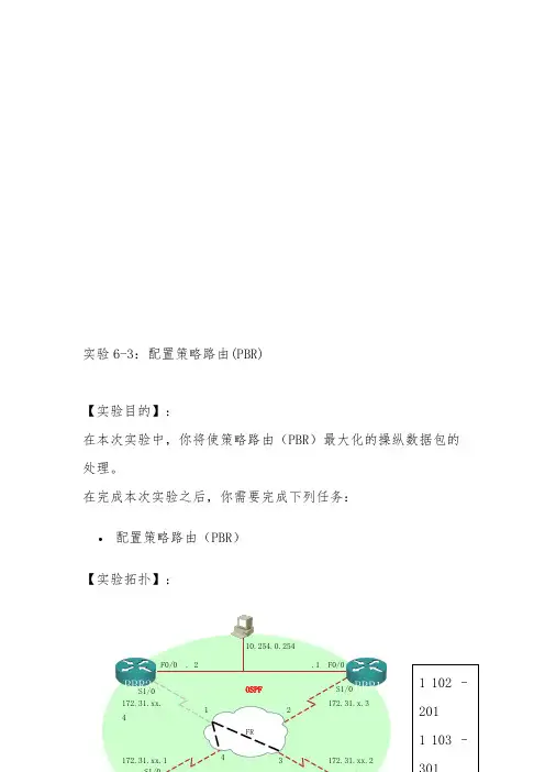
在完成本次实验之后,你需要完成下列任务:• 配置策略路由(PBR )【实验拓扑】:BBR2 BBR1 F0/0 . 2 .1 F0/0 10.254.0.254OSPFS1/0 S1/0 172.31.x.3 172.31.xx.1 102 –注意:图中x为所在机架编号,y为路由器编号。
【实验关心】:假如出现任何问题,能够向在值的辅导老师提出并请求提供关心。
【命令列表】:【任务一】:配置PBR配置PRB实验的目的是为了展示能够在配置任意路径中的作用,而不是路由器正常的路由选择过程。
那个实验的目的是假设你想操纵源地址为内部路由器(PxR3和PxR4)环回接口的数据包。
通常,数据包从PxR3的环回接口,走出你的实验机架,首先到达PxR1,然后是骨干路由器。
类似,数据从PxR3的环回接口,走回你的实验机架,首先到达PxR2然后是骨干路由器。
在那个实验中,你需要强制源地址为PxR3的环回接口的数据包先通过PxR1然后到达PxR2,最后达到骨干路由器。
源地址为PxR4的环回接口的数据包先通过PxR2,然后到达PxR1,最后达到骨干路由器。
实验过程:第一步:在OSPF路由配置模式下删除重分布列表。
因此BBR2将可不能拥有你的环回接口路由。
第二步:在两个边界路由器上,创建一个ACL 2去匹配直接连接的内路路由器的环回接口。
P1R1#show access-listsStandard IP access list 110 permit 10.200.200.0, wildcard bits 0.0.0.255 (10 matches)Standard IP access list 210 permit 10.1.0.0, wildcard bits 0.0.255.255 (88 matches)P1R1#第三步:在边界路由器上,PxR1和PxR2上,创建一个Route-map。
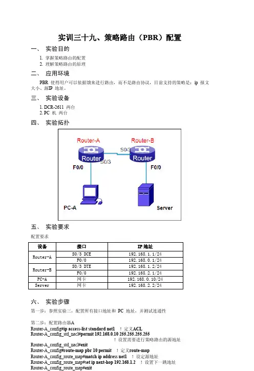
实训三十九、策略路由(PBR)配置一、实验目的1. 掌握策略路由的配置2. 理解策略路由的原理二、应用环境PBR 使得用户可以依据饿来进行路由,而不是路由协议,目前支持的策略是:ip 报文大小、源IP 地址。
三、实验设备1. DCR-2611 两台2. PC 机两台四、实验拓扑五、实验要求配置要求六、实验步骤第一步:参照实验三,配置所有接口地址和PC 地址,并测试连通性第二步:配置路由器ARouter-A_config#ip access-list standard net1 !定义ACLRouter-A_config_std_nacl#permit 192.168.0.10 255.255.255.255!设置需要进行策略路由的源地址Router-A_config_std_nacl#exitRouter-A_config#route-map pbr 10 permit !定义route-mapRouter-A_config_route_map#match ip address net1 !设定源地址Router-A_config_route_map#set ip next-hop 192.168.1.2 !设置下一跳地址Router-A_config_route_map#exitRouter-A_config#int f0/0 !进入源地址的路由器接口Router-A_config_f0/0#ip policy route-map pbr !绑定route-map第三步:配置路由器B 的路由表Router-B#confRouter-B_config#ip route 192.168.0.0 255.255.255.0 192.168.1.1第四步:查看路由器A、B 的路由表Router-A#show ip routeCodes: C - connected, S - static, R - RIP, B - BGP, BC - BGP connectedD - BEIGRP, DEX - external BEIGRP, O - OSPF, OIA - OSPF inter areaON1 - OSPF NSSA external type 1, ON2 - OSPF NSSA external type 2OE1 - OSPF external type 1, OE2 - OSPF external type 2DHCP - DHCP type, L1 - IS-IS level-1, L2 - IS-IS level-2VRF ID: 0C 192.168.0.0/24 is directly connected, FastEthernet0/0C 192.168.1.0/24 is directly connected, Serial0/3!注意到没有192.168.2.0 的路由Router-B#show ip routeCodes: C - connected, S - static, R - RIP, B - BGP, BC - BGP connectedD - BEIGRP, DEX - external BEIGRP, O - OSPF, OIA - OSPF inter areaON1 - OSPF NSSA external type 1, ON2 - OSPF NSSA external type 2OE1 - OSPF external type 1, OE2 - OSPF external type 2DHCP - DHCP type, L1 - IS-IS level-1, L2 - IS-IS level-2VRF ID: 0S 192.168.0.0/24 [1,0] via 192.168.1.1(on Serial0/3) !返回的数据包的路由C 192.168.1.0/24 is directly connected, Serial0/3C 192.168.2.0/24 is directly connected, FastEthernet0/0第五步:测试第六步:查看配置Router-A#show ip policyInterface Route-mapFastEthernet0/0 pbrRouter-A#show route-mapRoute-map pbr, permit, sequence 10Match clauses:match ip address net1Set clauses:set ip next-hop 192.168.1.2Exit policy:Policy routing matches: 142 packets, 10366 bytes七、注意事项和排错1. 注意是源地址匹配的路由2. 绑定在源数据包的接口上八、共同思考1. 策略路由与路由协议进行的路由有什么区别?2. 为什么在路由器B 上要配置静态路由?3. 如果源地址是192.168.0.2/24,那么策略还有效吗?九、课后练习请将源地址改为192.168.0.2/24 重复以上实验。
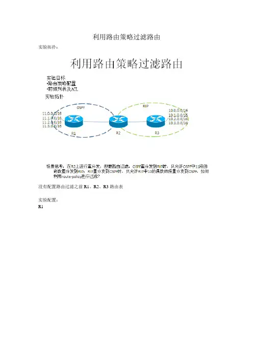
利用路由策略过滤路由实验拓扑:
没有配置路由过滤之前R1、R2、R3路由表
实验配置:
R1
R2
R2上配置acl 2000中第一条acl的意思是拒绝11.0.0.0/16网段中的偶数网段,第二条的意思是允许11.0.0.0/16网段中的所有网段。
Acl 2001中第一条命令的意思是拒绝10.0.0.0/16网段中的奇数数网段,第二条的意思是允许10.0.0.0/16网段中的所有网段。
R3
实验结果验证:
查看R1上的路由表:
查看R2上的路由表:
实验结果完全符合实验实验要求,R1上只有10.0.0.0/16的偶数网段,R3上也只有11.0.0.0/16的奇数网段。
实验思考:
根据R2实验配置得出,当acl语句是deny,route-policy语句是permit时,route-policy依然执行的deny。
那么当acl语句是permit,route-policy语句是deny是,route-policy执行的是deny还是permit?
修改R2上实验配置:
查看R3上路由表变化
总结:在使用路由策略引用acl时,当路由策略和acl定义的动作不一样时,动作定义为deny。


配置策略路由实验汇报人:日期:•实验背景与目标•实验环境与准备•实验步骤与操作•实验数据与结果分析•实验总结与展望•参考文献与致谢01实验背景与目标背景介绍实验目标02实验环境与准备路由器交换机计算机030201实验设备实验拓扑1. 核心层:由一台Cisco 2811路由器组成,连接各个实验软件与工具03实验步骤与操作设备启动与登录基础配置设备管理配置路由器基本功能确定目标网络在路由器上指定目标网络,并设置下一跳地址,完成静态路由的配置。
配置静态路由验证配置配置策略路由规则在路由器上创建策略路由规则,并指定对应的接口或下一跳地址。
确定策略路由规则根据实际需求,确定数据包转发的规则,例如根据源IP地址、目标IP地址等因素进行匹配。
验证配置通过数据流测试,验证策略路由规则是否按照预期进行数据包转发。
04实验数据与结果分析分析不同路由策略下的数据,比较静态路由和动态路由的优劣。
分析不同负载情况下的数据,比较负载均衡和负载分担的差异。
分析不同网络流量情况下的数据,比较策略路由在不同流量情况下的表现。
通过图表展示不同网络流量情况下策略路由的吞吐量、延迟等指标。
通过图表展示不同路由策略下策略路由的可用性、稳定性等指标。
通过图表展示不同负载情况下负载均衡和负载分担的效果。
结果展示05实验总结与展望实验总结成功实现验证了理论达到预期效果规则冲突性能影响配置复杂问题与改进03应用扩展01深入研究02优化配置未来展望06参考文献与致谢[1] 张三, 李四. 策略路由实验指导书[M]. 北京: 人民邮电出版社,2020.[2] 王五, 赵六. 策略路由技术研究报告[R]. 上海: 上海交通大学,2021.[3] 刘七, 马八. 基于策略路由的流量工程优化论文[J]. 计算机学报, 2022, 45(3): 401-410.参考文献致谢感谢实验室的领导和工作人员在实验过程中的关心和支持。
THANK YOU。
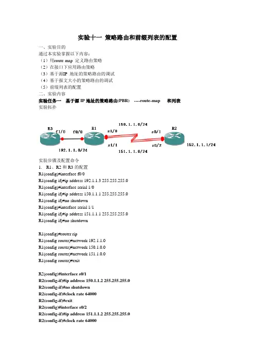
实验十一策略路由和前缀列表的配置一、实验目的通过本实验掌握以下内容:(1)用route-map 定义路由策略(2)在接口下应用路由策略(3)基于源IP 地址的策略路由的调试(4)基于报文大小的策略路由的调试(5)前缀列表的配置二、实验内容实验任务一基于源IP地址的策略路由(PBR) ----route-map 和列表实验拓扑实验步骤及配置命令1.R1、R2和R3的配置R1(config)#interface f0/0R1(config-if)#ip address 192.1.1.3 255.255.255.0R1(config)#interface serial 1/0R1(config-if)#ip address 150.1.1.1 255.255.255.0R1(config-if)#no shutdownR1(config)#interface serial 1/1R1(config-if)#ip address 151.1.1.1 255.255.255.0R1(config-if)#no shutdownR1(config)#router ripR1(config-router)#network 192.1.1.0R1(config-router)#network 150.1.0.0R1(config-router)#network 151.1.0.0R1(config-router)#exitR2(config)#interface s0/1R2(config-if)#ip address 150.1.1.2 255.255.255.0R2(config-if)#no shutdownR2(config-if)#clock rate 64000R2(config-if)#exitR2(config)#interface s0/2R2(config-if)#ip address 151.1.1.2 255.255.255.0R2(config-if)#clock rate 64000R2(config-if)#no shutdownR2(config-if)#exitR2(config)#interface loopback 0R2(config-if)#ip address 152.1.1.1 255.255.255.0R2(config-if)#exitR2(config)#router ripR2(config-router)#network 150.1.0.0R2(config-router)#network 151.1.0.0R2(config-router)#network 152.1.0.0R2(config)#do wrR3(config)#interface f1/0R3(config-if)#ip address 192.1.1.1 255.255.255.0R3(config-if)#ip address 192.1.1.2 255.255.255.0 secondary2. R1(config)#access-list 1 permit 192.1.1.1 0.0.0.0R1(config)#access-list 2 permit 192.1.1.2 0.0.0.0定义两台服务器的IPR1(config)#route-map lab1 permit 10R1(config-route-map)#match ip address 1R1(config-route-map)#set ip next-hop 150.1.1.2R1(config-route-map)#exitRoute Map表lab1的第一条语句,服务器192.1.1.1的数据经过下一跳地址是150.1.1.2即s0/1发送,条件语句嵌套ACL1R1(config)#route-map lab1 permit 20R1(config-route-map)#match ip address 2R1(config-route-map)#set ip next-hop 151.1.1.2R1(config-route-map)#exitRoute Map表lab1的第二条语句,服务器192.1.1.2的数据经过下一跳地址是151.1.1.2即s0/2发送,条件语句嵌套ACL2R1(config)#interface f 0/0R1(config-if)#ip policy route-map lab1在f 0/0接口上应用名字是lab1的Route Map表R1(config)#ip local policy route-map lab1要求路由器本身产生的数据包也接受策略路由的管理2.测试扩展的traceroute 命令R3#traceroute ipTarget IP address: 152.1.1.1Source address: 192.1.1.1Numeric display [n]:Timeout in seconds [3]:Probe count [3]:Minimum Time to Live [1]:Maximum Time to Live [30]:Port Number [33434]:Loose, Strict, Record, Timestamp, Verbose[none]: Type escape sequence to abort.Tracing the route to 152.1.1.11 150.1.1.2 56 msec * 72 msecR3#traceroute ipTarget IP address: 152.1.1.1Source address: 192.1.1.2Numeric display [n]:Timeout in seconds [3]:Probe count [3]:Minimum Time to Live [1]:Maximum Time to Live [30]:Port Number [33434]:Loose, Strict, Record, Timestamp, Verbose[none]: Type escape sequence to abort.Tracing the route to 152.1.1.11 151.1.1.2 56 msec * 52 msec另一种测试源IP地址的策略路由使用debug ip policy命令来监视策略路由R1#debug ip policyPolicy routing debugging is onR3#pingProtocol [ip]:Target IP address: 152.1.1.1Repeat count [5]:Datagram size [100]:Timeout in seconds [2]:Extended commands [n]: ySource address or interface: 192.1.1.1Type of service [0]:Set DF bit in IP header? [no]:Validate reply data? [no]:Data pattern [0xABCD]:Loose, Strict, Record, Timestamp, Verbose[none]:Sweep range of sizes [n]:Type escape sequence to abort.Sending 5, 100-byte ICMP Echos to 152.1.1.1, timeout is 2 seconds: Packet sent with a source address of 192.1.1.1!!!!!Success rate is 100 percent (5/5), round-trip min/avg/max = 4/51/128 ms 这样路由器R1会输出debug ip policy监视所得的结果,截图该命令显示定义的所有路由策略及路由策略匹配的情况。


策略路由实验报告策略路由是一种基于策略的路由选择方式,它通过制定具体的策略来根据不同的条件选择最优的路由。
策略路由在网络管理和优化中扮演着重要的角色,能够提高网络的灵活性和可管理性。
策略路由实验是为了验证策略路由的有效性和性能,通过构建实验环境,设计一系列的实验任务并进行实测,从而得出关于策略路由的实际应用效果和其他相关指标的实验结果。
本次策略路由实验针对网络拓扑和流量分布设计了一套策略路由方案,主要包括以下几个实验任务:1. 实验环境的构建:选择适当的网络拓扑和流量模型,构建实验所需的拓扑结构,并设置合理的流量分布。
2. 策略路由的设计:根据实验的目标,制定一套合适的策略路由方案,包括路由策略的定义和配置、优先级的设置等。
3. 策略路由的实验性能评估:通过实验数据的采集和分析,评估策略路由的性能表现,包括转发延迟、带宽利用率、丢包率等指标。
4. 策略路由与其他路由方案的对比:将策略路由与其他常见的路由方案进行对比,比如静态路由、动态路由等,评估其在实验环境下的性能差距。
5. 实验结果的分析和总结:根据前面的实验数据和对比结果,分析策略路由的优越性、适用性和局限性,并对实验得出的结论进行总结和归纳。
在整个实验过程中,需要进行详细的实验设计和规划,包括实验的目标、实验环境的构建、实验参数的设置等。
同时需要注意实验过程的可重复性和可验证性,确保实验结果的准确性。
在实验过程中,还需要合理运用统计学方法和数据分析技巧,对实验数据进行处理和分析。
最后,根据实验结果和结论,可以进一步展开相关的研究工作,比如进一步改进策略路由方案、探索优化策略路由的方法等。
实验报告应当包含实验设计和原理介绍、实验结果分析和总结等内容,结合实际情况进行详细回答,完整展示实验过程和实验结果。
【路由策略】的配置实验总结与心得一、实验目的1.1 了解路由策略的基本概念和作用;1.2 掌握路由策略的配置方法和步骤;1.3 探索路由策略在网络管理中的应用。
二、实验环境2.1 使用华为、思科或者Juniper等品牌的路由器搭建实验环境;2.2 准备多台主机模拟复杂网络环境。
三、实验步骤3.1 搭建实验环境;3.2 配置基本的路由策略;3.3 模拟不同网络场景,测试路由策略的效果;3.4 总结实验数据,分析路由策略在不同情况下的表现。
四、实验总结4.1 路由策略的优点和局限性;4.2 路由策略配置中的注意事项;4.3 路由策略在网络管理中的重要性;4.4 对未来路由策略发展的展望。
五、心得体会5.1 通过本次实验,我深刻理解了路由策略的概念和作用,掌握了路由策略的配置方法和步骤;5.2 在实验中遇到了一些问题,但通过不断的调整和优化,最终取得了满意的实验效果;5.3 路由策略在网络管理中起着至关重要的作用,可以根据实际需求灵活调整,提高网络的安全性和稳定性;5.4 未来,随着网络规模的不断扩大和网络安全形势的复杂化,路由策略的发展方向将更加多样化和智能化。
六、结语6.1 本次实验让我受益匪浅,对于路由策略有了更深入的了解和认识;6.2 我将继续深入学习和实践,不断提升自己在网络管理领域的能力和水平;6.3 我相信,在不久的将来,我一定能够在实际工作中充分发挥所学所用,为公司的网络安全和稳定运行贡献自己的力量。
五、心得体会5.1 本次实验让我深刻理解了路由策略的重要性和复杂性。
在配置路由策略的过程中,需要考虑网络拓扑、数据流向、安全需求等多个因素,这需要综合考虑和灵活调整,在实际应用中能够体现出其价值和作用。
5.2 在实验中,我遇到了一些问题,比如在配置路由策略时需要考虑到网络中的具体情况,包括网络流量、数据包的传输路径、安全需求等。
在实际操作中,需要仔细思考和分析,确保所配置的路由策略能够满足实际需求,提高网络的安全性和稳定性。
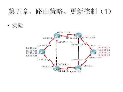
路由策略综合实验一、路由策略综合实验拓扑图,如图1.1所示:图1.1 路由策略综合实验拓扑图二、实验要求:1.R1上重分布EIGRP100的路由进入到EIGRP125和OSPF域,发进EIGRP125要求汇总(R1 loopback 宣告进OSPF域).2.R5上一定要通过汇总路由到达EIGRP100,到达EIGRP域要优选R1这条路3.R2上单点双向重分布(保证5可以到ospf域,ospf可以到达EIGRP 125),要求发进EIGRP的时候考虑eigrp 100的明细路由(需求 2)发到OSPF 的时候要考虑那条汇总路由4.Area23要求优化LSA(考虑R2做重分布),保证R3具有可达性(R2发默认路由)5.R3重分布OSPF到RIP,保证R4可以通过OSPF到达全网(考虑R2给R3的默认路由)6.R5重分布EIGRP到RIP(思考如果R3首先重分布路由给R4,R5如何重分布EIGRP给R4)7.保证R4不存在次优路径,可以通过OSPF和EIGRP同时到达的区域,优选EIGRP三、各路由器初始配置://R1的初始配置:R1(config)#interface Loopback0R1(config-if)# ip address 172.16.0.1 255.255.255.0R1(config-if)#interface Loopback1R1(config-if)# ip address 172.16.1.1 255.255.255.0R1(config-if)#interface Loopback2R1(config-if)# ip address 172.16.2.1 255.255.255.0R1(config-if)#interface Loopback3R1(config-if)# ip address 172.16.3.1 255.255.255.0 R1(config-if)#interface Loopback4R1(config-if)# ip address 10.0.0.1 255.255.255.0 R1(config-if)#interface Loopback5R1(config-if)# ip address 1.1.1.1 255.255.255.0R1(config-if)#interface Serial2/1R1(config-if)# ip address 12.0.0.1 255.255.255.0 R1(config-if)#no shutdownR1(config-if)#interface Serial2/2R1(config-if)# ip address 15.0.0.1 255.255.255.0 R1(config-if)#no shutdown//R2的基础配置R2(config)#interface Loopback0R2(config-if)# ip address 2.2.2.2 255.255.255.0R2(config-if)#interface FastEthernet0/0R2(config-if)# ip address 25.0.0.2 255.255.255.0 R2(config-if)#no shutdownR2(config-if)#interface Serial2/1R2(config-if)# ip address 12.0.0.2 255.255.255.0 R2(config-if)# no shutdownR2(config-if)#interface Serial2/2R2(config-if)# ip address 23.0.0.2 255.255.255.0 R2(config-if)# no shutdown//R3的具体配置R3(config)#interface Loopback0R3(config-if)# ip address 3.3.3.3 255.255.255.0R3(config-if)#interface Serial2/1R3(config-if)# ip address 23.0.0.3 255.255.255.0 R3(config-if)#no shutdownR3(config-if)#interface Serial2/2R3(config-if)# ip address 34.0.0.3 255.255.255.0 R3(config-if)#no shutdown//R4的具体配置R4(config)#interface Loopback0R4(config-if)# ip address 4.4.4.4 255.255.255.0R4(config-if)#interface Serial2/1R4(config-if)# ip address 34.0.0.4 255.255.255.0 R4(config-if)# no shutdownR4(config-if)#interface Serial2/2R4(config-if)# ip address 45.0.0.4 255.255.255.0 R4(config-if)# no shutdown//R5的具体配置R5(config)#interface Loopback0R5(config-if)# ip address 5.5.5.5 255.255.255.0R5(config-if)#interface FastEthernet0/0R5(config-if)# ip address 25.0.0.5 255.255.255.0R5(config-if)#no shutdownR5(config-if)#interface Serial2/1R5(config-if)# ip address 15.0.0.5 255.255.255.0R5(config-if)# no shutdownR5(config-if)#interface Serial2/2R5(config-if)# ip address 45.0.0.5 255.255.255.0R5(config-if)# no shutdown四、实验配置:1.R1上的具体配置://开启eigrp100并激活相应网络接口R1(config-if)#router eigrp 100R1(config-router)# network 10.0.0.1 0.0.0.0R1(config-router)# network 172.16.0.0 0.0.3.255R1(config-router)# no auto-summary //关闭自动汇总//开启eigrp125,激活相应网络接口,充分发路由R1(config-router)#router eigrp 125R1(config-router)# redistribute eigrp 100//将eigrp100充分发到eigrp125R1(config-router)# network 15.0.0.1 0.0.0.0R1(config-router)# distribute-list 1 in Serial2/2//开启分布列表控制流量拒绝2.2.2.0/24和172.16.0.0/22的流量从S2/2接口进入eigrp域内R1(config-router)# no auto-summaryR1(config-router)#R1(config-router)#router ospf 1R1(config-router)# router-id 1.1.1.1R1(config-router)# redistribute eigrp 100 subnets//将eigrp100重分发进ospf1R1(config-router)# network 1.1.1.1 0.0.0.0 area 0R1(config-router)# network 12.0.0.1 0.0.0.0 area 0R1(config)#access-list 1 deny 2.2.2.0 0.0.0.255 //抓取2.2.2.0/24的流量,控制次优R1(config)#access-list 1 deny 172.16.0.0 0.0.3.255 //抓取172.16.0.0/24的流量R1(config)#access-list 1 premit any2.R2上的具体配置://在R2上开启eigrp125,并将ospf1重分发进eigrpR2(config-if)#router eigrp 125R2(config-router)#$ 1 1500 match internal nssa-external //只允许ospf内部路由和nssa外部路由重分发进入eigrp125 R2(config-router)# network 25.0.0.2 0.0.0.0R2(config-router)# distribute-list 1 in FastEthernet0/0 //控制次优路径172.16.0.0/22R2(config-router)# no auto-summaryR2(config-router)#R2(config-router)#router ospf 1R2(config-router)# router-id 2.2.2.2R2(config-router)# area 23 nssa default-information-originate //将area23设置成为nssa域并在area23里面传播默认路由R2(config-router)# redistribute eigrp 125 subnets //将eigrp125重分布进入ospf1 R2(config-router)# network 2.2.2.2 0.0.0.0 area 0R2(config-router)# network 12.0.0.2 0.0.0.0 area 0R2(config-router)# network 23.0.0.2 0.0.0.0 area 23R2(config)#access-list 1 deny 172.16.0.0 0.0.3.255 //抓取172.16.0.0/22的流量R2(config)#access-list 1 permit any3.R3上的具体配置R3(config-if)#router ospf 1R3(config-router)# router-id 3.3.3.3R3(config-router)# area 23 nssa //在R3上将area23也设置成为nssa区域R3(config-router)# network 23.0.0.3 0.0.0.0 area 23R3(config-router)#R3(config-router)#router ripR3(config-router)# version 2R3(config-router)# redistribute ospf 1 metric 5 route-map deny0//重分布ospf进入rip 并用route-map deny0控制流量,避免默认路由传入,防止环路R3(config-router)# network 3.0.0.0R3(config-router)# network 34.0.0.0R3(config-router)# no auto-summaryR3(config-router)#R3(config)#access-list 1 deny 0.0.0.0//抓取默认路由的流量R3(config)#access-list 1 permit anyR3(config)#R3(config)#route-map deny0 deny 10 //写拒绝路由映射,控制默认路由R3(config-route-map)# match ip address 14.R4上的具体配置//在R4上开启rip v2,宣告相应网络R4(config-if)#router ripR4(config-router)# version 2R4(config-router)# network 4.0.0.0R4(config-router)# network 34.0.0.0R4(config-router)# network 45.0.0.0R4(config-router)# no auto-summary5.R5上的具体配置//在R5上开启eigrp125,宣告相应网络,并将rip重分布进入其中R5(config-if)#router eigrp 125R5(config-router)# redistribute rip metric 10000 100 255 1 1500//重分布rip进eigrp R5(config-router)# network 5.0.0.0R5(config-router)# network 15.0.0.5 0.0.0.0R5(config-router)# network 25.0.0.5 0.0.0.0R5(config-router)# no auto-summary//开启rip进程,宣告相应网络,并将eigrp125重分布进入ripR5(config-router)#router ripR5(config-router)# version 2R5(config-router)# redistribute eigrp 125 metric 3 //重分布eigrp125进入rip,并将度量设置为3,选定eigrp为最优路径R5(config-router)# network 45.0.0.0R5(config-router)# no auto-summary经过以上配置以后,已经将全网互通,而且已经将次优路径剔除干净。
CCNP实验总结(路由策略部分)一.路由重分布1.最佳路由重分布解决方案R1下配置:inter loo 0ip add 1.1.1.1 255.255.255.0inter s0/0ip add 192.168.0.1 255.255.255.0no shurouter ripver 2no aunet 1.1.1.0net 192.168.0.0R2下配置:inter s0/0ip add 192.168.0.2 255.255.255.0no shuinter s0/1ip add 192.168.1.1 255.255.255.0no shuip route 0.0.0.0 0.0.0.0 192.168.1.2router ripver 2no aunet 192.168.0.0redistribute static metric 1router ospf 100net 192.168.1.1 0.0.0.0 a 0redistribute rip subnetsR3下配置:inter s0/1ip add 192.168.1.2 255.255.255.0no shuinter loo 0ip add 3.3.3.3 255.255.255.0ip ospf net point-to-prouter ospf 100net 192.168.1.2 0.0.0.0 a 0net 3.3.3.0 0.0.0.255 a 02.RIP下分布OSPFredistribute ospf 100 metric 1-153.EIGRP下分布OSPFredistribute ospf 100 metric 1544 200 255 1 15004.OSPF下分布RIP/EIGRPreidistribute rip/eigrp 100 subnets5.EIGRP下分布IS-ISredistribute isis level-1/-1-2/-2 metric 1544 200 255 1 15006.IS-IS下分布EIGRPredistribute eigrp 100 level-1/-1-2/-2二.被动接口RIP下只接受更新不发送更新,OSPF/IS-IS/EIGRP下不向外发送hello包,不建立邻居关系router eigrp 100passive-interface s0/0passive-interface default (全部接口)三.控制路由更新1.出向router eigrp 100distribute-list acl out interface/process路由重分布只能用出向列表(能加路由进程)2.入向router eigrp 100distribute-list acl in interface3.prefix-listip prefix-list 1 permit 1.1.1.0/24 ge 25 le 30所有B类地址的子网路由,长度不超过24ip prefix-list 1 permit 128.0.0.0/2 ge 17 le 244.加入网关distribute-list gateway prefix-list…gateway:距离矢量,到达目的网段的下一跳链路状态,通告这条路由的路由器5.基于时间的ACLtime-range aaaabsolute (绝对)/periodicperiodic Monday-Sunday 9:00 to 12:00dailyweekdays (Monday to Friday)weekend (Saturday to Sunday)access-list 100 permit tcp any any eq 80 time-range aaa6.OSPF中的分布列表不允许用出向(同一区域内LSDB要同步),入向数据库中有条目,不加路由表7.双向多点重分布时的路由回馈问题R2先于R3配置好R3会认为1.0-3.0网段是从R4发来的(管理距离问题)解决办法:1.修改R1-R3 RIP的管理距离2.去掉R38.策略路由access-list 1 permit 1.1.1.0 0.0.0.255route-map name permit num(从小往大写)match ip address address/acl num/prefix-list numset (e.g. metric 100)router ospf 100redistribute rip route-map name subnets9.IS-IS的被重分布问题需要重分布直连链路:redistribute connected10.管理距离的修改router eigrp 100distance eigrp num(内部) num(外部)distance 1 1.1.1.0 255.255.255.0/aclrouter ospf 100distance 1 1.1.1.0/acl gateway acl num11.现网不用debug,流量过大,慎用no语句12.DHCP交换信息用broadcast,每到周期的一半,再申请一次,如此循环。
一、实验项目名称路由器上配置DHCP、策略路由二、实验目的配置DHCP及完成策略路由。
三、实验设备Switch2960-24TT 1台,PC 3台,Router-PT 4台,直通线3条,交叉网线2条,串行线3条。
四、实验步骤路由器上配置DHCP:新建Packet Tracer拓扑图PC0自动获取PC1自动获取R1配置命令如下:Enconfig thost R1int f0/0ip address 192.168.10.1 255.255.255.0no shutint s1/1ip address 12.1.1.1 255.255.255.0clock rate 64000no shutexitip route 192.168.11.0 255.255.255.0 12.1.1.2R2的配置enconfig tint f0/0ip address 192.168.11.1 255.255.255.0no shutint s2/0ip address 12.1.1.2 255.255.255.0no shutexitip route 192.168.10.0 255.255.255.0 12.1.1.1R1配置ip dhcp pool zhulou //配置主楼DHCP地址池network 192.168.10.0 255.255.255.0 //动态分配192.168.10.0/24这个网段内的IP地址dns-server 218.2.135.1 //为主楼计算机配置DNS服务器default-router 192.168.10.1 //为主楼的客户机配置网关ip dhcp pool fulou //配置辅楼DHCP地址池network 192.168.11.0 255.255.255.0 //动态分配192.168.11.0/24这个网段内的IP 地址dns-server 218.2.135.1 //为辅楼计算机配置DNS服务器default-router 192.168.11.1 //为辅楼的客户机配置网关exitip dhcp excluded-address 192.168.10.1 //排除主楼客户机的网关ip dhcp excluded-address 192.168.11.1 //排除辅楼客户机的网关no ip dhcp conflict logging //不配置数据库代理R2配置(配置DHCP中继)int f0/0ip helper-address 12.1.1.1 //配置辅助寻址,指向DHCP服务器的地址,即路由器R1的IP地址最后PC0、PC1查看IP地址,如果有,则成功。
实验十二:IP策略路由一、理论基础通过设置IP策略路由,可以将不同的数据源按照管理员的要求从指定的端口流出,通过这种对数据流的策略设置,使得网络更加的有效和安全。
二、实验案例IP策略路由的配置1、实验拓扑结构图:2、配置说明:RouterB的S0<---> RouterA的S0Switch的E0/1<--->RouterA的E0RouterA的E1<---> RouterC的E0Switch的E0/2<--->PC1Switch的E0/3<--->PC2PC1的地址:40.1.1.2/25 网关:40.1.1.1PC2的地址:40.1.1.130/25 网关:40.1.1.129路由器B的S0地址:192.168.1.2/24路由器A的S0地址:192.168.1.1/24路由器A的E1地址:192.168.2.1/24路由器A的E0接口创建两个子接口地址: E0.1:40.1.1.1 255.255.255.128E0.2:40.1.1.129 255.255.255.128交换机的配置:端口E0/1设置为Trunk;E0/2加到VLAN2,端口E0/3加到VLAN3。
3、具体配置:[Router]sys routerB[routerB]int s0[RouterB-Serial0]ip address 192.168.1.2 255.255.255.0[RouterB-Serial0]%10:41:22: Line protocol ip on the interface Serial0 is UP 路由器B启动RIP协议:[routerB]ripwaiting...RIP is running[routerB-rip]network all[routerB-rip]dis curNow create configuration...Current configurationversion 1.74sysname routerBfirewall enableaaa-enableaaa accounting-scheme optionalinterface Aux0async mode flowlink-protocol pppinterface Ethernet0interface Serial0link-protocol pppip address 192.168.1.2 255.255.255.0interface Serial1link-protocol pppinterface Serial2link-protocol pppquitripnetwork allquit保存配置:[routerB]saveNow writing the running config to flash memory.Please wait for a while......write the running config to flash memory successfullyreturn给路由器A的S0接口加地址:192.168.1.1/24[Router]sys routerA[routerA]int s0[routerA-Serial0]ip address 192.168.1.1 255.255.255.0 [routerA-Serial0]%10:56:26: Line protocol ip on the interface Serial0 is UP 给路由器A的E1接口加地址:192.168.2.1/24[routerA]int e1[routerA-Ethernet1]ip address 192.168.2.1 255.255.255.0 [routerA-Ethernet1]%11:00:26: Line protocol ip on the interface Ethernet1 is UP 给路由器A的E0接口创建两个子接口并加地址:[routerA]int e0.1[routerA-Ethernet0.1]vlan-type dot1q vid 2[routerA-Ethernet0.1]ip address 40.1.1.1 255.255.255.128 [routerA-Ethernet0.1]%11:04:26: Line protocol ip on the interface Ethernet0.1 is UP [routerA-Ethernet0.1]int e0.2[routerA-Ethernet0.2]vlan-type dot1q vid 3[routerA-Ethernet0.2]ip address 40.1.1.129 255.255.255.128 [routerA-Ethernet0.2]%11:05:20: Line protocol ip on the interface Ethernet0.2 is UP [routerA]rip[routerA-rip]network all[routerA]dis curNow create configuration...Current configurationversion 1.74sysname routerAfirewall enableaaa-enableaaa accounting-scheme optionalinterface Aux0async mode flowlink-protocol pppinterface Ethernet0interface Ethernet0.1vlan-type dot1q vid 2ip address 40.1.1.1 255.255.255.128interface Ethernet0.2vlan-type dot1q vid 3ip address 40.1.1.129 255.255.255.128interface Ethernet1ip address 192.168.2.1 255.255.255.0interface Serial0clock DTECLK1link-protocol pppip address 192.168.1.1 255.255.255.0interface Serial1link-protocol pppinterface Serial2link-protocol pppinterface Serial3link-protocol pppquitripnetwork allquitreturn交换机的配置:接口1为干道:端口2加到VLAN2;端口3加到VLAN3[Quidway]vlan 2[Quidway-vlan2]vlan 3[Quidway-vlan3]port e0/3[Quidway-vlan3]vlan 2[Quidway-vlan2]port e0/2[Quidway]int e0/1[Quidway-Ethernet0/1]port link-type trunk[Quidway-Ethernet0/1]port trunk permit vlan allPlease wait........................................... Done. [Quidway]dis cursysname Quidwayradius scheme systemserver-type huaweiprimary authentication 127.0.0.1 1645primary accounting 127.0.0.1 1646user-name-format without-domaindomain systemradius-scheme systemaccess-limit disablestate activevlan-assignment-mode integeridle-cut disableself-service-url disablemessenger time disabledomain default enable systemlocal-server nas-ip 127.0.0.1 key huaweiqueue-scheduler wrr 1 2 4 8vlan 1vlan 2vlan 3interface Vlan-interface3interface Aux0/0interface Ethernet0/1port link-type trunkport trunk permit vlan allinterface Ethernet0/2port access vlan 2interface Ethernet0/3port access vlan 3interface Ethernet0/4interface Ethernet0/5interface Ethernet0/6interface Ethernet0/7interface Ethernet0/8interface NULL0user-interface aux 0user-interface vty 0 4return[Quidway]quit<Quidway>saveThis will save the configuration in the flash memory.The switch configurations will be written to flash.Are you sure?[Y/N]yNow saving current configuration to flash memory.Please wait for a while...Current configuration saved to flash memory successfully.[routerA]acl 2008[routerA-acl-2008]rule normal permit source 40.1.1.0 0.0.0.127 Rule has been added to normal packet-filtering rules[routerA-acl-2008]rule normal deny source anyRule has been added to normal packet-filtering rules[routerA]acl 2009[routerA-acl-2009]rule normal permit source 40.1.1.128 0.0.0.127 Rule has been added to normal packet-filtering rules[routerA-acl-2009]rule normal deny source anyRule has been added to normal packet-filtering rules[RouterA] route-policy aaa permit 10[RouterA-route-policy] if-match ip address 2008[RouterA-route-policy] apply interface S0[RouterA] route-policy aaa permit 20[RouterA-route-policy] if-match ip address 2009[RouterA-route-policy] apply interface e1[RouterA-ethernet0] ip policy route-policy aaa三、实验总结在RouterA上做策略路由,从PC1来的40.1.1.0/25的报文被送往S0口,从PC2来的40.1.1.128/25的报文被送往E1。