2010cad工作界面
- 格式:doc
- 大小:980.00 KB
- 文档页数:12


CAD 2010工作界面CAD 2010简体中文版的工作界面如图1-10所示,主要包括有:标题栏、下拉菜单、绘图区、工具栏、命令栏、状态栏、属性栏等部分。
和其它应用程序一样,用户可以根据需要安排工作界面。
图1-10 中望CAD 2010中文版的界面标题栏:显示软件名称和当前图形文件名。
与Windows标准窗口一致,可以利用右上角的按钮将窗口最小化、最大化或关闭。
下拉菜单:单击界面上方的菜单,会弹出该菜单对应的下拉菜单,在下拉菜单中几乎包含了中望CAD所具有的所有的命令及功能选项,单击需要执行操作的相应选项,就会执行该项操作工具栏:工具栏按类别包含了不同功能的图标按钮,用户只需单击某个按钮即可执行相应的操作。
在工具栏上点击鼠标右键,可以调整工具栏显示的状态。
命令栏:命令栏位于工作界面的下方,当命令栏中显示“命令:”提示的时候,表明软件等待用户输入命令。
当软件处于命令执行过程中,命令栏中显示各种操作提示。
用户在绘图的整个过程中,要密切留意命令栏中的提示内容。
绘图区:绘图区位于屏幕中央的空白区域,所有的绘图操作都是在该区域中完成的。
在绘图区域的左下角显示了当前坐标系图标,向右方向为X轴正方向,向上为Y轴正方向。
绘图区没有边界,无论多大的图形都可置于其中。
鼠标移动到绘图区中,会变为十字光标,执行选择对象的时候,鼠标会变成一个方形的拾取框。
状态栏:状态栏位于界面的最下方,显示了当前十字光标在绘图区所处的绝对坐标位置。
同时还显示了常用的控制按钮,如捕捉、栅格、正交等,点击一次,按钮按下表示启用该功能,再点击则关闭。
CAD命令执行方式在中望CAD中,命令的执行方式有多种,例如可以通过按工具栏上的命令按钮或下拉菜单等。
当用户在绘图的时候,应根据视距情况选择最佳的命令执行方式,提高工作效率。
以键盘方式执行:通过键盘方式执行命令是最常用的一种绘图方法,当用户要使用某个工具进行绘图时,只需在命令行中输入该工具的命令形式,然后根据提示一步一步完成绘图即可。


第1章中望CAD 2010应用基础本章要点◼中望CAD 2010安装◼软件工作界面◼命令执行方式本章将介绍中望CAD 2010的最基本使用操作方法,包括软件的安装、启动、界面等内容。
若读者曾经使用过CAD软件,可跳过这章内容。
1.1中望CAD 2010的主要功能中望CAD是完全拥有自主知识产权、基于微软视窗操作系统的通用CAD绘图软件。
主要用于二维制图,兼有部分三维功能,被广泛应用于建筑、装饰、电子、机械、模具、汽车、造船等各领域,成为企业CAD正版化的最佳解决方案。
中望CAD的主要功能:1. 绘图功能用户可以通过输入命令及参数、单击工具按钮或执行菜单命令等方法来绘制各种图形,中望CAD会根据命令的具体情况给出相应的提示和可供选择的选项。
2. 编辑功能中望CAD提供各种方式让用户对单一或一组图形进行修改,可进行移动、复制、旋转、镜像等操作。
用户还可以改变图形的颜色、线宽等特性。
熟练掌握编辑命令的运用,可以成倍地提高绘图的速度。
3. 打印输出功能中望CAD具有打印及输出各种格式的图形文件的功能,可以调整打印或输出图形的比例、颜色等特征。
中望CAD支持大多数的绘图仪和打印机,并具有极好的打印效果。
4. 三维功能中望CAD专业版提供有三维绘图功能,可用多种方法按尺寸精确绘制三维实体,生成三维真实感图形,支持动态观察三维对象。
5. 高级扩展功能中望CAD作为一个绘图平台,提供了四种二次开发接口:LISP、VBA、SDS、ZRX,用户可以根据自己的需要定制特有的功能。
同时对于用户已有的二次开发程序,可以轻松移植到中望CAD上来。
1.2中望CAD 2010的软硬件要求在安装和运行ZWCAD的时候,软件和硬件必须达到以下要求:硬件与软件要求处理器Pentium III 800 MHz或更高内存512 MB(推荐)显示器1024 x 768 VGA 真彩色(最低要求)硬盘350 MBDVD-ROM 任意速度(仅用于安装)定点设备鼠标、轨迹球或其他设备操作系统Windows2000、Windows XP、Windows 2003、Windows Vista、Windows 7对于现阶段计算机的配置来说,以上的要求不高。


AutoCAD2010教程AutoCAD 2010的主要功能•二维绘图与编辑•创建表格•文字标注•尺寸标注•参数化绘图•三维绘图与编辑•视图显示控制AutoCAD 2010的主要功能•各种绘图实用工具•数据库管理•Internet功能•图形的输入、输出•图纸管理•开放的体系结构第1章基本概念与基本操作本章要点•安装、启动AutoCAD 2010 •AutoCAD 2010经典工作界面•AutoCAD命令及其执行方式•图形文件管理•确定点的位置•绘图基本设置与操作•AutoCAD 2010帮助功能1.1安装、启动AutoCAD20101.安装AutoCAD2010AutoCAD2010软件以光盘形式提供,光盘中有名为SETUP.EXE的安装文件。
执行SETUP.EXE文件,根据弹出的窗口选择、操作即可。
2.启动AutoCAD 2010安装AutoCAD2010后,系统会自动在Windows桌面上生成对应的快捷方式。
双击该快捷方式,即可启动AutoCAD 2010。
与启动其他应用程序一样,也可以通过Windows资源管理器、Windows任务栏按钮等启动AutoCAD2010。
菜单栏 光标 状态栏 命令窗口 坐标系图标模型/布局选项卡 绘图窗口 “样式”工具栏滚动条“绘图”工具栏菜单浏览器 “工作空间”工具栏“图层”工具栏 “特性”工具栏 “修改”工具栏“快速访问”工具栏“标准”工具栏 标题栏1. 标题栏标题栏与其他Windows应用程序类似,用于显示AutoCAD 2010的程序图标以及当前所操作图形文件的名称。
2. 菜单栏菜单栏是主菜单,可利用其执行AutoCAD的大部分命令。
单击菜单栏中的某一项,会弹出相应的下拉菜单。
右下图为“视图”下拉菜单。
下拉菜单中,右侧有小三角的菜单项,表示它还有子菜单。
右图显示出了“缩放”子菜单;右侧有三个小点的菜单项,表示单击该菜单项后要显示出一个对话框;右侧没有内容的菜单项,单击它后会执行对应的AutoCAD命令。

浩辰CAD2010标准版简介浩辰CAD2010是一款功能强大的计算机辅助设计(CAD)软件,专为建筑、土木工程和机械设计等行业开发。
它具有直观的用户界面、丰富的工具和功能,可以帮助用户简化设计流程、提高工作效率,并产生高质量的设计图纸和模型。
本文档将向您介绍浩辰CAD2010标准版的特点、系统要求、安装步骤和主要功能。
特点•直观的用户界面:浩辰CAD2010采用经典的Ribbon界面,使用户可以方便地找到需要的工具和功能。
•强大的绘图工具:浩辰CAD2010提供了各种绘图工具,包括直线、圆、矩形、多段线等,可以满足不同设计需求。
•高度可定制性:浩辰CAD2010允许用户自定义工具栏、菜单和快捷键,以适应个人的工作习惯。
•支持多种文件格式:浩辰CAD2010可以打开和保存多种文件格式,包括DWG、DXF、DGN等,方便与其他CAD软件进行文件交换。
•丰富的扩展性:浩辰CAD2010支持插件开发,用户可以根据自己的需求编写插件,扩展软件的功能。
系统要求•操作系统:Windows XP/Vista/7/8/10•处理器:Intel Core i3或更高版本•内存:4GB或更多•存储空间:至少1GB的可用空间•显卡:支持OpenGL 3.3或更高版本的显卡安装步骤以下是浩辰CAD2010标准版的安装步骤:1.下载浩辰CAD2010安装程序,双击运行。
2.在安装向导中选择安装语言,并点击“下一步”。
3.阅读软件许可协议,并接受后点击“下一步”。
4.选择安装目标文件夹,并点击“下一步”。
5.选择需要安装的组件和扩展,然后点击“下一步”。
6.设置快捷方式和开始菜单文件夹,点击“下一步”。
7.在确认安装的页面上点击“安装”开始安装过程。
8.等待安装完成后,点击“完成”退出安装向导。
主要功能浩辰CAD2010标准版提供了丰富的功能,以满足不同设计需求:绘图工具•直线工具:使用直线工具可以绘制直线段。
•圆工具:使用圆工具可以绘制圆或圆弧。

CAD的工作空间怎么设置
工作空间有的是新版的,有的是经典模式是,所以我们可以进行设置。
那么大家知道CAD的工作空间怎么设置吗?下面是店铺整理的CAD的工作空间怎么设置的方法,希望能帮到大家!
CAD的工作空间设置的方法
首先,打开cad2010软件,如下图所示:
在cad界面右下角找到“初始设置工作空间”选项,如下图所示:鼠标左键点击“初始设置工作空间”,将出现下拉菜单,其中此时选中的是“初始设置工作空间”如下图所示:
点击菜单中的“AutoCAD经典”,是选中状态由“初始设置工作空间”切换为“AutoCAD经典”,如下图所示:
切换为经典工作空间后,界面将转为经典的工作空间,如下图所示:。
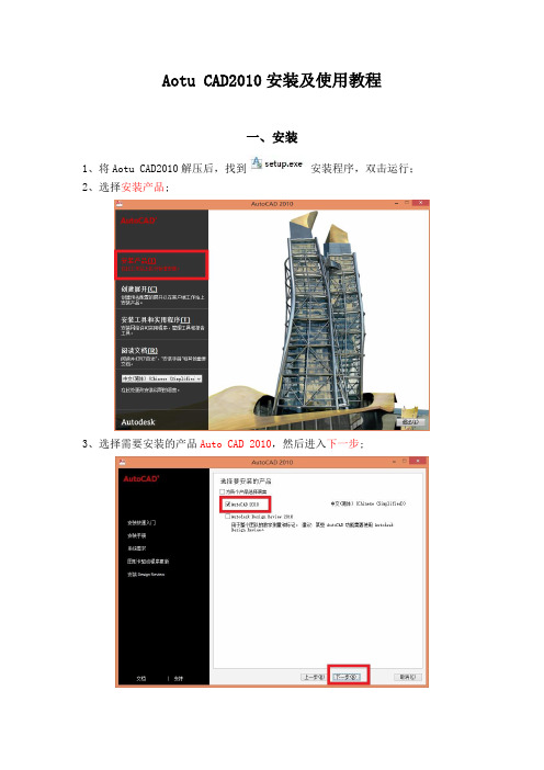
Aotu CAD2010安装及使用教程一、安装1、将Aotu CAD2010解压后,找到安装程序,双击运行;2、选择安装产品;3、选择需要安装的产品Auto CAD 2010,然后进入下一步;4、接受许可协议,选择我接受,进入下一步;5、输入序列号,用户信息,这里序列号为000-00000000,用户信息可以随意输入,然后下一步;6、进入配置选项;7、选择单机许可,进入下一步;8、选择安装类型为典型,安装路径视具体情况而定,接着下一步;9、选择不包含Service pack,进入下一步;10、配置完成,选择配置完成;11、选择安装,开始安装Auto CAD 2010;12、等待组件全部安装完成;13、安装完成,选择完成,退出安装向导;14、双击桌面上的图标,运行AutoCAD 2010;15、提示激活,选择激活;16、复制申请号;17、以管理员身份运行CAD注册机;18、粘贴前面复制的申请号到注册机,点击Mem Patch19、出现Success patched就成功了;20、点击Generate算号,复制激活码;21、粘贴激活码,下一步完成激活;22、激活完成;二、使用1、第一次进入AutoCAD 2010都会进行一个初始设置,在这里直接跳过即可;2、如果你不想下次启动再提醒你,可以去掉AutoCAD 2010下次启动时提醒我前面的勾,然后启动AutoCAD 2010;3、选择不,不再显示此消息,然后确定;4、之后进入AutoCAD 2010软件的界面;5、操作界面的简单介绍;(1)绘图,如果要绘制直线、曲线、圆等形状可以通过绘图板块直接绘制;(2)移动图纸,可以上下左右移动窗口上的图纸,便于查看;(3)图层,在这里可以新建、修改、删除图层;(4)注释,可以通过在这里在图纸内插入文字、表格等信息;(5)特性,通过这里可以修改线条、形状等图案的颜色、线条形状粗细等属性;6、设置文字的格式;通过上面插入文字以后,可以进入文字编辑器里,对文字的大小、颜色、字体等属性进行设置,这里和office差不多;7、绘制直线;(1)可以通过L命令绘制;(2)然后选择一个端点,向你需要的方向延伸,在这里可以直接输入数值,确定线段的长度,也可以拉到你需要的位置;(3)最后回车,确定;8、查看线段的长度;(1)用di命令查看;(2)选择线段的两个端点(3)自动显示出该线段的详细信息;附:CAD常用命令及快捷键一、常用功能键F1: 获取帮助F2: 实现作图窗和文本窗口的切换F3: 控制是否实现对象自动捕捉F4: 数字化仪控制F5: 等轴测平面切换F6: 控制状态行上坐标的显示方式F7: 栅格显示模式控制F8: 正交模式控制F9: 栅格捕捉模式控制F10: 极轴模式控制F11: 对象追踪模式控制二、常用CTRL,ALT快捷键ALT+TK 如快速选择ALT+NL 线性标注 ALT+VV4 快速创建四个视口ALT+MUP提取轮廓Ctrl+B: 栅格捕捉模式控制(F9)Ctrl+C: 将选择的对象复制到剪切板上Ctrl+F: 控制是否实现对象自动捕捉(F3)Ctrl+G: 栅格显示模式控制(F7)Ctrl+J: 重复执行上一步命令Ctrl+N: 新建图形文件Ctrl+M: 打开选项对话框Ctrl+O:打开图象文件Ctrl+P:打开打印对说框Ctrl+S:保存文件Ctrl+U:极轴模式控制(F10)Ctrl+v:粘贴剪贴板上的内容Ctrl+W:对象追踪式控制(F11)Ctrl+X:剪切所选择的内容Ctrl+Y:重做Ctrl+Z:取消前一步的操作Ctrl+1:打开特性对话框Ctrl+2:打开图象资源管理器Ctrl+3:打开工具选项板Ctrl+6:打开图象数据原子Ctrl+8或QC:快速计算器三、尺寸标注DRA:半径标注DDI:直径标注DAL:对齐标注DAN:角度标注END:捕捉到端点MID:捕捉到中点INT:捕捉到交点CEN:捕捉到圆心QUA:捕捉到象限点TAN:捕捉到切点PER:捕捉到垂足NOD:捕捉到节点NEA:捕捉到最近点AA:测量区域和周长(area)ID:指定坐标LI:指定集体(个体)的坐标AL:对齐(align)AR:阵列(array)AP:加载*lsp程系AV:打开视图对话框(dsviewer)SE:打开对象自动捕捉对话框ST:打开字体设置对话框(style)SO:绘制二围面( 2d solid)SP:拼音的校核(spell)SC:缩放比例 (scale)SN:栅格捕捉模式设置(snap)DT:文本的设置(dtext)DI:测量两点间的距离OI:插入外部对象RE:更新显示RO:旋转LE:引线标注ST:单行文本输入La:图层管理器四、绘图命令A:绘圆弧B:定义块C:画圆D:尺寸资源管理器E:删除F:倒圆角G:对相组合H:填充I:插入J:对接S:拉伸T:多行文本输入W:定义块并保存到硬盘中L:直线M:移动X:炸开V:设置当前坐标U:恢复上一次操做O:偏移P:移动Z:缩放。

目录目录 1第1课计算机绘图技术概述 1第2课AutoCAD2010的启动与工作空间的设置 3 第3课AutoCAD 2010的绘图环境 33.1 界面介绍3一、标题栏3二、菜单栏3三、快捷菜单4四、工具栏4五、绘图窗口4六、命令行与文本窗口 5七、状态栏53.2 文件操作5一、创建新图形文件 5二、打开文件5三、保存文件6四、加密保存图形文件 63.3 坐标系7一、笛卡儿坐标系7二、极坐标系7三、相对坐标7四、坐标值的显示73.4 界面设置8一、调整视窗8二、设置绘图单位8三、设置绘图边界9第4课简单图形的绘制104.1直线的绘制10一、绘制直线段10二、绘制射线12三、绘制构造线124.2点的绘制15一、设置点样式:15二、绘制点15三、绘制等分点16四、绘制定距点164.3多边形的绘制16一、绘制矩形16二、绘制正多边形174.4圆及圆弧的绘制19一、绘制圆19二、绘制圆弧21三、椭圆及椭圆弧的绘制24 第5课提高绘图效率295.1 工具栏的设置295.2 视图操作305.2.1重画与重新生成图形30 5.2.2 缩放视图315.3 辅助绘图工具34一、正交绘图35二、设置捕捉35三、栅格工具35四、对象捕捉36五、自动追踪39六、动态输入40第6课复杂图形的绘制416.1 多线416.2 多段线426.3 样条曲线496.4 徒手绘制图形50一、徒手画线50二、绘制修订云线51三、区域覆盖52第7课创建面域和图案填充54 7.1面域547.2 图案填充56第8课图形编辑Ⅰ 608.1选择对象608.2使用夹点编辑图形64一、控制夹点显示65二、使用夹点编辑图形66第8课图形编辑Ⅱ 678.3 删除与复制对象678.4 镜像、偏移和阵列对象708.5 移动、旋转和缩放对象728.6 拉伸、拉长738.7 修剪与延伸对象74第8课图形编辑Ⅲ 76(4)编辑对象特性768.8 打断与合并对象768.9 修改倒角、圆角778.10分解对象与对齐对象788.11编辑对象特性81第9课图层管理849.1 图层概述849.2设置图层的特性。

AS197840The à la Carte Menu: Design Your Own CUIVolker CoccoAutodesk, IncDescriptionThe ability to tailor or customize AutoCAD software has always been the product's strength. Customization can be as easy as creating a personal workspace. Workspaces provide consistency in the workflow, which can make the user more productive. But what about those frequently used commands or functions that aren’t always readily available? Wouldn't it be nice to be able to execute a command macro, which then would execute a series of commands to avoid that repetition? Wouldn’t it be great to have a custom Ribbon panel where one can easily group all of these custom macros? It's easy to do this without programming knowledge by customizing the CUI (customize user interface)—and you can then share that customization with the entire CAD department to improve productivity and enforce CAD standards for all users. In addition to learning how to add commands to AutoCAD and create new tabs and panels for your workspace, you will learn how to add a custom partial menu to the main customization file and add that to an enterprise CUIx.SpeakerEmployed at Autodesk, Inc., as a Technical Support Specialist and AutoCAD KDE (Knowledge Domain Expert) Since 2011, Volker Cocco has been working with AutoCAD software since 1991. He has worked for various Autodesk Resellers since 1997 and has had extensive experience troubleshooting and supporting Autodesk products. With a background in CAD drafting and management, Volker has instructed basic to advanced AutoCAD technical classes including sessions at Autodesk User Group International (AUGI) CAD Camp and Autodesk University.IntroductionAutoCAD has always had a very customizable interface which allowed users to modify their workspace through customization; this could be done through coding or tailoring the toolbars and menus or a combination of both to have the most commonly used tools readily available. Prior to AutoCAD 2006 one would customize the menu system using a text editor which meant that one had to type the code, then compile the menu. If a mistake was made, the user would need to modify the menu and recompile it again. This process changed with the introduction of the CUI (Customized User Interface) in AutoCAD 2006. Autodesk changed the menu format from a text format to an XML (Extensible Markup Language) format which provided a GUI (Graphical User Interface) which let users modify the menu system within AutoCAD and immediately apply and see the changes. With AutoCAD 2010, Autodesk introduced the CUIX in AutoCAD. The CUIX is still the CUI; the difference is that the CUIX was designed for faster loading of the menu system by splitting the content of the CUI and the Ribbon components introduced in AutoCAD 2009 into several files yet containing them all in one compressed container.All that being said; many users will argue that it was simpler to modify the menu system using a text editor. There a pros and cons for both systems; the intent of this lecture is to give you a glossy overview of how easy it can be to customize the user interface for both the workgroup as well as the individual AutoCAD user. To be blunt, one could spend a day talking about all the nuances, components, tweaks and troubleshooting techniques; since this is only an hour long lecture, the handout is designed to give you step by step guides for creating and adding partial menus, creating your own custom commands for your menu, applying those commands to the Ribbon and finally creating a read-only Enterprise menu which cannot be modified.Be sure to download the PowerPoint of the presentation which will have additional content.Getting started – Profiles and SettingsIt’s a good idea to backup settings before beginning any customization as well as afterwards. The following quick topics cover some of the ways you can do this by exporting the AutoCAD profile as well as all other settings such as custom support paths and files. Additionally; when working with profiles you may wish to create Startup switches which will allow you to easily launch AutoCAD with a specific profile among other settings.To Create or Copy the ProfileIn AutoCAD change to an alternate user profile, you can do this as follows:1. At the Command Line, type Options2. In the Options dialog, select the Profiles tab3. In the Profiles tab, select the current profile (there may only be one)4. Click "Add to List" (This allows you to make a copy)5. Give the copy a unique name and click Apply and Close6. Select the newly created profile, Click Set Current7. Click Reset8. Click Apply9. Click OK.To Export a profileIn AutoCAD Export the user profile, you can do this as follows:1. At the Command Line, type Options2. In the Options dialog, select the Profiles tab3. In the Profiles tab, select the current profile (there may only be one)4. Select "Export"5. Give the file a unique name and browse to a preferred location (such as a backup drive)6. Select Save7. Select OK to exit OptionsTo Import a profileIn AutoCAD Export the user profile, you can do this as follows:1. At the Command Line, type Options2. In the Options dialog, select the Profiles tab3. In the Profiles tab, select Import4. Browse to the saved registry file (profilename.arg)5. Select Open6. Select the newly imported profile, Select Set Current7. Click Apply8. Click OK.Exporting and importing custom settingsExport your settings to a file in case you need to reinstall in the future. This export does not back up the application only your settings, but it can be a time saver.Export your settings:Windows 7 Start Menu ->> All Programs ->> Autodesk ->> AutoCAD 2019 ->> Migrate Custom Settings ->> Export AutoCAD 2019 Settings.Importing your settings:Windows 7 Start Menu ->> All Programs ->> Autodesk ->> AutoCAD 2019 ->> Migrate Custom Settings ->> Import AutoCAD 2019 Settings.Windows 10 Operating System: Depending on the build of Windows 10, the programgroups may vary. In most cases selecting the Start button will list the software alphabetically.How to Add a Startup switchTo add switch settings to the shortcut properties, you need to change the command line text associated with the icon or shortcut.To start the program with a command line switch:1. Right-click the program icon on the Windows desktop. Click Properties.2. In the AutoCAD Properties dialog box, on the Shortcut tab, in the Target box, edit theparameters for the switch using the following syntax:"drive:\path\acad.exe" /product ACAD /language "en-US" ["drawing name"] [/switch "name"] [/switch "name"]”For complete information, see the AutoCAD in-product documentation, About Customizing StartupAdding AutoCAD ProfilesA profile is a collection of user settings for AutoCAD or another Autodesk product. Profiles are not used by all products. When you specify a profile on the Specify User Preferences page during the deployment process, it ensures a standard configuration for all computers that use that deployment to install the product.Profiles can contain configuration settings for almost anything that is not a drawing-based system variable. For example, a profile can contain support paths, grip settings, and print settings. Profiles are created on the Profiles tab of the product's Options dialog box. (Excerpt from the CAD Management Guide)1. Type OPTIONS at the command line2. In the Options dialog set the Profiles tab current3. In the Profiles tab select the current profile, then select “Add to List…”4. Name the profile “AU2018E”5. Add description: “Enterprise Profile”6. Select “Set Current”7. Select “Add to List…”8. Name the profile “AU2018M”9. Add description: “Main Profile”10. Set the AU2018M profile current.11. Select “Apply” and “Close” to exit the Options dialogWorking with partial menusAbout Creating and Loading a Partial Customization (CUIX) FileLoading and using a partial CUIX file allows you to create and modify most user interface elements in a separate CUIX file without changing the customization in the main CUIX file.You can create a partial CUIX file to store your user interface customization with the Transfer tab of the Customize User Interface (CUI) Editor. After a CUIX file is created, it can be loaded or unloaded from the Customize tab in the Customize User Interface (CUI) Editor. You can also load and unload CUIX files with the CUILOAD and CUIUNLOAD commands from the Command prompt. The order in which partial CUIX files appear under the Partial Customization Files node in the Customize User Interface (CUI) Editor determines the order they are loaded in to the program. You can rearrange the hierarchy of the items to change the load order.Commands and user interface elements can be added to the main CUIX file or a partial CUIX file that is loaded with the main CUIX file, but not the enterprise CUIX file. Before adding commands to a partial CUIX file, the partial CUIX file must be set as the working CUIX from the Customization Files drop-down list on the Customize tab of the Customize User Interface (CUI) Editor.When a partial CUIX file is loaded, any workspaces defined in the file cannot be used. However, you could transfer a workspace defined in a partial CUIX file to the main CUIX file and then set it current. (AutoCAD Help Documentation)Creating a new partial menu1. Open the CUI (Customize User Interface) Editor2. If necessary, expand the dialog selecting the button on the lower right corner.3. Switch to "Transfer" tab4. Under "Customizations in New File", select, "Create new customization file".5. Save the file to your desired location and name it "AU2018". The CUIX extension isadded automatically.6. In the left pane select the newly created AU2018.CUIX from the drop-down list.7. Expand some of the branches by clicking on the + symbol. The CUIX is empty except forplaceholders.8. The CUIX has been created but it has not been loaded.Loading the partial menu1. In the CUI editor switch to the "Customize" tab2. In the top left pane, under "Customizations in All Files", scroll down and expand "PartialCustomization Files" to view the partially loaded CUIX files.3. Select and Right-Mouse click "Partial Customization Files", then select "Load partialcustomization file".4. Browse to the folder where AU2018.CUIX is located, select the file and select "Open".5. The partial menu will now appear in the Tree View pane.6. Select "Apply" in the CUI editor to save your work.Working with custom commandsThere are numerous way to create custom commands. In this lecture I’m using simple macros. When using macros (as well as more complex coding), syntax is everything. This lecture is not about working with macros although they are being introduced; therefore, I would encourage you to check out the AutoCAD Help documentation for additional information. The section About Command Macros will give you an overview of macro basics.Adding custom commands to the partial menu1. In the "Customize" tab select the "All Customization Files" drop down list and set theAU2018.CUIX current.2. The "Command List:" pane in the lower left corner of the CUI editor is now empty.3. Next to the "All Commands Only" drop down select "Create a New Command".4. In the "Properties" pane on the right, populate the fields as follows:• Name: Z9x• Description: Zoom Extents, Zoom .9x then Save• Extended Help File: <blank>• Command Display Name: Zoom Extents Save• Macro: ^C^C^C_Zoom;E;;.9x;_QSAVE;• Tags: zoom, extents, 9x, save• Images (Small and Large): Z9x.BMP• Select "Apply"5. In the "Command List:" select "Custom Commands" from the drop down list to view thenew command.6. Note: The new command and that it resides in the "AU2018.cuix7. Repeat the procedure for the following command (verify that AU2018.cuix is current):a. ENDPOINT MIDPOINT QUADRANT NODE• Name: OSNAP27• Description: ENDpoint, MIDpoint, QUAdrant and NODe = OSMODE 27• Extended Help File: <blank>• Command Display Name: OSnap EMQN• Macro: 'Osmode;27• Tags: OSMODE,OSNAP• Images (Small and Large): OS27.BMP• Select "Apply"• In the "Command List:" select "Custom Commands" from the drop downlist to view the new command.b. ENDPOINT MIDPOINT CENTER NODE• Name: OSnap15• Description: ENDpoint, MIDpoint, CENter and NODe = OSMODE 15• Extended Help File: <blank>• Command Display Name: OSNAP EMCN• Macro: 'Osmode;15• Tags: OSMODE,OSNAP• Images (Small and Large): OS15.BMP• Select "Apply"• In the "Command List:" select "Custom Commands" from the drop downlist to view the new command.c. Drawing Cleanup• Name: DWGClean• Description: Purge all objects, purge registered applications, run Audit• Extended Help File: <blank>• Command Display Name: Drawing Cleanup• Macro: ^C^C^C_-PURGE;A;;N;;R;;N;_AUDIT;Y;• Tags: Clean, Repair• Images (Small and Large): dwgclean.bmp• Select "Apply"• In the "Command List:" select "Custom Commands" from the drop downlist to view the new command.Working with the RibbonThe Ribbon has a nested structure. The process for adding a command to a panel includes several steps regardless of whether you are using a custom or internal AutoCAD command. First one must create a Tab, then create a panel. Commands need to be added to the panel and the panel needs to be added to the Ribbon tab.Adding Ribbon tabs and panels1. In the "Customize" tab select the "All Customization Files" drop down list and set theAU2018.cuix current.2. Expand the "Ribbon" branch3. Select the "Tabs" branch4. Right-Mouse Click and select "New Tab"5. Name the tab "AU2018 Custom"6. Select the "Panels" branch7. Right-Mouse Click and select "New Panel"8. Name the panel "Utilities”9. Repeat the process to create a panel named “OSNAPS"10. Select "Apply" in the CUI editor to save changesAdding commands to the new panels1. If necessary, set the "AU2018.cuix" current2. Select a command and drag it to the appropriate panel, dropping it in "Row 1"a. Add "Z9x" and “DWGClean” to the "Utilities" panelb. Add "OSNAP27" and "OSNAP15" to the "OSNAP" panel3. Select "Z9x" and in the "Properties" pane change "Button Style" to "SmallWithText"4. Repeat for the remaining custom commands5. Select "Apply" in the CUI editor to save changes6. Add a second row to the "OSNAP" panel7. From the Command List Drag one of the AutoCAD commands such as DSETTINGS anddrop it on the new row8. Note the panel preview9. Drag and drop both panels to the "AU2018 Custom" tab10. Select "Apply" in the CUI editor to save changesAdding the partial menu to your Workspace1. In the "Customize" tab select the "AllCustomization Files" drop down list and set theACAD.cuix current.2. Select the "Workspaces" branch and select"Drafting & Annotation"3. Right-Mouse click and select "Duplicate"4. Rename the Workspace "AU2018 Drafting &Annotation" (Click to edit)5. Right-Mouse click "AU2018 Drafting & Annotation"and select "Set Current"6. Right-Mouse click "AU2018 Drafting & Annotation"and select "Set Default"7. Select "Apply" in the CUI editor to save changes8. Verify that ACAD.cuix is the current customizationfile in the "Customize" tab9. Select the Workspace "AU2018 Drafting &Annotation"10. Note the top right pane in the CUI editor,"Workspace Contents"11. Select "Customize Workspace"12. In the "Customizations in All Files" pane expandthe "Partial Customization Files" branch13. Expand the "AU2018" branch14. Expand the "Ribbon" branch15. Expand the "Tabs" branch16. Select the checkbox next to "AU 2018 Custom"17. Select "Apply" in the CUI editor to save changes18. Close the CUI editor to update the Workspace settings19. Note that the custom tab has been added to the Ribbon20. Select "AU2018" and set the tab current, note the two panels.21. Note that only one command appears on the "AU2018 OSNAP" panel, this is todemonstrate the second row which was added. Select the down arrow next to the paneltitle. Note the location of second command.Modifying the WorkspaceSome settings are easier to change through the User Interface (UI), for example I prefer to have the Properties palette docked to the left and open. Additionally, I like to see what is happening on my Command Line. I’ll make those changes and save them the UI using the WSSAVE command.1. Type WSSAVE at the command line.2. Select "AU2018 Drafting & Annotation" from the "Save Workspace” dialog dropdown tosave the workspace.3. Once the workspace is saved type WSSETTINGS to open the "Workspace Settings"dialog.4. In the dropdown list you can set "My Workspace = "AU2018 Drafting & Annotation" tomake it the default. This is an alternative to the same function which was used in the CUI editor.5. Verify that "Do not save changes to workspace" is selected.6. Select OK7. Test the workspace by switching back and forth between "AU2018 Drafting &Annotation" Workspace and one of the others.Working with the Enterprise CUIXThe Enterprise CUI is intended for a workgroup environment. The intent is for a CAD manager to customize the CUI according to the organizations standards, once customized the cui as an Enterprise file is read only. Any CUI can be made into an Enterprise CUI.Adding an Enterprise CUIX1. Use the CUI Editor to create a new CUI file called AU_User20182. Close the CUI Editor without loading the newly created file.3. Type OPTIONS at the command line4. In the Profiles tab set the AU2018E profile current.5. Switch to the Files tab6. In the tree view pane scroll to and expand “Customization Files” by selecting the (+)plus symbol to the left, then expand “Main Customization File” and “EnterpriseCustomization File”.7. Expand “Main Customization File”8. Select and “Left Mouse click (or press F2 Key) to edit.9. Copy the existing path pointing to the acad.cuix to the Windows Clipboard.10. Browse to the location of your AU_User2018.cuix and select it.11. Select “Open”.12. AU_User2018 will now appear as the Main Customization File.13. Select and “Left Mouse click (or press F2 Key) to edit the pointer (.) for theEnterprise CUI. The “.” Indicates “None”.14. Paste the previously copied path pointing to the acad.cuix. (or browse to its locationand select it)15. Select Apply16. Select CloseTailoring the User workspace with an Enterprise CUIBecause the Enterprise and its partial menus are read-only we will copy the Enterprise workspace to the AU_USER2018.cuix which can then be modified.1. Open the CUI editor2. In the "Customization in All Files" panel3. Locate "ACAD (Enterprise - read-only)4. Select the workspace "AU2018 Drafting & Annotation"5. Right-Mouse click and select Copy6. Scroll up to AU_USER20187. Select "Workspaces"8. Right-Mouse click and select Paste9. The Workspace is added to the AU_USER2018 cui10. Rename the Workspace to differentiate it from the original11. Right-Mouse click the workspace to set it current12. Right-Mouse click the workspace to set it as default13. Select Apply to update the CUI.14. Now that this workspace has been added; in addition to the Enterprise tools the useris able to customize items of their choosing.ConclusionAutoCAD is most powerful when customized for the end-user as well as the organizations standards. As you have seen this was a straight forward process. Keep in mind that when applying this to your organization or if you are customizing a single seat of AutoCAD, that there are many external factors to account for. Always backup configurations and test in a non-production environment.Resources•About Workspace Customization•AutoCAD Classic workspace is not available in AutoCAD 2015 and later - Contains a script which recreates the Classic AutoCAD Workspace •Customization Guide Reference•AutoCAD Customization – Autodesk Discussion GroupIn the “AS197840 - Cocco -AU 2018.zip” you will find the dataset for this session. I’ve also added a supplement from a previous AU sessionwhich I presented. That supplement addresses macros and includesthat sessions dataset as well.。


1、桌面打开AutoCAD2010,之后调整界面右下角“初始设置工作空间”,切换成“AutoCAD经典”模式。
在上面工具栏中“Factory”中选择Factory CAD,点击确定进行加载。
2、加载过后,有八个如下工具栏:①Architectural 建筑工具栏②Package Conveyor包装工具栏③Industrial Objects工业物品工具栏④Automotive Conveyor传送带工具栏⑤Automotive Skid Conveyor滑轮传送带工具栏⑥Power and Free Conveyor自由传送机工具栏⑦Ford Skid Conveyor轨道工具栏⑧Managers工具栏3、以上8中工具栏为常用插件,若深入学习,有所需要,可以在以上插件上右键单击选择所需插件或从CIMFCAD选择。
4、注:在三维图形和二维图形之间的切换:二维——三维,用orbit命令;三维—二维,使用plan命令选C(当前UCS)。
当视图过大或过小时,使用zoom —e命令。
一、建立厂址平面图1、在Architectural插件上选取Column 按钮,会出现Column 对话框。
2、可以选取按钮,指定行列数(试将将厂区分为10行10列)。
3、点击“pick corners”,在平面上画出矩形厂区。
(也可以在已知厂区面积的情况下,设置X,Y的坐标直接画)二、添加机器模块1、在已有插件上点击右键,选取“Block Utilities”插件。
2、选取Block Management按钮,点击Chlib 按钮,从以下路径调入Machine1 图形。
可以在Scale:中选择放大的比例C:\PROGRAM FILES\SIEMENS PLM SOFTWARE\FACTORY PROGRAMS14.0\BAKTUTOR\FACTORYCAD\FTINCH\TUTOR3。
5、点击“确定”后,在厂区图上将该机器放置在合适的位置上。

CAD 2010工作界面CAD 2010简体中文版的工作界面如图1-10所示,主要包括有:标题栏、下拉菜单、绘图区、工具栏、命令栏、状态栏、属性栏等部分。
和其它应用程序一样,用户可以根据需要安排工作界面。
图1-10 中望CAD 2010中文版的界面标题栏:显示软件名称和当前图形文件名。
与Windows标准窗口一致,可以利用右上角的按钮将窗口最小化、最大化或关闭。
下拉菜单:单击界面上方的菜单,会弹出该菜单对应的下拉菜单,在下拉菜单中几乎包含了中望CAD所具有的所有的命令及功能选项,单击需要执行操作的相应选项,就会执行该项操作工具栏:工具栏按类别包含了不同功能的图标按钮,用户只需单击某个按钮即可执行相应的操作。
在工具栏上点击鼠标右键,可以调整工具栏显示的状态。
命令栏:命令栏位于工作界面的下方,当命令栏中显示“命令:”提示的时候,表明软件等待用户输入命令。
当软件处于命令执行过程中,命令栏中显示各种操作提示。
用户在绘图的整个过程中,要密切留意命令栏中的提示内容。
绘图区:绘图区位于屏幕中央的空白区域,所有的绘图操作都是在该区域中完成的。
在绘图区域的左下角显示了当前坐标系图标,向右方向为X轴正方向,向上为Y轴正方向。
绘图区没有边界,无论多大的图形都可置于其中。
鼠标移动到绘图区中,会变为十字光标,执行选择对象的时候,鼠标会变成一个方形的拾取框。
状态栏:状态栏位于界面的最下方,显示了当前十字光标在绘图区所处的绝对坐标位置。
同时还显示了常用的控制按钮,如捕捉、栅格、正交等,点击一次,按钮按下表示启用该功能,再点击则关闭。
CAD命令执行方式在中望CAD中,命令的执行方式有多种,例如可以通过按工具栏上的命令按钮或下拉菜单等。
当用户在绘图的时候,应根据视距情况选择最佳的命令执行方式,提高工作效率。
以键盘方式执行:通过键盘方式执行命令是最常用的一种绘图方法,当用户要使用某个工具进行绘图时,只需在命令行中输入该工具的命令形式,然后根据提示一步一步完成绘图即可。
中望CAD提供动态输入的功能,在状态栏中按下“动态输入”的按钮后,键盘输入的内容会显示在十字光标附近。
图1-11 通过键盘方式执行命令图1-12 动态输入执行命令以命令按钮的方式执行:在工具栏上选择要执行命令对应的工具按钮,然后按照提示完成绘图工作。
以菜单命令的方式执行:通过选择下拉菜单中的相应命令来执行命令,执行过程与上面两种方式相同。
中望CAD同时提供鼠标右键快捷菜单,在快捷菜单中会根据绘图的状态提示一些常用的命令。
图1-13 鼠标右键菜单退出正在执行的命令:中望CAD可随时退出正在执行的命令。
当执行某命令后,可按“Esc”键退出该命令,也可按“Enter”键结束某些操作命令。
注意,有的操作要按多次才能退出。
重复执行上一次操作命令:当结束了某个操作命令后,若要再一次执行该命令,可以按“Enter”键或空格键来重复上一次的命令。
上下方向键可以翻阅前面执行的数个命令,然后选择执行。
取消已执行的命令:绘图中出现错误,要取消前次的命令,可以使用Undo命令,或点击工具栏中的按钮,可回到前一步或几步的状态。
恢复已撤消的命令:当撤消了命令后,又想恢复已撤消的命令,可以使用Redo 命令或点击工具栏中的按钮来恢复。
使用透明命令:中望CAD中有些命令可以插入到另一条命令的期间执行,如当前在使用Line命令绘制直线的时候,可以同时使用Zoom命令放大或缩小视图范围,这样的命令成为透明命令。
只有少数命令为透明命令,在使用透明命令时,必须在命令前加一个单引号“’”,中望CAD才能识别到。
本章小结本章介绍的是中望CAD的最基础内容,中望CAD软件的使用方法和一些主流Windows程序是比较相像的,相信读者在熟悉软件上不用花费太多的力气。
后面几章将详细介绍具体的绘图方法。
CAD设置本章要点⏹启动对话框的使用⏹文件管理⏹定制中望CAD 2010绘图环境⏹设置图形范围、绘图单位⏹中望CAD坐标系统每个人的工作性质、环境,所属专业均不相同,要使中望CAD满足每个人的要求,习惯,应对中望CAD进行必要的设置。
本章的内容,对于初学者可能有点枯燥,请耐心学下去,当然,也可暂时放一放,先从绘图开始学习。
也可以在老师或有经验的同事的帮助下,进行必要的设置。
这里相当于学骑自行车,骑车的初学者,上下车较难,而骑上车,往前骑行相反容易掌握,所以往往是初学者由别人扶上车,再往前骑行。
启动对话框的使用启动中望CAD 2010或建立新图形文件时,系统出现中望CAD 2010屏幕界面,并弹出一个启动对话框,如图2-1所示。
利用该对话框,用户可以方便地设置绘图环境,让用户以多种方式开始绘图。
图2-1启动对话框下面分别介绍各个按钮的功能。
2.1.1 打开一幅图当用户单击图2-1所示的启动对话框中的按钮时,系统弹出一个如图2-2所示的对话框。
如果在对话框右边预览中没有图形,要勾选对话框中的“使用预览”。
用户可以直接点取选择文件列表框下的文件名,单击确定按钮,打开已经存在的图样;或点取浏览按钮,系统将弹出如图2-3所示的选择文件对话框,在该对话框中可选取已有图样,并在其上开始绘图。
例如:在图2-3中,选中中望CAD下面的Sample 子目录中名为Cube.dwg的图形,在对话框右边预览中将可以浏览该图形,然后点取打开按钮,以后就可以在此图样上继续绘图和编辑。
图2-2 打开图形图2-3 通过浏览选择文件2.1.2 使用缺省设置当用户单击图2-1所示的启动对话框中的按钮时,中望CAD 2010将让用户使用缺省的绘图环境开始绘制新图,如图2-4所示。
该对话框中的默认设置框中有两个单选框:英制(英尺和英寸),公制(毫米)。
用户选择其中一项后,单击确定按钮,即可开始绘制新图形。
图2-4 缺省的绘图环境开始绘制新图显然,国内设计技术人员均采用公制。
如果是以英制进入,绘图区是长12英寸,宽9英寸,小数点后带4位小数,一般人肯定不习惯。
而初学者,往往是直接以缺省方式进入,也就是进入英制。
编者认为,最好不采用默认设置方式作新图,好的方式是以样板图为基础的方式,效率是最高。
当然,对于初学者,也不防试一试此项。
如果有困难,可请有经验的人帮助,也可利用其他人作好的样板,甚至在中望CAD中作好样板,也照样可用。
2.1.3 使用样板图向导样板图是指包含一定绘图环境,但未绘任何图形的实体文件。
使用样板图的特点是不仅可以使用它所定义的绘图环境,而且可以使用它所包含的图样数据,以便在此基础上建立新的样板图文件。
样板图文件的后缀名为“Dwt”,中望CAD 2010提供了多个样板图文件供用户选择,同时用户也可以定义自己的样板图文件。
单击图2-1所示的启动对话框中的按钮,打开如图2-5所示的对话框。
中望CAD 2010将让用户打开一幅样板图文件,并且基于该样板图文件绘制新图。
1.选择DWT格式样板图在图2-5所示的对话框中,用户可以在选择样板列表框中选择DWT格式的样板图文件,然后单击确定按钮结束操作。
此后,中望CAD 2010将自动打开该样板图文件并且让用户基于它开始绘制新的图样。
图2-5 基于样板图开始绘制新的图样2.选择DWG格式样板图如果用户在图2-5列表框中没有找到合适的样板图,可以选择【浏览】按钮并点【确定】按钮,则屏幕上将弹出选择样板文件对话框,如图2-6所示,通过该对话框可以查找磁盘目录中DWG格式的图形文件并打开它。
图2-6 基于DWG图形文件绘制新的图样如果采用此方法,有一点要提醒,作图时间将按照原来图形的作图时间,如果是在考试等场合要求有时间限制时,不能使用。
另外一点是容易把原图充掉,而采用样板图,即*.dwt文件,就不会有这方面的担心了。
如果要用一个图形文件作样板图,最好先将其的属性改为只读,可保证一直存在。
2.1.4 使用设置向导图2-7 使用设置向导选项使用向导中包含用户绘图所需的绘图环境。
绘图环境是指在中望CAD 2010中绘制图样所需的基本设置与约定。
能够使绘图实现专业化、用户化和流水线作业,同时它可大大提高绘图效率,使所绘制的图形符合相关专业要求。
在中望CAD 2010中,绘图环境主要包括以下内容:◆绘图单位、测量精度、光标捕捉等。
◆图纸大小与布局、绘图界限等。
◆文字与尺寸格式。
◆线型和图层颜色、线型、图层等。
启动对话框中的使用设置向导选项可实现以上部分内容的设置。
选择启动对话框中的按钮,系统弹出如图2-7所示对话框,且在选择向导列表框中显示两个选项:高级设置与快速设置。
在该列表框下方向导说明区域中将显示当前向导功能的描述文字,下面分别介绍这两种设置。
1.高级设置图2-8 高级设置对话框在设置向导对话框中,点取选择向导列表框下的高级设置选项,再点取确定按钮,将进入高级设置状态,系统将弹出一个高级设置对话框,如图2-8所示。
该向导共有五项设置,即:1)单位:设置绘图单位和精度。
如图2-8所示,中望CAD 2010共提供了五种绘图单位,其缺省为十进制,也就是小数,一般也是采用十进制。
但精度不能采用缺省值0.0000,一般初学者可选0即可。
2)角度:设置角度和精度。
类似单位设置,缺省为第一项,可选度/分/秒(S)这一项,比如斜齿轮。
3)角度测量:测量角度的起始方向。
选缺省项正东,也就是时针三点方向。
4)角度方向:角度测量方向。
缺省项为逆时针方向。
角度的起始和方向都和我们从小学开始学习的数学完全相同。
5)区域:绘图区域设置。
分别在宽度和长度键入绘图区域的大小。
比如A3图纸为420*297,A4图纸为*297*210等。
完成以上五步后,点取完成按钮,即完成高级设置,接着开始绘图工作。
2.快速设置如图2-7所示的对话框,在选择向导列表框中选择快速设置选项,再点取确定按钮,系统将弹出快速设置对话框,如图2-9所示。
快速设置较高级设置简单得多,在快速设置对话框中只有单位和绘图区域两项设置,同高级设置。
在单位设置中,小数精度,对于初学者其精度选为0已足够了,清爽,好理解,就是在工程上,公称尺寸大多以毫米(mm)为准,在建筑上,精确到毫米足矣。
如图2-9所示。
图2-9 快速设置对话框2.2 文件管理命令前面介绍了开始对话框及其使用,下面将讲述中望CAD 2010常用文件管理命令。
中望CAD 2010中常用的文件管理命令有NEW、OPEN、QSAVE/SAVEAS、QUIT等。
2.2.1 创建新图形1.以缺省设置方式新建图形在工具栏中选择“新建”图标,或在命令行中直接键入“NEW”,即可以缺省设置方式创建一个新图形。
该图已预先作好了一系列设置,例如绘图单位,文字尺寸及绘图区域等。
你可根据绘图需要保留或改变这些设置。
2.使用启动对话框新建图形执行NEW命令后,系统会弹出启动对话框。
该对话框允许以三种方式创建新图,即使用缺省设置、使用样板图向导及使用设置向导。