Power distribution design for high-rise building fire
- 格式:doc
- 大小:87.50 KB
- 文档页数:11

E D AOnBoard Technology June 2004 - page 58Power Distribution System Design For High Speed BoardsThe integrity of Power Distribu-tion Systems (PDS) is becoming very critical as the clock frequen-cies and power consumption of high-end ASICs/microprocessors continue to increase rapidly. In fact, as more functionality is in-tegrated into modern ASICs and high-end microprocessors, they are consuming increasingly more power than ever before. This fact, coupled with faster operating fre-quencies and shorter clock edge rates, make the design of PDS ever more challenging. Moreover, as the core supply voltages are low-ered to around a volt and half, only very small percentage of ripple on the Power Supply voltages can be tolerated.Consider the following example: a high end processor or a modern Network Search Engine ASIC will have transient power requirements of 25A on a supply of 1.6V/1.2V with total allowable ripple voltage less than 60mV over a frequency range of DC to a hundreds of MHz. The PDS design should be ad-equate to cater to the power sup-ply needs of the devices over a wide frequency spectrum. Failing to do so, the high speed boards would behave unpredictably. In general, the PDS design for high speed and high transient power boards extends beyond just decoupling by thumb rules which is often the only design measure considered adequate.Design methodology There are two design method-ologies or approaches that can be followed for PDS design: empiri-cal and tool (Cadence Specctra-quest)-based. The criteria for both approaches is to set target imped-ances that need to be met over the complete frequency spectrum of interest, ranging from DC to sev-eral hundreds of MHz. References to practical experiences with a live project, that used Spectraquest power integrity tool, are made wherever relevant.Target impedance Target impedance is defined as the ratio of voltage tolerance to tran-sient current. For example: for a supply voltage of 1.2V with 5% maximum ripple tolerance require-ment and transient current of 20A,the target impedance will be 3m Ω (1.2 X 5%/20A). The PDS should have an impedance less than the target impedance over the entire frequency spectrum of interest or the upper cut off frequency. The upper cut off frequency is deter-mined by thefrequency that cannot escape the substrateparasitics of the device. Accord-ing to the generalrule of thumb,this is half the rise time of the transient current pulse. Thus if the transient cur-rent pulse has a rise time of 1ns, the upper cut-off frequency could be 500MHz. This limit could be further reduced by the substrate parasitics and varies from device to device.The PDS consists of switching regulators or voltage regulator modules (VRM), decoupling ca-pacitors, PCB and the device being decoupled, by virtue of its ability to filter out high frequency noise through substrate parasitics. Each of the above components of the PDS has a sphere of influence in a particular frequency band, as il-lustrated in Figure 1.The high current switching power supplies, with their slow load re-sponse times (typically of an A/µs), are effective from low frequencies to over hundreds of KHz.Bulk capacitors are effective from hundreds of KHz to a couple of by Vishnu Jwalapuram,WiproFigure 1 – Sphere of influence of components in particular frequency bandsFigure 2 – Loop formed by capacitor ESL, power planes, vias and connecting tracesE D AOnBoard Technology June 2004 - page 59MHz. In this range of frequencies, the equivalent series resistance (ESR) ofthe capacitors plays a dominating role with respect to the other parasitics. Capacitors with low ESR, high capacitance and flat impedance response are preferred. Several vendors offer multiple anode capacitors with very low ESR, less than 10m Ω, which exhibit excellent flat imped-ance versus frequency response. The amount of bulk capacitance required in this frequency range iscalculated by:C = I dt/dVwhere dt is the slowest rise time ofthe transient current. For example if there is a load transient current requirement of 20A to which the switching supply responds in 20µs and the PDS must remain within 5% of the supply voltage of 1.2V, this requires a bulk capacitance of 6666µF to supply the required current to the load as the power supply ramps up. The user needs to use several bulk capacitors in parallel to meet the capacitance value and the combined ESR of the combi-nation to meetthe target im-pedance.Ceramic ca-pacitors play a dominantrole in the fre-quency range from several tens of MHz to hun-dreds of MHz. Capacitors with low equivalent series inductance (ESL) should be chosen for effective de-coupling in this frequency band. The maximum allowable Induc-tance in this frequency range is given by:L = V dI/dtwhere dt is the fastest rise time of the transient current. For a tran-sient current requirement of 20A with rise time of 1ns and with PDS that must remain within 5% of the supply voltage of 1.2V, the maxi-mum allowable inductance is 3pH. PCB Power and GND plane pairs filter frequencies from close to a GHz and over, as they form em-bedded capacitance.Mounted inductance The mounted Inductance of the loop formed by the capacitor ESL,power p lanes, v iasand the connect-ing traces need to be minimisedfor the effective performance of the PDS at high frequencies. The ESL referred to above is only a part of the total loop inductance of the PDS as shown in Figure 2.Thecapacitor ESL can be minimised by choosing capacitors with low ESL from dif-ferent vendors. The length of the traces connecting the capacitor pads to the vias can be minimised either by building the via in the pads or routing the traces (Figure 3). Conventional routing of the traces from the capacitor pads to the vias (parallel to the length of capacitor) will increase the loop area. Though vias in the pad are a better option, this solution comes with an additional premium in terms of manufacture and assem-bly of the board. Mounted induc-tance can also be minimised by us-ing a PCB stack up that has Power and GND planes adjacent to the component layer.One of the following approaches can be followed for the design of PDS.Empirical approachThis is a simple and less time consuming approach and suits the majority of applications. With this approach, the target imped-ance of the PDS based on the load transient current requirement is determined first and then the necessary bulk capacitance for the lowest frequency component is calculated. For bulk capacitors, high capacitance, low ESR capaci-tors should be chosen to reduce ripple voltages. The maximum al-lowable inductance for the highest frequency component (fastest rise time) of the circuit must be found, and capacitors with the lowestESL must be chosen to reduce theFigure 3 – Mini-mising the length of traces con-necting capacitor pads to vias Figure 4 – Results of Single-Node simulation for a 1.2V power plane, 20A transient current and 5% ripple toler-ance Figure 5 – Results of a Multi-Node simulationE D AOnBoard Technology June 2004 - page 60number needed in parallel to meet the target impedance.Approach using Specctraquest The power distribution analyses can be done using the Cadence Specctraquest Power Integrity tool. The tool supports two simu-lation modes, Single-Node and Multi-Node simulations, akin to pre-layout and post-layout simu-lations of signal integrity. The Single-Node simulation validates whether the number of capacitors that have been chosen can main-tain the target impedance over the frequency band of interest. Al-though decoupling capacitors over entire frequency range are consid-ered in Single-Node simulations, their placement is not. Multi-Node simulation considers the place-ment of decoupling capacitors, board stack up, mounted induc-tance, loop inductance as well as noise source and power supply module placement.The output of a Single-Node simu-lation is a BOM-like report of ca-pacitors and a graph showing the response of the PDS over a range of frequencies. The output of the Multi-Node simulations is a graph showing the response of PDS after capacitor placement. The criterion for satisfactory performance is to get all the curves in the graph below the target impedance. The graph of Figure 4 shows the re-sults of Single-Node simulation for a 1.2V power plane, 20A transient current, 5% ripple tolerance.The blue graph shows the imped-ance of the power plane withoutthe decoupling capacitors andthe black one shows the imped-ance after considering the effectof the decoupling capacitors and the response of the switching sup-ply or VRM. The cut off frequency is shown by the dotted line and stands at 276MHz. The Single-Node simulation doesn’t take into account the placement and the corresponding parasitics, which include the ESL and mounted in-ductance.Table 1 shows some of the impor-tant parameters of the report filegenerated from Single Node simu-lations. The Single-Node simulation gives a complete list of decoupling capaci-tors that need to be placed around the device in question (Table 2). Once the Single-Node simulation has been performed and the tar-get impedance requirements are met, all the capacitors need to beplaced around the device being decoupled. The Multi-Node simu-lations need to be performed after placing all the capacitors around the device.The graph of Figure 5 shows the results of a Multi-Node simula-tion. Multi-Node simulations take into account the capacitors and the transient current sourceplacement, parasitics, including mounted inductance, ESL and the effective decoupling radius of the capacitor etc. The tool divides theentire power plane area around thedevice into zones or grids and pro-duces a wave for each of the zones (the graph reports many of these waves). These zones are user de-fined rectangular or square areas on the power plane. If the wave is under the target impedance in the graph, the decoupling is adequate for that particular zone. If any one of the waves exceeds the target impedance limit, as shown in thegraph, the capacitors need to bere-arranged to keep the impedancebelow this limit. The Power Integ-rity Analyses on the device need tobe performed at the beginning ofthe layout phase, before routing.Practical considerations The question of when to do the comprehensive Power Integrity Analyses using EDA tools is a tricky issue. One guideline is the differ-ence in the rate at which the power supply responds to the transient load current requirement. Gener-ally all the switching power sup-plies respond slowly (in an A/µs) against several Amps per nanosec-ond requirements of advanced high end ASICs or microprocessors.Another important practical con-sideration is the limit imposed by the vendor on the total capacitanceand the combined ESR at the in-ternal switching frequency of the power supply at the output of the module. EDA tools may not con-sider this limit and, exceeding it,may break the power supply intooscillations.The cost of decoupling is another factor that should be taken into consideration right from the start of ASIC design stage. For example decoupling a 20A/ns transient cur-rent (with a power supply respond-ing in 20µs) requires close to 600 caps to filter the frequencies up to 300MHz on the board. This could add up an additional cost for de-coupling. Table 1 – Important parameters from the report generated from a Single-Node simulationTable 2 – Sample table of decoupling capacitors.。

PDB-8F8R Power Distribution for Access Control with Fire Interface moduleSecuritron Magnalock CorporationstDoc.# 500-33045 Rev. A: Installation specifications subject to change without noticeASSA ABLOY, the global leader in door opening solutions.Phone: (800) MAGLOCK***************************PDB-8F8R Power Distribution for Access Control with Fire Interface module Controls and Distributes Power with 8 Control Relays with an EOL Fire trigger Interface Power Interface for Access Control, CCTV, Fire, HVAC, Elevator,and general low voltage system controlNote: Fire, HVAC and Elevator Control has not been evaluated by ULFeatures:∙8 Heavy duty Relays with individual Inputs and Status LED’s∙Each Relay Input can be Activated from Low Current Open Collector,Normally Closed or Normally Open Switch∙EOL End of Line Resistor Fire Interface Master Trigger de-energizes allOutput Relays that are Enabled∙Universal 11 – 27.5Vdc power input∙Available with Fuses or PTC Circuit BreakersNote: Only the 500mA fuse version of the board has been evaluated by ULNote: The outputs of the PDB-8F8Rare power limited when connected tothe AQD3 power-Limited power supply∙Each Output may be Individually Configured for:o Fire Trigger (FT) Enabled or (FTD) Disabledo FUSE model can provide optional Dry Contactso N/O or N/C Option Configures the Relay Switched Output∙Each Output 1-8 has a protected, continuous Output and a Relay controlledOutput∙TRG LED Green Indicates Trigger Status∙Control Power and Main Lock Power may be Isolated(Separate Power Supplies) at Users OptionNote: Dual/separate power source configuration has not been evaluated by UL andcannot be configured for UL Listedproducts∙All Terminal Blocks are Pluggable by Channel & Function∙Made in the USA with a Lifetime WarrantyDescription / InstructionsThe PDB-8F8Ris a versatile, compact way to distribute and control power for Access Control Systems with Fire Alarm Interface. The PDB-8F8Ris an 8 position power distribution board with individual Relays with input (IN) control for each output (OUT). An EOL resistor triggerinput (TRIG), will force all output relays to de-energize that are selected (FT). In a typical installation, the TRIG would be connected to a Fire Alarm panel via a set of contacts. When the Fire Alarm trips, all enabled relays would be forced to be de-energized to unlock electric doors, shut down air systems, and or return elevators to ground floor.Input / Output Terminals, Jumpers and LEDDetails and SpecificationsControl Power (- CONTR +) Two position un-pluggable terminal block is used to power the coils of the relays. The control voltage must be between 11 and 27.5 Vdc. Each relay energized will draw 20ma of current. By default, Control Power and Main Power are connected together with jumpers J1 & J2 so no connection would be made here unless you were using Dual/separate power as described below. Note Dual/separate power source configuration has not been evaluated by UL and cannot be configured for UL Listed products.Main Power (- POWER +) Two position un-pluggable terminal block provides the power to the outputs to be distributed and power to Control through J1 & J2. In anormal application the Power must be between 11 and 27.5 Vdc and would be connected here.Dual/Separate Power J1 & J2 Jumpers Note Dual/separate power source configuration has not been evaluated by UL and cannot be configured for UL Listed products. J1 Connects (-) Power to (-) Control, J2 Connects (+) Power to (+) Control. By default J1 & J2 are connected together. When J1 & J2 are cut, you must supply 11 to 27.5Vdc to Control power, then you may connect any voltage to 32V AC or DC to the Main Power Terminals. See Dual/Separate Power application figure below.Inputs (1-8 IN C) Eight, two position un-pluggable terminal blocks. When IN & C are shorted together, the like number output relay will energize. Each relay can also be energized by an open collector that is common to thecontrol power, sinking 20ma for each input. Each of the C’s (common) are connected to control negative power. Input LED’s (1-8) Whenever an input is active (relay energized) the associated input red LED will illuminate.FDT/FT (1-8) Jumpers - These are three pin headers adjacent to each fuse with a shunt with handle that shorts the center pin to FTD or FT.FTD = Fire Trigger Disabled - When selected, theTrigger will not effect that output.FT = Fire Trigger – When selected Triggering will force that Input Relay to De-Energize.Dry/Wet Option (1-8 Fuse Models) Through a Fuse, the (+ Power) is connected to the swing arm of each Relay to distribute power to its output. Removing the Fuse, removes the power from the relay. The (+) now becomes the Common Swing Arm and the “O” is the N/O or N/C contact as selected with jumper.Outputs (1-8 OUTPUT C, +, O) Eight, Three position un-pluggable terminal blocks. “C” is Power Common and is connected to (- power). “+” is connected to fused (+power) and the relay swing arm. “O” is the relay switched output as selected with N/O or N/C selector jumperOutput Relay Contacts Selector (1-8 NC/NO) Jumpers These 3 pin headers with shunt selectors are located just above each output which selects whether the N/C or N/O contacts are connected to the “O” switched output terminal. With N/C selected, output would be normally ON, or connected to swing arm. With N/O selected, output would turn ON, or close when input is activated. Fire Alarm Interface Trigger (2.2K EOL TRIG) Two position un-pluggable terminal block. This input must see the 2.2K ohm EOL (End Of Line) resistor to be in the normal condition. The EOL is to be placed in a Listed fire alarm panel. See Fig 1 illustrating that shorting or opening the EOL will cause the PDB-8F8R to trigger.TRIG LED (TRIG) Green LED normally ON. Whenever the Trigger is active the LED will be OFF.Ordering InformationPDB-8F8R “ACI” module only with 500ma Fuses Note: Only the 500ma fuse version of the board has been evaluated by UL No other fuse size or PTC’s can be used with a AQD3 .SpecificationsControl (-contr+) ........................... 11–27.5Vdc @ 160mA Normally no connection is made here. Note: You must add this current to your total device load calculations to be sure your load will be within the rating of the power supply as configuredMain Power (-power+) .................................... 11-27.5Vdc Note: Must cut J1 & J2 when not using 11-27Vdc power See Dual/Separate power source configuration NoteDual/separate power source configuration has not been evaluated by UL and cannot be configured for UL Listed products.Total Amps would be equal to the total current of the outputs load plus the module draw of 160ma Fused/Wet Outputs (12v operation):Max. Output Current..................330mA,12V (each output) 2.64 A (total all outputs)Fused/Wet Outputs (24V (each output):Max. Output Current .............. 155mA, 24V (each output): 1.24 A (total all outputs)Dry Outputs:Max. Output Current ............................................ 3A, 30V As evaluated with UL with 500ma fusesTerminal blocks un-pluggable... 5mm spacing 14–22 awg Fused Outputs 1-8 .............................................. 500mA Littlefuse P/N 217.500 20mm replacementThe fused outputs of the PDB-8F8Rare power limited when connected to the AQD3 power-Limited power supply Output Relays 1-8 Dry Contacts are not to exceed ................................................................... 7A or 100VA Trigger Input .................................................... 2.2K EOL Operating Temperature .................................. 0o to+49o C Mounting Holes ......................................... (4) 3.4” x 4.5” Module Size: ................................ 4.82”w x 3.84h x 1.4”d Weight: ..................................................................... 8oz Mounting Note: Secure 4, #6-32 female/female hex standoffs 7/16” long onto 4, #6-32 studs provided in distribution option space to the right of AQD3 inside E-1485 cabinet back. Place PDB-8F8Ron stand offs with input terminals on top. Secure module with 4, #6-32 x ¼” pan head screws. No metal hardware should be larger than .28” in Diameter.Note: All interconnected devices must be UL Listed.UL Approvals for PDB-8F8RUL 294 Access Control System UnitPDB-8F8R Typical ApplicationsSingle Power Source Application Fig 1Dual/Separate Power Supplies Fig 3。

T h e i n f o r m a t i o n p r o v i d e d i n t h i s d o c u m e n t a t i o n c o n t a i n s g e n e r a l d e s c r i p t i o n s a n d /o r t e c h n i c a l c h a r a c t e r i s t i c s o f t h e p e r f o r m a n c e o f t h e p r o d u c t s c o n t a i n e d h e r e i n .T h i s d o c u m e n t a t i o n i s n o t i n t e n d e d a s a s u b s t i t u t e f o r a n d i s n o t t o b e u s e d f o r d e t e r m i n i n g s u i t a b i l i t y o r r e l i a b i l i t y o f t h e s e p r o d u c t s f o r s p e c i f i c u s e r a p p l i c a t i o n s .I t i s t h e d u t y o f a n y s u c h u s e r o r i n t e g r a t o r t o p e r f o r m t h e a p p r o p r i a t e a n d c o m p l e t e r i s k a n a l y s i s , e v a l u a t i o n a n d t e s t i n g o f t h e p r o d u c t s w i t h r e s p e c t t o t h e r e l e v a n t s p e c i f i c a p p l i c a t i o n o r u s e t h e r e o f .N e i t h e r S c h n e i d e r E l e c t r i c I n d u s t r i e s S A S n o r a n y o f i t s a f f i l i a t e s o r s u b s i d i a r i e s s h a l l b e r e s p o n s i b l e o r l i a b l e f o r m i s u s e o f t h e i n f o r m a t i o n c o n t a i n e d h e r e i n .Product data sheetCharacteristicsMETSEPM2120EasyLogic PM2120, Power & Energy meter,up to the 15th harmonic, LED display, RS485,class 1MainRange EasyLogic Product name EasyLogic PM2100Device short name PM2120Product or component typePower meterComplementaryDevice application Sub billingPower monitoring Power quality analysis Total harmonic distortion Up to the 15th harmonicType of measurementApparent power min/max, totalActive and reactive power min/max, total Current min/max, avg Voltage min/max, avg Frequency min/max, avgTotal current harmonic distortion THD (I) per phase Total voltage harmonic distortion THD (U) per phase Power factor min/max, avg Apparent energy totalActive and reactive energy totalMetering typeCurrent I, I1, I2, I3Peak demand power PM, QM, SMActive, reactive, apparent energy (signed, four quadrant)Peak demand currents Active power P, P1, P2, P3Calculated neutral currentVoltage U, U21, U32, U13, V, V1, V2, V3Unbalance currentReactive power Q, Q1, Q2, Q3Demand power P, Q, SApparent power S, S1, S2, S3Accuracy classClass 1 active energy conforming to IEC 62053-21Class 1 reactive energy conforming to IEC 62053-24Class 5 harmonic distorsion (I THD & U THD)Measurement accuracyApparent power +/- 1 %Active energy +/- 1 %Reactive energy +/- 1 %Active power +/- 1 %Voltage +/- 0.5 %Power factor +/- 0.01Current +/- 0.5 %Frequency +/- 0.05 %Measurement current 5…6000 mAMeasurement voltage35…480 V AC 50/60 Hz between phases20…277 V AC 50/60 Hz between phase and neutral 480…999000 V AC 50/60 Hz with external VT Frequency measurement range 45…65 Hz[Us] rated supply voltage44...277 V AC 45...65 Hz +/- 10 %44...277 V DC +/- 10 %Network frequency50 Hz60 HzRide-through time100 Ms 120 V AC typical400 Ms 230 V AC typical50 ms 125 V DC typicalLine Rated Current1 A5 AMaximum power consumption in VA6 VA 277 V ACMaximum power consumption in W 3.3 W (power lines (AC))2 W at 277 V (power lines (DC))Input impedance Current (impedance <= 0.3 mOhm)Voltage (impedance > 5 MOhm)Tamperproof of settings Protected by access codeDisplay type7 segments LEDDisplay colour RedMessages display capacity 3 fields of 4 charactersDisplay digits12 - 0.56 in (14.2 mm)Demand intervals Configurable from 1 to 60 minInformation displayed Demand current (past value)Demand current (present value)Demand power (past value)Demand power (present value)VoltageCurrentFrequencyEnergy consumptionHarmonic distortionPower factorActive powerApparent powerReactive powerUnbalanced in %Control type 3 x buttonLocal signalling Red LED: output signal 1...9999000 pulse/ k_h (kWh, kVAh, kVARh)Green LED: module operation and integrated communicationNumber of inputs0Number of outputs0Communication port protocol Modbus RTU 4800 bps, 9600 bps, 19200 bps, 38.4 Kbps even/odd or none - 2wires 2500 VCommunication port support Screw terminal block: RS485Data recording Time stampingMin/max for 8 parametersFunction available Real time clockSampling rate64 samples/cycleCybersecurity Enable/disable communication portsCommunication service Remote monitoringProduct certifications CE IEC 61010-1CULus UL 61010-1CULus conforming to CSA C22.2 No 61010-1RCMEACC-TickMounting mode Clip-onMounting position VerticalMounting support FrameworkProvided equipment 1 x Installation guideMeasurement category Category III 480 VCategory II 480…600 VElectrical insulation class Double insulationClass IIFlame retardance V-0 conforming to UL 94Connections - terminals Current transformer screw connection bottom) 6Voltage inputs screw connection top) 4Material PolycarbonateWidth 3.78 in (96 mm)Depth Total 3.00 in (76.09 mm)Embedded 2.43 in (61.64 mm)Height 3.78 in (96 mm)Net Weight10.58 oz (300 g)Compatibility code PM2120EnvironmentService life7 year(s)IP degree of protection IP54 front: conforming to IEC 60529Body IP30 IEC 60529Relative humidity5…95 % 122 °F (50 °C)Pollution degree2Ambient air temperature for operation14…140 °F (-10…60 °C)Ambient air temperature for storage-13…158 °F (-25…70 °C)Operating altitude<= 6561.68 ft (2000 m)Electromagnetic compatibility Electrostatic discharge conforming to IEC 61000-4-2Radiated radio-frequency electromagnetic field immunity test IEC 61000-4-3Electrical fast transient/burst immunity test conforming to IEC 61000-4-4Surge immunity test IEC 61000-4-5Conducted RF disturbances conforming to IEC 61000-4-6Magnetic field at power frequency conforming to IEC 61000-4-8Voltage dips and interruptions immunity test IEC 61000-4-11Emission tests conforming to FCC part 15 class AOvervoltage category IIIOrdering and shipping detailsGTIN03606480800146Nbr. of units in pkg.1Package weight(Lbs)10.67 oz (302.5 g)Packing UnitsUnit Type of Package 1PCEPackage 1 Height 3.78 in (9.6 cm)Package 1 width 2.65 in (6.72 cm)Package 1 Length 4.00 in (10.16 cm)Unit Type of Package 2BB1Number of Units in Package 21Package 2 Weight14.25 oz (404 g)Package 2 Height 4.53 in (11.5 cm)Package 2 width 3.43 in (8.7 cm)Package 2 Length 4.72 in (12 cm)Unit Type of Package 3S03Number of Units in Package 318Package 3 Weight17.04 lb(US) (7.73 kg)Package 3 Height11.81 in (30 cm)Package 3 width11.81 in (30 cm)Package 3 Length15.75 in (40 cm)Offer SustainabilitySustainable offer status Green Premium productREACh Regulation REACh DeclarationEU RoHS Directive Compliant EU RoHS DeclarationMercury free YesRoHS exemption information YesChina RoHS Regulation China RoHS DeclarationEnvironmental Disclosure Product Environmental Profile Circularity Profile End Of Life Information。

AILiꎬetal.AnalysisofGreenandLowCarbonTechnologyofMulti ̄storeyandHigh ̄riseFactoryBuildings7 结语本文基于工业上楼的背景ꎬ以 绿色低碳 为导向ꎬ本着 减少厂房建筑能耗 和 提升人员办公舒适性 的原则ꎬ结合多高层厂房运营使用的潜在问题ꎬ针对 声环境设计㊁光环境设计㊁风环境设计㊁热环境设计㊁可再生能源设计 提出绿色低碳技术ꎬ通过模拟分析ꎬ验证了技术的可行性ꎬ将绿色建筑的理念与工业建筑结合起来ꎬ使多高层厂房不再是一个单一的生产空间ꎬ而可以是舒适的办公活动场所ꎮ碍于篇幅和研究的局限性ꎬ本文提出的绿色设计策略侧重对原理的阐述ꎬ缺少相关参数的定量分析ꎬ希望在后续的研究中可以进一步量化相关技术的影响ꎬ为多高层厂房的节能减排和舒适健康目标提出更加详细具体的参考意见ꎮ参考文献:[1]中国建筑节能协会.2022中国城乡建设领域碳排放系列研究报告[R].北京ꎬ2022.[2]周国义ꎬ林伟ꎬ周书东ꎬ等.绿色生态导向的 工业上楼 设计研究 以东莞松湖智谷产业园为例[J].重庆建筑ꎬ2022ꎬ21(9):13-14.[3]08J931ꎬ建筑隔声与吸声构造[S].2008.[4]康玉成.实用建筑吸声设计技术[M].北京:中国建筑工业出版社ꎬ2007.[5]周治宏.重庆单层厂房天窗优化设计策略研究[D].重庆:重庆大学ꎬ2015.[6]吕帅ꎬ林波荣.基于天然采光性能的建筑中庭形体设计导则研究[J].南方建筑ꎬ2018ꎬ(2):55-59.[7]闫玮.建筑自然采光与空间组织策略[J].建筑技艺ꎬ2009ꎬ(6):94-97.[8]陈益明ꎬ胡晓峰ꎬ田智华ꎬ等.苏州某办公厂房的绿色建筑亮点技术分析[J].绿色建筑ꎬ2013ꎬ5(5):37-40.[9]白胜芳.建筑遮阳技术[M].北京:中国建筑工业出版社ꎬ2013.[10]张康.绿色工业建筑风环境设计研究[D].苏州:苏州科技大学ꎬ2016.[11]宋宇辉ꎬ曲冠华ꎬ原野ꎬ等.高层办公建筑风环境性能优化设计研究与实践[J].建筑节能ꎬ2020ꎬ48(10):39-45.[12]吴梅艳ꎬ欧阳金城ꎬ刘艳华.工位空调研究的现状及前景[C]//中国制冷学会2009年学术年会ꎬ中国天津ꎬ2009.[13]倪欣ꎬ鲍茂超ꎬ白国强ꎬ等.绿色技术在西安某工业建筑中的应用[J].工业建筑ꎬ2017ꎬ47(1):184-187.[14]罗涛ꎬ魏振力ꎬ杨玺.光伏建筑一体化(BIPV)在工业厂房的应用分析[J].智能建筑与城市信息ꎬ2021ꎬ(1):70-71.[15]王文举.工业建筑隔声技术的应用探讨[J].建筑工程技术与设计ꎬ2018ꎬ(8):5576.作者简介:艾荔(1994)ꎬ女ꎬ重庆人ꎬ毕业于东南大学ꎬ建筑学专业ꎬ硕士研究生ꎬ研究方向:绿色建筑(twinkleaili@126.com)ꎮә通讯作者:唐可峙(1973)ꎬ男ꎬ重庆人ꎬ毕业于天津大学ꎬ正高级工程师ꎬ研究方向:建筑设计㊁智能建筑㊁绿色建筑(1050131489@qq.com)ꎮinterpretableenergydataimputationmodelsusingbuildingphysicsinsightbyAntonioLiguoriꎬMatiasQuintanaꎬChunFuꎬetalꎬArticle114071Abstract:Missingdataarefrequentlyobservedbypractitionersandresearchersinthebuildingenergymodelingcommunity.Inthisregardꎬadvanceddata ̄drivensolutionsꎬsuchasDeepLearningmethodsꎬaretypicallyrequiredtoreflectthenon ̄linearbehavioroftheseanomalies.AsanongoingresearchquestionrelatedtoDeepLearningꎬamodel sapplicabilitytolimiteddatasettingscanbeexploredbyintroducingpriorknowledgeinthenetwork.Thissamestrategycanalsoleadtomoreinterpretablepredictionsꎬhencefacilitatingthefieldapplicationoftheapproach.ForthatpurposeꎬtheaimofthispaperistoproposetheuseofPhysics ̄informedDenoisingAutoencoders(PI ̄DAE)formissingdataimputationincommercialbuildings.Inparticularꎬthepresentedmethodenforcesphysics ̄inspiredsoftconstraintstothelossfunctionofaDenoisingAutoencoder(DAE).InordertoquantifythebenefitsofthephysicalcomponentꎬanablationstudybetweendifferentDAEconfigurationsisconducted.FirstꎬthreeunivariateDAEsareoptimizedseparatelyonindoorairtemperatureꎬheatingꎬandcoolingdata.ThenꎬtwomultivariateDAEsarederivedfromthepreviousconfigurations.EventuallyꎬabuildingthermalbalanceequationiscoupledtothelastmultivariateconfigurationtoobtainPI ̄DAE.Additionallyꎬtwocommonlyusedbenchmarksareemployedtosupportthefindings.ItisshownhowintroducingphysicalknowledgeinamultivariateDenoisingAutoencodercanenhancetheinherentmodelinterpretabilitythroughtheoptimizedphysics ̄basedcoefficients.WhilenosignificantimprovementisobservedintermsofreconstructionerrorwiththeproposedPI ̄DAEꎬitsenhancedrobustnesstovaryingratesofmissingdataandthevaluableinsightsderivedfromthephysics ̄basedcoefficientscreateopportunitiesforwiderapplicationswithinbuildingsystemsandthebuiltenvironment.Keywords:Physics ̄informedneuralnetworksꎻDenoisingautoencoderꎻBuildingenergydataInterpretabilityꎻMissingdata[OA](2)AssessmentofhygrothermalperformanceofrawearthenvelopeatoverallbuildingscalebyYassineEliasBelarbiꎬMohammedYacineFerroukhiꎬNabilIssaadiꎬetalꎬArticle114119Keywords:SustainableconstructionꎻRawearthꎻEnergyconsumptionꎻHAM ̄BESCo ̄simulationapproach[OA](3)OperationalperformanceofPCMembeddedradiantchilledceilingusingarule ̄basedcontrolstrategybySeyedmostafaMousaviꎬBehzadRismanchiꎬStefanBreyꎬetalꎬArticle114126Keywords:Phasechangematerial(PCM)ꎻRadiantcoolingꎻRule ̄basedcontrolꎻThermalcomfortꎻEnergyflexibilityꎻSimulations[OA](4)AnumericalanalysisofoccupancyprofiledatabasesimpactondynamicenergysimulationofbuildingsbyRobertoRuganiꎬMarcoPiccoꎬGiacomoSalvadoriꎬetalꎬArticle114114Keywords:EnergyꎻBuildingPerformanceSimulationꎻIntegrateddesignꎻOccupancyꎻEnergyConsumption[OA](5)Smartcoordinationofbuildingstoincentivisegridflexibilityprovision:AvirtualenergycommunityperspectivebyNaserHashemipourꎬRaquelAlonsoPedreroꎬPedroCrespodelGranadoꎬetalꎬArticle114078Keywords:EnergycommunitiesꎻDistributiongridꎻMathematicaloptimisationꎻPowerflowanalysisꎻParticleswarmoptimization(2024-05-15«建筑节能(中英文)»编辑部侯恩哲摘录)01。
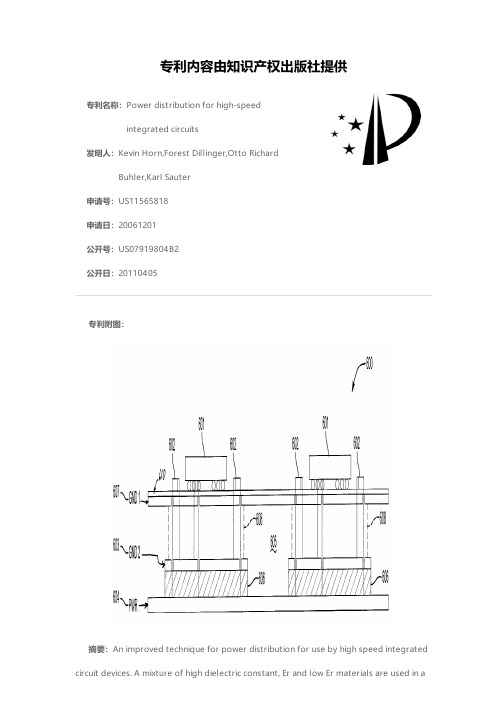
专利名称:Power distribution for high-speedintegrated circuits发明人:Kevin Horn,Forest Dillinger,Otto RichardBuhler,Karl Sauter申请号:US11565818申请日:20061201公开号:US07919804B2公开日:20110405专利内容由知识产权出版社提供专利附图:摘要:An improved technique for power distribution for use by high speed integrated circuit devices. A mixture of high dielectric constant, Er and low Er materials are used in adielectric layer sandwiched between the voltage and ground planes of a printed circuit board that is used to fixture one or more integrated circuit devices. The low Er material is used in an area contained by the location of the integrated circuit device and its corresponding decoupling capacitors located nearby. High Er material is used in areas between the regions of low Er material. The low Er material improves that speed at which current from an adjoining decoupling capacitor can propagate to a power pin of the integrated circuit device. The high Er material mitigates cross-coupling of noise between the low Er regions.申请人:Kevin Horn,Forest Dillinger,Otto Richard Buhler,Karl Sauter地址:Brighton CO US,Golden CO US,Boulder CO US,Pleasanton CA US国籍:US,US,US,US代理机构:Brooks Kushman P.C.更多信息请下载全文后查看。
The AVP 2000 / 3000 Encoder has been designed specifically to address the demands of today’s broad range of Contribution, DSNG, and Primary Distribution (C&D) applications delivering the most flexible solution in the market. Based on a compact 1RU form factor chassis with up to six hot swappable option slots with a single power supply unit (PSU), making it an ideal solution for the whole spectrum of high resilience to high density requirements. For applications demanding higher service resiliency then there is an option to have dual power supplies ensuring the unit delivers maximum performance, flexibility and reliability.A comprehensive range of processing options are available in the AVP Encoder including MPEG-4 AVC and HEVC which depending on the modules deployed enable operators to encode multiple formats as ASIand/or IP outputs. An integrated satellite modulator option offers high order DVB-S/S2/S2X modulation on both IF and L-Band outputs.Standard definition, high definition and ultra high definition in 4:2:0 and 4:2:2 modes are supported and for highest quality feeds the unit supports both 10-bit precision and p50/59.94 frame rates.A key aspect of the AVP is usability and it features a fully functional front panel to meet the demand of the contribution environment, including ease of operations, and quick menu access. In addition for those configuring the unit by PC a simplified user interface is available with all the commonly used controls on a single page. Overall the AVP offers broadcasters and network operators the most advanced video and audio compression technology available today and is key part of MediaKind’s C&D portfolio which also include receivers, and control and management software for scheduling.AVP 2000 / AVP 3000EncoderBase Unit Features• Six slot single PSU AVP2000/BAS/1AC/A • Four slot dual PSU AVP2000/BAS/2AC/A • Six slot dual PSU with Flying Leads AVP2000/BAS/2ACFL/ABase Chassis Functionality• Control via 2x electrical Ethernet (100/1000BaseT) • Data I/O via 4x electrical Ethernet (100/1000BaseT)with optional in-band control over Data I/O• License keys stored with option cards for maximumportability• Multiplexing and MPEG-2 Transport Stream generation • SMPTE 2022-1/-2 (Pro-MPEG) FEC on a single SPTS/MPTS • Encryption of output MPEG-2 Transport Stream usingBasic Interoperable Scrambling System (BISS) forsecure contribution links Supports BISS modes 0,1and E• SI table generation• Service level Remux (Requires AVP/HWO/ASI/IO/A)Platform Processing Capacities• Up to four CE-HEVC modules • Multiple concurrent I/O optionsBasic Modulation Value Pack 1• DVB-DSNG 8PSK and 16QAM modulation • DVB-S2 QPSK and 8PSK• Enable extended symbol rate range from 45 Msym/s to66 Msym/sAdvanced Modulation Value Pack 1• DVB-S2X MODCODs and FECs.• Higher order modulation support of DVB-S2 QPSK,8PSK, 16APSK, 32APSK and 64APSKProduct OverviewHigh Flexibility, Reliability and ServiceabilityThe AVP Encoder is the basis for the most efficient video compression engines available to the broadcast market. The platform itself is designed to address both the need for density with up to six option slots and the need for high resilience by making all the option slots hot swappable and the addition of a dual PSUversion of the chassis. A standard IP interface and a wide range of separate I/O options provide interfacing to multiple hybrid networks concurrently. This includes an integrated DVB-S and DVB-S2 satellite modulator providing high order modulation on IF and L-Bandoutputs. The AVP allows in-field serviceability, portability and system reconfiguration to address the widest range of C&D applicationsLeading High Quality CompressionThe AVP Encoder supports the CE-HEVC encodermodule providing support for HEVC and MPEG-4 AVC video compression. Each module can encode a single UHD (4k) video service or up to 4 HD video services. It supports 4:2:2 or 4:2:0, 8or 10-bit video, and can provide low and super low end to end latency encoding modes.So the AVP Encoder pushes encoding efficiency, serviceability and upgradeability to new levels of excellence.Efficient Use of SpectrumIt also supports DVB-S2 and DVB-S2X high ordermodulation on both IF and L-Band outputs. DVB-S2 gives a 30 % performance gain compared to DVB-S, and DVB-S2X gives up to 20% performance gain compared to DVB-S2.Front Panel OperationsA front panel provides complete unit control in mobile environments. Its unique ergonomic new design is the result of development based on industry feedback and includes:• Rotary control for fast selection and key-pad for easyvalue insertion• Quick access menus specifically designed for mobileoperations with customizable shortcuts and ample configuration storage• Audio metering1 Only available when the when theHardware OptionsCE-HEVC Series Encoder Modules(CE/HWO/CE-HEVC/BNC/A)(CE/HWO/HEVC/SFP/B)• Up to four modules per chassis depending on configuration• 4 x 3G/HD/SD-SDI, video input/BNC variant co-axial cable inputs/SFP variant has SFP slots• 1 UHD or 4 HD encodes per module2• HEVC and MPEG-4 AVC encoding capabilities2• 4:2:0 and 4:2:2 chroma sampling modes• 8 or 10-bit precision• 1 Mb/s to 100 Mb/s video bit-rate2• Multiple low latency modes• Up to 32 stereo pairs of audio encoding and pass-through2• VANC data extraction and support for generic VANC (SMPTE 2038)External Synchronisation Module(CE/HWO/EXTSYNC/A)• One slot per module. Up to one module per chassis • Supports synchronization of all encoders in the chassis to support single PCR operation• 10 MHz or HSYNC inputASI I/O Module(CE/HWO/ASI/IO/A)• One slot per module• 2 x ASI MPEG-2 Transport Stream outputs configuredas mirrored or independent (230Mbps max sharedbetween 2 outputs, 200Mbps max on any 1 output).• 2 x ASI inputs for Transport Stream pass-through toSatModG703 Module(CE/HWO/G703/A)• One slot per module• Supports E3 and DS3 output connectivityGPI Module(CE/HWO/GPI/A)• One slot per module• Supports GPO relay triggers for “Alarm” and “Failure”modes• Supports manual SCTE-35 splice point insertionSatellite Modulator(AVP/HWO/SATMOD/A)• SatMod card for DSNG2 Exact capabilities depend on module and Value Packs; pleaseSpecificationsTransport Stream InterfacingSatellite ModulatorManagement2x Electrical Ethernet (100/1000BaseT)SNMP v1/v2/v3, for alarm trapsUser management via web browserFully functional front panel controlSupport by nCompass Physical and PowerEnvironmental ConditionsCompliance。
MIC2033 Evaluation BoardHigh-Accuracy, High-Side, Fixed Current Limit Power SwitchMicrel Inc. • 2180 Fortune Drive • San Jose, CA 95131 • USA • tel +1 (408) 944-0800 • fax + 1 (408) 474-1000 •General DescriptionThe MIC2033 is a high-side MOSFET power distribution switch providing increased system reliability using 5% current limit accuracy.The MIC2033 has an operating input voltage range from 2.5V to 5.5V, is internally current limited, and has thermal shutdown to protect the device and system. The MIC2033 is offered with either active-high or active-low logic level enable input controls. It has an open drain fault status output flag with a built-in 32ms delay that asserts low during overcurrent or thermal shutdown conditions.The MIC2033 is available with several different fixed current limit options: 0.5A, 0.8A, 1A, and 1.2A. A capacitor-adjustable soft-start circuit minimizes inrush current in applications using high capacitive loads.The MIC2033 is offered in both 6-pin SOT-23 and 6-pin 2mm x 2mm thin DFN packages. It has an operating junction temperature range of −40°C to +125°C. RequirementsThe MIC2033 evaluation board requires a single power supply to provide V IN . The V IN power supply must be able to deliver a minimum of 2.5V and more than 1.5A capability. The output load can either be active or passive. PrecautionsThe evaluation board does not have reverse polarity protection. Applying a negative voltage to the V IN terminal can damage the device. In addition, the maximum V IN operating voltage of the MIC2033 evaluation board is 5.5V. Exceeding 5.5V on V IN can permanently damage the device.Getting Started1. Connect an external supply to the V IN terminal .Apply the desired input voltage to the V IN and ground terminals of the evaluation board, paying careful attention to polarity and supply voltage. The user can place an ammeter between the input supply and the V IN terminal to the evaluation board. Make sure that the supply voltage is monitored at the V IN terminal. The ammeter and/or power lead resistance can reduce the voltage supplied to the input.2. Connect the load to the V OUT and ground terminals.The load can be either passive (resistive) or active (as in an electronic load). The user can place an ammeter between the load and the V OUT terminal. Make sure that the output voltage is monitored at the V OUT terminal.3. Enable the switchThe MIC2033-12AYxx evaluation boards are configured for default enable using a 10k Ω pull-up resistor from the ENABLE pin to VIN. To disable the switch, place a jumper short across the jumper pins at TP2. The MIC2033-05BYxx evaluation boards are configured for default disable. To enable the switch, place a jumper short across the jumper pins at TP2. 4. Fault detectionThe MIC2033 is equipped with an error flag, FAULT/. TP3 is provided to monitor the FAULT/ pin.Ordering InformationPart Number DescriptionMIC2033-05BYM6 EV Evaluation board featuring the MIC2033-05BYM6 500mA Switch MIC2033-12AYM6 EV Evaluation board featuring the MIC2033-12AYM6 1.2A Switch MIC2033-05BYMT EV Evaluation board featuring the MIC2033-05BYMT 500mA Switch MIC2033-12AYMT EVEvaluation board featuring the MIC2033-12AYMT 1.2A SwitchApplication InformationSoft-StartSoft-start reduces the power supply input surge current at startup by controlling the output voltage rise time. The input surge appears while the output capacitor is charged up. A slower output rise time draws a lower input surge current.During soft-start, an internal current sink discharges the external capacitor at CSLEW to ground to control the ramp of the output voltage. The output voltage rise time depends on the value of C CSLEW, the input voltage, output voltage, and the current limit. Micrel recommends that the value of the CSLEW external capacitor be in the range of 0.1µF to 1µF. For the MIC2033 evaluation board, CSLEW = C3 = 0.1µF. Output VoltageThe MIC2033 evaluation board is available with either a 0.5A or 1.2A fixed current limit. If the output current exceeds the current limit, the MIC2033 switch enters constant current limit mode. The maximum allowable current limit can be less than the full specified and/or expected current if the MIC2033 is not mounted on a circuit board with sufficiently low thermal resistance. The MIC2033 responds to short circuits within 10µs to limit the output current. It also provides an output fault flag that asserts (low) for an overcurrent condition that lasts longer than the overcurrent fault response delay time (t FAULT/), which is typically 32ms.MIC2033-xxxYMx Evaluation Board SchematicsMIC2033-xxxYMT Evaluation BoardMIC2033-xxxYM6 Evaluation BoardBill of MaterialsNumber Manufacturer Description Qty. Item PartC1608X5R0J105K TDK(1)C1, C21.0µF/6.3V ceramic capacitor, X5R, 0603 206036D105KAT2A AVX(2)06033C104KAT2A TDK0.1µF/25V ceramic capacitor, X7R, 0603 1C3C1608X7R1E104K AVXR1, R2 CRCW060310K0FKEA Vishay/Dale(3) 10.0kΩ, film resistor, 0603, 1% 2U1 MIC2033-xxxYMx Micrel(4)High-accuracy, high-side, fixed current limit power switch 1Notes:1. TDK: .2. AVX: .3. Vishay: .4. Micrel, Inc.: .Evaluation Board PCB LayoutMIC2033-xxxYMT Evaluation Board – Top LayerMIC2033-xxxYMT Evaluation Board – Bottom LayerEvaluation Board PCB Layout (Continued)MIC2033-xxxYM6 Evaluation Board – Top LayerMIC2033-xxxYM6 Evaluation Board – Bottom Layer。
NCE N-Channel Enhancement Mode Power MOSFETDescriptionThe NCE40H12K uses advanced trench technology and design to provide excellent R DS(ON) with low gate charge. It can be used in a wide variety of applications.General Features● V DS =40V,I D =120AR DS(ON) <4.0m Ω @ V GS =10V R DS(ON) <7m Ω @ V GS =4.5V● High density cell design for ultra low Rdson ● Fully characterized avalanche voltage and current ● Good stability and uniformity with high E AS ● Excellent package for good heat dissipation ● Special process technology for high ESD capabilityApplication● Load switching● Hard switched and high frequency circuits ● Uninterruptible power supply100% UIS TESTED!100% ∆Vds TESTED!Schematic diagramMarking and pin assignmentTO-252-2L top viewPackage Marking and Ordering InformationDevice MarkingDeviceDevice PackageReel SizeTape widthQuantityNCE40H12K NCE40H12K TO-252-2L-- -Absolute Maximum Ratings (T C =25℃unless otherwise noted)Parameter Symbol Limit UnitDrain-Source Voltage V DS 40 V Gate-Source Voltage V GS ±20 V Drain Current-ContinuousI D 120 ADrain Current-Continuous(T C =100℃) I D (100℃) 85 A Pulsed Drain Current I DM 330 A Maximum Power Dissipation P D 120 W Derating factor0.8 W/℃Single pulse avalanche energy (Note 5)E AS 1080 mJOperating Junction and Storage Temperature RangeT J ,T STG-55 To 175℃Thermal CharacteristicThermal Resistance,Junction-to-Case (Note 2)R θJC1.25/W ℃Electrical Characteristics (T C =25℃unless otherwise noted)ParameterSymbolCondition Min Typ Max UnitOff CharacteristicsDrain-Source Breakdown Voltage BV DSS V GS =0V I D =250μA 40 45 - V Zero Gate Voltage Drain Current I DSS V DS =40V,V GS =0V -- 1 μA Gate-Body Leakage Current I GSS V GS =±20V,V DS =0V - - ±100 nA On Characteristics (Note 3) Gate Threshold VoltageV GS(th) V DS =V GS ,I D =250μA 1.2 1.8 2.5 V V GS =10V, I D =20A - 3.6 4.0Drain-Source On-State Resistance R DS(ON) V GS =4.5V, I D=10A - 5.8 7.0 m ΩForward Transconductance g FSV DS =10V,I D =20A 26 - - SDynamic Characteristics (Note4) Input Capacitance C lss - 5400 - PF Output CapacitanceC oss - 970 - PFReverse Transfer Capacitance C rssV DS =20V,V GS =0V,F=1.0MHz- 380 - PF Switching Characteristics (Note 4) Turn-on Delay Time t d(on) - 15 - nSTurn-on Rise Time t r - 18 - nS Turn-Off Delay Time t d(off) - 52 - nSTurn-Off Fall Time t fV DD =20V,I D =2A,R L =1Ω V GS =10V,R G =3Ω - 23 - nSTotal Gate Charge Q g - 75 nCGate-Source Charge Q gs - 10.5 nCGate-Drain ChargeQ gd V DS =20V,I D =20A,V GS =10V- 17 nC Drain-Source Diode Characteristics Diode Forward Voltage (Note 3) V SDV GS =0V,I S =40A -1.2 V Diode Forward Current (Note 2)I S - - 120 A Reverse Recovery Time t rr - 42 - nS Reverse Recovery Charge Qrr TJ = 25°C, IF = 40Adi/dt = 100A/μs (Note3)- 45 - nCForward Turn-On Timet onIntrinsic turn-on time is negligible (turn-on is dominated by LS+LD)Notes:1. Repetitive Rating: Pulse width limited by maximum junction temperature.2. Surface Mounted on FR4 Board, t ≤ 10 sec.3. Pulse Test: Pulse Width ≤ 300μs, Duty Cycle ≤ 2%.4. Guaranteed by design, not subject to production5. E AS condition : Tj=25℃,V DD =20V,V G =10V,L=1mH,Rg=25Ω,I AS =46.5ANCE40H12K Test circuit1) E AS Test Circuit2) Gate Charge Test Circuit3) Switch Time Test CircuitTypical Electrical and Thermal Characteristics (Curves)Vds Drain-Source Voltage (V)Figure 1 Output CharacteristicsVgs Gate-Source Voltage (V)Figure 2 Transfer CharacteristicsI D - Drain Current (A)Figure 3 Rdson- Drain CurrentT J -Junction Temperature(℃)Figure 4 Rdson-JunctionTemperatureQg Gate Charge (nC)Figure 5 Gate ChargeVsd Source-Drain Voltage (V)Figure 6 Source- Drain Diode ForwardR d s o n O n -R e s i s t a n c e (m Ω)I D - D r a i n C u r r e n t (A )I D - D r a i n C u r r e n t (A )N o r m a l i z e d O n -R e s i s t a n c eV g s G a t e -S o u r c e V o l t a g e (V )I s - R e v e r s e D r a i n C u r r e n t (A )Vds Drain-Source Voltage (V)Figure 7 Capacitance vs VdsVds Drain-Source Voltage (V)Figure 8 Safe Operation AreaT J -Junction Temperature (℃)Figure 9 Power De-ratingT J -Junction Temperature(℃)Figure 10 V GS(th) vs Junction TemperatureI D - D r a i n C u r r e n t (A )C C a p a c i t a n c e (p F )Square Wave Pluse Duration(sec)Figure 11 Normalized Maximum Transient Thermal Impedancer (t ),N o r m a l i z e d E f f e c t i v e T r a n s i e n t T h e r m a l I m p e d a n c eP o w e r D i s s i p a t i o n (W )TO-252 Package InformationDimensions In Millimeters Dimensions In Inches SymbolMin.Max.Min.Max.A 2.200 2.400 0.087 0.094A1 0.000 0.127 0.000 0.005b 0.660 0.860 0.026 0.034c 0.460 0.580 0.018 0.023D 6.500 6.700 0.256 0.264D1 5.100 5.460 0.201 0.215 D2 4.830 TYP. 0.190 TYP.E 6.000 6.200 0.236 0.244e 2.186 2.386 0.086 0.0940.386 0.409L 9.80010.400L1 2.900 TYP. 0.114 TYP.L2 1.400 1.700 0.055 0.067 L3 1.600 TYP. 0.063 TYP.L4 0.600 1.000 0.024 0.039 Φ 1.100 1.300 0.043 0.051 θ0°8°0°8°h 0.000 0.300 0.000 0.012V 5.350 TYP. 0.211 TYP.Attention:■Any and all NCE power products described or contained herein do not have specifications that can handle applications that require extremely high levels of reliability, such as life-support systems, aircraft's control systems, or other applications whose failure can be reasonably expected to result in serious physical and/or material damage. Consult with your NCE power representative nearest you before using any NCE power products described or contained herein in such applications.■ NCE power assumes no responsibility for equipment failures that result from using products at values that exceed, even momentarily, rated values (such as maximum ratings, operating condition ranges, or other parameters) listed in products specifications of any and all NCE power products described or contained herein.■Specifications of any and all NCE power products described or contained herein stipulate the performance, characteristics, and functions of the described products in the independent state, and are not guarantees of the performance, characteristics, and functions of the described products as mounted in the customer’s products or equipment. To verify symptoms and states that cannot be evaluated in an independent device, the customer should always evaluate and test devices mounted in the customer’s products or equipment.■ NCE power Semiconductor CO.,LTD. strives to supply high-quality high-reliability products. However, any and all semiconductor products fail with some probability. It is possible that these probabilistic failures could give rise to accidents or events that could endanger human lives, that could give rise to smoke or fire, or that could cause damage to other property. When designing equipment, adopt safety measures so that these kinds of accidents or events cannot occur. Such measures include but are not limited to protective circuits and error prevention circuits for safe design, redundant design, and structural design.■ In the event that any or all NCE power products(including technical data, services) described or contained herein are controlled under any of applicable local export control laws and regulations, such products must not be exported without obtaining the export license from the authorities concerned in accordance with the above law.■No part of this publication may be reproduced or transmitted in any form or by any means, electronic or mechanical, including photocopying and recording, or any information storage or retrieval system, or otherwise, without the prior written permission of NCE power Semiconductor CO.,LTD.■Information (including circuit diagrams and circuit parameters) herein is for example only ; it is not guaranteed for volume production. NCE power believes information herein is accurate and reliable, but no guarantees are made or implied regarding its use or any infringements of intellectual property rights or other rights of third parties.■ Any and all information described or contained herein are subject to change without notice due to product/technology improvement, etc. When designing equipment, refer to the "Delivery Specification" for the NCE power product that you intend to use.■This catalog provides information as of Sep.2010. Specifications and information herein are subject to change without notice.。
BUILDINGELECTRICITYAbstract:In view of the particularity andproject characteristics of super high⁃rise buildings,this paper introduces the design idea of power supplyand distribution system of Suzhou China⁃SingaporeTower,including medium⁃voltage power supply anddistribution system,low⁃voltage power distributionsystem,power distribution system of air defensebasement,electric energy saving,etc.,realizing thepurpose of green energy saving under the premise ofensuring safety and reliability.Key words:super high⁃rise building;powersupply and distribution system;load classification;power supply scheme;diesel generator set;airdefense basement;protective unit;energy saving摘要:针对超高层建筑的特殊性及项目特点,介绍苏州中新大厦供配电系统的设计思路,包括中压供配电系统、低压配电系统、防空地下室配电系统、电气节能等,在确保安全可靠的前提下,实现绿色节能的目的。
关键词:超高层建筑;供配电系统;负荷分级;供电方案;柴油发电机组;防空地下室;防护单元;节能中图分类号:TU852文献标识码:Adoi:10.3969/j.issn.1003-8493.2019.10.0020引言苏州中新大厦位于中国-新加坡苏州工业园区独墅湖畔,是继东方之门、苏州中心之后园区又一地标性建筑。
Power distribution d esign for high-rise building fire [Abstract] This paper analyzes China's current power supply and distribution of tall buildings in several fire design, combined with specification and engineering examples for the distribution of the current high-rise building design to explore the problems and propose appropriate solutions.[Key words] high-rise building fire Supply Emergency Power Supply Power Supply As China's national economic development, building more and more land, more and more precious land resources, prompting the development of various types of construction to the high-level, so high-rise building fire safety is increasingly a cause-oriented. For the characteristics of high-rise building fires, high-rise building fire safety design should be based on self-defense self-help, while the fire service for the distribution is to ensure the normal operation of the key fire-fighting facilities, directly related to high-rise building fire safety. Therefore, this article from the fire power configuration, fire distribution, fire electrical wiring for high-rise building power supply and distribution reliability analysis, propose appropriate solutions to ensure high-rise building fire safety standards.1. High-rise building fire power scheme1.1 specification power supply requirements for fireAccording to "fire protection design of tall buildings" (hereinafter referred to as "high regulation") provides high-rise building fire power should be the current national standard "for power distribution system design specifications," the requirements of the design, a class of construction by a load of required power supply, second-class high-rise buildings should be two power load requirements. According to "civil electrical specifications" (JGJ/T16-92) provides a load consists of two power supply, when a power failure, the other at the same time the power outage Buzhi Yu; a load is especially important in load, in addition to the above-mentioned two power supplies, theMust also be an additional emergency power supply of the third power; 2 load power should make sure that when the power transformer failure or circuit common failure, without interruption of power supply (or the rapid recovery after the interruption), the load is relatively small or regional power supply The difficult conditions, the two loads can be more than a return to 6KV dedicated overhead power lines or cables.1.2 The composition of high-rise building fire powerFire power is to ensure that high-rise building and fire normally fire-fighting equipment under normal electricity supply. Generally considered the main power supply and pose a fire emergency power supply. When the main power failure, emergency power supply can continue to supply to the fire-fighting equipment. Commonly used in emergency power supply are: (1) independent of the normal power-generating units (2) power supply network, independent of the normal power supply dedicated feeder circuit. (3) battery; (4) dry batteries.1.3 common Fire Power1.3.1 Dual Power high-voltage single-supply bus is not sub -Dual power high-voltage power supply section is not a single bus, two-loop high-voltage power supply at the same time, prepare a normal one to use, in this way to reduce contact between cabinets and a voltage transformer cabinet, saving infrastructure investment, reducing the high voltage distribution Electric room building area is beneficial to both, this approach requires two-way are guaranteed 100% of the load of electricity, when the cleaning bus or bus failure will cause all the power outages, poor reliability of their electricity supply is generally not used in high-rise construction.1.3.2 Dual Power high-voltage single-supply busbar sectionDual power supply high-pressure single-busbar sub-way, two-loop high-voltage power supply at the same time, each other back. High reliability of this approach, particularly for electrical equipment, fire two power requirements at the last and easy to implement the provisions of a switch, which is relatively common wiring.1.3.3 3 power supply high-pressure single-bus sub -Three sub-power high-voltage single power supply bus, three-loop high-voltage powersupply, the normal dual-use when a preparation, this approach has a high reliability, suitable for a larger load capacity of the important users.1.3.4 a main high voltage power supply, 380V power supply for the city, emergency power supply networkSmaller building, was not by the consumption, the local access to two power supplies and difficult, in the vicinity have 380V power supply when the main power supply can be used a high-voltage power supply, 380V power supply for emergency power supply. If the economy can also be allowed if the use of diesel generator sets for emergency power supply.1.4 plus the idea of diesel-powered generator setsAt present high-rise buildings, international and domestic universal power supply is based on the dual-power supply was equipped with a diesel generator as an emergency power supply, which is especially important to meet a load of power supply load requirements (Figure 1 does not include the dotted line part of the ). However, dual power plus the power supply of diesel generating sets in most parts of northern China are still subject to weather conditions. As a long time in the north in winter, the temperature low. As an emergency power supply diesel generator sets at low temperatures is difficult to immediately start power supply, and some even two or three minutes can not start.The dual power supply in most parts of 10KV substation quoted from the same strict sense, its essence is a power failure when the substation, the two power supplies also failed, causing power supply system completely paralyzed. In fire cases, this will expand the fire, causing serious losses is not allowed. Therefore, I envisage the dual power on diesel generator sets based on the season, plus a power supply, G 柴油发电机组季节电源图1 三电源加柴油发电机组供电方式and enable it to their own independent power supply.In the case of low winter temperatures, reducing the reliability of diesel generators, we will connect the power this season, for increasing theElectric system reliability. When the temperatures rise, we stopped the season to the power supply department reported that power supply, you can save running costs. And this season there are three power options: First, quoted all the way from the substation 10KV high voltage power supply as the season (Figure 1), the advantage of high reliability power supply, the shortfall is that the higher investment in infrastructure; second is from a nearby high-rise buildings along 10KV transformer high-voltage end of the quoted or cited all the way low end of the season as a 380/220V power supply; third all the way from the city network cited as the season 380/200V power supply.1.5 Building Configuration Thinking of diesel generator sets"High regulation" fire-fighting equipment supply should be provided "for the power distribution system design specifications" GB50052-95 requirements of the design, and the specification of a load is especially important in load did not involve the fire load in their fire power as long as there two power supplies can meet the requirements of "high regulation" also requires a class of high-rise building fire load electricity requirements should be a power supply, and a distribution box office in the final automatic switching device to ensure that fire safety facilities in When the fire power and reliable, able to function properly. In the "high regulation" is not clearly defined one, second-class high-rise buildings need to configure the diesel generators.Thus in recent years, newly emerging high-rise building fire load does not require allocating additional diesel generators. However, the specific power supply design, the vast majority of high-rise buildings from the electricity grid connection of two-way line of 10KV power into electricity, which can not meet the specifications where two power supply requirements. System blackout caused either by an internal fault, some caused by power failures, as a regional power grid in the main grid voltage of the upper part is a grid, so the user either from electric power lineto take a few back into the line also can not be in the strict sense of the two an independent power supply, power grid failures can cause a variety of all the power into the line at the same time a result of loss of power supplyBlackout. In fact, the Road 10KV high voltage power supply taken from a different substation is very difficult, and diesel generating sets to configure a small investment, the use of good results and will comply with regulatory requirements, so the design of high-rise building shall be fitted with diesel-powered generator sets. I think that explicit requirements specification which can be high-rise buildings should be equipped with diesel generators.2. High-rise building fire distribution2.1 common Fire Distribution ProgramFire distribution methods are commonly used in radiation type, tree type, chain, four kinds of hybrid(1) The radial distribution of the failure of any one line to each other affect each other, the equipment is easy to manage a high supply reliability. However, more than qualifying non-ferrous metals consumed in large quantities, switching equipment, and more investment in higher operating costs for a single piece of equipment of large capacity, power supply reliability high. (Figure 2 a)(2) The trunk-type distribution when the route failure, a larger sphere of influence, but coupled with alternate routes and to achieve switching to improve power supply reliability for a more uniform distribution of places. (Figure 2 b)(3) chain and the trunk-type is basically the same, but the low-reliability than the trunk, when the middle of a piece of equipment failures associated equipment in the back will lose power. (Figure 2 c)()放射式树干式()链式()混合式图2 常用配电方式(4) Mixed type, including two kinds of radiation type and tree-type distribution method is the victory of more high-rise building in a ligand distribution method. (Figure 2 d)2.2 The current issue of widespread distribution(1) of the fire electrical equipment such as fire control room, fire pump fire power instead of using a dedicated power supply, while the use of general load on the socket for the power lines, so that in case of fire in the building off the main power supply After the fire power the device's power also will be without electricity and fire-fighting equipment paralyzed, its fire immeasurable loss.(2) Some spare each other, such as fire pumps, fire fighting equipment at the end of the focus on two power each vote, there is no use of the equipment are radiation from the fire power supply power distribution room, but from the power distribution room leads to a main line, in the Preparation of the end of each parallel equipment. The result is that once the main line causing the problem (and the main line caused a great chance of failure) in each stand to lose power devices are unable to start, without achieving the desired results.(3) sharing power distribution equipment, fire linkage, there is no requirement of the end of the distribution box is located two-way automatic switching devices, or automatic switching devices of poor quality, low reliability. In the fire case,the standby power can not automatically switch to emergency power supply, power supply interruption. Some use the manual switch, when the firefighters reached the scene and then look for the power switching devices to switch, which will delay aircraft, resulting in heavy losses.2.3 The solution to the problem(1) Normal working power supply and emergency power supply shall be self-made system, independent distribution. When the power supply and lighting separately, then the power and lighting should be available to work the power distribution system and emergency power distribution system. Ensure that a class load of fire, electricity and other conditions in the fire, by the emergency power supply a continuous power supply, second-class load to ensure two-loop switching power supply.(2) In the fire power distribution design and installation of electricity, the power consumption of the large or a higher concentration of fire power equipment, such as fire control room, fire pumps, power distribution room should be the introduction of radial supply, and to ensure that the main equipment and standby equipment, power lines independent of each other.(3) Fire system equipment, power distribution share should be in the most power distribution boxes located at the end of two-way automatic switching device, and install high-quality power supply automatic switching devices. If you are installing a manual switching device, it is desirable that the equipment room distribution box. So that in case of emergency fire personnel can be easy to find and achieve in a short time to switch.3. Guanfang Hotel Fire Design and Analysis of Power Supply and Distribution3.1 Basic InformationGuanfang Hotel is located in Lijiang City, Snow Mountain Road, basement, ground floor 21, is a five-star hotel, belongs to a class of tall buildings. 10kv high voltage power supply to its dual-supply single-bus sub-power supply, auto-switching. Normal working hours, while two-way power supply, each other back and each shoulder 50% of the load. Power failure the way, another way for the full load power. No dieselgenerator sets. Route high-pressure system and low-voltage power distribution systems approach basically uses radiology systems, floor distribution system is a composite style, power distribution wiring the main trunk with Caine wells.Set up their fire power devices are used end of the dual power automatic switch device.3.2 Reliability Analysis of Power Supply and DistributionAccording to the "high regulation" in requiring the construction of tall buildings is a class, according to "civil construction for the distribution design standards" should be equipped with two power supplies to power. In the actual design and construction which uses a dual-supply single-busbar sub-10kv power supply, the fire control room, fire and other fire-fighting equipment lift the power supply distribution box office at the last one set up automatic switching device. Seems to meet the specification requirements, but the two power substations with the quote from Xiangshan, its essence is a grid of two loops, rather than two separate power supplies. When the substation failure on the entire power supply system is paralyzed. The Lijiang city alone, within a substation, from another independent quoted a power substation is very difficult, plus Lijiang Xiangshan substation is Daito hydropower electricity, hydroelectric power supply by the seasonal impact of the dry season, a power generation a small amount of the allocation of power followed by scoring city, stopped a battery compartment for a time. This will significantly affect the building power supply system reliability.At the same time as two-way 10kv power supply, spare each other, according to the capacity of transformers included in the regular standby fire pumps, spray pumps and other fire-fighting facilities to choose the load, while the building's fire load of about 900kw, non-fire load of about To 3000kw, its infrastructure investment in high operating cost more. This is just one company rather than a compliant design of the economy.In the power supply system installed in an automatic removal of loading device, when the system automatically removed when the fire with the fire of non-electrical equipment, transformer fire on a bus load of electrical equipment to prevent thespread of fire and fire electric shock accident occurred.The building is divided into 8 by function power partitions, each partition also on the electrical load level, the function of each layer according to power, lighting, two separate power distribution systems. The fire district for each power supply are two power supply electrical equipment, and a distribution box office at the last auto-switching, so that the design complied with the specifications, in the case of fire, firefighters in time understand the fire parts of the site-specific, accurate and starting the fire pump, sprinkler pump and other fire-fighting facilities, the timely removal of parts of the fire power.3.3 The improved design of the programWas equipped with an auto-start diesel generators as an emergency power supply. The two parts to the fire-fighting equipment from the power supply, the first part is from the mains supply, the second part of the power supply from diesel generators, and the last one automatically switch distribution box office. When the main power fails, by diesel-powered generator sets to the entire building. As the working electric power supply and power backup power, diesel generators only power supply and backup power at work when no electric starter. This will greatly enhance the power supply system reliability.Two-way 10kv power supply can be designed into the way to work all the way back. Power Supply by line consideration, according to the work of standby power after the power failure to maintain the main building elevator, room lighting load calculation. When a fire removal of non-fire power, auto-connected to fire pumps, sprinkler pump and other fire-fighting facilities. This will reduce the transformer capacity, was equipped with diesel generator set up for supply reliability. Such infrastructure investment, high economic efficiency.In various fire-fighting equipment of the power supply on the power distribution according to the respective features, fire pumps, spray pumps, fire lifts, fire control room, smoke fans, etc. due to large capacity, high reliability requirements, can be designed dual power supply, radial distribution, and at the end automatic switching; fire, emergency lighting, fire linkage control equipment, fire alarmcontroller, etc. are widely distributed, and distributed evenly, can be designed dual power supply, tree-type distribution.4. High-rise building fire safety equipment, electrical wiring4.1 specification for electrical equipment, fire safety requirements of power distribution linesAccording to the "high regulation" provides that the fire distribution lines shall meet the following requirements:(1) When using dark laying should be laid without burning body structure, and the protective layer thickness of not less than 30mm.(2) When using the laying out, they should use metal pipe or metal trunking painted fire-resistant coating to protect.(3) When the use of insulation and sheath extension for non-fuel materials, cables, may from time to wear a metal pipe protection, but it should be laid in cable wells.4.2 Common Fire wiring methods4.2.1 Protection of fire-resistant coatingExterior painted in an ordinary fire retardant coating to protect cables, the most commonly used fire coatings, such as T60-1 decorative fireproof coatings.4.2.2 PVC protection for surfaceWear of metal pipe or PVC plastic pipe out deposited in the wall, the outer wall of fire-resistant coating to protect brushing.4.2.3 PVC protection, ConcealedWear of metal pipe or PVC plastic pipe is located in the dark without burning body structures.4.2.4 use of fire-resistant, fire-retardant insulationWire insulation layer or jacket with a high oxygen index (usually "30) of flame-retardant material or the use of a non-combustible inorganic materials as fire-resistant type insulation.4.3 high-rise building fire electrical wiring problems and solutions4.3.1 Electrical circuit conductor selection based on the lack of securityAs the current "high regulation" on the fire limits of distribution lines and timelimits of high-temperature requirements are not clearly defined, which led to the construction unit will be an opportunity, in order to get some small interest, we chose to buy ordinary wires, the fire performance greatly reduced , and even to buy counterfeit goods for wiring installation.4.3.2 Electrical wiring while ignoring its fire-resistant coating is validThe most common wiring is painted fire-resistant coating fire protection, fire-resistant coating, but the general validity of short, often a few years will lose fire resistance. The related specifications are not provided in this regard, therefore, whether merchants or functional departments are not taken seriously enough, over the past few years, virtually on its fire risk increases.4.3.3 Electrical wiring systems use products do not meet the requirements. Designers according to design specifications is generally selection. The problem is a small number of fake and shoddy products, either on the wire itself or circuit switching equipment, are lower than the national standard, in practice there is a systematic operation of fire danger.From the above analysis of the problems, mainly because the relevant provisions of the specification is inadequate. Therefore, specifications should clearly define the limits of the fire wiring for high-temperature and time limit put forward corresponding measures. For in terms of investment in construction businesses, the entire investment in wiring the fire relative to total investment is minimal, but the incident caused the loss of wiring is immeasurable, so the configuration should be of high quality wire & cable, and lines to carry out regular maintenance maintenance.第11 页共11 页。