HD74AC123AP中文资料
- 格式:pdf
- 大小:248.65 KB
- 文档页数:7

74ls123中文资料汇总(74ls123引脚图及功能74ls123推荐工作条件74ls123静态特性【1】:测试条件中的“最大”和“最小”用推荐工作条件中的相应值。
【2】:若在Q测VOH,/Q测VOL,Q测IOS时:'123 的Cext 接地;LS123 的Rext/Cext接地,B和CLR接VIH,A接 2V到 0V的脉冲电压。
若在/Q 测 VOH、Q 测 VOL、/Q 测 IOS 时:'123 的 Cext 开路【3】:测'123 时:Cext=0.02μF,Rext=25kΩ。
静态:所有A 和 CLR 接 2.4V,所有 B 接地。
触发态:所有 B 和 CLR 接 2.4V,所有 B 接地。
测'LS123 时:所有 A、B、CLR 接 4.5V,时钟瞬时接地后接 4.5V。
74ls123动态特性【4】:tPLH-输出由低到高电平传输延迟时间tPHL-输出由高到低电平传输延迟时间tWQ-Q端输出脉冲宽度三款74ls123应用电路及原理应用电路一:振铃检测、模拟摘机电路如图2,振铃检测电路是由光耦TLP521-1和74LS123构成。
当有电话呼入时,电话线上传输的25HZ、90V 的交流振铃信号由C1、C2隔离直流后由整流桥整流,整流后的直流电压值较高,经光电隔离器U1后输出TTL脉冲信号,该脉冲经74LS123整形成大方波信号,该方波信号送至单片机的P3.5引脚进行计数,当计数值达到预设值时,单片机P1.0引脚输出高电平,三极管Q1导通则继电器K1动作,将负载电阻R5(330Ω)接入电路实现模拟摘机。
这里所说的模拟摘机是指将R5接入电路后,电话线上就会出现大于10mA的电流,交换中心检测到这一电流后就不再输出振铃信号而是转为接通电话。
人们手动摘机接通电话时的工作过程与此一致,因此称为模拟摘机。
如果振铃信号没有达到预设值就消失,则单片机的计数值清零,控制器不动作。

HD74AC165/HD74ACT165Parallel-Load 8-bit Shift RegisterADE-205-374 (Z)1st. EditionSep. 2000 DescriptionThis 8-bit serial shift register shifts data from QA to QHwhen clocked, Parallel inputs to each stage areenabled by a low level at the Shift/Load Input. Also included is a gated clock input and a complementary output from the eighth bit.Clocking is accomplished through a 2-input NOR gate permitting one input to be used as a clock inhibit function. Holding either of the clock inputs high inhibits clocking, and holding either clock input low with the Shift/Load input high enables the other clock input. Data transfer occurs on the positive going edge of the clock. Parallel loading is inhibited as long as the Shift/Load input is high. When taken low, data at the parallel inputs is loaded directly into the register independent of the state of the clock.Features• Outputs Source/Sink 24 mA• HD74ACT165 has TTL-Compatible InputsHD74AC165/HD74ACT1652Pin ArrangementLogic SymbolPin NamesA to H Parallel Inputs S I Serial Input CP Clock Input S LShift Load Clock Inhibit Clock Inhibit Q H , Q HOutputsHD74AC165/HD74ACT1653Truth TableInputsClockParallel Internal Outputs Outputs S L Inhibit CP S I A ······ H Q A Q B Q H L X X X a ······ h a b h H L LX X Q A D Q B O Q HO HL H X H Q An Q Gn HL L X L Q An Q Cn H HXXXQ A DQ B OQ HOH :High Voltage Level L :Low Voltage Level X :Immaterial: Low-to-High Clock TransitionHD74AC165/HD74ACT1654Logic DiagramDC Characteristics (unless otherwise specified)ItemSymbol Max Unit ConditionMaximum quiescent supply current I CC 80µA V IN = V CC or ground, V CC = 5.5 V,Ta = Worst caseMaximum quiescent supply current I CC 8.0µA V IN = V CC or ground, V CC = 5.5 V,Ta = 25°CMaximum additional I CC /input (HD74ACT165)I CCT1.5mAV IN = V CC – 2.1 V, V CC = 5.5 V,Ta = Worst caseHD74AC165/HD74ACT1655AC Characteristics: HD74AC165Ta = +25°C C L = 50 pFTa = –40°C to +85°C C L = 50 pF ItemSymbol V CC (V)*1Min Typ Max Min Max Unit Maximum count f max3.385——70—MHzfrequency 5.0100——90—Propagation delay t PLH 3.3 1.011.017.5 1.020.5ns CP to Q H or Q H 5.0 1.08.011.5 1.013.5Propagation delay t PHL 3.3 1.012.018.0 1.021.5ns CP to Q H or Q H 5.0 1.08.512.5 1.014.5Propagation delay t PLH 3.3 1.013.519.5 1.022.5ns H to Q H or Q H 5.0 1.09.513.5 1.015.5Propagation delay t PHL 3.3 1.09.014.0 1.016.5ns H to Q H or Q H 5.0 1.0 6.59.5 1.011.0Propagation delay t PLH 3.3 1.011.520.5 1.023.5ns S L to Q H or Q H 5.0 1.08.514.0 1.016.0Propagation delay t PHL 3.3 1.010.016.5 1.019.5ns S L to Q H or Q H 5.01.07.511.01.012.5Note:1.Voltage Range 3.3 is 3.3 V ± 0.3 VVoltage Range 5.0 is 5.0 V ± 0.5 VHD74AC165/HD74ACT1656AC Operating Requirements: HD74AC165Ta = +25°C C L = 50 pFTa = –40°C to +85°C C L = 50 pFItemSymbol V CC (V)*1Typ Guaranteed MinimumUnit Setup time, HIGH or LOW t su3.3 3.5 5.0 6.0nsH to S L5.0 2.5 4.0 4.5Hold time, HIGH or LOW t h3.3–1.00.50.5ns H to S L5.0–0.50.50.5Setup time, HIGH or LOW t su 3.3 1.0 3.5 4.0ns S in to CP5.00.5 3.0 3.5Hold time, HIGH or LOW t h 3.3 1.5 2.0 2.0ns S in to CP5.0 1.0 2.0 2.0Setup time, HIGH or LOW t su 3.3 3.0 5.06.0ns S L to CP5.0 2.0 4.0 4.5Hold time, HIGH or LOW t h 3.3–2.00.00.0ns S L to CP5.0–1.00.00.0Recovery time clock inhibit t rec 3.3 2.5 3.5 3.5ns to CP5.0 2.0 3.0 3.0Clock pulse width t w 3.3 3.0 5.57.0ns 5.03.04.55.0Note:1.Voltage Range 3.3 is 3.3 V ± 0.3 VVoltage Range 5.0 is 5.0 V ± 0.5 VHD74AC165/HD74ACT1657AC Characteristics: HD74ACT165Ta = +25°C C L = 50 pFTa = –40°C to +85°C C L = 50 pF ItemSymbol V CC (V)*1Min Typ Max Min Max Unit Maximum count frequency f max 5.070——60—MHz Propagation delay CP to Q H or Q H t PLH 5.0 1.08.513.5 1.015.5ns Propagation delay CP to Q H or Q H t PHL 5.0 1.09.514.0 1.016.5ns Propagation delay H to Q H or Q H t PLH 5.0 1.010.513.5 1.015.5ns Propagation delay H to Q H or Q H t PHL 5.0 1.07.511.0 1.012.5ns Propagation delay S L to Q H or Q H t PLH 5.0 1.09.515.0 1.018.0ns Propagation delay S L to Q H or Q H t PHL5.01.08.513.01.015.5nsNote:1.Voltage Range 5.0 is 5.0 V ± 0.5 VHD74AC165/HD74ACT1658AC Operating Requirements: HD74ACT165Ta = +25°C C L = 50 pFTa = –40°C to +85°C C L = 50 pFItemSymbol V CC (V)*1Typ Guaranteed MinimumUnit Setup time, HIGH or LOW H to S Lt su 5.0 3.0 4.0 4.5ns Hold time, HIGH or LOW H to S Lt h 5.0–1.00.00.0ns Setup time, HIGH or LOW S in to CPt su 5.00.5 3.0 3.5ns Hold time, HIGH or LOW S in to CPt h 5.00.5 2.0 2.0ns Setup time, HIGH or LOW S L to CPt su 5.0 2.0 4.0 4.5ns Hold time, HIGH or LOW S L to CPt h 5.0–1.50.00.0ns Recovery time clock inhibit to CPt rec 5.0 2.0 3.0 3.0ns Clock pulse width t w5.03.57.08.0nsNote:1.Voltage Range 5.0 is 5.0 V ± 0.5 VCapacitanceItemSymbol Typ Unit Condition Input capacitanceC IN 4.5pF V CC = 5.5 V Power dissipation capacitanceC PD50pFV CC = 5.0 VHD74AC165/HD74ACT165 Package Dimensions9HD74AC165/HD74ACT16510HD74AC165/HD74ACT16511Cautions 1.Hitachi neither warrants nor grants licenses of any rights of Hitachi’s or any third party’s patent,copyright, trademark, or other intellectual property rights for information contained in this document.Hitachi bears no responsibility for problems that may arise with third party’s rights, includingintellectual property rights, in connection with use of the information contained in this document.2.Products and product specifications may be subject to change without notice. Confirm that you havereceived the latest product standards or specifications before final design, purchase or use.3.Hitachi makes every attempt to ensure that its products are of high quality and reliability. However,contact Hitachi’s sales office before using the product in an application that demands especially high quality and reliability or where its failure or malfunction may directly threaten human life or cause risk of bodily injury, such as aerospace, aeronautics, nuclear power, combustion control, transportation,traffic, safety equipment or medical equipment for life support.4.Design your application so that the product is used within the ranges guaranteed by Hitachi particularlyfor maximum rating, operating supply voltage range, heat radiation characteristics, installationconditions and other characteristics. Hitachi bears no responsibility for failure or damage when used beyond the guaranteed ranges. Even within the guaranteed ranges, consider normally foreseeablefailure rates or failure modes in semiconductor devices and employ systemic measures such as fail-safes, so that the equipment incorporating Hitachi product does not cause bodily injury, fire or other consequential damage due to operation of the Hitachi product.5.This product is not designed to be radiation resistant.6.No one is permitted to reproduce or duplicate, in any form, the whole or part of this document withoutwritten approval from Hitachi.7.Contact Hitachi’s sales office for any questions regarding this document or Hitachi semiconductorproducts.Hitachi, Ltd.Semiconductor & Integrated Circuits.Nippon Bldg., 2-6-2, Ohte-machi, Chiyoda-ku, Tokyo 100-0004, Japan Tel: Tokyo (03) 3270-2111 Fax: (03) 3270-5109Copyright © Hitachi, Ltd., 2000. All rights reserved. Printed in Japan.Hitachi Asia Ltd.Hitachi Tower16 Collyer Quay #20-00,Singapore 049318Tel : <65>-538-6533/538-8577Fax : <65>-538-6933/538-3877URL : .sgURL NorthAmerica : /Europe : /hel/ecg Asia : Japan : http://www.hitachi.co.jp/Sicd/indx.htmHitachi Asia Ltd.(Taipei Branch Office)4/F, No. 167, Tun Hwa North Road,Hung-Kuo Building,Taipei (105), TaiwanTel : <886>-(2)-2718-3666Fax : <886>-(2)-2718-8180Telex : 23222 HAS-TPURL : Hitachi Asia (Hong Kong) Ltd. Group III (Electronic Components) 7/F., North Tower, World Finance Centre, Harbour City, Canton Road Tsim Sha Tsui, Kowloon, Hong Kong Tel : <852>-(2)-735-9218 Fax : <852>-(2)-730-0281 URL : Hitachi Europe Ltd.Electronic Components Group.Whitebrook Park Lower Cookham Road Maidenhead Berkshire SL6 8YA, United Kingdom Tel: <44> (1628) 585000Fax: <44> (1628) 585160Hitachi Europe GmbH Electronic Components Group Dornacher Stra βe 3D-85622 Feldkirchen, Munich Germany Tel: <49> (89) 9 9180-0Fax: <49> (89) 9 29 30 00Hitachi Semiconductor (America) Inc.179 East Tasman Drive,San Jose,CA 95134 Tel: <1> (408) 433-1990Fax: <1>(408) 433-0223For further information write to:Colophon 2.0。

HD74ALVCH16237316-bit Transparent D-type Latches with 3-state OutputsADE-205-179 (Z)Preliminary1st. EditionDecember 1996 DescriptionThe HD74ALVCH162373 is particularly suitable for implementing buffer registers, I/O ports, bidirectional bus drivers, and working registers. It can be used as two 8-bit latches or one 16-bit latch. When the latch enable (LE) input is high, the Q outputs follow the data (D) inputs. When LE is taken low, the Q outputs are latched at the levels set up at the D inputs. Active bus hold circuitry is provided to hold unused or floating data inputs at a valid logic level. All outputs, which are designed to sink up to 12 mA, include 26Ω resistors to reduce overshoot and undershoot.Features• V CC = 2.3 V to 3.6 V• Typical V OL ground bounce < 0.8 V (@V CC = 3.3 V, Ta = 25°C)• Typical V OH undershoot > 2.0 V (@V CC = 3.3 V, Ta = 25°C)• High output current ±12 mA (@V CC = 3.0 V)• Bus hold on data inputs eliminates the need for external pullup / pulldown resistors• All outputs have equivalent 26 Ω series resistors, so no external resistors are required.HD74ALVCH1623732Function TableInputs Output QOE LE D L H H H L H L L L L X Q 0 *1HXXZ H : High level L : Low level X : ImmaterialZ : High impedanceNote: 1.Output level before the indicated steady state input conditions were established.HD74ALVCH162373 Pin Arrangement3HD74ALVCH1623734Absolute Maximum RatingsItemSymbol Ratings Unit ConditionsSupply voltage V CC –0.5 to 4.6V Input voltage *1V I –0.5 to 4.6V Output voltage *1, 2V O –0.5 to V CC +0.5V Input clamp current I IK –50mA V I < 0Output clamp current I OK ±50mA V O < 0 or V O > V CC Continuous output current I O ±50mAV O = 0 to V CC ±100Maximum power dissipation at Ta = 55°C (in still air) *3P T 0.85W TSSOPStorage temperature Tstg–65 to 150°CNotes:Stresses beyond those listed under “absolute maximum ratings” may cause permanent damage to the device. These are stress ratings only, and functional operation of the device at these or any other conditions beyond those indicated under “recommended operating conditions” is not implied. Exposure to absolute maximum rated conditions for extended periods may affect device reliability.1.The input and output negative voltage ratings may be exceeded if the input and output clampcurrent ratings are observed.2.This value is limited to 4.6 V maximum.3.The maximum package power dissipation is calculated using a junction temperature of 150°Cand a board trace length of 750 mils.Recommended Operating ConditionsItemSymbol Min Max Unit ConditionsSupply voltage V CC 2.3 3.6V Input voltage V I 0V CC V Output voltageV O 0V CC V High level output currentI OH—–6mAV CC = 2.3 V —–8V CC = 2.7 V —–12V CC = 3.0 V Low level output currentI OL—6mA V CC = 2.3 V —8V CC = 2.7 V —12V CC = 3.0 V Input transition rise or fall rate ∆t / ∆v 010ns / V Operating temperatureTa–4085°C Note:Unused control inputs must be held high or low to prevent them from floating.HD74ALVCH162373 Logic Diagram5HD74ALVCH1623736Electrical Characteristics (Ta = –40 to 85°C)Item Symbol V CC (V) *1Min Max Unit Test Conditions Input voltageV IH 2.3 to 2.7 1.7—V2.7 to3.6 2.0—V IL2.3 to 2.7—0.72.7 to3.6—0.8Output voltageV OHMin to Max V CC –0.2—VI OH = –100 µA2.3 1.9—I OH = –4 mA, V IH = 1.7 V 2.3 1.7—I OH = –6 mA, V IH = 1.7 V3.0 2.4—I OH = –6 mA, V IH = 2.0 V 2.7 2.0—I OH = –8 mA, V IH = 2.0 V 3.02.0—I OH = –12 mA, V IH = 2.0 V V OLMin to Max —0.2I OL = 100 µA2.3—0.4I OL = 4 mA, V IL = 0.7 V 2.3—0.55I OL = 6 mA, V IL = 0.7 V3.0—0.55I OL = 6 mA, V IL = 0.8 V 2.7—0.6I OL = 8 mA, V IL = 0.8 V 3.0—0.8I OL = 12 mA, V IL = 0.8 V Input currentI IN 3.6—±5µA V IN = V CC or GND I IN (hold)2.345—V IN = 0.7 V 2.3–45—V IN = 1.7 V3.075—V IN = 0.8 V 3.0–75—V IN = 2.0 V 3.6—±500V IN = 0 to 3.6 V Off state output current *2I OZ 3.6—±10µA V OUT = V CC or GND Quiescent supply current I CC3.6—40µA V IN = V CC or GND∆I CC3.0 to 3.6—750µA V IN = one input at (V CC –0.6) V,other inputs at V CC or GND Notes: 1.For conditions shown as Min or Max, use the appropriate values under recommended operatingconditions.2.For I/O ports, the parameter I OZ includes the input leakage current.HD74ALVCH1623737Switching Characteristics (Ta = –40 to 85°C)ItemSymbol V CC (V)Min Typ Max Unit FROM (Input)TO(Output)Propagation delay timet PLH 2.5±0.2 1.0— 5.6nsDQt PHL2.7—— 5.03.3±0.3 1.1—4.22.5±0.2 1.0— 6.0LEQ2.7—— 5.33.3±0.31.0— 4.5Output enable timet ZH 2.5±0.2 1.0—7.0nsOEQt ZL2.7—— 6.43.3±0.3 1.0— 5.3Output disable timet HZ 2.5±0.2 1.9— 5.8nsOEQt LZ2.7—— 5.03.3±0.3 1.4—4.6Setup timet su2.5±0.2 1.0——ns 2.7 1.0——3.3±0.31.1——Hold timet h2.5±0.2 1.5——ns 2.7 1.7——3.3±0.31.4——Pulse widtht w2.5±0.23.3——ns 2.7 3.3——3.3±0.33.3——Input capacitance C IN 3.3— 3.0—pFControl inputs 3.3— 6.0—Data inputsOutput capacitanceC O3.3—7.0—pFHD74ALVCH1623738HD74ALVCH1623739HD74ALVCH16237310HD74ALVCH162373 Package DimensionsUnit : mm11Cautions1.Hitachi neither warrants nor grants licenses of any rights of Hitachi’s or any third party’s patent,copyright, trademark, or other intellectual property rights for information contained in this document.Hitachi bears no responsibility for problems that may arise with third party’s rights, includingintellectual property rights, in connection with use of the information contained in this document.2.Products and product specifications may be subject to change without notice. Confirm that you have received the latest product standards or specifications before final design, purchase or use.3.Hitachi makes every attempt to ensure that its products are of high quality and reliability. However,contact Hitachi’s sales office before using the product in an application that demands especially high quality and reliability or where its failure or malfunction may directly threaten human life or cause risk of bodily injury, such as aerospace, aeronautics, nuclear power, combustion control, transportation,traffic, safety equipment or medical equipment for life support.4.Design your application so that the product is used within the ranges guaranteed by Hitachi particularly for maximum rating, operating supply voltage range, heat radiation characteristics, installationconditions and other characteristics. Hitachi bears no responsibility for failure or damage when used beyond the guaranteed ranges. Even within the guaranteed ranges, consider normally foreseeable failure rates or failure modes in semiconductor devices and employ systemic measures such as fail-safes, so that the equipment incorporating Hitachi product does not cause bodily injury, fire or other consequential damage due to operation of the Hitachi product.5.This product is not designed to be radiation resistant.6.No one is permitted to reproduce or duplicate, in any form, the whole or part of this document without written approval from Hitachi.7.Contact Hitachi’s sales office for any questions regarding this document or Hitachi semiconductor products.Hitachi, Ltd.Semiconductor & Integrated Circuits.Nippon Bldg., 2-6-2, Ohte-machi, Chiyoda-ku, Tokyo 100-0004, Japan Tel: Tokyo (03) 3270-2111 Fax: (03) 3270-5109Copyright ' Hitachi, Ltd., 1999. All rights reserved. Printed in Japan.Hitachi Asia Pte. Ltd.16 Collyer Quay #20-00Hitachi TowerSingapore 049318Tel: 535-2100Fax: 535-1533URLNorthAmerica : http:/Europe : /hel/ecg Asia (Singapore): .sg/grp3/sicd/index.htm Asia (Taiwan): /E/Product/SICD_Frame.htm Asia (HongKong): /eng/bo/grp3/index.htm Japan : http://www.hitachi.co.jp/Sicd/indx.htmHitachi Asia Ltd.Taipei Branch Office3F, Hung Kuo Building. No.167, Tun-Hwa North Road, Taipei (105)Tel: <886> (2) 2718-3666Fax: <886> (2) 2718-8180Hitachi Asia (Hong Kong) Ltd.Group III (Electronic Components)7/F., North Tower, World Finance Centre,Harbour City, Canton Road, Tsim Sha Tsui,Kowloon, Hong Kong Tel: <852> (2) 735 9218Fax: <852> (2) 730 0281 Telex: 40815 HITEC HXHitachi Europe Ltd.Electronic Components Group.Whitebrook ParkLower Cookham Road MaidenheadBerkshire SL6 8YA, United Kingdom Tel: <44> (1628) 585000Fax: <44> (1628) 778322Hitachi Europe GmbHElectronic components Group Dornacher Stra§e 3D-85622 Feldkirchen, Munich GermanyTel: <49> (89) 9 9180-0Fax: <49> (89) 9 29 30 00Hitachi Semiconductor (America) Inc.179 East Tasman Drive,San Jose,CA 95134 Tel: <1> (408) 433-1990Fax: <1>(408) 433-0223For further information write to:。

Hitachi CodeJEDECEIAJWeight (reference value)DP-16 Conforms Conforms 1.07 gHitachi Code JEDEC EIAJWeight (reference value)FP-16DA —Conforms 0.24 g*Dimension including the plating thicknessBase material dimension° – 8°Hitachi CodeJEDECEIAJWeight (reference value)FP-16DNConformsConforms0.15 gUnit: mm*Dimension including the plating thickness Base material dimension° – 8°元器件交易网Cautions1.Hitachi neither warrants nor grants licenses of any rights of Hitachi’s or any third party’s patent,copyright, trademark, or other intellectual property rights for information contained in this document.Hitachi bears no responsibility for problems that may arise with third party’s rights, includingintellectual property rights, in connection with use of the information contained in this document.2.Products and product specifications may be subject to change without notice. Confirm that you have received the latest product standards or specifications before final design, purchase or use.3.Hitachi makes every attempt to ensure that its products are of high quality and reliability. However,contact Hitachi’s sales office before using the product in an application that demands especially high quality and reliability or where its failure or malfunction may directly threaten human life or cause risk of bodily injury, such as aerospace, aeronautics, nuclear power, combustion control, transportation,traffic, safety equipment or medical equipment for life support.4.Design your application so that the product is used within the ranges guaranteed by Hitachi particularly for maximum rating, operating supply voltage range, heat radiation characteristics, installationconditions and other characteristics. Hitachi bears no responsibility for failure or damage when used beyond the guaranteed ranges. Even within the guaranteed ranges, consider normally foreseeable failure rates or failure modes in semiconductor devices and employ systemic measures such as fail-safes, so that the equipment incorporating Hitachi product does not cause bodily injury, fire or other consequential damage due to operation of the Hitachi product.5.This product is not designed to be radiation resistant.6.No one is permitted to reproduce or duplicate, in any form, the whole or part of this document without written approval from Hitachi.7.Contact Hitachi’s sales office for any questions regarding this document or Hitachi semiconductor products.Hitachi, Ltd.Semiconductor & Integrated Circuits.Nippon Bldg., 2-6-2, Ohte-machi, Chiyoda-ku, Tokyo 100-0004, Japan Tel: Tokyo (03) 3270-2111 Fax: (03) 3270-5109Copyright ' Hitachi, Ltd., 1999. All rights reserved. Printed in Japan.Hitachi Asia Pte. Ltd.16 Collyer Quay #20-00Hitachi TowerSingapore 049318Tel: 535-2100Fax: 535-1533URLNorthAmerica : http:/Europe : /hel/ecg Asia (Singapore): .sg/grp3/sicd/index.htm Asia (Taiwan): /E/Product/SICD_Frame.htm Asia (HongKong): /eng/bo/grp3/index.htm Japan : http://www.hitachi.co.jp/Sicd/indx.htmHitachi Asia Ltd.Taipei Branch Office3F, Hung Kuo Building. No.167, Tun-Hwa North Road, Taipei (105)Tel: <886> (2) 2718-3666Fax: <886> (2) 2718-8180Hitachi Asia (Hong Kong) Ltd.Group III (Electronic Components)7/F., North Tower, World Finance Centre,Harbour City, Canton Road, Tsim Sha Tsui,Kowloon, Hong Kong Tel: <852> (2) 735 9218Fax: <852> (2) 730 0281 Telex: 40815 HITEC HXHitachi Europe Ltd.Electronic Components Group.Whitebrook ParkLower Cookham Road MaidenheadBerkshire SL6 8YA, United Kingdom Tel: <44> (1628) 585000Fax: <44> (1628) 778322Hitachi Europe GmbHElectronic components Group Dornacher Stra§e 3D-85622 Feldkirchen, Munich GermanyTel: <49> (89) 9 9180-0Fax: <49> (89) 9 29 30 00Hitachi Semiconductor (America) Inc.179 East Tasman Drive,San Jose,CA 95134 Tel: <1> (408) 433-1990Fax: <1>(408) 433-0223For further information write to:。

M54HC123/123A M74HC123/123AOctober 1993DUAL RETRIGGERABLE MONOSTABLE MULTIVIBRATORB1R(Plastic Package)ORDER CODES :M54HCXXXF1R M74HCXXXM1R M74HCXXXB1R M74HCXXXC1RF1R(Ceramic Package)M1R(Micro Package)C1R (Chip Carrier)PIN CONNECTIONS (top view)NC =No Internal Connecti o n.HIGH SPEEDt PD =25ns (TYP)at V CC =5V .LOW POWER DISSIPATIONSTANDBYSTATE I CC =4µA (MAX.)AT T A =25°C ACTIVE STATE I CC =200µA (TYP.)AT V CC =5V .HIGH NOISE IMMUNITYV NIH =V NIL =28%V CC (MIN.).OUTPUT DRIVE CAPABILITY 10LSTTL LOADS.SYMMETRICAL OUTPUT IMPEDANCE I OH =I OL =4mA (MIN.).BALANCED PROPAGATION DELAYS t PLH =t PHL.WIDE OPERATING VOLTAGE RANGE V CC (OPR)=2V TO 6V.WIDE OUTPUT PULSE WIDTH RANGE t WOUT =120ns ∼60s OVER AT V CC =4.5V .PIN AND FUNCTION COMPATIBLE WITH 54/74LS123The M54/74HC123is a high speed CMOS MONO-STABLE multivibrator fabricated with silicon gate C 2MOS technology.It achieves the high speed operation similar to equivalent LSTTL while main-taining the CMOS low power dissipation.There are two trigger inputs,A INPUT (negative edge)and 8INPUT (positive edge).These inputs are valid for slow rising/falling signals,(tr =tf =I sec).The device may also be triggered by using the CLR input (posi-tive-edge)because of the Schmitt-trigger input ;after triggering the output maintains the MONO-STABLE state for the time period determined by the external resistor Rx and capacitor Cx.When Cx ≥10nF and Rx ≥10K Ω,the output pulse width value is approssimatively given by the formula:t w(out)=K •Cx •Rx.Two different pulse width constant are available:K ≅0.45for HC123K ≅1for HC123A.Taking CLR low breaks this MONOSTABLE STATE.If the next trigger pulse occurs during the MONOSTABLEperiod it makes the MONOSTABLE period longer.Limit for values of Cx and Rx :Cx :NO LIMITRx :V CC <3.0V 5K Ωto 1M ΩV CC ≥3.0V 1K Ωto 1M ΩAll inputs are equipp ed with protection circuitsDESCRIPTION1/14M54/M74HC123/123A SYSTEM DIAGRAMTIMING CHART2/14BLOCK DIAGRAMNote:(1)Cx,Rx,Dx are external compo nents.(2)Dx is a clamping diode.The external capacitor is charged toV CC inthe stand-by state,i.e.no trigger.When the supply voltage is turned off Cx is discha rged mainly through an internal para sitic diode(see figures).If Cx is sufficiently large and V CC dec reases rapidy,there will be some pos sibility of da-maging the I.C.with a surg e current or latch-up.If the voltage sup ply filter capac itor is large eno ugh and V CC decrease slowly,the surg e current is automatically limited and damage the I.C.is avo ided.The maximum forward current of the parasitic diode is app roximately20 mA.In cases where Cx is large the time taken for the sup ply voltage to fall to0.4V CC canbe calculated as follows:t f≥(V CC–0.7)⋅Cx/20mAIn cases where t f is too short an external clamping diode is required to protect the I.C.from the surge current.FUNCTIONAL DESCRIPTIONSTAND-BY STATEThe external capacitor,Cx,is fully charged to V CC in the stand-by state.Hence,before triggering,tran-sistor Qp and Qn(connected to the Rx/Cx node)are both turned-off.The two comparators that control the timing and the two reference voltage sources stop operating.The total supply current is therefore only leakage current.TRIGGER OPERATIONTriggering occurs when:1st)A is”low”and B has a falling edge;2nd)B is”high”and A has a rising edge;3rd)A is low and B is high and C1has a rising edge. After the multivibrator has been retrigger ed com-parator C1and C2start operating and Qn is turned on.Cx then discharges through Qn.The voltage at the node R/C external falls.When it reaches V REFL the output of comparator C1 becomes low.This in turn resets the flip-flop and Qn is turned off.At this point C1stops functioning but C2continues to operate.The voltage at R/C external begins to rise with a time constant set by the external components Rx,Cx. Triggering the multivibrator causes Q to go high after internal delay due to the flip-flop and the gate.Q re-mains high until the voltage at R/C external rises again to V REFH.At this point C2output goes low and O goes low.C2stop operating.That means that after triggering when the voltage R/C external re-turns to V REFH the multivibrator has returned to its MONOSTABLE STATE.In the case where Rx⋅Cx are large enough and the discharge time of the ca-pacitor and the delay time in the I.C.can be ignored, the width of the output pulse tw(out)is as follows: t W(OUT)=0.46Cx⋅Rx(HC123)t W(OUT)=Cx⋅Rx(HC123A)M54/M74HC123/123A3/14FUNCTIONAL DESCRIPTION(continued)RE-TRIGGERED OPERATIONWhen a second trigger pulse follows the first its ef-fect will depend on the state of the multivibrator.If the capacitor Cx is being charged the voltage level of R/C external falls to Vrefl again and Q remains high i.e.the retrigger pulse arrives in a time shorter than the period Rx⋅Cx seconds,the capacitor charging time constant.If the second trigger pulse is very close to the initial trigger pulse it is ineffective ;i.e.the second trigger must arrive in the capacitor discharge cycle to be ineffective;Hence the mini-mum time for a second trigger to be effective de-pends on V CC and Cx.RESET OPERATIONCL is normally high.If CL is low,the trigger is not ef-fective because Q output goes low and trigger con-trol flip-flop is reset.Also transistor Op is turned on and Cx is charged quicky to V CC.This means if CL input goes low,the IC becomes waiting state both in operating and non operatin g state.TRUTH TABLEINPUTS OUTPUTSNOTEA B CL Q QH H OUTPUT ENABLEX L H L H INHIBITH X H L H INHIBITL H OUTPUT ENABLE L H OUTPUT ENABLE X X L L H INHIBITX:Don’t Care Z:High ImpedanceINPUT AND OUTPUT EQUIVALENT CIRCUITM54/M74HC123/123A4/14PIN DESCRIPTIONPIN No SYMBOL NAME AND FUNCTION 1,91A,2A Trigger Inputs(NegativeEdge Triggered) 2,101B,2B Trigger Inputs(PositiveEdge Triggered)3,111CLR,2CLR Direct Reset LOW and Trigger Action at Positive Edge4,121Q,2Q Outputs(Active LOW) 72R EXT/C EXT External ResistorCapacitor Connection 13,51Q,2Q Outputs(Active HIGH)14,61C EXT2C EXT External Capacitor Connection151R EXT/C EXT External ResistorCapacitor Connection8GND Ground(0V)16V CC Positive Supply VoltageIEC LOGIC SYMBOLABSOLUTE MAXIMUM RATINGSymbol Parameter Value Unit V CC Supply Voltage-0.5to+7V V I DC Input Voltage-0.5to V CC+0.5V V O DC Output Voltage-0.5to V CC+0.5VI IK DC Input Diode Current±20mAI OK DC Output Diode Current±20mAI O DC Output Source Sink Current Per Output Pin±25mAI CC or I GND DC V CC or Ground Current±50mAP D Power Dissipation500(*)mW T stg Storage Temperature-65to+150o C T L Lead Temperature(10sec)300o C Absolute Maximum Ratings are those values beyond whichdamage to the device may occu r.Functiona l ope ration und er these cond ition isnotimplied. (*)500mW:≅65o C derate to300mW by10mW/o C:65o C to85o CM54/M74HC123/123A5/14DC SPECIFICATIONSSymbolParameterTest ConditionsValueUnitV CC (V)T A =25oC 54HC and 74HC -40to 85o C 74HC -55to 125o C54HC Min.Typ.Max.Min.Max.Min.Max.V IHHigh Level Input Voltage 2.0 1.5 1.5 1.5V4.5 3.15 3.15 3.156.0 4.24.24.2V ILLow Level Input Voltage 2.00.50.50.5V4.5 1.35 1.35 1.356.0 1.81.81.8V OHHigh Level Output Voltage2.0V I =V IH orV IL I O =-20µA 1.9 2.0 1.9 1.9V4.5 4.4 4.5 4.4 4.46.05.96.0 5.9 5.94.5I O =-4.0mA4.18 4.31 4.13 4.106.0I O =-5.2mA 5.685.8 5.635.60V OLLow Level Output Voltage2.0V I =V IH orV IL I O =20µA 0.00.10.10.1V4.50.00.10.10.16.00.00.10.10.14.5I O =4.0mA 0.170.260.330.406.0I O =5.2mA 0.180.260.330.40I I Input Leakage Current6.0V I =V CC or GND ±0.1±1±1µA I I R/C Terminal Off State Current 6.0V I =V CC or GND ±0.1±1±1µA I CC Quiescent Supply Current6.0V I =V CC or GND 44080µA I CC ’Active StateSupply Current (1)2.0V I =V CC or GND Pin 7or 15V IN =V CC /245200260320µA 4.5500600780960µA 6.00.711.31.6mA(1):Per CircuitRECOMMENDED OPERATING CONDITIONSSymbol ParameterValue Unit V CC Supply Voltage 2to 6V V I Input Voltage 0to V CC V V O Output Voltage0to V CC VT op Operating Temperature:M54HC SeriesM74HC Series-55to +125-40to +85o C oC t r ,t fInput Rise and Fall Time0to 1000ns0to 5000to 400C X External Capacitor NO LIMITATIONpFR XExternal ResistorV CC <3V 5K to 1M ΩV CC ≥3V1K to 1M(*)The maximum allowable values of Cx and Rx are a function of leakage of capa citor Cx,the leakage of device and leakage due to the board layout and surface resistance.Susce ptibility to externally induced noise may occur for Rx >1M ΩM54/M74HC123/123A6/14AC ELECTRICAL CHARACTERISTICS(C L=50pF,Input t r=t f=6ns)Symbol ParameterTest Conditions ValueUnit V CC(V)T A=25o C54HC and74HC-40to85o C74HC-55to125o C54HCMin.Typ.Max.Min.Max.Min.Max.t TLH t THL Output TransitionTime2.0307595110ns4.581519226.07131619t PLH t PHL PropagationDelay Time(A,B-Q,Q)2.0102210265315ns4.5294253636.022364554t PLH t PHL PropagationDelay Time(C L RTR IGGE R-Q,Q)2.0102235295355ns4.5314759716.023405060t PLH t PHL PropagationDelay Time(CLR-Q,Q)2.068160200240ns4.5203240486.016273441t WOUT Output PulseWidth(for HC123)2.0C X=100pFR X=10KΩ1.4µs 4.5 1.26.0 1.12.0C X=0.1µFR X=100KΩ4.6ms 4.5 4.46.0 4.3t WOUT Output PulseWidth(for HC123A)2.0C X=100pFR X=10KΩ1.9µs 4.5 1.66.0 1.52.0C X=0.1µFR X=100KΩ9.8ms 4.59.56.09.4∆t WOUT Output PulseWidth ErrorBetween Circuitsin Same Package ±1%t W(H) t W(L)Minimum PulseWidth2.07595110ns4.51519226.0131619t W(L)Minimum PulseWidth(CLR)2.07595110ns 4.51519226.0131619t rr MinimumRetrigger Time 2.0C X=100pFR X=1KΩ325ns 4.51086.0782.0C X=0.1µFR X=100KΩ5µs 4.5 1.46.0 1.2C IN Input Capacitance5101010pFC PD(*)Power DissipationCapacitance 162pF(*)C PD is defined as the value of the IC’s internal equivalent capac itanc e which is calculated from the operating current con sump tion without load. (RefertoTestCircuit).Average opertingcurrent canbeobtained by thefollowing equation.I CC(opr)=C PD•V CC•f IN+I CC’Duty/100+I C/2(per monos table) (I CC’:Active Supply Current)(Duty:%)M54/M74HC123/123A7/14Output Pulse Width Constant Characteristics (for HC123)Output Pulse Width Characteristics(for HC123)Output Pulse Width Constant Characteristics (for HC123A)Output Pulse Width Characteristics(for HC123A)M54/M74HC123/123A 8/14M54/M74HC123/123A TEST CIRCUIT I CC(Opr)*TRANSITION TIME OF INPUT WAVEFORM IS THE SAME ASTHAT IN SASE OF SWITCHINGCHARACTERISTICS TESTS.SWITCHING CHARACTERISTICS TEST WAVEFORM9/14M54/M74HC123/123APlastic DIP16(0.25)MECHANICAL DATAmm inch DIM.MIN.TYP.MAX.MIN.TYP.MAX.a10.510.020B0.77 1.650.0300.065 b0.50.020b10.250.010D200.787 E8.50.335e 2.540.100e317.780.700F7.10.280I 5.10.201L 3.30.130Z 1.270.050P001C 10/14Ceramic DIP16/1MECHANICAL DATAmm inchDIM.MIN.TYP.MAX.MIN.TYP.MAX. A200.787 B70.276 D 3.30.130E0.380.015e317.780.700F 2.29 2.790.0900.110 G0.40.550.0160.022 H 1.17 1.520.0460.060 L0.220.310.0090.012 M0.51 1.270.0200.050 N10.30.406 P7.88.050.3070.317 Q 5.080.200P053DSO16(Narrow)MECHANICAL DATAmm inchDIM.MIN.TYP.MAX.MIN.TYP.MAX.A 1.750.068 a10.10.20.0040.007 a2 1.650.064 b0.350.460.0130.018 b10.190.250.0070.010 C0.50.019c145°(typ.)D9.8100.3850.393 E 5.8 6.20.2280.244 e 1.270.050e38.890.350F 3.8 4.00.1490.157G 4.6 5.30.1810.208 L0.5 1.270.0190.050 M0.620.024 S8°(max.)P013HPLCC20MECHANICAL DATAmm inchDIM.MIN.TYP.MAX.MIN.TYP.MAX. A9.7810.030.3850.395 B8.899.040.3500.356 D 4.2 4.570.1650.180 d1 2.540.100d20.560.022E7.378.380.2900.330 e 1.270.050e3 5.080.200F0.380.015G0.1010.004 M 1.270.050M1 1.140.045P027AInformation furnished is believed to be accurate and reliable.However,SGS-THOMSON Microelectronics assumes no responsability for the consequences of use of such information nor for any infringement of patents or other rights of third parties which may results from its use.No license is granted by implication or otherwise under any patent or patent rights of SGS-THOMSON Microelectronics.Specificationsmentioned in this publication are subject to change without notice.This publication supersedes and replaces all information previously supplied.SGS-THOMSON Microelectronics products are not authorized for use ascritical components in life support devices or systems without express written approval of SGS-THOMSON Microelectonics.©1994SGS-THOMSON Microelectronics-All Rights ReservedSGS-THOMSON Microelectronics GROUP OF COMPANIESAustralia-Brazil-France-Germany-Hong Kong-Italy-Japan-Korea-Malaysia-Malta-Morocco-The Netherlands-Singapore-Spain-Sweden-Switzerland-Taiwan-Thailand-United Kingdom-U.S.A。

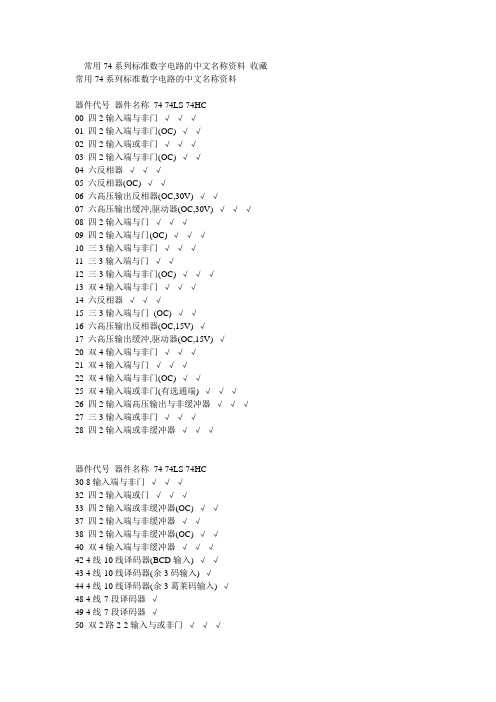
74系列芯片功能表汇总74系列标准数字电路功能表——中文资料名称类别功能7400 TTL 2输入端四与非门7401 TTL 集电极开路2输入端四与非门7402 TTL 2输入端四或非门7403 TTL 集电极开路2输入端四与非门7404 TTL 六反相器7405 TTL 集电极开路六反相器7406 TTL 集电极开路六反相高压驱动器7407 TTL 集电极开路六正相高压驱动器7408 TTL 2输入端四与门7409 TTL 集电极开路2输入端四与门7410 TTL 3输入端3与非门74107 TTL 带清除主从双J-K触发器74109 TTL 带预置清除正触发双J-K触发器7411 TTL 3输入端3与门74112 TTL 带预置清除负触发双J-K触发器7412 TTL 开路输出3输入端三与非门74121 TTL 单稳态多谐振荡器74122 TTL 可再触发单稳态多谐振荡器74123 TTL 双可再触发单稳态多谐振荡器74125 TTL 三态输出高有效四总线缓冲门74126 TTL 三态输出低有效四总线缓冲门7413 TTL 4输入端双与非施密特触发器74132 TTL 2输入端四与非施密特触发器74133 TTL 13输入端与非门74136 TTL 四异或门74138 TTL 3-8线译码器/复工器74139 TTL 双2-4线译码器/复工器7414 TTL 六反相施密特触发器74145 TTL BCD—十进制译码/驱动器7415 TTL 开路输出3输入端三与门74150 TTL 16选1数据选择/多路开关74151 TTL 8选1数据选择器74153 TTL 双4选1数据选择器74154 TTL 4线—16线译码器74155 TTL 图腾柱输出译码器/分配器74156 TTL 开路输出译码器/分配器74157 TTL 同相输出四2选1数据选择器74158 TTL 反相输出四2选1数据选择器7416 TTL 开路输出六反相缓冲/驱动器74160 TTL 可预置BCD异步清除计数器74161 TTL 可予制四位二进制异步清除计数器74162 TTL 可预置BCD同步清除计数器74163 TTL 可予制四位二进制同步清除计数器74164 TTL 八位串行入/并行输出移位寄存器74165 TTL 八位并行入/串行输出移位寄存器74166 TTL 八位并入/串出移位寄存器74169 TTL 二进制四位加/减同步计数器7417 TTL 开路输出六同相缓冲/驱动器74170 TTL 开路输出4×4寄存器堆74173 TTL 三态输出四位D型寄存器74174 TTL 带公共时钟和复位六D触发器74175 TTL 带公共时钟和复位四D触发器74180 TTL 9位奇数/偶数发生器/校验器74181 TTL 算术逻辑单元/函数发生器74185 TTL 二进制—BCD代码转换器74190 TTL BCD同步加/减计数器74191 TTL 二进制同步可逆计数器74192 TTL 可预置BCD双时钟可逆计数器74193 TTL 可预置四位二进制双时钟可逆计数器74194 TTL 四位双向通用移位寄存器74195 TTL 四位并行通道移位寄存器74196 TTL 十进制/二-十进制可预置计数锁存器74197 TTL 二进制可预置锁存器/计数器7420 TTL 4输入端双与非门7421 TTL 4输入端双与门7422 TTL 开路输出4输入端双与非门74221 TTL 双/单稳态多谐振荡器74240 TTL 八反相三态缓冲器/线驱动器74241 TTL 八同相三态缓冲器/线驱动器74243 TTL 四同相三态总线收发器74244 TTL 八同相三态缓冲器/线驱动器74245 TTL 八同相三态总线收发器74247 TTL BCD—7段15V输出译码/驱动器74248 TTL BCD—7段译码/升压输出驱动器74249 TTL BCD—7段译码/开路输出驱动器74251 TTL 三态输出8选1数据选择器/复工器74253 TTL 三态输出双4选1数据选择器/复工器74256 TTL 双四位可寻址锁存器74257 TTL 三态原码四2选1数据选择器/复工器74258 TTL 三态反码四2选1数据选择器/复工器74259 TTL 八位可寻址锁存器/3-8线译码器7426 TTL 2输入端高压接口四与非门74260 TTL 5输入端双或非门74266 TTL 2输入端四异或非门7427 TTL 3输入端三或非门74273 TTL 带公共时钟复位八D触发器74279 TTL 四图腾柱输出S-R锁存器7428 TTL 2输入端四或非门缓冲器74283 TTL 4位二进制全加器74290 TTL 二/五分频十进制计数器74293 TTL 二/八分频四位二进制计数器74295 TTL 四位双向通用移位寄存器74298 TTL 四2输入多路带存贮开关74299 TTL 三态输出八位通用移位寄存器7430 TTL 8输入端与非门7432 TTL 2输入端四或门74322 TTL 带符号扩展端八位移位寄存器74323 TTL 三态输出八位双向移位/存贮寄存器7433 TTL 开路输出2输入端四或非缓冲器74347 TTL BCD—7段译码器/驱动器74352 TTL 双4选1数据选择器/复工器74353 TTL 三态输出双4选1数据选择器/复工器74365 TTL 门使能输入三态输出六同相线驱动器74365 TTL 门使能输入三态输出六同相线驱动器74366 TTL 门使能输入三态输出六反相线驱动器74367 TTL 4/2线使能输入三态六同相线驱动器74368 TTL 4/2线使能输入三态六反相线驱动器7437 TTL 开路输出2输入端四与非缓冲器74373 TTL 三态同相八D锁存器74374 TTL 三态反相八D锁存器74375 TTL 4位双稳态锁存器74377 TTL 单边输出公共使能八D锁存器74378 TTL 单边输出公共使能六D锁存器74379 TTL 双边输出公共使能四D锁存器7438 TTL 开路输出2输入端四与非缓冲器74380 TTL 多功能八进制寄存器7439 TTL 开路输出2输入端四与非缓冲器74390 TTL 双十进制计数器74393 TTL 双四位二进制计数器7440 TTL 4输入端双与非缓冲器7442 TTL BCD—十进制代码转换器74352 TTL 双4选1数据选择器/复工器74353 TTL 三态输出双4选1数据选择器/复工器74365 TTL 门使能输入三态输出六同相线驱动器74366 TTL 门使能输入三态输出六反相线驱动器74367 TTL 4/2线使能输入三态六同相线驱动器74368 TTL 4/2线使能输入三态六反相线驱动器7437 TTL 开路输出2输入端四与非缓冲器74373 TTL 三态同相八D锁存器74374 TTL 三态反相八D锁存器74375 TTL 4位双稳态锁存器74377 TTL 单边输出公共使能八D锁存器74378 TTL 单边输出公共使能六D锁存器74379 TTL 双边输出公共使能四D锁存器7438 TTL 开路输出2输入端四与非缓冲器74380 TTL 多功能八进制寄存器7439 TTL 开路输出2输入端四与非缓冲器74390 TTL 双十进制计数器74393 TTL 双四位二进制计数器7440 TTL 4输入端双与非缓冲器7442 TTL BCD—十进制代码转换器74447 TTL BCD—7段译码器/驱动器7445 TTL BCD—十进制代码转换/驱动器74450 TTL 16:1多路转接复用器多工器74451 TTL 双8:1多路转接复用器多工器74453 TTL 四4:1多路转接复用器多工器7446 TTL BCD—7段低有效译码/驱动器74460 TTL 十位比较器74461 TTL 八进制计数器74465 TTL 三态同相2与使能端八总线缓冲器74466 TTL 三态反相2与使能八总线缓冲器74467 TTL 三态同相2使能端八总线缓冲器74468 TTL 三态反相2使能端八总线缓冲器74469 TTL 八位双向计数器7447 TTL BCD—7段高有效译码/驱动器7448 TTL BCD—7段译码器/内部上拉输出驱动74490 TTL 双十进制计数器7449174498 TTL 八进制移位寄存器7450 TTL 2-3/2-2输入端双与或非门74502 TTL 八位逐次逼近寄存器74503 TTL 八位逐次逼近寄存器7451 TTL 2-3/2-2输入端双与或非门74533 TTL 三态反相八D锁存器74534 TTL 三态反相八D锁存器7454 TTL 四路输入与或非门74540 TTL 八位三态反相输出总线缓冲器7455 TTL 4输入端二路输入与或非门74563 TTL 八位三态反相输出触发器74564 TTL 八位三态反相输出D触发器74573 TTL 八位三态输出触发器74574 TTL 八位三态输出D触发器74645 TTL 三态输出八同相总线传送接收器74670 TTL 三态输出4×4寄存器堆7473 TTL 带清除负触发双J-K触发器7474 TTL 带置位复位正触发双D触发器7476 TTL 带预置清除双J-K触发器7483 TTL 四位二进制快速进位全加器7485 TTL 四位数字比较器7486 TTL 2输入端四异或门7490 TTL 可二/五分频十进制计数器7493 TTL 可二/八分频二进制计数器7495 TTL 四位并行输入\输出移位寄存器7497 TTL 6位同步二进制乘法器常用74系列标准数字电路的中文名称资料器件代号器件名称74 74LS 74HC00 四2输入端与非门√√√01 四2输入端与非门(OC) √√02 四2输入端或非门√√√03 四2输入端与非门(OC) √√04 六反相器√√√05 六反相器(OC) √√06 六高压输出反相器(OC,30V) √√07 六高压输出缓冲,驱动器(OC,30V) √√√08 四2输入端与门√√√09 四2输入端与门(OC) √√√10 三3输入端与非门√√√11 三3输入端与门√√12 三3输入端与非门(OC) √√√13 双4输入端与非门√√√14 六反相器√√√15 三3输入端与门√√16 六高压输出反相器(OC,15V) √17 六高压输出缓冲,驱动器(OC,15V) √20 双4输入端与非门√√√21 双4输入端与门√√√22 双4输入端与非门(OC) √√25 双4输入端或非门(有选通端) √√√26 四2输入端高压输出与非缓冲器√√√27 三3输入端或非门√√√28 四2输入端或非缓冲器√√√30 8输入端与非门√√√32 四2输入端或门√√√33 四2输入端或非缓冲器(OC) √√37 四2输入端与非缓冲器√√38 四2输入端与非缓冲器(OC) √√40 双4输入端与非缓冲器√√√42 4线-10线译码器(BCD输入) √√43 4线-10线译码器(余3码输入) √44 4线-10线译码器(余3葛莱码输入) √48 4线-7段译码器√49 4线-7段译码器√50 双2路2-2输入与或非门√√√√√√51 2路3-3输入,2路2-2输入与或非门52 4路2-3-2-2输入与或门√53 4路2-2-2-2输入与或非门√54 4路2-3-3-2输入与或非门√√55 2路4-4输入与或非门√60 双4输入与扩展器√√61 三3输入与扩展器√62 4路2-3-3-2输入与或扩展器√64 4路4-2-3-2输入与或非门√65 4路4-2-3-2输入与或非门(OC) √70 与门输入J-K触发器√71 与或门输入J-K触发器√72 与门输入J-K触发器√74 双上升沿D型触发器√√78 双D型触发器√√85 四位数值比较器√86 四2输入端异或门√√√87 4位二进制原码/反码√95 4位移位寄存器√101 与或门输入J-K触发器√102 与门输入J-K触发器√107 双主-从J-K触发器√108 双主-从J-K触发器√109 双主-从J-K触发器√110 与门输入J-K触发器√111 双主-从J-K触发器√√112 双下降沿J-K触发器√。

元器件交易网Hitachi CodeJEDECEIAJWeight (reference value)DP-14ConformsConforms0.97 gUnit: mm元器件交易网Hitachi CodeJEDECEIAJWeight (reference value)FP-14DA —Conforms 0.23 g*Dimension including the plating thickness Base material dimension° – 8°Hitachi CodeJEDEC EIAJWeight (reference value)FP-14DN Conforms Conforms 0.13 g° – 8°*Pd platingCautions1.Hitachi neither warrants nor grants licenses of any rights of Hitachi’s or any third party’s patent,copyright, trademark, or other intellectual property rights for information contained in this document.Hitachi bears no responsibility for problems that may arise with third party’s rights, includingintellectual property rights, in connection with use of the information contained in this document.2.Products and product specifications may be subject to change without notice. Confirm that you have received the latest product standards or specifications before final design, purchase or use.3.Hitachi makes every attempt to ensure that its products are of high quality and reliability. However,contact Hitachi’s sales office before using the product in an application that demands especially high quality and reliability or where its failure or malfunction may directly threaten human life or cause risk of bodily injury, such as aerospace, aeronautics, nuclear power, combustion control, transportation,traffic, safety equipment or medical equipment for life support.4.Design your application so that the product is used within the ranges guaranteed by Hitachi particularly for maximum rating, operating supply voltage range, heat radiation characteristics, installationconditions and other characteristics. Hitachi bears no responsibility for failure or damage when used beyond the guaranteed ranges. Even within the guaranteed ranges, consider normally foreseeable failure rates or failure modes in semiconductor devices and employ systemic measures such as fail-safes, so that the equipment incorporating Hitachi product does not cause bodily injury, fire or other consequential damage due to operation of the Hitachi product.5.This product is not designed to be radiation resistant.6.No one is permitted to reproduce or duplicate, in any form, the whole or part of this document without written approval from Hitachi.7.Contact Hitachi’s sales office for any questions regarding this document or Hitachi semiconductor products.Hitachi, Ltd.Semiconductor & Integrated Circuits.Nippon Bldg., 2-6-2, Ohte-machi, Chiyoda-ku, Tokyo 100-0004, Japan Tel: Tokyo (03) 3270-2111 Fax: (03) 3270-5109Copyright ' Hitachi, Ltd., 1999. All rights reserved. Printed in Japan.Hitachi Asia Pte. Ltd.16 Collyer Quay #20-00Hitachi TowerSingapore 049318Tel: 535-2100Fax: 535-1533URLNorthAmerica : http:/Europe : /hel/ecg Asia (Singapore): .sg/grp3/sicd/index.htm Asia (Taiwan): /E/Product/SICD_Frame.htm Asia (HongKong): /eng/bo/grp3/index.htm Japan : http://www.hitachi.co.jp/Sicd/indx.htmHitachi Asia Ltd.Taipei Branch Office3F, Hung Kuo Building. No.167, Tun-Hwa North Road, Taipei (105)Tel: <886> (2) 2718-3666Fax: <886> (2) 2718-8180Hitachi Asia (Hong Kong) Ltd.Group III (Electronic Components)7/F., North Tower, World Finance Centre,Harbour City, Canton Road, Tsim Sha Tsui,Kowloon, Hong Kong Tel: <852> (2) 735 9218Fax: <852> (2) 730 0281 Telex: 40815 HITEC HXHitachi Europe Ltd.Electronic Components Group.Whitebrook ParkLower Cookham Road MaidenheadBerkshire SL6 8YA, United Kingdom Tel: <44> (1628) 585000Fax: <44> (1628) 778322Hitachi Europe GmbHElectronic components Group Dornacher Stra§e 3D-85622 Feldkirchen, Munich GermanyTel: <49> (89) 9 9180-0Fax: <49> (89) 9 29 30 00Hitachi Semiconductor (America) Inc.179 East Tasman Drive,San Jose,CA 95134 Tel: <1> (408) 433-1990Fax: <1>(408) 433-0223For further information write to:。

常用74系列标准数字电路的中文名称资料收藏常用74系列标准数字电路的中文名称资料器件代号器件名称74 74LS 74HC00 四2输入端与非门√√√01 四2输入端与非门(OC) √√02 四2输入端或非门√√√03 四2输入端与非门(OC) √√04 六反相器√√√05 六反相器(OC) √√06 六高压输出反相器(OC,30V) √√07 六高压输出缓冲,驱动器(OC,30V) √√√08 四2输入端与门√√√09 四2输入端与门(OC) √√√10 三3输入端与非门√√√11 三3输入端与门√√12 三3输入端与非门(OC) √√√13 双4输入端与非门√√√14 六反相器√√√15 三3输入端与门(OC) √√16 六高压输出反相器(OC,15V) √17 六高压输出缓冲,驱动器(OC,15V) √20 双4输入端与非门√√√21 双4输入端与门√√√22 双4输入端与非门(OC) √√25 双4输入端或非门(有选通端) √√√26 四2输入端高压输出与非缓冲器√√√27 三3输入端或非门√√√28 四2输入端或非缓冲器√√√器件代号器件名称74 74LS 74HC30 8输入端与非门√√√32 四2输入端或门√√√33 四2输入端或非缓冲器(OC) √√37 四2输入端与非缓冲器√√38 四2输入端与非缓冲器(OC) √√40 双4输入端与非缓冲器√√√42 4线-10线译码器(BCD输入) √√43 4线-10线译码器(余3码输入) √44 4线-10线译码器(余3葛莱码输入) √48 4线-7段译码器√49 4线-7段译码器√50 双2路2-2输入与或非门√√√51 2路3-3输入,2路2-2输入与或非门√√√52 4路2-3-2-2输入与或门√53 4路2-2-2-2输入与或非门√54 4路2-3-3-2输入与或非门√√55 2路4-4输入与或非门√60 双4输入与扩展器√√61 三3输入与扩展器√62 4路2-3-3-2输入与或扩展器√64 4路4-2-3-2输入与或非门√65 4路4-2-3-2输入与或非门(OC) √70 与门输入J-K触发器√71 与或门输入J-K触发器√72 与门输入J-K触发器√器件代号器件名称74 74LS 74HC74 双上升沿D型触发器√√78 双D型触发器√√85 四位数值比较器√86 四2输入端异或门√√√87 4位二进制原码/反码√95 4位移位寄存器√101 与或门输入J-K触发器√102 与门输入J-K触发器√107 双主-从J-K触发器√108 双主-从J-K触发器√74F74是高速的TTL芯片和74HC一样就是速度高109 双主-从J-K触发器√110 与门输入J-K触发器√111 双主-从J-K触发器√√112 双下降沿J-K触发器√113 双下降沿J-K触发器√114 双下降沿J-K触发器√116 双4位锁存器√120 双脉冲同步驱动器√121 单稳态触发器√√√122 可重触发单稳态触发器√√√123 可重触发双稳态触发器√√√125 四总线缓冲器√√√126 四总线缓冲器√√√128 四2输入端或非线驱动器√√√132 四2输入端与非门√√√d触发器芯片有:74HC74 74LS90 双D触发器74LS7474LS364八D触发器(三态)7474、74 H74、74F74、74ALS74、74L74、74LS74A、74S74、74HC73、74C74双D型正沿触发器(带预置和清除端)74174、74LS174、74F174、74ALS174、74S174、74HC174、74C174六D型触发器(带清除端)74175、74LS175、74F175、74ALS175、74S175、74HC175、74C175 四D型触发器(带清除端)74273、74LS273、74S273、74F273、74ALS273、74HC273 八D型触发器(带清除端)74LS364八D触发器(三态)74LS377、74F377、74S3777八D 触发器74LS378、74F378、74S378、74HC378六D 触发器74LS379、74F379、74S379、74HC379八D 触发器。


HD74HC00Quad. 2-input NAND GatesREJ03D0531-0200(Previous ADE-205-403)Rev.2.00Oct 06, 2005 Features• High Speed Operation: t pd = 8.5 ns typ (C L = 50 pF)• High Output Current: Fanout of 10 LSTTL Loads• Wide Operating Voltage: V CC = 2 to 6 V• Low Input Current: 1 µA max• Low Quiescent Supply Current: I CC (static) = 1 µA max (Ta = 25°C)• Ordering InformationPart Name Package TypePackage Code(Previous Code)PackageAbbreviationTaping Abbreviation(Quantity)HD74HC00P DILP-14pin PRDP0014AB-B(DP-14AV)P —HD74HC00FPEL SOP-14 pin (JEITA) PRSP0014DF-B(FP-14DAV)FP EL (2,000 pcs/reel)HD74HC00RPEL SOP-14 pin (JEDEC) PRSP0014DE-A(FP-14DNV)RP EL (2,500 pcs/reel)HD74HC00TELL TSSOP-14pin PTSP0014JA-B(TTP-14DV)T ELL(2,000pcs/reel)Note: Please consult the sales office for the above package availability.Function TableInputs OutputA B YL L HL H HH L HH H LH : High levelL : Low levelPin ArrangementAbsolute Maximum RatingsItem Symbol Ratings UnitSupply voltage range V CC –0.5 to 7.0 V Input / Output voltage Vin, Vout –0.5 to V CC +0.5VInput / Output diode current I IK , I OK ±20 mAOutput current I O±25 mAV CC , GND current I CC or I GND ±50 mAPower dissipationP T 500 mWStorage temperature Tstg –65 to +150 °CNote: The absolute maximum ratings are values, which must not individually be exceeded, and furthermore, no two ofwhich may be realized at the same time.Recommended Operating ConditionsItem Symbol Ratings Unit ConditionsSupply voltage V CC 2 to 6 V Input / Output voltage V IN , V OUT 0 to V CC V Operating temperature Ta –40 to 85 °C 0 to 1000 V CC = 2.0 V 0 to 500V CC = 4.5 V Input rise / fall time *1t r , t f0 to 400nsV CC = 6.0 VNote: 1. This item guarantees maximum limit when one input switches. Waveform: Refer to test circuit of switching characteristics.Electrical CharacteristicsTa = 25°CTa = –40 to+85°CItem Symbol V CC (V) Min Typ Max Min Max UnitTest Conditions2.0 1.5 — — 1.5 — 4.53.15 — — 3.15 —V IH 6.0 4.2 — — 4.2 —V2.0 — — 0.5 — 0.5 4.5 — — 1.35 — 1.35Input voltage V IL6.0 — — 1.8 — 1.8 V 2.0 1.9 2.0 — 1.9 — 4.5 4.4 4.5 — 4.4 — 6.0 5.9 6.0 — 5.9 — I OH = –20 µA 4.5 4.18 — — 4.13 — I OH = –4 mA V OH6.0 5.68 — — 5.63 —V Vin = V IH or V IL I OH = –5.2 mA2.0 — 0.0 0.1 — 0.1 4.5 — 0.0 0.1 — 0.1 6.0 — 0.0 0.1 — 0.1 I OL = 20 µA 4.5 — — 0.26 — 0.33I OL = 4 mAOutput voltage V OL6.0 — — 0.26 — 0.33 V Vin = V IH or V IL I OL = 5.2 mA Input current Iin6.0 — — ±0.1 — ±1.0 µA Vin = V CC or GNDQuiescent supplycurrent I CC 6.0 — — 1.0 — 10 µA Vin = V CC or GND, Iout = 0 µASwitching Characteristics (C L = 50 pF, Input t r = t f = 6 ns)Ta = 25°CTa = –40 to +85°CItem Symbol V CC (V) Min Typ Max MinMax UnitTest Conditions2.0 — — 90 — 115 4.5 — 9 18 —23 t PLH 6.0 — — 15 —20 ns 2.0 — — 90 —115 4.5 — 8 18 — 23 Propagation delay time t PHL 6.0 — — 15 —20ns 2.0 — — 75 —95 4.5 — 7 15 — 19 Output rise time t TLH 6.0 — — 13 —16ns 2.0 — — 75 —95 4.5 — 7 15 — 19 Output fall time t THL 6.0 — — 13 —16 ns Input capacitance Cin — — 5 10 — 10 pFTest CircuitWaveformsPackage Dimensions RENESAS SALES OFFICESRefer to "/en/network" for the latest and detailed information.Renesas Technology America, Inc.450 Holger Way, San Jose, CA 95134-1368, U.S.ATel: <1> (408) 382-7500, Fax: <1> (408) 382-7501Renesas Technology Europe LimitedDukes Meadow, Millboard Road, Bourne End, Buckinghamshire, SL8 5FH, U.K.Tel: <44> (1628) 585-100, Fax: <44> (1628) 585-900Renesas Technology Hong Kong Ltd.7th Floor, North Tower, World Finance Centre, Harbour City, 1 Canton Road, Tsimshatsui, Kowloon, Hong KongTel: <852> 2265-6688, Fax: <852> 2730-6071Renesas Technology Taiwan Co., Ltd.10th Floor, No.99, Fushing North Road, Taipei, TaiwanTel: <886> (2) 2715-2888, Fax: <886> (2) 2713-2999Renesas Technology (Shanghai) Co., Ltd.Unit2607 Ruijing Building, No.205 Maoming Road (S), Shanghai 200020, ChinaTel: <86> (21) 6472-1001, Fax: <86> (21) 6415-2952Renesas Technology Singapore Pte. Ltd.1 Harbour Front Avenue, #06-10, Keppel Bay Tower, Singapore 098632Tel: <65> 6213-0200, Fax: <65> 6278-8001Renesas Technology Korea Co., Ltd.Kukje Center Bldg. 18th Fl., 191, 2-ka, Hangang-ro, Yongsan-ku, Seoul 140-702, KoreaTel: <82> 2-796-3115, Fax: <82> 2-796-2145Renesas Technology Malaysia Sdn. Bhd.Unit 906, Block B, Menara Amcorp, Amcorp Trade Centre, No.18, Jalan Persiaran Barat, 46050 Petaling Jaya, Selangor Darul Ehsan, MalaysiaTel: <603> 7955-9390, Fax: <603> 7955-9510。

HD74LV123ADual Retriggerable Monostable MultivibratorsADE-205-258C (Z)4th EditionJanuary 2001 DescriptionThe HD74LV123A features output pulse-duration control by three methods. In the first method, the A input is low and the B input goes high. In the second method, the B input is high and the A input goes low. In the third method, the A input is low, the B input is high, and the clear (CLR) input goes high.The basic pulse duration is programmed by selecting external resistance and capacitance values.The external timing capacitor must be connected between Cext and Rext/Cext (positive) and an external resistor connected between Rext/Cext and VccTo obtain variable pulse durations, connect an external variable resistance between Rext/Cext and Vcc. Once triggered, the basic pulse duration can be extended by retriggering the gated low-level-active (A) or high-level-active (B) input. Pulse duration can be reduced by taking CLR low.Features•V CC = 2.0 V to 5.5 V operation•All inputs V IH (Max.) = 5.5 V (@V CC = 0 V to 5.5 V)•All outputs V O (Max.) = 5.5 V (@V CC = 0 V)•Output current ±6 mA (@V CC = 3.0 V to 3.6 V), ±12 mA (@V CC = 4.5 V to 5.5 V)HD74LV123ARev.4, Jan. 2001, page 2 of 19Function TableInputs Outputs CLR A B Q Q L X X L H H H X L H H X L LHH L↑H ↓H ↑LHNote:H:High level L:Low level X:Immaterial↑:Low to high transition ↓:High to low transition :High level pulse :Low level pulsePin ArrangementHD74LV123ARev.4, Jan. 2001, page 3 of 19Absolute Maximum RatingsItemSymbol Ratings Unit ConditionsSupply voltage range V CC –0.5 to 7.0V Input voltage range *1V I –0.5 to 7.0V Output voltage range *V O –0.5 to V CC + 0.5V Output: H or L –0.5 to 7.0V CC : OFF Input clamp current I IK –20mA V I < 0Output clamp currentI OK ±50mA V O < 0 or V O > V CC Continuous output current I O±25mA V O = 0 to V CCContinuous current through V CC or GNDI CC or I GND ±50mA Maximum power dissipationat Ta = 25°C (in still air)*3P T785mWSOP 500TSSOPStorage temperatureTstg –65 to 150°CNotes:The absolute maximum ratings are values which must not individually be exceeded, and furthermore,no two of which may be realized at the same time.1.The input and output voltage ratings may be exceeded if the input and output clamp-currentratings are observed.2.This value is limited to 5.5 V maximum.3.The maximum package power dissipation was calculated using a junction temperature of 150°C.HD74LV123ARecommended Operating ConditionsItem Symbol Min Typ Max Unit Conditions Supply voltage range V CC 2.0— 5.5VInput voltage range V I0— 5.5VOutput voltage range V O0—V CC VOutput current I OH——–50µA V CC = 2.0 V——–2mA V CC = 2.3 to 2.7 V——–6V CC = 3.0 to 3.6 V——–12V CC = 4.5 to 5.5 VI OL——50µA V CC = 2.0 V——2mA V CC = 2.3 to 2.7 V——6V CC = 3.0 to 3.6 V——12V CC = 4.5 to 5.5 V Input transition rise or fall rate∆t /∆v0—200ns/V V CC = 2.3 to 2.7 V0—100V CC = 3.0 to 3.6 V0—20V CC = 4.5 to 5.5 V External timing registance Rext5——kΩV CC = 2.0 V1——V CC≥ 2.3 V External timing capacitance Cext—Unlimited—FPower-up ramp rate∆t /∆V CC1——ms/VOperating free-air temperature Ta–40—85°CNote:Unused or floating inputs must be held high or low.Rev.4, Jan. 2001, page 4 of 19HD74LV123A Logic DiagramRev.4, Jan. 2001, page 5 of 19HD74LV123ARev.4, Jan. 2001, page 6 of 19DC Electrical CharacteristicsTa = –40 to 85°CItem Symbol V CC (V)*Min Typ Max Unit Test ConditionsInput voltageV IH2.0 1.5——V2.3 to 2.7V CC × 0.7——3.0 to 3.6V CC × 0.7——4.5 to5.5V CC × 0.7——V IL2.0——0.52.3 to 2.7——V CC × 0.33.0 to 3.6——V CC × 0.34.5 to5.5——V CC × 0.3Output voltageV OHMin to Max V CC – 0.1——VI OH = –50 µA 2.3 2.0——I OH = –2 mA 3.0 2.48——I OH = –6 mA 4.53.8——I OH = –12 mA V OLMin to Max ——0.1I OL = 50 µA 2.3——0.4I OL = 2 mA 3.0——0.44I OL = 6 mA4.5——0.55I OL = 12 mA Input current I IN 0 to5.5——±1µA V IN = 5.5 V or GND Input current Rext / Cext I IN 5.5——±2.5µA V IN = V CC or GND Quiescent supply current I CC 5.5——20µA V IN = V CC or GND, I O = 0Active state supply current (per circuit)∆I CC2.3——220µA V IN = V CC or GND Rext/Cext = 0.5 V CC3.0——2804.5——6505.5——975Output leakage current I OFF 0——5µA V O = 5.5 V InputcapacitanceC IN3.3—4.0—pFV I = V CC or GNDNote:For conditions shown as Min or Max, use the appropriate values under recommended operatingconditions.HD74LV123ARev.4, Jan. 2001, page 7 of 19Switching CharacteristicsV CC = 2.5 ± 0.2 VTa = 25°CTa = –40 to 85°C Item Symbol Min Typ Max Min Max Unit Test Conditions FROM (Input)TO(Output)Propa-gation delay timet PLH t PHL—13.531.41.037.0nsC L = 15 pFA or BQ or Q—16.036.0 1.042.0C L = 50 pF —11.025.0 1.029.5C L = 15 pF CLRQ or Q—13.032.8 1.034.5C L = 50 pF —14.033.4 1.039.0C L = 15 pF CLR Q or Q—16.038.0 1.044.0C L = 50 pF(Trigger)Output pulse widtht wQ—170260—320nsC L = 50 pF,Cext = 28 pF, Rext = 2 k Ω9010011090110µs C L = 50 pF,Cext = 0.01 µF, Rext = 10 k Ω0.91.0 1.10.9 1.1ms C L = 50 pF,Cext = 0.1 µF, Rext = 10 k Ω∆t wQ—±1———%C L = 50 pF Pulse width t w 6.0—— 6.5—ns A , B or CLRRetrigger timet rr—40———ns A , or B(Rext = 1 k Ω, Cext = 100 pF)—1.5———µsA , or B(Rext = 1 k Ω, Cext = 0.01 µF)HD74LV123ARev.4, Jan. 2001, page 8 of 19Switching Characteristics (cont)V CC = 3.3 ± 0.3 VTa = 25°CTa = –40 to 85°C Item Symbol Min Typ Max Min Max Unit Test Conditions FROM (Input)TO(Output)Propa-gation delay timet PLH t PHL—9.720.61.024.0nsC L = 15 pFA or BQ or Q—11.524.1 1.027.5C L = 50 pF —8.015.8 1.018.5C L = 15 pF CLRQ or Q—9.519.3 1.022.0C L = 50 pF —9.922.4 1.026.0C L = 15 pF CLR Q or Q—11.525.9 1.029.5C L = 50 pF(Trigger)Output pulse widtht wQ—150240—300nsC L = 50 pF,Cext = 28 pF, Rext = 2 k Ω9010011090110µs C L = 50 pF,Cext = 0.01 µF, Rext = 10 k Ω0.91.0 1.10.9 1.1ms C L = 50 pF,Cext = 0.1 µF, Rext = 10 k Ω∆t wQ—±1———%C L = 50 pF Pulse width t w 5.0—— 5.0—ns A , B or CLRRetrigger timet rr—30———ns A , or B(Rext = 1 k Ω, Cext = 100 pF)—1.2———µsA , or B(Rext = 1 k Ω, Cext = 0.01 µF)HD74LV123ARev.4, Jan. 2001, page 9 of 19Switching Characteristics (cont)V CC = 5.0 ± 0.5 VTa = 25°CTa = –40 to 85°C Item Symbol Min Typ Max Min Max Unit Test Conditions FROM (Input)TO(Output)Propa-gation delay timet PLH t PHL—7.312.01.014.0nsC L = 15 pFA or BQ or Q—8.514.0 1.016.0C L = 50 pF — 5.99.4 1.011.0C L = 15 pF CLRQ or Q—7.511.4 1.013.0C L = 50 pF —7.312.9 1.015.0C L = 15 pF CLR Q or Q—8.714.9 1.017.0C L = 50 pF(Trigger)Output pulse widtht wQ—140200—240nsC L = 50 pF,Cext = 28 pF, Rext = 2 k Ω9010011090110µs C L = 50 pF,Cext = 0.01 µF, Rext = 10 k Ω0.91.0 1.10.9 1.1ms C L = 50 pF,Cext = 0.1 µF, Rext = 10 k Ω∆t wQ—±1———%C L = 50 pF Pulse width t w 5.0—— 5.0—ns A , B or CLRRetrigger timet rr—20———ns A , or B(Rext = 1 k Ω, Cext = 100 pF)—0.95———µsA , or B(Rext = 1 k Ω, Cext = 0.01 µF)HD74LV123ARev.4, Jan. 2001, page 10 of 19Operating CharacteristicsC L = 50 pFTa = 25°CItem Symbol V CC (V)Min Typ Max Unit Test Conditions Power dissipation capacitanceC PD3.3—74.0—pFf = 10 MHz5.0—86.0—Test CircuitTiming diagramApplication DataPackage DimensionsDisclaimer1.Hitachi neither warrants nor grants licenses of any rights of Hitachi’s or any third party’s patent,copyright, trademark, or other intellectual property rights for information contained in this document.Hitachi bears no responsibility for problems that may arise with third party’s rights, including intellectual property rights, in connection with use of the information contained in this document.2.Products and product specifications may be subject to change without notice. Confirm that you have received the latest product standards or specifications before final design, purchase or use.3.Hitachi makes every attempt to ensure that its products are of high quality and reliability. However,contact Hitachi’s sales office before using the product in an application that demands especially high quality and reliability or where its failure or malfunction may directly threaten human life or cause risk of bodily injury, such as in aerospace, aeronautics, nuclear power, combustion control, transportation,traffic, safety equipment or medical equipment for life support.4.Design your application so that the product is used within the ranges guaranteed by Hitachi particularly for maximum rating, operating supply voltage range, heat radiation characteristics, installationconditions and other characteristics. Hitachi bears no responsibility for failure or damage when used beyond the guaranteed ranges. Even within the guaranteed ranges, consider normally foreseeable failure rates or failure modes in semiconductor devices and employ systemic measures such as fail-safe devices,so that the equipment incorporating the Hitachi product does not cause bodily injury, fire or other consequential damage due to operation of the Hitachi product.5.This product is not designed to be radiation resistant.6.No one is permitted to reproduce or duplicate, in any form, the whole or part of this document without written approval from Hitachi.7.Contact Hitachi’s sales office for any questions regarding this document or Hitachi semiconductor products.Sales OfficesHitachi, Ltd.Semiconductor & Integrated Circuits.Nippon Bldg., 2-6-2, Ohte-machi, Chiyoda-ku, Tokyo 100-0004, Japan Tel: Tokyo (03) 3270-2111 Fax: (03) 3270-5109Copyright Hitachi, Ltd., 2001. All rights reserved. Printed in Japan.Hitachi Asia Ltd. Hitachi Tower16 Collyer Quay #20-00, Singapore 049318Tel : <65>-538-6533/538-8577 Fax : <65>-538-6933/538-3877URL : .sg URLNorthAmerica : /Europe : /hel/ecg Asia : Japan : http://www.hitachi.co.jp/Sicd/indx.htmHitachi Asia Ltd.(Taipei Branch Office)4/F, No. 167, Tun Hwa North Road, Hung-Kuo Building, Taipei (105), Taiwan Tel : <886>-(2)-2718-3666 Fax : <886>-(2)-2718-8180 Telex : 23222 HAS-TPURL : Hitachi Asia (Hong Kong) Ltd.Group III (Electronic Components) 7/F., North Tower, World Finance Centre,Harbour City, Canton Road Tsim Sha Tsui, Kowloon, Hong KongTel : <852>-(2)-735-9218 Fax : <852>-(2)-730-0281URL : Hitachi Europe Ltd.Electronic Components Group.Whitebrook ParkLower Cookham Road MaidenheadBerkshire SL6 8YA, United Kingdom Tel: <44> (1628) 585000Fax: <44> (1628) 585160Hitachi Europe GmbHElectronic Components Group Dornacher Stra§e 3D-85622 Feldkirchen, Munich GermanyTel: <49> (89) 9 9180-0Fax: <49> (89) 9 29 30 00Hitachi Semiconductor (America) Inc.179 East Tasman Drive,San Jose,CA 95134 Tel: <1> (408) 433-1990Fax: <1>(408) 433-0223For further information write to:Colophon 2.0。

HD74LV123ADual Retriggerable Monostable MultivibratorsREJ03D0314–0600Z(Previous ADE-205-258D (Z))Rev.6.00Jun. 02, 2004 DescriptionThe HD74LV123A features output pulse-duration control by three methods. In the first method, the A input is low and the B input goes high. In the second method, the B input is high and the A input goes low. In the third method, the A input is low, the B input is high, and the clear (CLR) input goes high.The basic pulse duration is programmed by selecting external resistance and capacitance values.The external timing capacitor must be connected between Cext and Rext/Cext (positive) and an external resistor connected between Rext/Cext and VccTo obtain variable pulse durations, connect an external variable resistance between Rext/Cext and Vcc.Once triggered, the basic pulse duration can be extended by retriggering the gated low-level-active (A) or high-level-active (B) input. Pulse duration can be reduced by taking CLR low.Features•V CC = 2.0 V to 5.5 V operation•All inputs V IH (Max.) = 5.5 V (@V CC = 0 V to 5.5 V)•All outputs V O (Max.) = 5.5 V (@V CC = 0 V)•Output current ±6 mA (@V CC = 3.0 V to 3.6 V), ±12 mA (@V CC = 4.5 V to 5.5 V)•Ordering InformationPart Name Package Type Package Code PackageAbbreviation Taping Abbreviation (Quantity)HD74LV123AFPEL SOP–16 pin(JEITA)FP–16DAV FP EL (2,000 pcs/reel) HD74LV123ARPEL SOP–16 pin(JEDEC)FP–16DNV RP EL (2,500 pcs/reel) HD74LV123ATELL TSSOP–16 pin TTP–16DAV T ELL (2,000 pcs/reel) Note: Please consult the sales office for the above package availability.Function TableInputs OutputsCLR A B Q Q L X X L H H H X L HL:Low levelX:Immaterial↑:Low to high transition↓:High to low transition:High level pulse:Low level pulsePin ArrangementAbsolute Maximum RatingsItemSymbol Ratings Unit ConditionsSupply voltage range V CC –0.5 to 7.0V Input voltage range*V I –0.5 to 7.0V –0.5 to V CC + 0.5Output: H or L Output voltage range*V O–0.5 to 7.0V V CC : OFF Input clamp current I IK –20mA V I < 0Output clamp currentI OK ±50mA V O < 0 or V O > V CC Continuous output current I O±25mA V O = 0 to V CCContinuous current through V CC or GNDI CC or I GND ±50mA 785SOP Maximum power dissipation at Ta = 25°C (in still air)*3P T 500mW TSSOPStorage temperatureTstg–65 to 150°CNotes:The absolute maximum ratings are values, which must not individually be exceeded, and furthermore, no two ofwhich may be realized at the same time.1.The input and output voltage ratings may be exceeded if the input and output clamp-current ratings areobserved.2.This value is limited to 5.5 V maximum.3.The maximum package power dissipation was calculated using a junction temperature of 150°C.Recommended Operating ConditionsItemSymbol Min Typ Max Unit ConditionsSupply voltage range V CC 2.0— 5.5V Input voltage range V I 0— 5.5V Output voltage range V O 0—V CC V ——–50µA V CC = 2.0 V——–2V CC = 2.3 to 2.7 V ——–6V CC = 3.0 to 3.6 V I OH——–12mAV CC = 4.5 to 5.5 V ——50µA V CC = 2.0 V——2V CC = 2.3 to 2.7 V ——6V CC = 3.0 to 3.6 V Output currentI OL——12mAV CC = 4.5 to 5.5 V 0—200V CC = 2.3 to 2.7 V 0—100V CC = 3.0 to 3.6 V Input transition rise or fall rate ∆t /∆v 0—20ns/VV CC = 4.5 to 5.5 V 5——V CC = 2.0 V External timing resistance Rext 1——k ΩV CC ≥ 2.3 VExternal timing capacitance Cext —Unlimited —F Power-up ramp rate∆t /∆V CC 1——ms/V Operating free-air temperatureTa–40—85°CNote:Unused or floating inputs must be held high or low.Logic DiagramDC Electrical CharacteristicsTa = –40 to 85°CItem Symbol V CC (V)*Min Typ Max Unit Test Conditions2.01.5——2.3 to 2.7V CC × 0.7——3.0 to 3.6V CC × 0.7——V IH4.5 to5.5V CC × 0.7——2.0——0.52.3 to 2.7——V CC × 0.33.0 to 3.6——V CC × 0.3Input voltageV IL4.5 to5.5——V CC × 0.3VMin to Max V CC – 0.1——I OH = –50 µA 2.3 2.0——I OH = –2 mA 3.0 2.48——I OH = –6 mA V OH 4.53.8——I OH = –12 mA Min to Max ——0.1I OL = 50 µA 2.3——0.4I OL = 2 mA 3.0——0.44I OL = 6 mA Output voltage V OL4.5——0.55VI OL = 12 mAInput current I IN 0 to 5.5——±1µA V IN = 5.5 V or GND Input current Rext / Cext I IN 5.5——±2.5µA V IN = V CC or GND Quiescent supply currentI CC 5.5——20µA V IN = V CC or GND, I O = 02.3——2203.0——2804.5——650Active state supply current (per circuit)∆I CC5.5——975µAV IN = V CC or GND Rext/Cext = 0.5 V CCOutput leakage currentI OFF 0——5µA V I or V O = 0 V to 5.5 V Input capacitanceC IN3.3—4.0—pFV I = V CC or GNDNote:For conditions shown as Min or Max, use the appropriate values under recommended operating conditions.Switching CharacteristicsV CC = 2.5 ± 0.2 VTa = 25°CTa = –40 to 85°C Item Symbol Min Typ Max Min Max Unit TestConditionsFROM (Input)TO(Output)—13.531.4 1.037.0C L = 15 pF —16.036.0 1.042.0C L = 50 pF A or B Q or Q —11.025.0 1.029.5C L = 15 pF —13.032.8 1.034.5C L = 50 pF —14.033.4 1.039.0C L = 15 pF Propagation delay timet PLH t PHL—16.038.0 1.044.0nsC L = 50 pFCLR (Trigger)Q or Q—170260—320ns C L = 50 pF, Cext = 28 pF, Rext = 2 k Ω9010011090110µs C L = 50 pF,Cext = 0.01 µF, Rext = 10 k Ωt wQ0.91.0 1.10.9 1.1ms C L = 50 pF,Cext = 0.1 µF, Rext = 10 k ΩOutput pulse width∆t wQ —±1———%C L = 50 pF Pulse width t w 6.0—— 6.5—ns A , B or CLR—40———ns A , or B(Rext = 1 k Ω, Cext = 100 pF)Retrigger timet rr—1.5———µsA , or B(Rext = 1 k Ω, Cext = 0.01 µF)V CC = 3.3 ± 0.3 VTa = 25°CTa = –40 to 85°C Item Symbol Min Typ Max Min Max Unit TestConditions FROM (Input)TO(Output)—9.720.6 1.024.0C L = 15 pF —11.524.1 1.027.5C L = 50 pF A or B Q or Q —8.015.8 1.018.5C L = 15 pF —9.519.3 1.022.0C L = 50 pF CLR Q or Q —9.922.4 1.026.0C L = 15 pF Propagation delay timet PLH t PHL—11.525.9 1.029.5nsC L = 50 pF(Trigger)Q or Q—150240—300ns C L = 50 pF, Cext = 28 pF, Rext = 2 k Ω9010011090110µs C L = 50 pF,Cext = 0.01 µF, Rext = 10 k Ωt wQ0.91.0 1.10.9 1.1ms C L = 50 pF,Cext = 0.1 µF, Rext = 10 k ΩOutput pulse width∆t wQ —±1———%C L = 50 pF Pulse width t w 5.0—— 5.0—ns A , B or CLR—30———ns A , or B(Rext = 1 k Ω, Cext = 100 pF)Retrigger timet rr—1.2———µsA , or B(Rext = 1 k Ω, Cext = 0.01 µF)Switching Characteristics (cont)V CC = 5.0 ± 0.5 VTa = 25°CTa = –40 to 85°C Item Symbol Min Typ Max Min Max Unit TestConditionsFROM (Input)TO(Output)—7.312.0 1.014.0C L = 15 pF —8.514.0 1.016.0C L = 50 pF A or B Q or Q — 5.99.4 1.011.0C L = 15 pF —7.511.4 1.013.0C L = 50 pF —7.312.9 1.015.0C L = 15 pF Propagation delay timet PLH t PHL—8.714.9 1.017.0nsC L = 50 pFCLR (Trigger)Q or Q—140200—240ns C L = 50 pF, Cext = 28 pF, Rext = 2 k Ω9010011090110µs C L = 50 pF,Cext = 0.01 µF, Rext = 10 k Ωt wQ0.91.0 1.10.9 1.1ms C L = 50 pF,Cext = 0.1 µF, Rext = 10 k ΩOutput pulse width∆t wQ —±1———%C L = 50 pF Pulse width t w 5.0—— 5.0—ns A , B or CLR—20———ns A , or B(Rext = 1 k Ω, Cext = 100 pF)Retrigger timet rr—0.95———µsA , or B(Rext = 1 k Ω, Cext = 0.01 µF)Operating CharacteristicsC L = 50 pFTa = 25°CItemSymbol V CC (V)Min Typ Max Unit Test Conditions 3.3—74.0—Power dissipation capacitanceC PD5.0—86.0—pFf = 10 MHzTest CircuitTiming diagramApplication DataPackage Dimensions RENESAS SALES OFFICESRenesas Technology America, Inc.450 Holger Way, San Jose, CA 95134-1368, U.S.ATel: <1> (408) 382-7500 Fax: <1> (408) 382-7501Renesas Technology Europe Limited.Dukes Meadow, Millboard Road, Bourne End, Buckinghamshire, SL8 5FH, United KingdomTel: <44> (1628) 585 100, Fax: <44> (1628) 585 900Renesas Technology Europe GmbHDornacher Str. 3, D-85622 Feldkirchen, GermanyTel: <49> (89) 380 70 0, Fax: <49> (89) 929 30 11Renesas Technology Hong Kong Ltd.7/F., North Tower, World Finance Centre, Harbour City, Canton Road, Hong KongTel: <852> 2265-6688, Fax: <852> 2375-6836Renesas Technology Taiwan Co., Ltd.FL 10, #99, Fu-Hsing N. Rd., Taipei, TaiwanTel: <886> (2) 2715-2888, Fax: <886> (2) 2713-2999Renesas Technology (Shanghai) Co., Ltd.26/F., Ruijin Building, No.205 Maoming Road (S), Shanghai 200020, ChinaTel: <86> (21) 6472-1001, Fax: <86> (21) 6415-2952Renesas Technology Singapore Pte. Ltd.1, Harbour Front Avenue, #06-10, Keppel Bay Tower, Singapore 098632Tel: <65> 6213-0200, Fax: <65> 6278-8001Colophon .1.0。

HD74AC107/HD74ACT107Dual JK Flip-Flop (with Separate Clear and Clock)ADE-205-363 (Z)1st. EditionSep. 2000 DescriptionThe HD74AC107/HD74ACT107 dual JK master/slave flip-flops have a separate clock for each flip-flop. Inputs to the master section are controlled by the clock pulse. The clock pulse also regulates the state of the coupling transistors which connect the master and slave sections. The sequence of operation is as follows: 1) isolate slave from master; 2) enter information from J and K inputs to master; 3) disable J and K inputs;4) transfer information from master to slave.Features• Outputs Source/Sink 24 mA• HD74ACT107 has TTL-Compatible InputsPin ArrangementHD74AC107/HD74ACT1072Logic SymbolPin NamesJ 1, J 2, K 1, K 2Data InputsCP 1, CP 2Clock Pulse Inputs (Active Falling Edge)C D1, C D2Direct Clear Inputs (Active Low)Q 1, Q 2, Q 1, Q 2OutputsTruth TableInputs Outputs @ t n @ t n + 1J K Q L L Qn L H L H L H H HQ nH :High Voltage Level L :Low Voltage Levelt n :Bit time before clock pulse.t n + 1:Bit time after clock pulse.HD74AC107/HD74ACT1073Logic DiagramDC Characteristics (unless otherwise specified)ItemSymbol Max Unit ConditionMaximum quiescent supply current I CC 40µA V IN = V CC or ground, V CC = 5.5 V,Ta = Worst caseMaximum quiescent supply current I CC 4.0µA V IN = V CC or ground, V CC = 5.5 V,Ta = 25°CMaximum additional I CC /input (HD74ACT107)I CCT1.5mAV IN = V CC – 2.1 V, V CC = 5.5 V Ta = Worst caseHD74AC107/HD74ACT1074AC Characteristics: HD74AC107Ta = +25°C C L = 50 pFTa = –40°C to +85°C C L = 50 pF ItemSymbol V CC (V)*1Min Typ Max Min Max Unit Maximum clock f max3.3125——100—MHzfrequency 5.0150——125—Propagation delay t PLH 3.3 1.09.513.0 1.014.0ns C P to Q or Q 5.0 1.07.510.0 1.011.0Propagation delay t PHL 3.3 1.010.013.5 1.014.5ns C P to Q or Q 5.0 1.08.010.5 1.011.5Propagation delay t PLH 3.3 1.09.513.0 1.014.0ns C D to Q5.0 1.07.510.0 1.011.0Propagation delay t PHL 3.3 1.09.513.0 1.014.0ns C D to Q 5.01.07.510.01.011.0Note:1.Voltage Range 3.3 is 3.3 V ± 0.3 VVoltage Range 5.0 is 5.0 V ± 0.5 VOperating Requirements: HD74AC107Ta = +25°C C L = 50 pFTa = –40°C to +85°C C L = 50 pFItem Symbol V CC (V)*1Typ Guaranteed MinimumUnit Setup time t su3.3 3.0 5.5 6.0nsJ or k to C P 5.0 2.0 4.0 4.5Hold time t h3.3–1.50.00.0C P to J or k 5.0–0.50.00.0Pulse width t w 3.3 2.0 5.57.0C P or C D5.0 2.0 4.5 5.0Recovery time t rec 3.3 1.5 3.0 3.0C D to C P 5.01.03.03.0Note:1.Voltage Range 3.3 is 3.3 V ± 0.3 VVoltage Range 5.0 is 5.0 V ± 0.5 VHD74AC107/HD74ACT1075AC Characteristics: HD74ACT107Ta = +25°C C L = 50 pFTa = –40°C to +85°C C L = 50 pF ItemSymbol V CC (V)*1Min Typ Max Min Max Unit Maximum clock frequency f max 5.0100——80—MHz Propagation delay C P to Q or Q t PLH 5.0 1.09.512.5 1.013.5nsPropagation delay C P to Q or Q t PHL 5.0 1.010.513.0 1.014.0Propagation delay C D to Qt PLH 5.0 1.08.511.0 1.012.0Propagation delay C D to Q t PHL5.01.08.511.01.012.0Note:1.Voltage Range 5.0 is 5.0 V ± 0.5 VOperating Requirements: HD74ACT107Ta = +25°C C L = 50 pFTa = –40°C to +85°C C L = 50 pFItem Symbol V CC (V)*1Typ Guaranteed MinimumUnit Setup time J or k to C P t su 5.0 2.57.08.0nsHold time C P to J or k t h 5.00.0 1.5 1.5Pulse width C P or C Dt w 5.0 4.57.08.0Recovery time C D to C P t rec5.0—3.03.0Note:1.Voltage Range 5.0 is 5.0 V ± 0.5 VCapacitanceItemSymbol Typ Unit Condition Input capacitanceC IN 4.5pF V CC = 5.5 V Power dissipation capacitanceC PD35.0pFV CC = 5.0 VHD74AC107/HD74ACT107 Package Dimensions6HD74AC107/HD74ACT1077HD74AC107/HD74ACT1078Cautions1.Hitachi neither warrants nor grants licenses of any rights of Hitachi’s or any third party’s patent,copyright, trademark, or other intellectual property rights for information contained in this document.Hitachi bears no responsibility for problems that may arise with third party’s rights, includingintellectual property rights, in connection with use of the information contained in this document.2.Products and product specifications may be subject to change without notice. Confirm that you have received the latest product standards or specifications before final design, purchase or use.3.Hitachi makes every attempt to ensure that its products are of high quality and reliability. However,contact Hitachi’s sales office before using the product in an application that demands especially high quality and reliability or where its failure or malfunction may directly threaten human life or cause risk of bodily injury, such as aerospace, aeronautics, nuclear power, combustion control, transportation,traffic, safety equipment or medical equipment for life support.4.Design your application so that the product is used within the ranges guaranteed by Hitachi particularly for maximum rating, operating supply voltage range, heat radiation characteristics, installationconditions and other characteristics. Hitachi bears no responsibility for failure or damage when used beyond the guaranteed ranges. Even within the guaranteed ranges, consider normally foreseeable failure rates or failure modes in semiconductor devices and employ systemic measures such as fail-safes, so that the equipment incorporating Hitachi product does not cause bodily injury, fire or other consequential damage due to operation of the Hitachi product.5.This product is not designed to be radiation resistant.6.No one is permitted to reproduce or duplicate, in any form, the whole or part of this document without written approval from Hitachi.7.Contact Hitachi’s sales office for any questions regarding this document or Hitachi semiconductor products.Hitachi, Ltd.Semiconductor & Integrated Circuits.Nippon Bldg., 2-6-2, Ohte-machi, Chiyoda-ku, Tokyo 100-0004, Japan Tel: Tokyo (03) 3270-2111 Fax: (03) 3270-5109Copyright © Hitachi, Ltd., 2000. All rights reserved. Printed in Japan.Hitachi Asia Ltd. Hitachi Tower16 Collyer Quay #20-00, Singapore 049318Tel : <65>-538-6533/538-8577 Fax : <65>-538-6933/538-3877URL : .sg URLNorthAmerica : /Europe : /hel/ecg Asia : Japan : http://www.hitachi.co.jp/Sicd/indx.htmHitachi Asia Ltd.(Taipei Branch Office)4/F, No. 167, Tun Hwa North Road, Hung-Kuo Building, Taipei (105), Taiwan Tel : <886>-(2)-2718-3666 Fax : <886>-(2)-2718-8180 Telex : 23222 HAS-TPURL : Hitachi Asia (Hong Kong) Ltd. Group III (Electronic Components) 7/F., North Tower, World Finance Centre,Harbour City, Canton Road Tsim Sha Tsui, Kowloon, Hong KongTel : <852>-(2)-735-9218 Fax : <852>-(2)-730-0281URL : Hitachi Europe Ltd.Electronic Components Group.Whitebrook ParkLower Cookham Road MaidenheadBerkshire SL6 8YA, United Kingdom Tel: <44> (1628) 585000Fax: <44> (1628) 585160Hitachi Europe GmbHElectronic Components Group Dornacher Stra βe 3D-85622 Feldkirchen, Munich GermanyTel: <49> (89) 9 9180-0Fax: <49> (89) 9 29 30 00Hitachi Semiconductor (America) Inc.179 East Tasman Drive,San Jose,CA 95134 Tel: <1> (408) 433-1990Fax: <1>(408) 433-0223For further information write to:Colophon 2.0。


HD74LVC16373A16-bit D-type Transparent Latches with 3-state OutputsADE-205-121B(Z)3rd EditionDecember 1996 DescriptionThe HD74LVC16373A has sixteen D type latches with three state outputs in a 48 pin package. When the latch enable input is high, the Q outputs will follow the D inputs. When the latch enable goes low, data at the D inputs will be retained at the outputs until latch enable returns high again. When a high logic level is applied to the output control input (1G, 2G), all outputs go to a high impedance state, regardless of what signals are present at the other inputs and the state of the storage elements. Low voltage and high speed operation is suitable at the battery drive product (note type personal computer) and low power consumption extends the life of a battery for long time operation.Features• V CC = 2.0 V to 5.5 V• All inputs V IH (Max.) = 5.5 V (@V CC = 0 V to 5.5 V)• All outputs V OUT (Max.) = 5.5 V (@V CC = 0 V or output off state)• Typical V OL ground bounce < 0.8 V (@V CC = 3.3 V, Ta = 25°C)• Typical V OH undershoot > 2.0 V (@V CC = 3.3 V, Ta = 25°C)• High output current ±24 mA (@V CC = 3.0 V to 5.5 V)Function TableInputsG LE D Output QH X X ZL H L LL H H HL L X QlevelH: HighL:Low levelX:ImmaterialZ:High impedanceQ:Level of Q before the indicated steady input conditions were established.HD74LVC16373A Pin Arrangement2HD74LVC16373A3Absolute Maximum RatingsItemSymbol Ratings Unit ConditionsSupply voltage V CC –0.5 to 6.0V Input diode current I IK –50mA V I = –0.5 V Input voltage V I –0.5 to 6.0V Output diode current I OK –50mA V O = –0.5 V 50mA V O = V CC +0.5 V Output voltage V O –0.5 to V CC +0.5V Output "H" or "L"–0.5 to 6.0V Output "Z" or V CC :OFF Output current I O±50mA V CC , GND current / pin I CC or I GND 100mA Storage temperatureTstg–65 to +150°CNote:The absolute maximum ratings are values which must not individually be exceeded, and furthermore,no two of which may be realized at the same time.Recommended Operating ConditonsItemSymbol Ratings Unit Conditions Supply voltage V CC 1.5 to 5.5V Data hold 2.0 to 5.5V At operation Input / output voltageV I 0 to 5.5V G , LE, D V O0 to V CC V Output "H" or "L"0 to 5.5V Output "Z" or V CC :OFFOperating temperature Ta –40 to 85°C Output currentI OH –12mA V CC = 2.7 V –24*2mA V CC = 3.0 V to 5.5 V I OL12mA V CC = 2.7 V 24*2mA V CC = 3.0 V to 5.5 V Input rise / fall time *1t r , t f10ns/VNotes: 1.This item guarantees maximum limit when one input switches.Waveform : Refer to test circuit of switching characteristics.2.duty cycle ≤ 50%HD74LVC16373A4Electrical CharacteristicsTa = –40 to 85°CItem Symbol V CC (V)Min Max Unit Test Conditions Input voltageV IH 2.7 to 3.6 2.0—V 4.5 to 5.5V CC ×0.7—V V IL2.7 to3.6—0.8V4.5 to5.5—V CC ×0.3V Output voltageV OH2.7 to 5.5V CC –0.2—V I OH = –100 µA 2.7 2.2—V I OH = –12 mA3.0 2.4—V 3.0 2.2—V I OH = –24 mA4.53.8—V V OL2.7 to 5.5—0.2V I OL = 100 µA 2.7—0.4V I OL = 12 mA3.0—0.55V I OL = 24 mA4.5—0.55V Input currentI IN 0 to 5.5—±5.0µA V IN = 5.5 V or GND Off state output current I OZ 2.7 to 5.5—±5.0µA V IN = V CC , GNDV OUT = 5.5 V or GND Output leak currentI OFF0—20µA V IN / V OUT = 5.5 V Quiescent supply current I CC2.7 to3.6—±20µA V IN / V OUT = 3.6 to 5.5 V 2.7 to 5.5—20µA V IN = V CC or GND∆I CC3.0 to 3.6—500µAV IN = one input at(V CC –0.6)V,other inputs at V CC or GNDHD74LVC16373A5Switching CharacteristicsTa = –40 to 85°CItemSymbol V CC (V)Min Typ Max Unit From (Input)To (Output)Propagation delay timet PLH 2.7——7.7ns DQt PHL 3.3±0.3 1.5—7.0ns 5.0±0.5—— 5.5ns t PLH 2.7——8.0ns LEQt PHL3.3±0.3 2.0—7.0ns 5.0±0.5—— 5.5ns Output enable timet ZH 2.7——8.0ns GQt ZL3.3±0.3 1.5—7.0ns 5.0±0.5—— 6.0ns Output disable timet HZ 2.7——8.0ns GQt LZ3.3±0.3 1.5—7.0ns 5.0±0.5—— 6.0ns Setup timet su2.7 2.0——ns3.3±0.3 2.0——ns 5.0±0.52.0——ns Hold timet h2.7 1.5——ns3.3±0.3 1.5——ns 5.0±0.51.5——ns Pulse widtht w2.73.0——ns 3.3±0.3 3.0——ns 5.0±0.53.0——ns Between output pins skew *1t OSLH 2.7———ns t OSHL3.3±0.3—— 1.0ns 5.0±0.5—— 1.0ns Input capacitance C IN 2.7— 3.0—pF Output capacitance C O2.7—15.0—pFNote:1.This parameter is characterized but not tested.tos LH = | t PLHm – t PLHn |, tos HL = | t PHLm – t PHLn |HD74LVC16373A Test CircuitWaveforms – 16HD74LVC16373A Waveforms – 2Waveforms – 37HD74LVC16373A Waveforms – 48Hitachi CodeJEDECEIAJWeight (reference value)TTP-48DB——0.20 gUnit: mm*Dimension including the plating thickness Base material dimensionCautions1.Hitachi neither warrants nor grants licenses of any rights of Hitachi’s or any third party’s patent,copyright, trademark, or other intellectual property rights for information contained in this document.Hitachi bears no responsibility for problems that may arise with third party’s rights, includingintellectual property rights, in connection with use of the information contained in this document.2.Products and product specifications may be subject to change without notice. Confirm that you have received the latest product standards or specifications before final design, purchase or use.3.Hitachi makes every attempt to ensure that its products are of high quality and reliability. However,contact Hitachi’s sales office before using the product in an application that demands especially high quality and reliability or where its failure or malfunction may directly threaten human life or cause risk of bodily injury, such as aerospace, aeronautics, nuclear power, combustion control, transportation,traffic, safety equipment or medical equipment for life support.4.Design your application so that the product is used within the ranges guaranteed by Hitachi particularly for maximum rating, operating supply voltage range, heat radiation characteristics, installationconditions and other characteristics. Hitachi bears no responsibility for failure or damage when used beyond the guaranteed ranges. Even within the guaranteed ranges, consider normally foreseeable failure rates or failure modes in semiconductor devices and employ systemic measures such as fail-safes, so that the equipment incorporating Hitachi product does not cause bodily injury, fire or other consequential damage due to operation of the Hitachi product.5.This product is not designed to be radiation resistant.6.No one is permitted to reproduce or duplicate, in any form, the whole or part of this document without written approval from Hitachi.7.Contact Hitachi’s sales office for any questions regarding this document or Hitachi semiconductor products.Hitachi, Ltd.Semiconductor & Integrated Circuits.Nippon Bldg., 2-6-2, Ohte-machi, Chiyoda-ku, Tokyo 100-0004, Japan Tel: Tokyo (03) 3270-2111 Fax: (03) 3270-5109Copyright ' Hitachi, Ltd., 1999. All rights reserved. Printed in Japan.Hitachi Asia Pte. Ltd.16 Collyer Quay #20-00Hitachi TowerSingapore 049318Tel: 535-2100Fax: 535-1533URLNorthAmerica : http:/Europe : /hel/ecg Asia (Singapore): .sg/grp3/sicd/index.htm Asia (Taiwan): /E/Product/SICD_Frame.htm Asia (HongKong): /eng/bo/grp3/index.htm Japan : http://www.hitachi.co.jp/Sicd/indx.htmHitachi Asia Ltd.Taipei Branch Office3F, Hung Kuo Building. No.167, Tun-Hwa North Road, Taipei (105)Tel: <886> (2) 2718-3666Fax: <886> (2) 2718-8180Hitachi Asia (Hong Kong) Ltd.Group III (Electronic Components)7/F., North Tower, World Finance Centre,Harbour City, Canton Road, Tsim Sha Tsui,Kowloon, Hong Kong Tel: <852> (2) 735 9218Fax: <852> (2) 730 0281 Telex: 40815 HITEC HXHitachi Europe Ltd.Electronic Components Group.Whitebrook ParkLower Cookham Road MaidenheadBerkshire SL6 8YA, United Kingdom Tel: <44> (1628) 585000Fax: <44> (1628) 778322Hitachi Europe GmbHElectronic components Group Dornacher Stra§e 3D-85622 Feldkirchen, Munich GermanyTel: <49> (89) 9 9180-0Fax: <49> (89) 9 29 30 00Hitachi Semiconductor (America) Inc.179 East Tasman Drive,San Jose,CA 95134 Tel: <1> (408) 433-1990Fax: <1>(408) 433-0223For further information write to:。
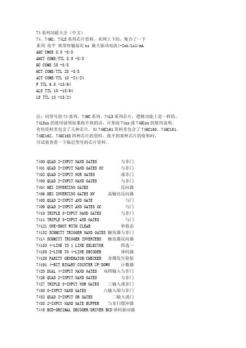
74系列功能大全(中文)74、74HC、74LS系列芯片资料,从网上下的,集合了一下系列电平典型传输延迟ns 最大驱动电流(-Ioh/Lol)mAAHC CMOS 8.5 -8/8AHCT COMS/TTL 8.5 -8/8HC COMS 25 -8/8HCT COMS/TTL 25 -8/8ACT COMS/TTL 10 -24/24F TTL 6.5 -15/64ALS TTL 10 -15/64LS TTL 18 -15/24注:同型号的74系列、74HC系列、74LS系列芯片,逻辑功能上是一样的。
74LSxx的使用说明如果找不到的话,可参阅74xx或74HCxx的使用说明。
有些资料里包含了几种芯片,如74HC161资料里包含了74HC160、74HC161、74HC162、74HC163四种芯片的资料。
找不到某种芯片的资料时,可试着查看一下临近型号的芯片资料。
7400 QUAD 2-INPUT NAND GATES 与非门7401 QUAD 2-INPUT NAND GATES OC 与非门7402 QUAD 2-INPUT NOR GATES 或非门7403 QUAD 2-INPUT NAND GATES 与非门7404 HEX INVERTING GATES 反向器7406 HEX INVERTING GATES HV 高输出反向器7408 QUAD 2-INPUT AND GATE 与门7409 QUAD 2-INPUT AND GATES OC 与门7410 TRIPLE 3-INPUT NAND GATES 与非门7411 TRIPLE 3-INPUT AND GATES 与门74121 ONE-SHOT WITH CLEAR 单稳态74132 SCHMITT TRIGGER NAND GATES 触发器与非门7414 SCHMITT TRIGGER INVERTERS 触发器反向器74153 4-LINE TO 1 LINE SELECTOR 四选一74155 2-LINE TO 4-LINE DECODER 译码器74180 PARITY GENERATOR/CHECKER 奇偶发生检验74191 4-BIT BINARY COUNTER UP/DOWN 计数器7420 DUAL 4-INPUT NAND GATES 双四输入与非门7426 QUAD 2-INPUT NAND GATES 与非门7427 TRIPLE 3-INPUT NOR GATES 三输入或非门7430 8-INPUT NAND GATES 八输入端与非门7432 QUAD 2-INPUT OR GATES 二输入或门7438 2-INPUT NAND GATE BUFFER 与非门缓冲器7445 BCD-DECIMAL DECODER/DRIVER BCD译码驱动器7474 D-TYPE FLIP-FLOP D型触发器7475 QUAD LATCHES 双锁存器7476 J-K FLIP-FLOP J-K触发器7485 4-BIT MAGNITUDE COMPARATOR 四位比较器7486 2-INPUT EXCLUSIVE OR GATES 双端异或门74HC00 QUAD 2-INPUT NAND GATES 双输入与非门74HC02 QUAD 2-INPUT NOR GATES 双输入或非门74HC03 2-INPUT OPEN-DRAIN NAND GATES 与非门74HC04 HEX INVERTERS 六路反向器74HC05 HEX INVERTERS OPEN DRAIN 六路反向器74HC08 2-INPUT AND GATES 双输入与门74HC107 J-K FLIP-FLOP WITH CLEAR J-K触发器74HC109A J-K FLIP-FLOP W/PRESET J-K触发器74HC11 TRIPLE 3-INPUT AND GATES 三输入与门74HC112 DUAL J-K FLIP-FLOP 双J-K触发器74HC113 DUAL J-K FLIP-FLOP PRESET 双JK触发器74HC123A RETRIGGERABLE MONOSTAB 可重触发单稳74HC125 TRI-STATE QUAD BUFFERS 四个三态门74HC126 TRI-STATE QUAD BUFFERS 六三态门74HC132 2-INPUT TRIGGER NAND 施密特触发与非门74HC133 13-INPUT NAND GATES 十三输入与非门74HC137 3-TO-8 DECODERS W/LATCHES 3-8线译码器74HC138 3-8 LINE DECODER 3线至8线译码器74HC139 2-4 LINE DECODER 2线至4线译码器74HC14 TRIGGERED HEX INVERTER 六触发反向器74HC147 10-4 LINE PRIORITY ENCODER 10-4编码器74HC148 8-3 LINE PRIORITY ENCODER 8-3编码器74HC149 8-8 LINE PRIORITY ENCODER 8-8编码器74HC151 8-CHANNEL DIGITAL MUX 8通道多路器74HC153 DUAL 4-INPUT MUX 双四输入多路器74HC154 4-16 LINE DECODER 4线至16线译码器74HC155 2-4 LINE DECODER 2线至4线译码器74HC157 QUAD 2-INPUT MUX 四个双端多路器74HC161 BINARY COUNTER 二进制计数器74HC163 DECADE COUNTERS 十进制计数器74HC164 SERIAL-PARALLEL SHIFT REG 串入并出74HC165 PARALLEL-SERIAL SHIFT REG 并入串出74HC166 SERIAL-PARALLEL SHIFT REG 串入并出74HC173 TRI-STATE D FLIP-FLOP 三态D触发器74HC174 HEX D FLIP-FLOP W/CLEAR 六D触发器74HC175 HEX D FLIP-FLOP W/CLEAR 六D触发器74HC181 ARITHMETIC LOGIC UNIT 算术逻辑单元74HC182 LOOK AHEAD CARRYGENERATR 进位发生器74HC190 BINARY UP/DN COUNTER 二进制加减计数器74HC191 DECADE UP/DN COUNTER 十进制加减计数器74HC192 DECADE UP/DN COUNTER 十进制加减计数器74HC193 BINARY UP/DN COUNTER 二进制加减计数器74HC194 4BIT BI-DIR SHIFT 4位双向移位寄存器74HC195 4BIT PARALLEL SHIFT 4位并行移位寄存器74HC20 QUAD 4-INPUT NAND GATE 四个四入与非门74HC221A NON-RETRIG MONOSTAB 不可重触发单稳74HC237 3-8 LINE DECODER 地址锁3线至8线译码器74HC242/243 TRI-STAT TRANSCEIVER 三态收发器74HC244 OCTAL 3-STATE BUFFER 八个三态缓冲门74HC245 OCTAL 3-STATE TRANSCEIVER 三态收发器74HC251 8-CH 3-STATE MUX 8路3态多路器74HC253 DUAL 4-CH 3-STATE MUX 4路3态多路器74HC257 QUAD 2-CH 3-STATE MUX 4路3态多路器74HC258 2-CH 3-STATE MUX 2路3态多路器74HC259 3-8 LINE DECODER 8位地址锁存译码器74HC266A 2-INPUT EXCLUSIVE NOR GATE 异或非74HC27 TRIPLE 3-INPUT NOR GATE三个3输入或非门74HC273 OCTAL D FLIP-FLOP CLEAR 8路D触发器74HC280 9BIT ODD/EVEN GENERATOR 奇偶发生器74HC283 4BIT BINARY ADDER CARRY 四位加法器74HC299 3-STATE UNIVERSAL SHIFT 三态移位寄存74HC30 8-INPUT NAND GATE 8输入端与非门74HC32 QUAD 2-INPUT OR GATE 四个双端或门74HC34 NON-INVERTER 非反向器74HC354 8-CH 3-STATE MUX 8路3态多路器74HC356 8-CH 3-STATE MUX 8路3态多路器74HC365 HEX 3-STATE BUFFER 六个三态缓冲门74HC366 3-STATE BUFFER INVERTER 缓冲反向器74HC367 3-STATE BUFFER INVERTER 缓冲反向器74HC368 3-STATE BUFFER INVERTER 缓冲反向器74HC373 3-STATE OCTAL D LATCHES 三态D型锁存器74HC374 3-STATE OCTAL D FLIPFLOP 三态D触发器74HC393 4-BIT BINARY COUNTER 4位二进制计数器74HC4016 QUAD ANALOG SWITCH 四路模拟量开关74HC4020 14-Stage Binary Counter 14输出计数器74HC4017 Decade Counter/Divider with 10 Decoded Outputs 十进制计数器带10个译码输出端74HC4040 12 Stage Binary Counter 12出计数器74HC4046 PHASE LOCK LOOP 相位监测输出器74HC4049 LEVEL DOWN CONVERTER 电平变低器74HC4050 LEVEL DOWN CONVERTER 电平变低器74HC4051 8-CH ANALOG MUX 8通道多路器74HC4052 4-CH ANALOG MUX 4通道多路器74HC4053 2-CH ANALOG MUX 2通道多路器74HC4060 14-STAGE BINARY COUNTER 14阶BIN计数74HC4066 QUAD ANALOG MUX 四通道多路器74HC4075 TRIPLE 3-INPUT OR GATE 3输入或门74HC42 BCD TO DECIMAL BCD转十进制译码器74HC423A RETRIGGERABLE MONOSTAB 可重触发单稳74HC4511 BCD-7 SEG DRIVER/DECODER 7段译码器74HC4514 4-16 LINE DECODER 4至16线译码器74HC4538A RETRIGGERAB MONOSTAB 可重触发单稳74HC4543 LCD BCD-7 SEG LCD用的BCD-7段译码驱动74HC51 AND OR GATE INVERTER 与或非门74HC521 8BIT MAGNITUDE COMPARATOR 判决定路74HC533 3-STATE D LATCH 三态D锁存器74HC534 3-STATE D FLIP-FLOP 三态D型触发器74HC540 3-STATE BUFFER 三态缓冲器74HC541 3-STATE BUFFER INVERTER三态缓冲反向器74HC58 DUAL AND OR GATE 与或门74HC589 3STATE 8BIT SHIFT 8位移位寄存三态输出74HC594 8BIT SHIFT REG 8位移位寄存器74HC595 8BIT SHIFT REG 8位移位寄存器出锁存74HC597 8BIT SHIFT REG 8位移位寄存器入锁存74HC620 3-STATE TRANSCEIVER 反向3态收发器74HC623 3-STATE TRANSCEIVER 八路三态收发器74HC640 3-STATE TRANSCEIVER 反向3态收发器74HC643 3-STATE TRANSCEIVER 八路三态收发器74HC646 NON-INVERT BUS TRANSCEIVER 总线收发器74HC648 INVERT BUS TRANCIVER 反向总线收发器74HC688 8BIT MAGNITUDE COMPARATOR 8位判决电路74HC7266 2-INPUT EXCLUSIVE NOR GATE 异或非门74HC73 DUAL J-K FLIP-FLOP W/CLEAR 双JK触发器74HC74A PRESET/CLEAR D FLIP-FLOP 双D触发器74HC75 4BIT BISTABLE LATCH 4位双稳锁存器74HC76 PRESET/CLEAR JK FLIP-FLOP 双JK触发器74HC85 4BIT MAGNITUDE COMPARATOR 4位判决电路74HC86 2INPUT EXCLUSIVE OR GATE 2输入异或门74HC942 BAUD MODEM 300BPS低速调制解调器74HC943 300 BAUD MODEM 300BPS低速调制解调器74LS00 QUAD 2-INPUT NAND GATES 与非门74LS02 QUAD 2-INPUT NOR GATES 或非门74LS03 QUAD 2-INPUT NAND GATES 与非门74LS04 HEX INVERTING GATES 反向器74LS05 HEX INVERTERS OPEN DRAIN 六路反向器74LS08 QUAD 2-INPUT AND GATE 与门74LS09 QUAD 2-INPUT AND GATES OC 与门74LS10 TRIPLE 3-INPUT NAND GATES 与非门74LS109 QUAD 2-INPUT AND GATES OC 与门74LS11 TRIPLE 3-INPUT AND GATES 与门74LS112 DUAL J-K FLIP-FLOP 双J-K触发器74LS113 DUAL J-K FLIP-FLOP PRESET 双JK触发器74LS114 NEGATIVE J-K FLIP-FLOP 负沿J-K触发器74LS122 Retriggerable Monostab 可重触发单稳74LS123 Retriggerable Monostable 可重触发单稳74LS125 TRI-STATE QUAD BUFFERS 四个三态门74LS13 QUAL 4-in NAND TRIGGER 4输入与非触发器74LS160 BCD DECADE 4BIT BIN COUNTERS 计数器74LS136 QUADRUPLE 2-INPUT XOR GATE 异或门74LS138 3-8 LINE DECODER 3线至8线译码器74LS139 2-4 LINE DECODER 2线至4线译码器74LS14 TRIGGERED HEX INVERTER 六触发反向器74HC147 10-4 LINE PRIORITY ENCODER 10-4编码器74HC148 8-3 LINE PRIORITY ENCODER 8-3编码器74HC149 8-8 LINE PRIORITY ENCODER 8-8编码器74LS151 8-CHANNEL DIGITAL MUX 8通道多路器74LS153 DUAL 4-INPUT MUX 双四输入多路器74LS155 2-4 LINE DECODER 2线至4线译码器74LS156 2-4 LINE DECODER/DEMUX 2-4译码器74LS157 QUAD 2-INPUT MUX 四个双端多路器74LS158 2-1 LINE MUX 2-1线多路器74LS160A BINARY COUNTER 二进制计数器74LS161A BINARY COUNTER 二进制计数器74LS162A BINARY COUNTER 二进制计数器74LS163A DECADE COUNTERS 十进制计数器74LS164 SERIAL-PARALLEL SHIFT REG 串入并出74LS168 BI-DIRECT BCD TO DECADE 双向计数器74LS169 4BIT UP/DN BIN COUNTER 四位加减计数器74LS173 TRI-STATE D FLIP-FLOP 三态D触发器74LS174 HEX D FLIP-FLOP W/CLEAR 六D触发器74LS175 HEX D FLIP-FLOP W/CLEAR 六D触发器74LS190 BINARY UP/DN COUNTER 二进制加减计数器74LS191 DECADE UP/DN COUNTER 十进制加减计数器74LS192 DECADE UP/DN COUNTER 十进制加减计数器74LS193 BINARY UP/DN COUNTER 二进制加减计数器74LS194A 4BIT BI-DIR SHIFT 4位双向移位寄存器74LS195A 4BIT PARALLEL SHIFT4位并行移位寄存器74LS20 QUAD 4-INPUT NAND GATE 四个四入与非门74LS21 4-INPUT AND GATE 四输入端与门74LS240 OCTAL 3-STATE BUFFER 八个三态缓冲门74LS244 OCTAL 3-STATE BUFFER 八个三态缓冲门74LS245 OCTAL 3-STATE TRANSCEIVER 三态收发器74LS253 DUAL 4-CH 3-STATE MUX 4路3态多路器74LS256 4BIT ADDRESS LATCH 四位可锁存锁存器74LS257 QUAD 2-CH 3-STATE MUX 4路3态多路器74LS258 2-CH 3-STATE MUX 2路3态多路器74LS27 TRIPLE 3-INPUT NOR GATES 三输入或非门74LS279 QUAD R-S LATCHES 四个RS非锁存器74LS28 QUAD 2-INPUT NOR BUFFER 四双端或非缓冲74LS283 4BIT BINARY ADDER CARRY 四位加法器74LS30 8-INPUT NAND GATES 八输入端与非门74LS32 QUAD 2-INPUT OR GATES 二输入或门74LS352 4-1 LINE SELECTOR/MUX 4-1线选择多路器74LS365 HEX 3-STATE BUFFER 六个三态缓冲门74LS367 3-STATE BUFFER INVERTER 缓冲反向器74LS368A 3-STATE BUFFER INVERTER 缓冲反向器74LS373 OCT LATCH W/3-STATE OUT三态输出锁存器74LS76 Dual JK Flip-Flop w/set 2个JK触发器74LS379 QUAD PARALLEL REG 四个并行寄存器74LS38 2-INPUT NAND GATE BUFFER 与非门缓冲器74LS390 DUAL DECADE COUNTER 2个10进制计数器74LS393 DUAL BINARY COUNTER 2个2进制计数器74LS42 BCD TO DECIMAL BCD转十进制译码器74LS48 BCD-7 SEG BCD-7段译码器74LS49 BCD-7 SEG BCD-7段译码器74LS51 AND OR GATE INVERTER 与或非门74LS540 OCT Buffer/Line Driver 8路缓冲驱动器74LS541 OCT Buffer/LineDriver 8路缓冲驱动器74LS74 D-TYPE FLIP-FLOP D型触发器74LS682 8BIT MAGNITUDE COMPARATOR 8路比较器74LS684 8BIT MAGNITUDE COMPARATOR 8路比较器74LS75 QUAD LATCHES 双锁存器74LS83A 4BIT BINARY ADDER CARRY 四位加法器74LS85 4BIT MAGNITUDE COMPARAT 4位判决电路74LS86 2INPUT EXCLUSIVE OR GATE 2输入异或门74LS90 DECADE/BINARY COUNTER 十/二进制计数器74LS95B 4BIT RIGHT/LEFT SHIFT 4位左右移位寄存74LS688 8BIT MAGNITUDE COMPARAT 8位判决电路74LS136 2-INPUT XOR GATE 2输入异或门74LS651 BUS TRANSCEIVERS 总线收发器74LS653 BUS TRANSCEIVERS 总线收发器74LS670 3-STATE 4-BY-4 REG 3态4-4寄存器74LS73A DUAL J-K FLIP-FLOP W/CLEAR 双JK触发器。
HD74AC123ADual Retriggerable Resettable MultivibratorREJ03D0245–0200Z(Previous ADE-205-365 (Z))Rev.2.00 Jul.16.2004DescriptionEach half of the HD74AC123A features retriggerable capability, complementary dc level triggering and overriding Direct Clear. When a circuit is in the quasi-stable (delay) state, another trigger applied to the inputs (per the Truth Table) will cause the delay period to start again, without disturbing the outputs. By repeating this process, the output pulse period (Q High, Q Low) can be made as long as desired. Alternatively, a delay period can be terminated at any time by a Low signal on C D , which also inhibits triggering. An internal connection from C D to the input gate makes it possible to trigger the circuit by a positive-going signal on C D , as shown in the Truth Table. For timing capacitor values greater than 1000 pF, the output pulse width is defined as follows. Where t w is in ns, R X is in k Ω and C X is in pF. t w = R X C XFeatures• Outputs Source/Sink 24 mA• Ordering InformationPart Name Package Type Package Code Package Abbreviation Taping Abbreviation (Quantity) HD74AC123APDIP-16 pinDP-16E, -16FV P —HD74AC123AFPEL SOP-16 pin (JEITA)FP-16DAVFP EL (2,000 pcs/reel) HD74AC123ARPEL SOP-16 pin (JEDEC) FP-16DNVRPEL (2,500 pcs/reel)Notes: 1. Please consult the sales office for the above package availability. 2. The packages with lead-free pins are distinguished from the conventional products by adding V at the end ofthe package code.Pin Arrangement12A 1B 1V CC R X1C X11615Logic Symbol11(3)V CC = Pin16GND = Pin8 Pin NamesA1, A2Trigger Inputs (Active Falling Edge)B1, B2Trigger Inputs (Active Rising Edge)CD1, CD2Direct Clear Inputs (Active Low)Q1, Q2Positive Pulse OutputsQ1, Q2Negative Pulse OutputsTriggering Truth TableB CDResponseX L No triggerL X No triggerH H TriggerX No triggerH TriggerH TriggerL:Low Voltage LevelX:Immaterial: Low-to-High Transition: High-to-Low TransitionAbsolute Maximum RatingsItemSymbol RatingsUnit Condition Supply voltageV CC –0.5 to 7V –20mA V I = –0.5V DC input diode current I IK 20mA V I = Vcc+0.5V DC input voltage V I –0.5 to Vcc+0.5V –50mA V O = –0.5V DC output diode current I OK 50mA V O = Vcc+0.5VDC output voltageV O –0.5 to Vcc+0.5V DC output source or sink current I O±50mA DC V CC or ground current per output pin I CC , I GND ±50mA Storage temperatureTstg–65 to +150°CRecommended Operating ConditionsItemSymbol RatingsUnitConditionSupply voltageV CC 2 to 6V Input and output voltage V I , V O 0 to V CC V Operating temperature Ta –40 to +85°C V CC = 3.0V V CC = 4.5 V Input rise and fall time (except Schmitt inputs)V IN 30% to 70% V CCtr, tf8ns/VV CC = 5.5 VDC CharacteristicsTa = 25°C Ta = –40 to +85°C ItemSym-bol Vcc (V)min.typ.max.min.max.UnitCondition3.0 2.1 1.5— 2.1—4.5 3.15 2.25— 3.15—V IH5.53.85 2.75— 3.85—V OUT = 0.1 V or V CC –0.1 V3.0— 1.500.9—0.94.5— 2.25 1.35— 1.35Input Voltage V IL5.5— 2.75 1.65— 1.65VV OUT = 0.1 V or V CC –0.1 V3.0 2.9 2.99— 2.9—4.5 4.4 4.49— 4.4—5.5 5.4 5.49— 5.4—V IN = V IL or V IH I OUT = –50 µA 3.0 2.58—— 2.48—I OH = –12 mA 4.53.94—— 3.80—I OH = –24 mA V OH5.5 4.94—— 4.80—V IN = V IL or V IHI OH = –24 mA3.0—0.0020.1—0.14.5—0.0010.1—0.15.5—0.0010.1—0.1V IN = V IL or V IH I OUT = 50 µA 3.0——0.32—0.37I OL = 12 mA 4.5——0.32—0.37I OL = 24 mA Output voltageV OL5.5——0.32—0.37VV IN = V IL or V IHI OL = 24 mAInput leakage currentI IN 5.5——±0.1—±1.0µA V IN = V CC or GND I OLD 5.5———86—mA V OLD = 1.1 V Dynamic output current *I OHD5.5———–75—mA V OHD = 3.85 V Quiescent supply currentI CC 5.5——130—220µA V IN = V CC or ground*Maximum test duration 2.0 ms, one output loaded at a time.AC Characteristics: HD74AC123ATa = +25°C C L = 50 pFTa = –40°C to +85°C C L = 50 pF ItemSymbol V CC (V)*1Min Typ Max Min Max Unit Condition Propagation delay t PLH 3.3 1.0—19.0 1.022.0ns Cext = 0 pFA orB to Q5.01.0—15.0 1.017.0Rest = 5 k ΩPropagation delay t PHL 3.3 1.0—19.0 1.022.0ns A or B to Q5.0 1.0—15.0 1.017.0Propagation delay t PLH 3.3 1.0—15.0 1.018.0ns C Dn to Q5.0 1.0—12.0 1.013.5Propagation delay t PHL3.3 1.0—15.0 1.018.0nsC Dn to Q 5.01.0—12.01.013.5Note:1.Voltage Range 3.3 is 3.3 V ± 0.3 VVoltage Range 5.0 is 5.0 V ± 0.5 VAC Operating Requirements: HD74AC123ATa = +25°C C L = 50 pFTa = –40to +85°C C L = 50 pFItemSymbol V CC (V)*1TypGuaranteed MinimumUnit Condition Pulse width t w 3.3— 5.07.0ns Cext = 0 pFA orB orC Dn 5.0— 4.5 5.0Rext = 5 k ΩRecovery timet rec3.3—2.0 2.0nsC Dn to A or B5.0— 2.02.0Note: 1.Voltage Range 3.3 is 3.3 V ± 0.3 VVoltage Range 5.0 is 5.0 V ± 0.5 VTa = +25°C C L = 50 pFTa = –40°C to +85°C C L = 50 pF ItemSymbol V CC (V)*1Min Typ Max Min Max Unit Condition Output pulse width T WQ 3.3—————ms Cext = 0.1 µF 5.00.90— 1.100.85 1.15Rext = 10 k ΩMinimum outputT WQ(min)3.3190—350170380nsCext = 28 pFpulse width 5.0160—300140330Rext = 2 k ΩNote: 1.Voltage Range 3.3 is 3.3 V ± 0.3 VVoltage Range 5.0 is 5.0 V ± 0.5 VCext and Rext should be connected as close to the IC terminals as possible, in order to prevent malfunction.Package Dimensions5.2.54 M i n 0.51 M i nPackage Code JEDEC JEITAMass (reference value)DP-16E Conforms Conforms 1.05 g2.54 ± 0.250.48 ± 0.10.25+ 0.1– 0.050˚ – 15˚1618919.220.32 Max6.37.4 M a x5.06 M a x0.891.37.62Package Code JEDECJEITAMass (reference value)FP-16DAV —Conforms 0.24 g*Ni/Pd/Au plating*0.40 ± 0.060.120.15M1.27169180.150.25M1.75Max3.95*.2±.59.90˚– 8˚10.3 Max+ 0.10– 0.306.10+ 0.67– 0.200.60+.11–.4.14*0.40 ± 0.060.635 Max 1.08As of January, 2003 RENESAS SALES OFFICESRenesas Technology America, Inc.450 Holger Way, San Jose, CA 95134-1368, U.S.ATel: <1> (408) 382-7500 Fax: <1> (408) 382-7501Renesas Technology Europe Limited.Dukes Meadow, Millboard Road, Bourne End, Buckinghamshire, SL8 5FH, United KingdomTel: <44> (1628) 585 100, Fax: <44> (1628) 585 900Renesas Technology Europe GmbHDornacher Str. 3, D-85622 Feldkirchen, GermanyTel: <49> (89) 380 70 0, Fax: <49> (89) 929 30 11Renesas Technology Hong Kong Ltd.7/F., North Tower, World Finance Centre, Harbour City, Canton Road, Hong KongTel: <852> 2265-6688, Fax: <852> 2375-6836Renesas Technology Taiwan Co., Ltd.FL 10, #99, Fu-Hsing N. Rd., Taipei, TaiwanTel: <886> (2) 2715-2888, Fax: <886> (2) 2713-2999Renesas Technology (Shanghai) Co., Ltd.26/F., Ruijin Building, No.205 Maoming Road (S), Shanghai 200020, ChinaTel: <86> (21) 6472-1001, Fax: <86> (21) 6415-2952Renesas Technology Singapore Pte. Ltd.1, Harbour Front Avenue, #06-10, Keppel Bay Tower, Singapore 098632Tel: <65> 6213-0200, Fax: <65> 6278-8001© 2004. Renesas Technology Corp., All rights reserved. Printed in Japan.Colophon .1.0。