Effectiveness and Safety of Double-balloon Catheter versus Intra-amniotic Injection of Eth
- 格式:pdf
- 大小:369.46 KB
- 文档页数:6
形容防护力强的英文The Essence of Fortitude: Embodying Robust Protection.In the realm of safety and security, the concept of robustness is paramount. It encompasses not just the physical sturdiness of barriers and shields but also the intangible resilience of strategies and systems. When we talk about robust protection, we are referring to a multifaceted approach that combines innovation, adaptability, and durability to ensure the utmost safety.Robust protection is not just about withstanding external threats; it's about maintaining a state of readiness in the face of uncertainty. It's about having the foresight to anticipate potential hazards and theflexibility to adapt to changing scenarios. It's about building barriers that are not just strong but also intelligent, capable of learning and evolving with the evolving nature of threats.At the heart of robust protection lies a robust understanding of the environment. This involves a thorough analysis of the surroundings, identifying potential vulnerabilities and assessing the likely impact of various hazards. It's about understanding the interdependencies between different elements of the security system and how they work together to form a cohesive defense.The design of robust protection systems must take into account not just the immediate threats but also the longer-term implications. This requires a balance between innovation and tradition, between exploring new technologies and leveraging existing ones. It's about creating systems that are not just resilient but also sustainable, ensuring that they can continue to function effectively even under extreme conditions.One of the key components of robust protection is redundancy. This refers to the incorporation of multiple layers of defense, ensuring that if one layer fails, another is ready to take its place. Redundancy is not just about having backup systems; it's about creating a cultureof redundancy where every aspect of the security setup is designed with resilience in mind.Adaptive capability is another crucial aspect of robust protection. As threats evolve, so must the protection systems. This requires a constant evaluation of the effectiveness of current measures and a willingness toadapt and improve. It's about being agile enough to respond to new challenges and innovative enough to anticipate them.Durability is also essential. Robust protection systems must be built to last, withstanding not just the immediate threats but also the test of time. This requires a focus on quality and a commitment to maintenance, ensuring that the systems remain in optimal condition even under constant use.However, robust protection is not just about thephysical layers of defense. It also encompasses the human element. Robust protection systems must take into accountthe capabilities and limitations of the personnel operating them. This requires a focus on training and education, ensuring that personnel are not just skilled but also awareof the importance of their role in maintaining theintegrity of the system.In conclusion, robust protection is about creating a comprehensive, multi-layered defense that combines innovation, adaptability, durability, and human capability. It's about building systems that are not just strong but also intelligent and resilient, capable of withstanding the rigors of time and the evolving nature of threats. It's about creating a culture of safety and security where every individual and every aspect of the system is committed to the same goal: ensuring the utmost protection.。
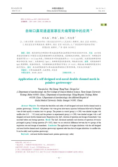
第24卷 第2期 中国内镜杂志 Vol. 24 No. 2 2018年2月 China Journal of Endoscopy Feb. 2018论 著收稿日期:2017-07-17*基金项目:广西教育厅科学技术项目(No :2013LX071)[通信作者] 刘志贵,E-mail :532769425@[专利] 口鼻双通道面罩(实用新型专利号ZL 201420418145.9)[作者简介] 第一作者2014年9月-2017年6月在广西桂林医学院就读全日制麻醉专业硕士研究生DOI: 10.3969/j.issn.1007-1989.2018.02.002文章编号: 1007-1989(2018)02-0006-04自制口鼻双通道面罩在无痛胃镜中的应用*刘天品1,钟海2,袁红2,刘志贵3[1.三峡大学第一临床医学院(湖北省宜昌市中心人民医院) 麻醉科,湖北 宜昌 443003; 2.湖北省宜昌市夷陵医院 麻醉科,湖北 宜昌 443100;3.广西省桂林市桂林医学院附属医院 麻醉科,广西 桂林 541001]摘要:目的 探讨该科自行研制的口鼻双通道面罩在无痛胃镜术中的安全性和可行性。
方法 400例患者接受丙泊酚与小剂量芬太尼复合静脉麻醉行无痛胃镜检查,患者随机分为两组,每组200例。
对照组采用普通鼻导管4.0~5.0 L/min 给氧;实验组采用口鼻双通道面罩4.0~5.0 L/min 给氧。
记录患者麻醉前和麻醉后呼吸次数(RR)、血氧饱和度(SpO 2)、麻醉药用量及检查时间,两组进行比较。
结果 对照组麻醉中SpO 2明显降低,检查时间延长,与实验组相比差异有统计学意义(P <0.05),两组RR 和麻醉药用量差异无统计学意义。
结论 在无痛胃镜检查中口鼻双通道面罩给氧优于鼻导管给氧,可安全应用及推广。
关键词: 口鼻双通道面罩;无痛胃镜;安全性中图分类号: R608;R614 文献标识码: AApplication of a self designed oral-nasal double channel mask in painless gastroscopy *Tian-pin Liu 1, Hai Zhong 2, Hong Yuan 2, Zhi-gui Liu3(1.Department of Anesthesiology, the First College of Clinical Medical Science, Three Gorges University,Yichang, Hubei 443003, China; 2.Department of Anesthesiology, Yiling Hospital, Yichang, Hubei443100, China; 3.Department of Anesthesiology, the Affiliated Hospital ofGuilin Medical University, Guilin, Guangxi 541001, China)Abstract: Objective To evaluate the feasibility and safety of self designed oral-nasal double channel mask in painless gastroscopy. Methods 400 patients who were given intravenous injection Sublimaze followed by Propofol were divided equally at random into two groups. The patients in control group (n = 200) were inhaled oxygen with snuffle tube (4.0 ~ 5.0 L/min) and the patients in experimental group (n = 200) were inhaled oxygen with a self designed oral-nasal double channel mask. Respiration rate, SpO 2, duration of operation and dosage of anaesthetic were recorded before and during operation. Result The SpO 2 decreased markedly and duration of operation obviously prolonged in group I during operation (P < 0.05), there was no statistical difference between the two groups of the respiration rate and dosage of anaesthetic. Conclusion The application of oxygen inhalation with the self designed oral-nasal double channel mask in painless gastroscopy appeared safer than that of oxygen inhalation via snuffle tube. It can be safely used in painless gastroscopy.Keywords: oral-nasal double channel mask; painless gastroscopy; safety第 2 期无痛胃镜技术在各大医院中主要采用门诊麻醉,门诊麻醉因为环境、设备以及人员的局限,意外发生率相对较高,具有高风险性和高挑战性[1]。

HEAVY DUTY SINGLE/DUAL BOTTLEWELDING CARTOWNER’S MANUAL5/2015Read carefully and understand all ASSEMBLY AND OPERATIONINSTRUCTIONS before operating. Failure to follow the safety rules and otherbasic safety precautions may result in serious personal injury.WARRANTYMETAL MAN WORK GEAR COEFFECTIVE JANUARY 1, 2013LIMITED WARRANTYThis warranty applies to the original purchaser and is subject to the terms and conditions listed below. This Limited Warranty is for new equipment sold after the above date, providing coverage for defects in material and workmanship at the time it is shipped from the factory.Limited to the warranty periods below, Metal Man Work Gear Co will repair or replace the item under warranty that fails due to defects in material and workmanship. Metal Man Work Gear must be notified within 30 days of the failure, so as to provide instructions on how to proceed with the repair of your welder and warranty claim processing. Warranty period begins at the time the welder is purchased from and Authorized Reseller of Metal Man Work Gear Co. products. Keep your receipt as proof of purchase.Warranty PeriodsLimited Warranty is divided into three categories. No Warranty, 90 days, 1 year and 3 year.No WarrantyNormal wear items, MIG gun parts (contact tips, nozzle, contact tip adapter, MIG gun liner), drive roll, electrode holder, ground clamps, Plasma torch parts (nozzle, electrode, diffuser, cover) are considered consumable items and are not covered under warranty.90 daysParts for Metal Man Work Gear welding carts and welding cabinets. This warranty covers the absence of or defective parts.1 yearParts and Labor on MIG gun parts (except those listed under normal wear items), cables, regulator, and plasma torch (except those listed under normal wear items). Any shipping related to warranty repair is the responsibility of the customer.1 year/3 yearPlease see your product information to determine if your product has a 1 year or 3 year warranty. This warranty covers parts and Labor on items such as: transformer, reactor, rectifier, solenoid valve, PC Board, switches, controls, gas valve, drive motor, drive system other than drive roll and any other component that requires the removal of the sheet metal to access. Any shipping related to warranty repair is the responsibility of the customer.Voiding WarrantyWarranty does not apply to: Shipping Damage, Misuse and abuse of the unit, alteration of the unit in any way.Warranty ClaimThis is a parts and labor warranty. Do not return your unit to the retailer you purchased it from. Retain your receipt in the case a warranty claim is needed. No warranty will be provided without the original receipt from an authorized reseller of Metal Man Work Gear Products. To make a warranty claim, call our welder help line at 888-762-4045, M-F 8:00 am to 5:00 PM Central time or email **********************.GENERAL SAFETY RULESWARNING: Read and understand all instructions. Failure to follow all instructions listed below may result in serious injury.CAUTION: Do not allow persons to operate or assemble this Flux Core 125until they have read this manual and have developed a thorough understanding of how the Flux Core 125works.WARNING:The warnings, cautions, and instructions discussed in this instruction manual cannot cover all possible conditions or situations that could occur. It must be understood by the operator that common sense and caution are factors which cannot be built into this product, but must be supplied by the operator.SAVE THESE INSTRUCTIONSIMPORTANT SAFETY CONSIDERATIONS1.1 Your Welding Environment-Keep the environment you will be welding in free from flammable materials.-Always keep a fire extinguisher accessible to your welding environment.-Always have a qualified person install and operate this equipment.-Make sure the area is clean, dry and ventilated. Do not operate the welder in humid, wet or poorly ventilated areas.-Always have your welder maintained by a qualified technician in accordance with local, state and national codes.-Always be aware of your work environment. Be sure to keep other people, especially children, away from you while welding.-Keep harmful arc rays shielded from the view of others.-Mount the welder on a secure bench or cart that will keep the welder secure and prevent it from tipping over or falling.1.2 Your Welder’s Condition-Check ground cable, power cord and welding cable to be sure the insulation is not damaged. Always replace or repair damaged components before using the welder.-Check all components to ensure they are clean and in good operating condition before use.1.3 Use of Your WelderDo not operate the welder if the output cable, electrode, torch, wire or wire feed system is wet. Do not immerse them in water. These components and the welder must be completely dry before attempting to use them.-Follow the instructions in this manual.-Keep welder in the off position when not in use.-Connect ground lead as close to the area being welded as possible to ensure a good ground.-Do not allow any body part to come in contact with the welding wire if you are in contact with the material being welded, ground or electrode from another welder.-Do not weld if you are in an awkward position. Always have a secure stance while welding to prevent accidents. Wear a safety harness if working above ground.-Do not drape cables over or around your body.-Wear a full coverage helmet with appropriate shade (see ANSI Z87.1 safety standard) and safety glasses while welding.-Wear proper gloves and protective clothing to prevent your skin from being exposed to hot metals, UV and IR rays.-Do not overuse or overheat your welder. Allow proper cooling time between duty cycles.-Keep hands and fingers away from moving parts and stay away from the drive rolls.-Do not point MIG gun at any body part of yourself or anyone else.-Always use this welder in the rated duty cycle to prevent excessive heat and failure.1.4 Specific Areas of Danger, Caution or WarningElectrical ShockElectric arc welders can produce a shock that can cause injury or death. Touchingelectrically live parts can cause fatal shocks and severe burns. While welding, all metal components connected to the wire are electrically hot. Poor ground connections are a hazard, so secure the ground lead before welding.-Wear dry protective apparel: coat, shirt, gloves and insulated footwear.-Insulate yourself from the work piece. Avoid contacting the work piece or ground.- Do not attempt to repair or maintain the welder while the power is on.-Inspect all cables and cords for any exposed wire and replace immediately if found.-Use only recommended replacement cables and cords.-Always attach ground clamp to the work piece or work table as close to the weld area as possible. -Do not touch the welding wire and the ground or grounded work piece at the same time.-Do not use a welder to thaw frozen pipes.Fumes and Gases-Fumes emitted from the welding process displace clean air and can result in injury or death.-Do not breathe in fumes emitted by the welding process. Make sure your breathing air is clean and safe.-Work only in a well-ventilated area or use a ventilation device to remove welding fumes from the environment where you will be working.-Do not weld on coated materials (galvanized, cadmium plated or containing zinc, mercury or barium). They will emit harmful fumes that are dangerous to breathe. If necessary use a ventilator, respirator with air supply or remove the coating from the material in the weld area.-The fumes emitted from some metals when heated are extremely toxic. Refer to the material safety data sheet for the manufacturer’s instructions.-Do not weld near materials that will emit toxic fumes when heated. Vapors from cleaners, sprays and degreasers can be highly toxic when heated.UV and IR Arc RaysThe welding arc produces ultraviolet (UV) and infrared (IR) rays that can cause injury toyour eyes and skin. Do not look at the welding arc without proper eye protection.-Always use a helmet that covers your full face from the neck to top of head and to the back of each ear.-Use a lens that meets ANSI standards and safety glasses. For welders under 160 Amps output, use a shade 10 lens; for above 160 Amps, use a shade 12. Refer to the ANSI standard Z87.1 for more information.-Cover all bare skin areas exposed to the arc with protective clothing and shoes. Flame-retardant cloth or leather shirts, coats, pants or coveralls are available for protection.-Use screens or other barriers to protect other people from the arc rays emitted from your welding. -Warn people in your welding area when you are going to strike an arc so they can protect themselves.Fire HazardsDo not weld on containers or pipes that contain or have had flammable, gaseous or liquid combustibles in them. Welding creates sparks and heat that can ignite flammable and explosive materials.-Do not operate any electric arc welder in areas where flammable or explosive materials are present.-Remove all flammable materials within 35 feet of the welding arc. If removal is not possible, tightly cover them with fireproof covers.-Take precautions to ensure that flying sparks do not cause fires or explosions in hidden areas, cracks or areas you cannot see.-Keep a fire extinguisher close in the case of fire.-Wear garments that are oil-free with no pockets or cuffs that will collect sparks.-Do not have on your person any items that are combustible, such as lighters or matches.-Keep work lead connected as close to the weld area as possible to prevent any unknown, unintended paths of electrical current from causing electrical shock and fire hazards.-To prevent any unintended arcs, cut wire back to ¼" stick out after welding.Hot MaterialsWelded materials are hot and can cause severe burns if handled improperly.-Do not touch welded materials with bare hands.-Do not touch MIG gun nozzle after welding until it has had time to cool down.Sparks/Flying DebrisWelding creates hot sparks that can cause injury. Chipping slag off welds creates flying debris.-Wear protective apparel at all times: ANSI-approved safety glasses or shield, welder’s hat and ear plugs to keep sparks out of ears and hair.Electromagnetic Field-Electromagnetic fields can interfere with various electrical and electronic devices such as pacemakers.-Consult your doctor before using any electric arc welder or cutting device-Keep people with pacemakers away from your welding area when welding.-Do not wrap cable around your body while welding.-Wrap MIG gun and ground cable together whenever possible.-Keep MIG gun and ground cables on the same side of your body.Shielding Gas Cylinders Can ExplodeHigh pressure cylinders can explode if damaged, so treat them carefully.-Never expose cylinders to high heat, sparks, open flames, mechanical shocks or arcs.-Do not touch cylinder with MIG gun.-Do not weld on the cylinder-Always secure cylinder upright to a cart or stationary object.-Keep cylinders away from welding or electrical circuits.-Use the proper regulators, gas hose and fittings for the specific application.-Do not look into the valve when opening it.-Use protective cylinder cap whenever possible1.5 Proper Care, Maintenance and Repair-Always have power disconnected when working on internal components.- Do not touch or handle PC board without being properly grounded with a wrist strap. Put PC board in static proof bag to move or ship.-Do not put hands or fingers near moving parts such as drive rolls of fanUSE AND CARE∙Do not modify this unit in any way. Unauthorized modification may impair the function and/or safety and could affect the life of the equipment. There are specific applications for which this unit was designed.∙Always check of damaged or worn out parts before using this unit. Broken parts will affect the operation. Replace or repair damaged or worn parts immediately.∙Store idle. When this unit is not in use, store it in a secure place out of the reach of children.Inspect it for good working condition prior to storage and before re-use. SPECIFICATIONSDESCRIPTIONThe METAL MAN Heavy Duty Single/Dual Bottle Welding Cart is designed for multiple uses as a welding cart. First it can be used to hold portable wire welders, plasma cutters and TIG welders along with the bottle of shielding gas needed for that application. Its unique Cylinder rack allows you to configure it to carry one bottle of gas up to 10 inches in diameter and up to 300 cu. Ft.; or two separate bottles of gas up to 7-1/2 inches in diameter or 150 cu. Ft each.The second use for this welding cart could be to hold two separate welders or a welder and a plasma cutter. The bottom shelf has an 18 inch clearance, giving able space to store one unit on the top shelf and one unit on the bottom shelf. Two units, may require two bottles of shielding gas. Simply configure the cylinder rack to the dual bottle cylinder configuration.A third use for the Heavy Duty Single/Dual Bottle Welding Cart is as a power source and feeder cart. The bottom shelf has an 18 inch clearance, giving able space to store a smaller, inverter-based welding power source on the bottom shelf. The top shelf has ample space to fit a wire feeder. In addition, the top of the cylinder securement rack can be removed to accommodate the wire feeder spool holder and a large spool of wire.This cart’s top shelf is approximately 25inches from the floor, putting the machine controls at a comfortable operating height. A 20 inch wide base, 8 inch rear wheels, locking front casters, and fold down handle make this cart stable and easy to maneuver. This unit also has two sets of cable wraps to organize all the welding cables safely.CableWrapsCylinderRack8 InchWheelsFold DownHandleBottomShelfLockableFront CasterTYPICAL APPLICATIONS1.1 Portable Welder Cart1.2 Portable Welder Plus Plasma Cutter Cart (Dual Welder)1.3 Inverter Power Source & Feeder CartPortable with Single or Dual Cylinders Portable with Cylinder Rack Removed1.4 Single Cylinder Securement Dual Cylinder SecurementASSEMBLY1. On a flat surface, stand the two frame pieces up on their long side.2. Lay the bottom shelf lip up on top of the two frame pieces.3. Line up the pre-drilled holes in the bottom shelf with the pre-drilled holes in the long side ofone of the frame pieces.4. From the bottom of one frame piece, insert the threaded shaft of one caster, through thepre-drilled hole of the frame, then up through the pre-drilled hole of the bottom shelf.5. Secure caster with a flat washer, lock washer and nut.6. Repeat steps 3 through 5 using the other frame piece.7. Use 8 of the self-tapping screws to secure the bottom shelf to the frame using the pre-drilledholes in the bottom shelf and frame.8. Slide the axle through the pre-drilled axle clip on the bottom of the frame.9. Slide a wheel on each side.10. Secure each wheel with a flat washer and cotter pin.11. Find the top shelf.12. Align the pre-drilled holes in the top shelf with the pre-drilled holes in the frame pieces. Use4 self-tapping screws to secure the top shelf to the frame.13. Located the pre-drilled hole on the front left frame just under the top shelf. From the outsideof the frame, insert one of the clevis pins through the pre-drilled hole in the frame. Slide alatch and then a flat washer onto the open end of the clevis pin. Secure both with a cotterpin.14. Repeat the last step for the right side frame.15. Locate the other pre-drilled hole on the front left frame. From the outside of the frame, insertone of the clevis pins through the pre-drilled hole in the frame. Slide the pre-drilled hole inone end of the handle onto the clevis pin. Add a flat washer and secure with a cotter pin.16. Repeat the last step for the right side frame.17. Find one of the cable holders. Make note of the two pre-drilled mounting holes in the leftfront lip of the top shelf. Position the cable holder so the pre-drilled mounting holes in thecable holder align with the pre-drilled mounting holes in the lip of the top shelf. Position this cable holder so the opening goes to the front of the cart. Using a hex bolt, slide on a flatwasher and slide the bolt through the pre-drilled holes in the cable holder and into thematching pre-drilled holes in the top shelf. Secure with a flat washer, lock washer and Hex Nut. Repeat for the other mounting hole.18. Still on the left side of the cart, find the two pre-drilled mounting holes on the left back lip ofthe top shelf. Position the cable holder so the pre-drilled mounting holes in the cable holder align with the pre-drilled mounting holes in the lip of the top shelf. Position this cable holder so the opening goes to the back of the cart. Using a hex bolt, slide on a flat washer andslide the bolt through the pre-drilled holes in the cable holder and into the matchingpre-drilled holes in the top shelf. Secure with a flat washer, lock washer and Hex Nut.Repeat for the other mounting hole.19. Repeat the last two steps for the right side of the cart.20. Find one of the Cylinder Support Vertical Tubes. On the back left side of the cart frame,slide the small end of the Cylinder Support Vertical Tube into the square opening in the cart frame. Make certain the pre-drilled mounting holes in the Cylinder Support Vertical Tubematch up with the pre-drilled mounting holes in the square opening of the cart frame. Usinga long hex bolt, slide on a flat washer and slide the bolt through the pre-drilled holes in thecart frame and into the matching pre-drilled holes in the Cylinder Support Vertical Tubes.Secure with a flat washer, lock washer and Hex Nut. Repeat for the other mounting hole.Then repeat for the other side of the frame.21. Locate one of the Cylinder Support Brackets. After reviewing the Cylinder Support Bracket,you will see that it can be positioned and set up for a single cylinder or two cylinders.Choose the cylinder orientation you want and align the pre-drilled mounting holes with the pre-drilled mounting holes in the Cylinder Support Vertical Tubes. Using a long hex bolt, slide on a flat washer and slide the bolt through the pre-drilled holes in the Cylinder Support Vertical Tubes and into the matching pre-drilled holes in the Cylinder Support Bracket.Secure with a flat washer, lock washer and Hex Nut. Repeat for the other mounting hole.Then repeat for the other side of the Cylinder Support Vertical Tubes.22. Using the last Cylinder Support Bracket, find the matching mounting holes on the back ofthe two frame pieces. Using a long hex bolt, slide on a flat washer and slide the bolt through the pre-drilled holes in the cart frame and into the matching pre-drilled holes in the Cylinder Support Bracket. Secure with a flat washer, lock washer and Hex Nut. Repeat for the other mounting hole. Then repeat for the other side of the frame.23. Put the Gas Cylinder Retaining Chain in the open slots in the Cylinder Support Bracket. DIAGRAM & PARTS LISTFor replacement parts or technical questions, please contact our welder help line at 1-888-762-4045.Distributed byMETAL MAN WORK GEAR COMPANY1760 PROSPECT CT #120APPLETON WI 54914Made in China。

NORMEINTERNATIONALECEI IEC INTERNATIONALSTANDARD 61854Première éditionFirst edition1998-09Lignes aériennes –Exigences et essais applicables aux entretoisesOverhead lines –Requirements and tests for spacersCommission Electrotechnique InternationaleInternational Electrotechnical Commission Pour prix, voir catalogue en vigueurFor price, see current catalogue© IEC 1998 Droits de reproduction réservés Copyright - all rights reservedAucune partie de cette publication ne peut être reproduite niutilisée sous quelque forme que ce soit et par aucunprocédé, électronique ou mécanique, y compris la photo-copie et les microfilms, sans l'accord écrit de l'éditeur.No part of this publication may be reproduced or utilized in any form or by any means, electronic or mechanical,including photocopying and microfilm, without permission in writing from the publisher.International Electrotechnical Commission 3, rue de Varembé Geneva, SwitzerlandTelefax: +41 22 919 0300e-mail: inmail@iec.ch IEC web site http: //www.iec.chCODE PRIX PRICE CODE X– 2 –61854 © CEI:1998SOMMAIREPages AVANT-PROPOS (6)Articles1Domaine d'application (8)2Références normatives (8)3Définitions (12)4Exigences générales (12)4.1Conception (12)4.2Matériaux (14)4.2.1Généralités (14)4.2.2Matériaux non métalliques (14)4.3Masse, dimensions et tolérances (14)4.4Protection contre la corrosion (14)4.5Aspect et finition de fabrication (14)4.6Marquage (14)4.7Consignes d'installation (14)5Assurance de la qualité (16)6Classification des essais (16)6.1Essais de type (16)6.1.1Généralités (16)6.1.2Application (16)6.2Essais sur échantillon (16)6.2.1Généralités (16)6.2.2Application (16)6.2.3Echantillonnage et critères de réception (18)6.3Essais individuels de série (18)6.3.1Généralités (18)6.3.2Application et critères de réception (18)6.4Tableau des essais à effectuer (18)7Méthodes d'essai (22)7.1Contrôle visuel (22)7.2Vérification des dimensions, des matériaux et de la masse (22)7.3Essai de protection contre la corrosion (22)7.3.1Composants revêtus par galvanisation à chaud (autres queles fils d'acier galvanisés toronnés) (22)7.3.2Produits en fer protégés contre la corrosion par des méthodes autresque la galvanisation à chaud (24)7.3.3Fils d'acier galvanisé toronnés (24)7.3.4Corrosion causée par des composants non métalliques (24)7.4Essais non destructifs (24)61854 © IEC:1998– 3 –CONTENTSPage FOREWORD (7)Clause1Scope (9)2Normative references (9)3Definitions (13)4General requirements (13)4.1Design (13)4.2Materials (15)4.2.1General (15)4.2.2Non-metallic materials (15)4.3Mass, dimensions and tolerances (15)4.4Protection against corrosion (15)4.5Manufacturing appearance and finish (15)4.6Marking (15)4.7Installation instructions (15)5Quality assurance (17)6Classification of tests (17)6.1Type tests (17)6.1.1General (17)6.1.2Application (17)6.2Sample tests (17)6.2.1General (17)6.2.2Application (17)6.2.3Sampling and acceptance criteria (19)6.3Routine tests (19)6.3.1General (19)6.3.2Application and acceptance criteria (19)6.4Table of tests to be applied (19)7Test methods (23)7.1Visual examination (23)7.2Verification of dimensions, materials and mass (23)7.3Corrosion protection test (23)7.3.1Hot dip galvanized components (other than stranded galvanizedsteel wires) (23)7.3.2Ferrous components protected from corrosion by methods other thanhot dip galvanizing (25)7.3.3Stranded galvanized steel wires (25)7.3.4Corrosion caused by non-metallic components (25)7.4Non-destructive tests (25)– 4 –61854 © CEI:1998 Articles Pages7.5Essais mécaniques (26)7.5.1Essais de glissement des pinces (26)7.5.1.1Essai de glissement longitudinal (26)7.5.1.2Essai de glissement en torsion (28)7.5.2Essai de boulon fusible (28)7.5.3Essai de serrage des boulons de pince (30)7.5.4Essais de courant de court-circuit simulé et essais de compressionet de traction (30)7.5.4.1Essai de courant de court-circuit simulé (30)7.5.4.2Essai de compression et de traction (32)7.5.5Caractérisation des propriétés élastiques et d'amortissement (32)7.5.6Essais de flexibilité (38)7.5.7Essais de fatigue (38)7.5.7.1Généralités (38)7.5.7.2Oscillation de sous-portée (40)7.5.7.3Vibrations éoliennes (40)7.6Essais de caractérisation des élastomères (42)7.6.1Généralités (42)7.6.2Essais (42)7.6.3Essai de résistance à l'ozone (46)7.7Essais électriques (46)7.7.1Essais d'effet couronne et de tension de perturbations radioélectriques..467.7.2Essai de résistance électrique (46)7.8Vérification du comportement vibratoire du système faisceau/entretoise (48)Annexe A (normative) Informations techniques minimales à convenirentre acheteur et fournisseur (64)Annexe B (informative) Forces de compression dans l'essai de courantde court-circuit simulé (66)Annexe C (informative) Caractérisation des propriétés élastiques et d'amortissementMéthode de détermination de la rigidité et de l'amortissement (70)Annexe D (informative) Contrôle du comportement vibratoire du systèmefaisceau/entretoise (74)Bibliographie (80)Figures (50)Tableau 1 – Essais sur les entretoises (20)Tableau 2 – Essais sur les élastomères (44)61854 © IEC:1998– 5 –Clause Page7.5Mechanical tests (27)7.5.1Clamp slip tests (27)7.5.1.1Longitudinal slip test (27)7.5.1.2Torsional slip test (29)7.5.2Breakaway bolt test (29)7.5.3Clamp bolt tightening test (31)7.5.4Simulated short-circuit current test and compression and tension tests (31)7.5.4.1Simulated short-circuit current test (31)7.5.4.2Compression and tension test (33)7.5.5Characterisation of the elastic and damping properties (33)7.5.6Flexibility tests (39)7.5.7Fatigue tests (39)7.5.7.1General (39)7.5.7.2Subspan oscillation (41)7.5.7.3Aeolian vibration (41)7.6Tests to characterise elastomers (43)7.6.1General (43)7.6.2Tests (43)7.6.3Ozone resistance test (47)7.7Electrical tests (47)7.7.1Corona and radio interference voltage (RIV) tests (47)7.7.2Electrical resistance test (47)7.8Verification of vibration behaviour of the bundle-spacer system (49)Annex A (normative) Minimum technical details to be agreed betweenpurchaser and supplier (65)Annex B (informative) Compressive forces in the simulated short-circuit current test (67)Annex C (informative) Characterisation of the elastic and damping propertiesStiffness-Damping Method (71)Annex D (informative) Verification of vibration behaviour of the bundle/spacer system (75)Bibliography (81)Figures (51)Table 1 – Tests on spacers (21)Table 2 – Tests on elastomers (45)– 6 –61854 © CEI:1998 COMMISSION ÉLECTROTECHNIQUE INTERNATIONALE––––––––––LIGNES AÉRIENNES –EXIGENCES ET ESSAIS APPLICABLES AUX ENTRETOISESAVANT-PROPOS1)La CEI (Commission Electrotechnique Internationale) est une organisation mondiale de normalisation composéede l'ensemble des comités électrotechniques nationaux (Comités nationaux de la CEI). La CEI a pour objet de favoriser la coopération internationale pour toutes les questions de normalisation dans les domaines de l'électricité et de l'électronique. A cet effet, la CEI, entre autres activités, publie des Normes internationales.Leur élaboration est confiée à des comités d'études, aux travaux desquels tout Comité national intéressé par le sujet traité peut participer. Les organisations internationales, gouvernementales et non gouvernementales, en liaison avec la CEI, participent également aux travaux. La CEI collabore étroitement avec l'Organisation Internationale de Normalisation (ISO), selon des conditions fixées par accord entre les deux organisations.2)Les décisions ou accords officiels de la CEI concernant les questions techniques représentent, dans la mesuredu possible un accord international sur les sujets étudiés, étant donné que les Comités nationaux intéressés sont représentés dans chaque comité d’études.3)Les documents produits se présentent sous la forme de recommandations internationales. Ils sont publiéscomme normes, rapports techniques ou guides et agréés comme tels par les Comités nationaux.4)Dans le but d'encourager l'unification internationale, les Comités nationaux de la CEI s'engagent à appliquer defaçon transparente, dans toute la mesure possible, les Normes internationales de la CEI dans leurs normes nationales et régionales. Toute divergence entre la norme de la CEI et la norme nationale ou régionale correspondante doit être indiquée en termes clairs dans cette dernière.5)La CEI n’a fixé aucune procédure concernant le marquage comme indication d’approbation et sa responsabilitén’est pas engagée quand un matériel est déclaré conforme à l’une de ses normes.6) L’attention est attirée sur le fait que certains des éléments de la présente Norme internationale peuvent fairel’objet de droits de propriété intellectuelle ou de droits analogues. La CEI ne saurait être tenue pour responsable de ne pas avoir identifié de tels droits de propriété et de ne pas avoir signalé leur existence.La Norme internationale CEI 61854 a été établie par le comité d'études 11 de la CEI: Lignes aériennes.Le texte de cette norme est issu des documents suivants:FDIS Rapport de vote11/141/FDIS11/143/RVDLe rapport de vote indiqué dans le tableau ci-dessus donne toute information sur le vote ayant abouti à l'approbation de cette norme.L’annexe A fait partie intégrante de cette norme.Les annexes B, C et D sont données uniquement à titre d’information.61854 © IEC:1998– 7 –INTERNATIONAL ELECTROTECHNICAL COMMISSION––––––––––OVERHEAD LINES –REQUIREMENTS AND TESTS FOR SPACERSFOREWORD1)The IEC (International Electrotechnical Commission) is a worldwide organization for standardization comprisingall national electrotechnical committees (IEC National Committees). The object of the IEC is to promote international co-operation on all questions concerning standardization in the electrical and electronic fields. To this end and in addition to other activities, the IEC publishes International Standards. Their preparation is entrusted to technical committees; any IEC National Committee interested in the subject dealt with may participate in this preparatory work. International, governmental and non-governmental organizations liaising with the IEC also participate in this preparation. The IEC collaborates closely with the International Organization for Standardization (ISO) in accordance with conditions determined by agreement between the two organizations.2)The formal decisions or agreements of the IEC on technical matters express, as nearly as possible, aninternational consensus of opinion on the relevant subjects since each technical committee has representation from all interested National Committees.3)The documents produced have the form of recommendations for international use and are published in the formof standards, technical reports or guides and they are accepted by the National Committees in that sense.4)In order to promote international unification, IEC National Committees undertake to apply IEC InternationalStandards transparently to the maximum extent possible in their national and regional standards. Any divergence between the IEC Standard and the corresponding national or regional standard shall be clearly indicated in the latter.5)The IEC provides no marking procedure to indicate its approval and cannot be rendered responsible for anyequipment declared to be in conformity with one of its standards.6) Attention is drawn to the possibility that some of the elements of this International Standard may be the subjectof patent rights. The IEC shall not be held responsible for identifying any or all such patent rights. International Standard IEC 61854 has been prepared by IEC technical committee 11: Overhead lines.The text of this standard is based on the following documents:FDIS Report on voting11/141/FDIS11/143/RVDFull information on the voting for the approval of this standard can be found in the report on voting indicated in the above table.Annex A forms an integral part of this standard.Annexes B, C and D are for information only.– 8 –61854 © CEI:1998LIGNES AÉRIENNES –EXIGENCES ET ESSAIS APPLICABLES AUX ENTRETOISES1 Domaine d'applicationLa présente Norme internationale s'applique aux entretoises destinées aux faisceaux de conducteurs de lignes aériennes. Elle recouvre les entretoises rigides, les entretoises flexibles et les entretoises amortissantes.Elle ne s'applique pas aux espaceurs, aux écarteurs à anneaux et aux entretoises de mise à la terre.NOTE – La présente norme est applicable aux pratiques de conception de lignes et aux entretoises les plus couramment utilisées au moment de sa rédaction. Il peut exister d'autres entretoises auxquelles les essais spécifiques décrits dans la présente norme ne s'appliquent pas.Dans de nombreux cas, les procédures d'essai et les valeurs d'essai sont convenues entre l'acheteur et le fournisseur et sont énoncées dans le contrat d'approvisionnement. L'acheteur est le mieux à même d'évaluer les conditions de service prévues, qu'il convient d'utiliser comme base à la définition de la sévérité des essais.La liste des informations techniques minimales à convenir entre acheteur et fournisseur est fournie en annexe A.2 Références normativesLes documents normatifs suivants contiennent des dispositions qui, par suite de la référence qui y est faite, constituent des dispositions valables pour la présente Norme internationale. Au moment de la publication, les éditions indiquées étaient en vigueur. Tout document normatif est sujet à révision et les parties prenantes aux accords fondés sur la présente Norme internationale sont invitées à rechercher la possibilité d'appliquer les éditions les plus récentes des documents normatifs indiqués ci-après. Les membres de la CEI et de l'ISO possèdent le registre des Normes internationales en vigueur.CEI 60050(466):1990, Vocabulaire Electrotechnique International (VEI) – Chapitre 466: Lignes aériennesCEI 61284:1997, Lignes aériennes – Exigences et essais pour le matériel d'équipementCEI 60888:1987, Fils en acier zingué pour conducteurs câblésISO 34-1:1994, Caoutchouc vulcanisé ou thermoplastique – Détermination de la résistance au déchirement – Partie 1: Eprouvettes pantalon, angulaire et croissantISO 34-2:1996, Caoutchouc vulcanisé ou thermoplastique – Détermination de la résistance au déchirement – Partie 2: Petites éprouvettes (éprouvettes de Delft)ISO 37:1994, Caoutchouc vulcanisé ou thermoplastique – Détermination des caractéristiques de contrainte-déformation en traction61854 © IEC:1998– 9 –OVERHEAD LINES –REQUIREMENTS AND TESTS FOR SPACERS1 ScopeThis International Standard applies to spacers for conductor bundles of overhead lines. It covers rigid spacers, flexible spacers and spacer dampers.It does not apply to interphase spacers, hoop spacers and bonding spacers.NOTE – This standard is written to cover the line design practices and spacers most commonly used at the time of writing. There may be other spacers available for which the specific tests reported in this standard may not be applicable.In many cases, test procedures and test values are left to agreement between purchaser and supplier and are stated in the procurement contract. The purchaser is best able to evaluate the intended service conditions, which should be the basis for establishing the test severity.In annex A, the minimum technical details to be agreed between purchaser and supplier are listed.2 Normative referencesThe following normative documents contain provisions which, through reference in this text, constitute provisions of this International Standard. At the time of publication of this standard, the editions indicated were valid. All normative documents are subject to revision, and parties to agreements based on this International Standard are encouraged to investigate the possibility of applying the most recent editions of the normative documents indicated below. Members of IEC and ISO maintain registers of currently valid International Standards.IEC 60050(466):1990, International Electrotechnical vocabulary (IEV) – Chapter 466: Overhead linesIEC 61284:1997, Overhead lines – Requirements and tests for fittingsIEC 60888:1987, Zinc-coated steel wires for stranded conductorsISO 34-1:1994, Rubber, vulcanized or thermoplastic – Determination of tear strength – Part 1: Trouser, angle and crescent test piecesISO 34-2:1996, Rubber, vulcanized or thermoplastic – Determination of tear strength – Part 2: Small (Delft) test piecesISO 37:1994, Rubber, vulcanized or thermoplastic – Determination of tensile stress-strain properties– 10 –61854 © CEI:1998 ISO 188:1982, Caoutchouc vulcanisé – Essais de résistance au vieillissement accéléré ou à la chaleurISO 812:1991, Caoutchouc vulcanisé – Détermination de la fragilité à basse températureISO 815:1991, Caoutchouc vulcanisé ou thermoplastique – Détermination de la déformation rémanente après compression aux températures ambiantes, élevées ou bassesISO 868:1985, Plastiques et ébonite – Détermination de la dureté par pénétration au moyen d'un duromètre (dureté Shore)ISO 1183:1987, Plastiques – Méthodes pour déterminer la masse volumique et la densitérelative des plastiques non alvéolairesISO 1431-1:1989, Caoutchouc vulcanisé ou thermoplastique – Résistance au craquelage par l'ozone – Partie 1: Essai sous allongement statiqueISO 1461,— Revêtements de galvanisation à chaud sur produits finis ferreux – Spécifications1) ISO 1817:1985, Caoutchouc vulcanisé – Détermination de l'action des liquidesISO 2781:1988, Caoutchouc vulcanisé – Détermination de la masse volumiqueISO 2859-1:1989, Règles d'échantillonnage pour les contrôles par attributs – Partie 1: Plans d'échantillonnage pour les contrôles lot par lot, indexés d'après le niveau de qualité acceptable (NQA)ISO 2859-2:1985, Règles d'échantillonnage pour les contrôles par attributs – Partie 2: Plans d'échantillonnage pour les contrôles de lots isolés, indexés d'après la qualité limite (QL)ISO 2921:1982, Caoutchouc vulcanisé – Détermination des caractéristiques à basse température – Méthode température-retrait (essai TR)ISO 3417:1991, Caoutchouc – Détermination des caractéristiques de vulcanisation à l'aide du rhéomètre à disque oscillantISO 3951:1989, Règles et tables d'échantillonnage pour les contrôles par mesures des pourcentages de non conformesISO 4649:1985, Caoutchouc – Détermination de la résistance à l'abrasion à l'aide d'un dispositif à tambour tournantISO 4662:1986, Caoutchouc – Détermination de la résilience de rebondissement des vulcanisats––––––––––1) A publierThis is a preview - click here to buy the full publication61854 © IEC:1998– 11 –ISO 188:1982, Rubber, vulcanized – Accelerated ageing or heat-resistance testsISO 812:1991, Rubber, vulcanized – Determination of low temperature brittlenessISO 815:1991, Rubber, vulcanized or thermoplastic – Determination of compression set at ambient, elevated or low temperaturesISO 868:1985, Plastics and ebonite – Determination of indentation hardness by means of a durometer (Shore hardness)ISO 1183:1987, Plastics – Methods for determining the density and relative density of non-cellular plasticsISO 1431-1:1989, Rubber, vulcanized or thermoplastic – Resistance to ozone cracking –Part 1: static strain testISO 1461, — Hot dip galvanized coatings on fabricated ferrous products – Specifications1)ISO 1817:1985, Rubber, vulcanized – Determination of the effect of liquidsISO 2781:1988, Rubber, vulcanized – Determination of densityISO 2859-1:1989, Sampling procedures for inspection by attributes – Part 1: Sampling plans indexed by acceptable quality level (AQL) for lot-by-lot inspectionISO 2859-2:1985, Sampling procedures for inspection by attributes – Part 2: Sampling plans indexed by limiting quality level (LQ) for isolated lot inspectionISO 2921:1982, Rubber, vulcanized – Determination of low temperature characteristics –Temperature-retraction procedure (TR test)ISO 3417:1991, Rubber – Measurement of vulcanization characteristics with the oscillating disc curemeterISO 3951:1989, Sampling procedures and charts for inspection by variables for percent nonconformingISO 4649:1985, Rubber – Determination of abrasion resistance using a rotating cylindrical drum deviceISO 4662:1986, Rubber – Determination of rebound resilience of vulcanizates–––––––––1) To be published.。
flammability certificationsIntroductionFlammability certifications play a crucial role in ensuring the safety of products. These certifications are used to assess the fire resistance and potential fire hazards of various materials and products. In this article, we will explore what flammability certifications are, why they are important, and the process involved in obtaining these certifications.Importance of Flammability CertificationsFlammability certifications are essential for several reasons. Firstly, they help protect public health and safety by ensuring that products meet certain fire safety standards. This is particularly important for products that are used in environments where fire hazards are prevalent, such as in buildings, vehicles, and electrical appliances.Secondly, flammability certifications provide a level of assurance to consumers that the products they purchase have been tested for fire safety. Being able to identify certified products allows consumers to make informed decisions and choose items that meet the required safety standards.Lastly, flammability certifications are necessary for compliance with legal and regulatory requirements. Many countries have specific regulations on the fire safety standards that products must meet. Obtaining the relevant certifications is often a legal requirement for manufacturers and importers before they can distribute and sell their products in the market.Types of Flammability CertificationsThere are various types of flammability certifications that are applicable to different industries and products. Some of the most common certifications include:1. UL 94UL 94 is a flammability standard primarily used for testing the flammability of plastic materials. It classifies materials intodifferent categories based on their burning behavior, such as V-0 (most flame-resistant), V-1, V-2, HB, and so on. Manufacturers and regulatory agencies often look for UL 94 certification to ensure the fire resistance of plastic components.2. NFPA 701NFPA 701 is a standard used for testing the flammability of textiles and fabrics. It provides a framework for evaluating the ignition resistance and flame spread characteristics of materials used in curtains, draperies, upholstery, and other related products. This certification is commonly required for textiles used in public spaces, such as hotels and theaters.3. FM ApprovalFM Approval is a certification provided by FM Global, an insurance company specializing in loss prevention services. It focuses on assessing the fire resistance of various products and systems, including roofing materials, electrical equipment, and industrial machinery. FM Approval ensures that products meet rigorous fire safety standards and are suitable for commercial and industrial applications.4. IEC 60695IEC 60695 is an international standard that specifies test methods for assessing the fire hazard of electrical and electronic products. It includes various tests, such as the glow-wire test, needle-flame test, and tracking test, to evaluate the fire resistance and safety of these products. Compliance with IEC 60695 is often a requirement forelectrical equipment manufacturers.Process of Obtaining Flammability CertificationsObtaining flammability certifications involves several steps and testing procedures. While the exact process may vary depending on the certification body and the specific certification being sought, the following general steps are typically involved:1.Application: The manufacturer or importer applies to a designatedcertification body or testing laboratory for the flammabilitycertification. The application includes providing relevant product information, such as material composition, intended use, andexisting test reports if available.2.Testing: The certification body or laboratory conducts a seriesof tests to evaluat e the product’s fire resistance andflammability characteristics. The specific tests depend on thetype of certification being sought.3.Evaluation: The test results are evaluated by experts todetermine whether the product meets the required flammabilitystandards and criteria. This evaluation may include a thoroughanalysis of the test data, physical inspections of the product,and reviews of supporting documentation.4.Certification Issuance: If the product successfully meets theflammability requirements, the certification body issues theflammability certification. This certification will typicallyinclude details such as the name of the manufacturer, the product description, and any limitations or conditions associated with the certification.5.Surveillance and Renewal: Flammability certifications often havea validity period. During this period, the certification body mayconduct regular surveillance tests and inspections to ensureongoing compliance. Manufacturers may also need to renew theircertifications periodically.ConclusionFlammability certifications are crucial for ensuring the safety and fire resistance of various products. They provide assurance to consumers, meet legal and regulatory requirements, and help protect public health and welfare. By understanding the importance of flammabilitycertifications and the process involved in obtaining them, manufacturers and consumers can make well-informed decisions about the safety of products they produce, purchase, or use.。


巴斯夫公司安全手册HSE Page1我们相信实现安全、健康、环保是我们的思维模式,这种思维模式贯穿于我们的日常工作中。
虽然我们主订有制度并有相关的监督和检查,但是确保安全最有效的部分是您的积极参与和良好示范。
We believe that achievement in Safety,health and Environmental performance is a mindset, which begins daily and to be carried out through everything we do.There are procedures and there will be monitoring,auditing but the most effective component for ensuring Safety is your active attention and good example.由于安全必然会影响到项目的目标,所以每项任务都必须通过有效的计划、交流、协调、合作来安全地执行。
每位员工都要对自己的行为负责,同时监督安全制度在工作场所的执行情况。
任何危及安全的行为或状况都需要马上向您的主管报告。
一个安全的工作场所是每个人的目标。
我们殷切期望每个人都尽职尽责为自己和他人创造一个安全的工作场所。
As safety will invariably affect the project objective,it is imperative that every assigned task must be executed safety through effective planning,communication,co-ordination and co-operation.All members are accountable for his/her own behaviors and must observe the safety rules and instructions applicable to the workplace.Any unsafe act or condition should be reported promptly to your immediate supervisor.A safe place to work is the goal of everyone.You are urged to do your part in making the workplace as a safe area for yourself and others.请仔细阅读本手册中的规定。
米索前列醇与催产素在晚期妊娠引产中的应用分析胡珊;胡燕【摘要】目的探讨米索前列醇与催产素在晚期妊娠引产中的应用.方法选择300例初产妇为观察病例,随机分为两组,分别给予舌下含服米索前列醇与静滴催产素引产,通过对比宫颈成熟度、引产效果、分娩结局、新生儿情况等方面数据进行统计分析.结果米索前列醇组宫颈评分增加、引产有效率高、临产时间短、总产程短、剖宫产率低,但发生急产3例,新生儿情况两组无差异.结论妊娠晚期孕妇舌下含服小剂量米索前列醇促进宫颈成熟及引产,在规范用药指征、合理掌握禁忌证及方法,并加强母婴监护的前提下,其效果显著优于催产素,并且安全可靠.%Objective To analyze the application of misoprostol and oxytocin in induced labor of late pregnancy. Methods 300 cases of primipara were randomly divided into two groups. One group was given misoprostol by sublingual administrating and the another group was given oxytocin by intravenous drip. The data in aspects of the cervical maturity, effect of induced labor, delivery outcome and newborn status were compared for statistical analysis. Results In the misoprostol group, the cervical maturity scores were increased with high effective rate of induced labor, short parturient time, short total stage of labor and low cesarean section rate , but precipitate labor occurred in 3 cases. The newborn status had no difference between the two groups. Conclusion Sublingual small dose of misoprostol in late pregnancy promotes the cervical mutarity and induced labor. In the premise of standardized medication indication, contraindication and method, at the same time strengthening the maternaland newborn monitoring, its effect is superior to oxytoin with safety and reliability.【期刊名称】《重庆医学》【年(卷),期】2012(041)017【总页数】3页(P1687-1688,1692)【关键词】米索前列醇;催产素;晚期妊娠;引产【作者】胡珊;胡燕【作者单位】武警重庆总队医院妇产科,重庆,400061;武警重庆总队医院妇产科,重庆,400061【正文语种】中文由于经济的原因,中国目前在常规引产手段中催产素的运用仍是首选,但若宫颈成熟度不好,则引产失败率较高,不可避免地部分增加了剖宫产手术的机会。
双倍减缩的看法英语作文Title: Perspectives on the Double Declining Balance Method。
The Double Declining Balance (DDB) method is a widely used approach in accounting for depreciating assets. It involves accelerating the depreciation of an asset over its useful life, resulting in larger depreciation expenses in the earlier years of the asset's life. This method has both advantages and disadvantages, and opinions on its efficacy vary among accountants and financial professionals.One perspective supporting the use of the DDB method is its reflection of the actual pattern of asset consumption. Many assets, especially those in technology or machinery, often experience more significant wear and tear in their initial years of use. Therefore, accelerating depreciation aligns with the economic reality of the asset's decreasing utility over time. This approach provides a more accurate representation of an asset's value on the balance sheet,especially for companies with assets prone to rapid obsolescence.Furthermore, the DDB method can help companies match expenses with revenues more effectively, adhering to the matching principle in accounting. By recognizing higher depreciation expenses in the early years, companies can better reflect the costs associated with generating revenue during the asset's most productive period. This can lead to more accurate financial statements and better decision-making by stakeholders.However, critics of the DDB method argue that it can distort financial ratios and misrepresent a company's financial health. Since DDB front-loads depreciation expenses, it can artificially inflate expenses in the early years, leading to lower reported profits and reduced financial ratios such as return on assets and profitability margins. This distortion may give stakeholders a misleading impression of the company's performance, potentially affecting investment decisions and stakeholder confidence.Moreover, the accelerated depreciation under the DDB method can lead to volatile earnings and cash flows, particularly for companies heavily reliant on assets subject to rapid technological advancements. The sharp decline in asset values early on may result in significant write-downs and impairments, impacting the company's bottom line and investor sentiment. This volatility can be particularly concerning for companies operating in industries with uncertain market conditions or fluctuating demand.Another drawback of the DDB method is its complexity and potential for manipulation. Calculating depreciation using the DDB method requires careful consideration of factors such as salvage value, useful life, and the chosen depreciation rate. Companies may have incentives to manipulate these parameters to achieve desired financial outcomes, potentially compromising the integrity of financial reporting.In conclusion, the Double Declining Balance method offers a practical approach to depreciating assets thatreflects their actual pattern of consumption. While it can align expenses with revenues and provide a more accurate representation of an asset's value, it also has drawbacks such as distorting financial ratios, increasing earnings volatility, and introducing complexity and potential for manipulation. Ultimately, the decision to use the DDB method should consider the specific circumstances of the company and the nature of its assets, weighing the advantages against the potential drawbacks to arrive at an appropriate depreciation policy.。
NDT英汉无损检测词汇abortion ---n.故障`失灵`失事abortive----v.失败abruption n 裂断`中断。
断路absolute adj 绝对的`纯粹的absolute sensitivity 绝对灵敏度absolute value 绝对值absorb 吸收`减震absorbance 吸收absorb dose 吸收计量absorbent 吸声材料,吸收体。
吸收性的。
Abutment joint 平接缝`对接缝。
对接。
AC yoke demagnetization 交流磁轭去磁,交流磁轭退磁AC yoke magnetization 交流磁轭磁化。
accept n 接受acceptable defect level 缺陷合格等级。
Acceptable emergency dose 容许的事故计量。
acceptable quality level(AQC)指验收等级,象指验收表准。
acceptance 接收,验收。
认可,肯定Acceptance certificate 验收证明书Acceptance criterion 验收准则` 验收Accessory device 辅助装置Accessory equipment 附属设备Accident 偶然事故,偶然损伤。
Accident condition 事故情况Accident error 偶然错误。
Accident prevention 安全措施Accidental exposure 偶然曝光Accidental radiation injury偶然辐射伤害。
Accumulate dose 总剂量,累计剂量。
Accumulator battery 蓄电池Accumulator cell 蓄电池Acetic acid 醋酸,乙酸。
ACDS (acoustic crack detection system)声裂纹检测系统,声裂纹检测装置,声裂纹检测仪。
基于强化学习的减少烘丝过程中烟丝 “干头” 量的方法毕素环 1, 2蒋一翔 3于树松 1丁香乾 1牟亮亮 1王 彬4摘 要 针对烘丝开始阶段存在的烘丝温度超调、过干烟丝较多等问题, 提出一种基于强化学习 (Reinforcement learn-ing, RL)的减少烟丝“干头” 量的方法. 该方法利用生产实时数据作为输入特征向量感知烘丝生产过程的状态变化, 以烟丝含水率检测值为依据来评价、优化烘丝温度控制策略, 实现对烘丝机温度设定值的在线修正, 优化烘丝开始阶段的温度控制, 有效改善烟丝过干问题. 与烘丝机的自动控制模式和人工干预模式相比, 烟丝含水率的标准偏差比自动控制时降低了44.7%, 比人工干预时降低了14.3%. 实验结果表明烟丝含水率的稳定性有较大提高, 烟丝“干头” 量明显减少, 验证了所提方法的有效性和可行性.关键词 烟丝含水率, 过干烟丝, 强化学习, 超调引用格式 毕素环, 蒋一翔, 于树松, 丁香乾, 牟亮亮, 王彬. 基于强化学习的减少烘丝过程中烟丝 “干头” 量的方法. 自动化学报, 2023, 49(8): 1679−1687DOI 10.16383/j.aas.c190367A Method for Reducing Over-dried Tobacco at Head Stage ofDrying Process Based on Reinforcement LearningBI Su-Huan 1, 2 JIANG Yi-Xiang 3 YU Shu-Song 1 DING Xiang-Qian 1 MU Liang-Liang 1 WANG Bin 4Abstract To solve the problem of high overshoot of drying temperature and too much over-dried cut tobacco at head stage of drying process, a method for reducing over-dried tobacco based on reinforcement learning (RL) is proposed.The presented model detects dynamic performance of tobacco drying system relying on real-time production data,evaluates and optimizes the temperature control according to the amount of moisture content in tobacco, and per-forms real-time correction for the set value of dryer temperature. The control strategy optimizes the temperature control and effectively improves the over-dried problem. The proposed method is compared with the automatic con-trol mode and manual intervention mode of dryer. The standard deviation of the moisture content in dried tobacco is reduced by 44.7% compared with automatic control, and decreased by 14.3% compared with manual intervention.The experimental results show that the stability of the moisture content level is improved, and the amount of over-dried tobacco is significantly reduced, which verify the effectiveness and feasibility of the proposed method.Key words The amount of moisture content in tobacco, over-dried tobacco, reinforcement learning (RL), overshoot Citation Bi Su-Huan, Jiang Yi-Xiang, Yu Shu-Song, Ding Xiang-Qian, Mu Liang-Liang, Wang Bin. A method for reducing over-dried tobacco at head stage of drying process based on reinforcement learning. Acta Automatica Sin-ica , 2023, 49(8): 1679−1687烟丝含水率是制丝生产中对烟丝质量评价的关键指标, 烘丝机通过控制温度对烘丝筒内的烟丝进行加热干燥, 使得烟丝含水率符合卷烟工艺的要求,进而提高烟丝的填充能力和耐加工性, 改善烟丝质量[1]. 目前烘丝机的温度控制主要采用PID 控制配合部分前馈控制, 在烘丝过程的开始阶段烘丝温度由于控制超调升高过快[2], 此时烘丝机内的烟丝量较少, 从而容易导致该阶段的烟丝水分散失过多使得烟丝过干, 即常见的“干头” 现象. 在实际生产中,烘丝开始阶段人工对温度干预比较频繁, 中间阶段比较少, 尾部阶段一般采取关闭蒸汽阀门的方式减少烟丝水分散失, 因此开始阶段的烘丝温度控制是整个烘丝生产过程的关键环节. 由于人工操作经验的差异性和控制上的延时性, 使得对开始阶段烘丝温度的控制不稳定, 造成烟丝含水率批次间波动比较大. 以生产数据中随机选取的某个时间段内223个生产批次数据为例, 图1中实线是烟丝含水率标收稿日期 2019-05-14 录用日期 2019-09-02Manuscript received May 14, 2019; accepted September 2, 2019国家重点研发计划 (2017YFA0700601)资助Supported by National Key Research and Development Pro-gram of China (2017YFA0700601)本文责任编委 陈德旺Recommended by Associate Editor CHEN De-Wang1. 中国海洋大学信息科学与工程学院 青岛 2660002. 青岛理工大学信息与控制工程学院 青岛 2665203. 浙江中烟工业有限责任公司 杭州 3100004. 中国海洋大学继续教育学院 青岛2660001. College of Information Science and Engineering, Ocean Uni-versity of China, Qingdao 2660002. School of Information and Control Engineering, Qingdao University of Technology, Qing-dao 2665203. China Tobacco Zhejiang Industrial CO., LTD.,Hangzhou 3100004. School of Continuing Education, Ocean University of China, Qingdao 266000第 49 卷 第 8 期自 动 化 学 报Vol. 49, No. 82023 年 8 月ACTA AUTOMATICA SINICAAugust, 2023准偏差曲线, 虚线是《卷烟工艺规范》[3]中对标准偏差规定的要求值0.17, 从图中可看出, 虽然严重不合格的生产批次很少, 但是批次间波动比较大, 难以满足实际生产的精度需求.烘丝过程控制主要是根据烟丝含水率检测值调整过程参数, 使得烘丝温度更好地匹配烟丝流量的变化, 使得烟丝含水率更接近目标值. 为提高控制精度、减少过干烟丝量, Pakowski 等[4]提出了一种分布式参数模型描述烟丝温度、速度、含水率以及蒸汽温度等变量的关系, 通过迭代得到烟丝干燥过程的最佳工艺参数组合. Zhou 等[5]基于多采样率的RBF-ARX 模型对烘丝过程进行分阶段参数优化以减少烘丝过程中的过干烟丝量. 参数优化模型一旦建立, 最优参数设置就是固定值组合, 未能充分考虑生产系统的动态变化. 在炼焦生产过程中,赖旭芝等[6]为实现操作参数的动态调整, 提出了一种基于多目标遗传算法的优化控制策略, 求解多目标优化问题.在研究过程优化控制策略中, 除采取参数优化设置外, 还有针对生产设备PID 控制器的改善研究.廖龙[7]通过设计烘丝机模糊控制器来修正PID 的三个参数实现温度控制的优化. 郑坤明等[8]根据Delta 机器人系统的结构特点, 采用模糊PID 控制与传统PID 控制器并联的形式对主动臂输入力矩进行控制, 提高控制的实时性和准确性. 王述彦等[9]通过设计模糊PID 控制器改善工程机械多功能试验台二次调节加载系统的动态响应, 优化控制效果.文中所研究的烘丝机温度控制系统包括多个PID 控制器, 然而同时优化多个PID 控制器的参数实际操作难度比较大[10]. 在烘丝生产的开始阶段烟丝逐渐进入烘丝筒, 此时无法检测到烟丝实际含水率,不能进行反馈控制, 烘丝机的温度控制主要依靠前馈控制和人工干预. 待烟丝流出烘丝筒才能进行含水率检测从而进行PID 控制, 由于控制超调往往使得烘丝温度过高, 因此针对PID 控制器参数调优的方法[11−12]在烘丝生产最初阶段较难充分发挥作用.随着工业生产中数据的大量积累, 机器学习算法逐渐应用于工业过程参数优化的预测控制[13−16].Dai 等[17]将支持向量机(Support vector machine,SVM)算法和遗传算法用于设计基于PID 控制的谷物干燥控制器, 以改善干燥加工后的谷物质量.Li 等[18]利用递归模糊神经网络进行复杂微波干燥过程中温度和水分的预测. 为预测烟叶烘烤过程中重要参数的变化, Wu 等[19]采用了基于自适应模糊神经网络的方法. Balbay 等[20]将极限学习机和人工神经网络用于黑孜然种子干燥过程中含水率的预测, 分析温度和干燥速率的关系.研究者还尝试将强化学习算法用在工业控制中设计自适应PID 控制器, 对PID 控制器的参数进行在线调优[21−23]. 强化学习[24]是机器学习的一个分支, 是从环境状态到动作映射的学习, 使得采取的动作从环境中获得的累积奖励最大. Günther 等[25]利用深度神经网络和强化学习对激光焊接过程进行表征、预测, 对焊接功率进行实时控制, 提升激光焊接质量. Jiang 等[26]研究了具有未知运行模型的浮选工业过程中双时间尺度运行最优控制问题, 提出了一种基于起重技术和强化学习(Reinforcement learning, RL)的双速率数据驱动算法, 使设备层的设定值保持在规定的范围内, 同时使精矿和尾矿的运行指标保持在目标范围内. Feng 等[27]使用部分可观测马尔科夫决策过程的无模型逼近梯度来解决动力辅助轮椅的能量优化控制问题, 通过对具有25个控制参数的回报进行加权探索, 采用有限视界模糊Q-迭代进行近最优性分析. Zhang 等[28]针对部分未知模糊系统, 提出了一种基于模糊积分强化学习的跟踪控制算法, 将实际工作反馈控制策略的求解转化为虚拟最优控制问题, 克服了系统原始信息难以精确掌握的难题, 在机械系统中实现了目标跟踪、保证了系统的稳定性. 为解决烘丝开始阶段的烟丝“干头”问题, 本文结合实际生产需求, 利用强化学习策略对烘丝过程进行建模分析, 提出了一种基于数据驱动的烘丝温度优化控制方法.本文主要贡献总结如下:1)提出了一种基于强化学习策略的减少烟丝“干头” 量的优化控制方法, 将生产状况的模糊经验判别转化为基于数据驱动的量化分析, 有效提升烟丝含水率的稳定性.2)提出了一种利用Actor-Critic 算法优化烘丝温度控制的方法, 该算法通过Actor 网络和Crit-ic 网络动态求解最优的烘丝机温度设定值.3)通过在实际生产线上进行与烘丝机自动控制和人工干预控制的对比实验, 验证了所提优化控0.200.150.100.05050100150200烟丝含水率标准偏差生产批次图 1 人工干预时烟丝含水率标准偏差Fig. 1 Standard deviation of moisture content level intobacco when in manual intervention mode1680自 动 化 学 报49 卷制方法的有效性. 实验结果表明, 本文所提方法在提高控制稳定性、降低烟丝含水率标准差方面均优于对比方法.本文结构安排如下: 第 1 节描述烟丝含水率的控制流程; 第 2 节介绍优化控制模型的结构; 第 3节详细描述烟丝含水率优化控制的建模过程, 并通过对比实验验证所提方法的有效性; 第 4 节对本文研究内容进行总结.1 烟丝含水率控制制叶丝工段是烟丝生产中关键的生产工序, 主要包括切丝、膨胀、干燥、风选等工序, 见图2, 其中的SIROX是烟丝膨胀设备. 干烟丝的含水率是烟丝生产的关键指标, 受原料烟丝与加工过程参数的影响. 本文将切叶丝工序和贮柜缓存之间的加工过程作为烘丝生产系统进行温度优化控制的研究. 烘丝机出口的烟丝温度高、水分检测误差大, 经过风选后烟丝温度降低, 水分仪检测数据较准确, 因此烟丝含水率的检测点选在柔性风选之后, 即图2中的冷却水分检测点. 目前操作工对烘丝温度的干预是基于烘丝生产系统中的过程检测量、控制量、设备工作参数等生产状态数据以及个人经验而进行的.图 2 制叶丝工段Fig. 2 The stage of cut tobacco processing本文以德国HAUNI公司生产的KLD两段式滚筒烘丝机(以下简称烘丝机)为例进行研究, 该型号烘丝机包括两个相通的工作区, 目前一般采用相同的温度设置. 烘丝过程及温度控制如图3所示,烟丝从入口主要经过SIROX增温增湿机和KLD 烘丝机两个关键设备, 在烘丝机内进行干燥去湿.烘丝机的控制系统主要包括前馈控制、烘丝温度控制、烟丝水分控制等部分. 烟丝含水率的控制最终是通过控制烘丝温度实现的, 烘丝温度PID控制器的输入量包括实际温度的偏差、前馈控制量和烟丝水分PID控制器的输出量, 烘丝温度的影响因素主要包括KLD烘丝流量、KLD烘前水分、干燥因子等过程检测量和配方参数等, 在实际生产中人工干预修正PID温度控制器的设定值, 共同影响烘丝机的实际温度.在目前人工干预模式下, 烘丝开始阶段的温度控制首先以前馈控制为主, 然后结合PID反馈控制共同进行烘丝温度的控制. 烘丝温度控制受多个状态参数的影响, 人工干预时主要依据烟丝冷却水分检测值以及对生产状态的预判进行烘丝温度的干预修正, 难以同时兼顾所有参数对烟丝含水率的影响.烟丝一般在烘丝筒内滞留几分钟[29], 因此操作工对温度的干预控制具有延时性, 而该时间段内烘丝筒中的烟丝量较少以及由PID控制引起的温度超调,两者叠加会导致烟丝水分散失过多, 使得达到稳定生产所需时间较长.2 优化控制模型2.1 优化控制策略f1(x)f4(x)F tr F2wActor-Critic算法[30−31]是强化学习中一种重要算法, 主要由策略网络(Actor)和评价网络(Crit-ic)组成. 策略网络感知环境状态并选择控制策略输出动作, 评价网络根据来自环境状态的动作奖励和值函数计算时间差分误差, 用于优化Actor网络和Critic网络的网络参数. 基于Actor-Critic算法的烘丝温度优化控制策略见图4, 主要包括烘丝机控制系统和优化控制模块. 其中, ~是烘丝机进行温度控制时中间变量的计算函数, 、分别是计算得到的干烟丝流量和烟丝中的水分流量.优化控制算法以原料参数、过程检测量、设备参数等作为状态输入, 以减小烟丝含水率检测值与目标值之间的差值为策略优化目标, 对烘丝温度设定值进行在线修正, 即使得式(1)中性能指标尽可能小:M actiM tarN其中, 和分别是烟丝含水率的实际值和目标值, 实际值是冷却水分检测值, 目标值是烟丝配方中的指标值, 是一个生产批次中烟丝含水率采样次数.2.2 优化控制流程烘丝温度的优化控制流程如图5所示, 烘丝生图 3 烘丝过程及温度控制Fig. 3 Drying process and temperature control flow8 期毕素环等: 基于强化学习的减少烘丝过程中烟丝 “干头” 量的方法1681产系统和优化控制模块之间通过PLC (Program-mable logic controller)进行实时数据的同步, 优化控制模块主要包括数据采集、特征构建和Actor-Critic 算法三部分. 实时生产数据通过PLC 同步到优化控制模块, 数据采集部分根据算法需要尽可能多地获取表征生产状态变化的实时采样数据, 为算法感知生产环境提供数据支撑. 特征构建部分首先对采样数据进行预处理和特征参数筛选, 提取出算法可识别的状态特征和动作回报. Actor-Critic 算法感知生产状态的动态变化, 依据烟丝含水率检测值与目标值的差值对烘丝温度进行实时优化设置.通过PLC 将烘丝温度优化值同步到烘丝机控制系统, 进行烘丝温度设定值的在线修正, 实现烘丝温度的动态优化控制, 减少因温度超调导致的烟丝“干头” 量.图 5 烘丝温度优化控制流程Fig. 5 Optimization of temperature control flow3 烟丝含水率的优化控制3.1 生产数据采集生产数据的采集往往是为了满足业务系统的需要而进行的, 而机器学习模型所需的重要数据采集不全面, 是人工智能技术在工业领域应用中的常见问题. 工业数据经过多年的积累往往体量很大, 但是机器学习算法需要的特征参数可能未包含在当前的数据采集系统中. 在研究之初发现对优化控制模型十分关键的烘丝机温度人工设定值并没有记录在当前的数据采集系统中, 因此增加了温度设定值的数据采集点, 并同时在三条制丝生产线上进行生产数据的采集.烘丝生产是批次生产过程, 设定采样间隔是10 s,一个批次生产过程大约采样750次. 由于不同牌号烟丝的配方参数以及质量要求等不同, 选定产量较大的某一牌号的烟丝进行数据积累, 最终采用2018年5月 ~ 2018年12月期间800个批次的约60万条生产数据进行研究.3.2 状态特征构建烘丝生产系统的状态感知是模型进行烘丝温度优化控制的前提[32−33], 特征向量能否尽可能全面地反映过程的状态变化直接影响控制的精度. 人工对温度干预控制时参考因素包括原料烟丝含水率、冷却水分检测值、含水率目标值等可检测量, 还包括对车间环境、生产线差异性的经验积累等潜在的影响因素. 优化模型要尽可能全面地将这些因素转化为模型可识别的特征参数(见图6), 与生产状态密图 4 烘丝温度优化控制策略Fig. 4 Optimal control strategy for drying temperature1682自 动 化 学 报49 卷切相关的参数包括原料烟丝、配方参数、过程检测量以及设备参数等都应作为模型感知生产环境的输入量.原料烟丝…冷却水分含水率目标值车间环境生产线差异性经验差异性原料烟丝冷却水分批次编号配方参数过程检测量设备参数人工干预图 6 烘丝生产系统状态感知Fig. 6 Tobacco drying system state perception生产数据在输入模型前需要进行特征筛选和处理. 设备的频率、电流等相对固定的参数设置对模型优化作用不大, 不作为输入特征向量. 批次编号是多项信息的组合字符串, 每一位代表不同的生产信息, 例如编号180823D205. 批次编号以字符串的形式作为输入参数, 其中隐含的信息不易被模型学习到, 因此将批次编号切分成年(2018)、月(08)、日(23)、生产线编号(D 线)、班组(乙班)、生产序号(05)六项特征信息添加到输入向量中, 模型将能更好地学习生产相关信息. 人工干预时考虑的季节、生产线差异性、经验差异性等因素, 模型可以通过年份、月份、生产线编号等参数自动学习, 进而算法还能通过日期、班组、生产序号等学习到不同班组在不同生产时间段所采取的温度控制策略的差异性, 实现更精细的温度控制. 通过筛选和处理后的烘丝生产系统的状态特征见表1, 包括原料烟丝、批次编号、配方参数、过程检测量和设备参数五大特征类别的49个生产状态特征.烘丝生产数据是时间序列的数据, 采用强化学习算法进行优化控制需要保证当前的状态以及采取的动作能够决定下一时刻的状态, 因此在模型输入t t −n t 49×n (0,1)时需要对时间序列的数据进行预处理. 文中采用时间滑动窗口的方式进行数据截取, 当前 时刻的特征向量是 到 时刻所有状态特征的串行组合,如图7所示, 经过组合后形成具有 个元素的列向量作为模型的输入特征向量. 特征向量在输入模型前进行了Min-Max 归一化处理, 将数据变为 之间的小数, 即x min x max 其中, , 分别为所采集生产状态数据的最小值与最大值.3.3 Actor-Critic 优化控制设计1)系统状态和奖励函数s (t )烘丝生产系统即Actor-Critic 算法进行优化控制的环境, 上述构建的特征向量作为算法可识别的环境状态 . 烘丝生产系统的质量指标是干烟丝的含水率, 即冷却水分检测值. 奖励函数的设计是Actor-Critic 优化控制的重要部分, 不同牌号的烟丝含水率要求不同, 在生产中最终目的是使烟丝含水率尽可能接近目标值, 且含水率的标准偏差越小越好. 在研究中参考3 种常用激活函数分别设计关于烟丝含水率实际值和目标值的奖励函数, 3 种奖励函数计算式分别为tanh ′ReLU ′Sigmoid ′tanh ReLU Sigmoid 其中, 、 和 分别表示参考双曲正切函数 、 函数和 设计的奖励函数.3 种常用激活函数及所设计的奖励函数见图8表 1 烘丝生产系统状态特征Table 1 The state features of tobacco drying system特征类别生产状态特征特征数原料烟丝KLD 烘前水分、KLD 烘丝流量、叶丝累计量3批次编号年、月、日、生产线编号、班组、生产序号6配方参数KLD 除水量、含水率目标值、干燥能力、干燥因子4过程检测量KLD 烘丝段蒸汽流量、SIROX 蒸汽流量、SIROX 烘丝分汽缸压力、SIROX 烘丝分汽缸温度、SIROX 排潮风机负压值、SIROX 后温度、SIROX 阀后蒸汽温度、SIROX 阀后蒸汽压力、SIROX 阀前蒸汽温度、SIROX 阀前蒸汽压力、KLD 一次减压后蒸汽压力、KLD 烘后水分、KLD 烘后温度、KLD 排潮温度、Ⅰ区工作蒸汽压力、Ⅱ区工作蒸汽压力、Ⅰ区回水温度、Ⅱ区回水温度、Ⅰ区筒壁温度、Ⅱ区筒壁温度、热风风速、热风温度、排潮负压、风选冷却排潮负压、冷却温度、冷却水分26设备参数SIROX 蒸汽阀门开度、KLD 筒转速、KLD Ⅰ区蒸汽薄膜阀开度、KLD Ⅱ区蒸汽薄膜阀开度、Ⅰ区筒壁温度设定值、Ⅱ区筒壁温度设定值、热风蒸汽阀门开度、风门开度、排潮开度、风选冷却排潮开度108 期毕素环等: 基于强化学习的减少烘丝过程中烟丝 “干头” 量的方法1683ReLU ′tanh ′Sigmoid ′Sigmoid ′r (t )−1/2r (t )所示, 在绘制奖励函数曲线时以烟丝含水率目标值12%为例, 实际烟丝含水率在12%上下浮动, 因此重点绘制烟丝含水率在12%左右波动时的奖励函数取值. 由图看出奖励函数 的曲线斜率不变, 当实际含水率偏离目标值或大或小时回报值的变化率是一样的, 而另外两个奖励函数具有不同的斜率, 在偏离目标值小时 的变化率比 大. 根据操作经验, 越靠近烟丝含水率目标值, 温度设置幅度应该越小, 以免引起烟丝含水率波动太大,结合实际稳定性需求本文采用 作为研究的奖励函数 . 当实际值接近目标值时, 奖励函数接近于0; 当实际值和目标值偏差很大时, 奖励函数取值为大于 的负值. 实际值越接近目标值, 回报值越高, 是随烟丝含水率检测值变化的有界函数.2)烘丝温度优化控制在实际生产中烘丝温度的正常范围是129 ~134 ℃, 烘丝机可接收的最小调整幅度为0.1 ℃, 优化控制模型实时输出烘丝温度的设定值, 通过PLC 同步到烘丝机的PID 控制器, 对烘丝温度设定值进行在线修正.a ∗(t )ηk Actor 网络的输出动作是对烘丝温度的预测值, 即烘丝温度控制的最优设定值. 其中策略函数为多层神经网络, 所采取动作限制在129 ~ 134 ℃之间, 通过神经网络学习正态分布的均值和方差.为探索人工干预之外的更多优化控制策略, 对神经网络输出的优化值叠加一个关于状态值函数的高斯随机噪声 , 值函数小时噪声幅值增加, 值函数大时则抑制噪声, 对更大的动作空间进行探索. 烘丝温度优化值的修正计算式为高斯随机噪声的方差为3) TD 误差和误差函数基于Actor-Critic 算法的神经网络更新采用TD (Temporal difference)误差算法, 计算式为v π(t )v π(t +1)πγ其中, 和 分别为当前时刻和下一时刻的状态值函数; 为采取的优化策略, 是对烘丝温度的修正. 为折扣因子, 表示未来的回报相对于当前回报的重要程度.s (t )n 1n 2n 3a (t )v π(t )Actor 网络和Critic 网络采用具有3 层隐藏层的神经网络学习烘丝温度的优化值和状态值函数,神经网络的输入为烘丝过程的系统状态特征 ,因此神经网络的输入神经元数目为时间滑动窗口内的特征采样数m , 隐藏层神经元数目分别为 , ,, 输出分别是 和 .LπActor 网络的迭代目标是优化网络参数输出回报值高的温度设定值, 误差函数 描述为时间滑动窗口生产时间n49生产状态特征输入特征向量图 7 模型的输入特征向量Fig. 7 Input feature vector of the proposed model1.00.80.60.40.20xf (x )−0.2−0.4−0.6−0.8−1.0−6−5−4−3−2−10123456tanh ReLU Sigmoid(a) 3 种常用激活函数(a) Three commonly used activation functionstanh ′ReLU ′Sigmoid ′−0.4−0.8−1.2−1.6−2.01011121314回报值烟丝含水率实际值 /%(b) 3 种本文设计的奖励函数(b) The three designed reward functions图 8 3 种常用激活函数及设计的奖励函数Fig. 8 Three commonly used activation functions and the designed reward functions1684自 动 化 学 报49 卷πθ(s,a )θ其中, 为网络采取的动作策略, 为神经网络的网络参数, 采用梯度下降法进行迭代更新, 更新式为αA 其中, 为网络的学习速率.δTD Critic 网络基于状态值函数计算TD 误差 ,Critic网络的误差函数为网络参数的更新式描述为αC 其中, w 为神经网络的网络参数, 为网络的学习速率.综上所述, 烘丝温度的优化控制过程具体如下:γ=0.9αA =0.02αC =0.1n =2n m =588n 1=256n 2=128n 3=64步骤 1. 初始化模型的各个参数, 折扣因子 , 学习速率 , , 时间滑动窗口 min, 在 时间间隔内采样12次, 因此输入的特征数 , 隐藏层神经元数目设为 ,, .s (t )x i {x i 1,x i 2,···,x i 49}t i s (t i ){x i −11,x i −10,···,x i }{(s (t 1),M act 1),(s (t 2),M act 2),···,(s (t i ),M act i ),···,(s (t N ),M act N )}r (t )t i M act M tar r (t i )−1/2+1/(1+e |11.9−12|)s (t i )r (t i )a (t i )v π(t i )a (t i )ηk T (t i )a (t i )+ηk (0,σV (t i ))步骤 2. 通过PLC 获取生产数据并构建特征向量 , 筛选的特征参数 = ,i 代表时刻 , 模型的输入特征向量 = , 即具有588个元素的列向量. 因此输入模型的状态−烟丝含水率数据为 , 根据式(3)计算回报值 . 如 时刻的实际烟丝含水率 为11.9%, 目标值 设为12%, 则回报值 = . Actor-Critic 优化模型根据输入特征向量 和回报值 输出烘丝温度的设定值 和状态值 . 为探索人工干预经验之外的温度设定值, 叠加一个关于状态值函数的高斯随机噪声 , 经过修正后的温度设定值为 = .T (t i )s (t i +1)r (t i +1)a (t i +1)v π(t i +1)步骤 3. 温度优化值 通过PLC 作用于烘丝机的PID 温度控制器, 对实际烘丝温度进行在线优化控制, 进而影响烟丝含水率. 通过PLC 获取新的生产状态数据来构建下一时刻的系统状态特征向量 , 并根据实际烟丝含水率计算回报值. 将系统状态特征向量和回报值输入到网络后得到下一时刻的温度设定值 和 .δTD (t )步骤 4. 由式(8)计算TD 误差 , 通过损失函数(9)和(11)以及参数更新式(10)和(12)进行模型参数更新, 优化控制实验在烘丝开始阶段持续进行.3.4 实验结果分析为验证优化控制模型的有效性和稳定性, 在宁波卷烟厂进行了优化控制实验, 并与烘丝机自动控制和人工干预控制两种控制模式进行了对比. 实验时采用同一牌号的烟丝进行实验, 烟丝含水率的目标值是12%, 烘丝机是KLD2-2Z 薄板式滚筒烘丝机, 水分仪是NDC 公司的TM710红外水分仪. 在制丝D 线分别采用3 种控制模式进行实验, 生产完成后对烘丝开始阶段40 min 内的数据进行统计分析, 烘丝机温度和烟丝含水率曲线如图9所示.13412.812.612.412.212.011.811.611.411.211.013213012812612412212020406080100120140160180200220240烘丝机温度 /°C 烟丝含水率 /%采样时间 /10 s烘丝机温度自动控制人工干预优化控制烟丝含水率自动控制人工干预优化控制图 9 3 种模式下烘丝机温度和烟丝含水率曲线Fig. 9 The dryer temperature and the moisture contentlevel in tobacco when in three control modes在烘丝机自动控制时, 烟丝开始进入烘丝机的阶段由PID 控制引起的烘丝温度超调量较大, 此时烟丝较少、温度过高, 烟丝水分散失过多使得烟丝过干, 而且持续时间较长. 随着烟丝流量增大和PID 控制器对温度的调整, 温度逐渐稳定, 烟丝含水率逐渐向目标值靠近. 人工干预控制时, 依据操作经验会提前对烘丝机温度进行预设置, 此时温度波动较小, 产生过干烟丝的持续时间缩短, 但由于实际生产中操作经验的差异性容易导致温度控制不稳定, 影响烟丝含水率的稳定性. 采用基于强化学习的优化控制方法时, 在烟丝进入烘丝机的阶段模型根据历史数据和实时生产数据对温度进行修正, 等检测到冷却水分时模型根据实时检测值对温度进行优化控制, 从图中可以看出烘丝机温度的波动较小,烟丝含水率能较好地稳定在目标值附近.实际生产中对烘丝机温度控制的目的是提高烟丝含水率的稳定性, 3 种控制模式下烘丝开始阶段的烟丝含水率标准偏差见表2, 分别对比了在开机20 min 、30 min 和40 min 的标准偏差. 烘丝机自动控制时, 开机20 min 的标准偏差是0.097, 40 min 时标准偏差为0.076, 烟丝含水率在烘丝机的PID 控制下逐渐稳定. 在人工干预和所提Actor-Crit-ic 优化控制时标准偏差明显降低, 人工干预和优化控制模型都是通过修正烘丝机的温度使得烟丝含水8 期毕素环等: 基于强化学习的减少烘丝过程中烟丝 “干头” 量的方法1685。
__________________________________________________________________________ ASEAN GUIDELINES FOR COSMETIC GOODMANUFACTURING PRACTICE东盟化妆品良好生产规范指南Appendix VI–ASEAN Guidelines for Cosmetic GoodManufacturing Practice附录6 -东盟化妆品良好生产规范指南APPENDIXVI附录6ASEAN GUIDELINES FOR COSMETIC GOOD MANUFACTURING PRACTICE东盟化妆品良好生产规范指南PREAMBLE 序文The GMP Guidelines have been produced to offer assistance to the cosmetic industry in compliance with the provisions of the ASEAN cosmetic Directive. As this document is particularly intended for cosmetic products, clear delineation from drug or pharmaceutical product GMP should be kept in mind.已经有GMP指南为符合东盟化妆品指南规定的化妆品行业提供帮忙。
由于本文专门用于化妆品,所以要谨记药品或药用物品GMP的清楚描述。
The Good Manufacturing Practices presented here is only a general guideline for the manufacturers to develop its own internal quality management system and procedures. The important objective must be met in any case, i.e. the final products must meet the qualityst andards appropriate to their intended use to assure consumer’s health and benefit.这里介绍的良好生产规范只是为制造商提升内部质量管理系统和程序提供通用指南。
国产牛心包补片在羊肺动脉和主动脉补片实验中的安全性和有效性米尔阿迪力江·阿布都帕塔尔;陆树洋;陈金淼;何晨;王春生;洪涛【摘要】目的本研究对国产牛心包补片的安全性和有效性进行评价,为进一步临床应用提供实验基础.方法采用绵羊肺动脉及降主动脉补片植入模型,以4只羊作为实验组,在肺动脉干和降主动脉干两处共植入8枚国产牛心包补片;以2只羊作为对照组,在肺动脉干和降主动脉干两处共植入4枚进口牛心包补片.术前对所有动物进行常规生化检查,术后第1个月、第2个月随访超声心动图,第3个月时进行取材,比较两组植入补片的内皮化、炎症和钙化程度等.结果 (1)所有动物均存活,未发生手术相关并发症;(2)超声心动图第1个月、第2个月的结果显示肺动脉和主动脉补片内无缝合处漏血、无钙化、无血栓形成、无赘生物、无明显动脉瘤样扩张;(3)肉眼观察两组补片均无内膜增生,厚度和韧度较术前无明显改变;两组补片内膜光滑,均无肉眼可见的钙化和异物.(4)微生物学检测提示两组补片均未出现微生物感染,均有良好的内皮化,均有炎症细胞浸润,坏死、钙化程度差异无显著统计学意义.结论国产牛心包补片在绵羊肺动脉和主动脉补片试验中具有良好的安全性和有效性.%Objective To evaluate the safety and effectiveness of a newly domestic bovine pericardium using a juvenile sheep model and to provide proof for clinical use.Methods Under the off-pump condition,8 domestic bovine pericardiums were implanted into the pulmonary artery and the descending aorta of 4 juvenile sheep as the trial group.As the control group,four imported bovine pericardiums were implanted into two juvenile sheep.Before the surgery,the juvenile sheep were given a physical examination and some laboratory tests.Ultrasonic cardiographs were takenafter 1 month and 2 months of implantation.Sheep were sacrificed after 90 days and compared with the extent of endothelialization,inflammation and calcification of the two groups.Results (1) All the juvenile sheep survived without any complications.(2) Ultrasonic cardiograph showed the absence of leakage,thrombus,calcification,neoplasm or any structural deterioration.(3) Gross examination showed there was no intimal hyperplasia.The thickness and tenacity of all patches had no change compared with the pre-operation condition.All the patches showed smooth and pliable faces without degeneration,as well as absence of macroscopically calcification.(4) There was not any positive result in microbiological tests in both groups.The degree of inflammation,necrosis and calcification had no significant differencs between the two groups.Conclusions The data shows that the domestic bovine pericardium,a newly developed Chinese domestic-design and manufactured bovine pericardium,can exhibit long-term satisfactory safety and efficacy in the implantation of the pulmonary artery and the descending aorta of juvenile sheep.【期刊名称】《复旦学报(医学版)》【年(卷),期】2017(044)002【总页数】7页(P206-212)【关键词】牛心包补片;国产补片;肺动脉/羊;主动脉/羊【作者】米尔阿迪力江·阿布都帕塔尔;陆树洋;陈金淼;何晨;王春生;洪涛【作者单位】复旦大学附属中山医院心外科上海 200032;复旦大学附属中山医院心外科上海 200032;复旦大学附属中山医院心外科上海 200032;复旦大学附属中山医院心外科上海 200032;复旦大学附属中山医院心外科上海 200032;复旦大学附属中山医院心外科上海 200032【正文语种】中文【中图分类】R654.2牛心包是一种优良的心血管修补重建材料,其具有良好的张力强度、适中的厚度及柔软度、不易感染、不漏血、不必预凝、来源广泛、价格便宜等优点,因而被广泛应用于各种先天性和后天性心脏大血管等疾病的手术治疗[1]。
UNIT 11 Accident causation models事故致因理论The most important aim of safety management is to maintain and promote workers’health and safety at work. Understanding why and how accidents and other unwanted events develop is important when preventive activities are planned. Accident theories aim to clarify the accident phenomena, and to explain the mechanisms that lead to accidents. All modern theories are based on accident causation models which try to explain the sequence of events that finally produce the loss.安全管理的最重要的目的是维护和促进作业人员的工作健康和安全。
在制定预防措施时,了解事故和其他有害事件的原因,以及它们如何发展是非常重要的。
事故理论的目的是刻画事故的现象,并解释导致事故发生的机制。
所有现代的理论都是基于事故的因果关系模型,改模型试图解释最终产生损失的事件序列。
In ancient times, accidents were seen as an act of God and very little could be done to prevent them. In the beginning of the 20th century, it was believed that the poor physical conditions are the root causes of accidents.在古代,事故被看作是上帝的行为,人们很少可以去防止它们。
[联邦法规][Title 21, Volume 2] [标题21,第2卷][Revised as of April 1, 2008] [日期为2008年4月1日][CITE: 21CFR111] [引用:21CFR111]TITLE 21--FOOD AND DRUGS 标题21 -食品和药物CHAPTER I--FOOD AND DRUG ADMINISTRATION 第一章-食品和药物管理局DEPARTMENT OF HEALTH AND HUMAN SERVICES 部卫生与公众服务SUBCHAPTER B--FOOD FOR HUMAN CONSUMPTION 子章节B组-人类食用的食物PART 111 第111 CURRENT GOOD MANUFACTURING PRACTICE IN MANUFACTURING, PACKAGING, LABELING, OR HOLDING OPERATIONS FOR DIETARY SUPPLEMENTS 现行良好操作规范在制造,包装,标签,或对食品补充剂控股作业Subpart A--General Provisions 子部分-一般规定Sec. 秒。
111.1 Who is subject to this part? 111.1谁是受这部分?(a) Except as provided by paragraph (b) of this section, you are subject to this part if you manufacture, package, label, or hold a dietary supplement, including: (一)除提供段(二本节),你必须遵守,如果你这部分的制造,包装,标签,或持有饮食的补充,其中包括:(1) A dietary supplement you manufacture but that is packaged orlabeled by another person; and (1)膳食补充剂,但你制造的包装物或由他人标记;及(2) A dietary supplement imported or offered for import in any State or territory of the United States, the District of Columbia, or the Commonwealth of Puerto Rico. (2)膳食补充剂进口或在任何国家或美国境内的进口提供,哥伦比亚特区,或波多黎各联邦。