林巴赫L275&L550E发动机问答
- 格式:pdf
- 大小:19.30 KB
- 文档页数:5

•New Castle, DE USA +1-302-427-4000•Lindon, UT USA+1-801-763-1500•Hialeah, FL USA+1-305-828-4700•Crawley, United Kingdom +44-1293-658900•Shanghai, China +86-21-64956999•Taipei, Taiwan +88-62-25638880•Tokyo, Japan +81-3-5759-8500•Seoul, Korea +82-2-3415-1500•Bangalore, India +91-80-2319-4177-79•Paris, France +33-1-30-48-94-60•Eschborn, Germany +49-6196-400-600•Brussels, Belgium +32-2-706-0080•Etten-Leur, Netherlands +31-76-508-7270•Sollentuna, Sweden +46-8-555-11-521•Milano, Italy +39-02-265-0983•Barcelona, Spain +34-93-600-93-32•Melbourne, Australia +61-3-9553-0813•Mexico City, Mexico +52-55-52-00-18-60L OCAL O FFICES0000ARES-G 21235711143541AR R HEOMETERS15161718192021TM 27354112Test stationTransducer Force/Torque Rebalance Minimum Torque in Oscillation 0.05 μN.m Minimum Torque in Steady Shear 0.1μN.m Maximum Torque 200 mN.m Torque Resolution 1nN.m Normal/Axial Force Range 0.001to 20 N Motor Brushless DC Motor Bearings Jeweled Air Strain Resolution 0.04 μrad Min Angular Displacement in Oscillation 1 μrad Max Angular Displacement in Steady Shear UnlimitedAngular Velocity Range 1 x 10⁻⁶rad/s to 300 rad/s Angular Frequency Range 1 x 10⁻⁷to 628 rad/s Step Change in Velocity 5 ms Step Change in Strain 10 ms Temperature SystemsSmart Swap Standard Force Convection Oven, FCO -150 to 600˚C FCO Camera Viewer Optional Peltier Plate -40 to 180˚C Sealed Bath -10 to 150˚CT ECHNICAL SPECIFICATIONSARES-G2 T ECHNOLOGYTorque and Normal Force Transducer34F ORCE R EBALANCE M OTOR ANDM AGNETIC S USPENSIONN ON -C ONTACT T EMPERATURES ENSOR E LECTRONICST ORQUE R EBALANCE M OTORT ORQUE /N ORMAL F ORCER EBALANCE E LECTRONICSR ADIAL A IR B EARINGU PPER G EOMETRY MOUNT5ARES-G2 T ECHNOLOGY Advanced Brushless DC Drive MotorA high-resolution optical encoder measures and controls angular deflection over exceptionally wide rangesgreatly improving traditional oscillation and transient strain-controlled testing performance. The opticalencoder allows testing to be started in any position for all test modes, and with no preferred homeposition in oscillation, tests are seamlessly combined with smooth transition and timely response.T HRUST A IR B EARINGR ADIAL A IR B EARINGB RUSHLESS DC M OTORO PTICAL E NCODERN ON -C ONTACTT EMPERATURE S ENSORE LECTRONICSL OWER G EOMETRY MOUNTD UCTILE I RON FA CTIVE T EMPERATURE C ONTROLThe ARES-G2 incorporates our newly-patented, non-contact temperature sensor technology for active measurement and control of both the upper and lower plate temperature. Platinum Resistance Thermometers (PRT) can be installed into the shaft ofboth the motor and transducer. When installed, the PRTconnector engages a micro printed circuit board (PCB) on the rotating shaft. The tip of the PRT is placed in intimate contact with the center of an upper cone or plate and/or lower plate geometry. The PRT senses the temperature and transmits the signal to a secondary coil housed in the stationary part of the transducer and/or motor assemblies. The ability to measure and control temperature at the surface of both plates is unique patented technology. This frictionless technology enables temperature sensing on the transducer side with no impact on sensitivity, and on the motor assembly, allows for greater accuracy in small amplitude oscillation testing. Temperature control and measurements are made at the testing surface, which is in intimate contact with thesample, without impacting the measurement.TRIOS S OFTWARE AND E XTREME T ESTING F LEXIBILITYAn important new feature of the ARES-G2 is a new level of testing freedom and flexibility. All key components of the rheometer (motor, transducer, data acquisition, environmental controls, axial slide etc.) are independent units with their own intelligence, all of which are orchestrated by test instructions programmed with new TRIOS software interface. While this versatile and intuitive software interface provides fast and simple programming of well known general procedures for traditional testing, (eg. strain/frequency sweeps, stepwell-known strain, etc.), rigid limitations of pre-programmed test modes at the instrument level no longer exist. Instead, test or test sequencespecific instrument instructions are easily programmed in countless combinations and d ownloaded prior to the start of the experiment.F ULLY I NTEGRATED F AST D ATA A CQUISITIONThe ARES-G2 provides fully integrated fast data acquisition for transient and oscillatory testing using 5 fast data channels. This allows simultaneous collection of angular displacement, torque and normal force in all test modes. The high data sampling rate of 8kHz in oscillation mode provides better resolution of both the magnitude and phase of the measured signals and allows better harmonic resolutionwith accurate evaluation up to the 10th harmonic.T OUCH S CREEN AND K EY P ADThe ARES-G2 features a color touch screen userinterface mounted on the front of the test station.This graphical interface adds a new dimensionin ease-of-use. Interactive activities such as gapzeroing, sample loading and setting temperature canbe conveniently performed at the test station. It alsodisplays instrument status and test information (torque,normal force, sample temperature) and provides easyaccess to system information such as settings anddiagnostic reporting.P ELTIER P LATEThe Peltier Plate is a smart swap temperature control option providinga temperature range of –40 to 180 °C, with a maximum heating rate of30 °C/min, and temperature accuracy of +/- 0.1 °C. A platinum resistance thermometer (PRT) sensor is positioned in the middle of the lower sample plate and ensures accurate measurement and control of sample temperature. It is the most common system for standard parallel plate and cone and plate testing of structured fluids. The open design facilitates easy sample loading and cleaning of geometries. A new optional Solvent Trap and Purge Cover accessory is available for use with the Peltier plate. When used as a solvent trap, (to keep samples from volatilizing (drying) during experiments), the sample is fully isolated from the surrounding atmosphere by a fluid seal at the top (transducer side) and permanent seal at the bottom (motor side). A circular well containing solvent can also be attached and placed in contact with the Peltier plate surface. This allows the solvent to evaporate and create a saturated atmosphere inside the enclosure. Gases can be introduced through the purge ports. For example a dry air or nitrogen purge keeps moisture from condensing around the sample while testing below room temperature.R ECIRCULATING F LUID B ATHThe Recirculating Fluid Bath option can be used with parallel plate, cone and plate, and concentric cylinder geometries. Concentric cylinders are especially useful for very low viscosity fluids, dispersions of limited stability and for applications where fluid/solventevaporation may be a concern. The option requires a computer-controlled fluid circulator for automated temperature control operation. The temperature range is –10 to 150 °C with appropriate circulator and circulating fluid.ARES-G2 A CCESSORIESMinimum Torque Oscillation CR 0.003 μN.mMinimum Torque Oscillation CS 0.003 μN.mMinimum Torque Steady CR 0.01 μN.mMinimum Torque Steady CS 0.01 μN.mMaximum Torque 200 mN.mTorque Resolution 0.1 nN.m [1]Motor Inertia 18 μN.m.sAngular Velocity Range CS 0 to 300 rad/sAngular Velocity Range CR 1.4E -9to 300 rad/sFrequency Range 7.5E -7to 628 rad/sDisplacement Resolution 25 nradStep Change in Velocity 7 msStep Change in Strain 30 msDirect Strain Control Standard [2]Thrust Bearing MagneticNormal/Axial Force Range 0.005 to 50 NSmart Swap™StandardSmart Swap Geometry StandardPeltier Plate -40 to 200 °C [3]Environmental Test Chamber (ETC)-160 to 600 °CETC Camera Viewer OptionalConcentric Cylinder -20 to 150 °C [3]Peltier ControlUpper Heated Plate -30 to 150 °C [3]Electrically Heated Plate (EHP)-70 to 400 °C Camera Option with StreamingVideo and Image Capture OptionalT ECHNICAL S PECIFICATIONSCR - Controlled Rate Mode CS - Controlled Stress Mode [1] Internal Resolution for D to A converter at torque of 0.1 µN.m [2] Direct Strain Control provides single cycle oscillation and continuous oscillations during experiments.[3] Lower temperature limits require use of a suitable fluid in an external circulator.Minimum Torque Oscillation CR 0.03 μN.mMinimum Torque Oscillation CS 0.1 μN.mMinimum Torque Steady CR 0.05 μN.mMinimum Torque Steady CS 0.1 μN.mMaximum Torque 200 mN.mTorque Resolution 1 nN.m [1]Motor Inertia 15 μN.m.sAngular Velocity Range CS 0 to 300 rad/sAngular Velocity Range CR 1E -8to 300 rad/sFrequency Range 7.5E -7to 628 rad/sDisplacement Resolution 40 nradStep Change in Velocity 25 msStep Change in Strain 60 msDirect Strain Control Standard [2]Thrust Bearing Porous Carbon AirNormal/Axial Force Range 0.005 to 50 NSmart Swap™StandardPeltier Plate -40 to 200 °C [3]Environmental Test Chamber (ETC)-160 to 600 °CConcentric Cylinder -20 to 150 °C [3]Peltier ControlUpper Heated Plate -30 to 150 °C [3]Electrically Heated Plate (EHP)-70 to 400 °CT ECHNICAL S PECIFICATIONSCR - Controlled Rate Mode CS - Controlled Stress Mode [1] Internal Resolution for D to A converter at torque of 0.1 µN.m [2] Direct Strain Control provides single cycle oscillation and continuous oscillations during experiments.[3] Lower temperature limits require use of a suitable fluid in an external circulator.Minimum Torque 0.1 μN.m Maximum Torque 150 mN.m Torque Resolution 1 nN.m [1]Motor Inertia 15 μN.m.s Angular Velocity Range CS 0 to 300 rad/s Angular Velocity Range CR 1.00E -7to 300 rad/s Frequency Range 7.50E -7to 628 rad/s Displacement Resolution 40 nrad Step Change in Velocity 25ms Step Change in Strain 6 0ms Thrust Air Bearing Porous Carbon Smart Swap TM Standard Peltier Plate -40 to 200 °C [2]Peltier Plate Camera Optional Peltier Concentric Cylinder -20 to 150 °C [2]Upper Heated Plate -30 to 150 °C [2]Electrical Heated Plates -70 to 400 °C[1] Internal Resolution for D to A converter at torque of 1 µN.m [2] Lower temperature limits require use of a suitable fluid in an external circulator.T ECHNICAL SPECIFICATIONSAR T ECHNOLOGY The AR series represents a family of rheometers uniquely designed to deliver optimum system performance.6 R IGID O NE-P IECE A LUMINUM C ASTING& L INEAR B ALL S LIDEAR-G2 T ECHNOLOGYM AGNETIC T HRUST B EARINGWhy a magnetic bearing? Larger gaps in the absence of a continuous flow of pressurized air translates to unprecedented low levels of friction in the bearing. More importantly, the ability to control and measure torques in the nN.m range. No other rheometer can boast such low-end torque sensitivity. The larger gap in the thrust bearing is robust and not susceptible to contamination. The additional benefits of the magnetic bearing over traditional air bearing designs are the following:• Ultra low torques applied to the sample• Smaller sample volumes can be used• Ability to probe delicate material structures• Study of low viscosity materials over abroad range of conditionsP ATENTED D RAG C UP M OTOROur new patented advanced drag cup motor is designedto further reduce system friction by increasing the motor gap by 100%. Dramatic improvements in low end torque performance are realized without compromising high-end performance. The motor delivers enhanced transient response and an extended angular velocity control range. The motor incorporates a patented drag cup temperature sensor. For the first time in any rheometer design, the temperature of the drag cup is measured, ensuring the mostaccurate torque output.ACTIVE T EMPERATURE C ONTROL(ATC)The AR-G2 Electrically Heated Plate (EHP), Upper Heated Plate (UHP),and Dry Asphalt System all incorporate our new patented(1)non-con-tact temperature sensor for active measurement and control of theupper plate temperature, using a special draw rod. The draw rodhouses a micro PCB and Platinum Resistance Thermometer. AR-G2 T ECHNOLOGYICRO PCBP RIMARY CS ECONDARY C OIL HS SaS MART S WAP TM A CCESSORIESC ONCENTRIC C YLINDERConcentric Cylinders are commonly used for very low viscosity fluids,dispersions of limited stability, and applications where fluid/solventevaporation may be a problem. The Smart Swap Concentric Cylindersystem features Peltier temperature control and provides a temperaturerange of -20 to 150 °C with heating rates up to 15 °C/min.PPER H EATED P LATE(UHP)S MART S WAP TM A CCESSORIESE LECTRICALLY H EATED P LATES(EHP)The EHP is a Smart Swap TM temperature option that provides active heating and cooling of parallel plate and cone and plate geometries. The EHP is perfect for rheological characterization of polymer melts up to a maximum temperature of 400 °C. Otherfeatures include an environmental cover and heated purge gasand an optional Gas Cooling Accessory for temperature controlto -70˚C. An optional clear purge cover is available for sampleviewing and integration with camera viewer. Additionally, for theAR-G2, the EHP offers patented Smart Swap G eometries andnewly patented Active Temperature Control, ATC. ATC makes theAR-G2 EHP the only electrically heated plate system capable ofdirect temperature control of both the upper and lower plates.S MART S WAP TM A CCESSORIESD YNAMIC I NTERFACIAL S HEARR HEOLOGY U SING THE AR-G2The dynamic interfacial shear moduli G’ and G” are used tomonitor the network structure build-up, resulting from the adsorption of proteins at the interface. Proteins unfold at the interface and, therefore, are crucial to the stability of emulsions and foams. The measurement is done with a Du Noüy Ring, positioned at the interface of two liquids, or a liquid and air in a circular glass dish. The ultra-sensitive,nano-torque range of the AR-G2 rheometer is required to make these measurements. Figure 1 shows the dynamic storage modulus of this material continuously increases as the protein migrates to the surface and forms a network structure.0.030.025 0.02 0.0150.01 0.005 050100 150time (minutes)G ‘, G ’’ (N /m )34F LOW C URVE FOR D ISPERSIONS F LOW C URVE FOR P OLYMERSV ISCOELASTIC P ROPERTIES S TRAIN S WEEPD YNAMIC M ECHANICAL P ROPERTIES OF S OLIDS IN T ORSION T RANSIENT T ESTS(C REEP AND S TRESS R ELAXATION)D YNAMIC O SCILLATION ON L OW V ISCOSITY F LUIDS U SING ARES AR-G2 N ANO-T ORQUEM EASUREMENTS IN S TRESS& S TRAIN C ONTROL O SCILLATIONS TRESS AND S HEAR R ATE R AMPSE XTENSIONAL V ISCOSITYM EASUREMENTS ON ARESC REEP AND R ECOVERY OF A V ISCOELASTIC F LUIDS TRESS G ROWTH IN A T RANSIENT S TEP R ATE E XPERIMENT41© 2009 TA Instruments. All rights reserved.。
美国海军舰载机联队大西洋舰队NS Norfolk, VA NS 诺福克,VAPacific Fleet 太平洋舰队NS Pearl Habor, HI NS珍珠哈伯,您好CVN-65 USS Enterprise CVN - 65企业号航空母舰Enterprise-class 企业级Norfo lk, VA弗吉尼亚州诺福克CVN-68 USS Nimitz CVN - 68“号尼米兹Nimitz-class 尼米兹级San Diego, CA 加利福尼亚州圣迭戈CVN-69 USS Dwight D. Eisenhower CVN- 69“号艾森豪威尔 Nimitz-class 尼米兹级Norfo lk, VA弗吉尼亚州诺福克CVN-72 USS Abraham Lincoln “亚伯拉罕林肯”号CVN - 72 Nimitz-class 尼米兹级Ev erett, WA 埃弗雷特,WACVN-70 USS Carl Vinson CVN - 70“卡尔文森 “号Nimitz-class 尼米兹级 Norfo lk, VA 弗吉尼亚州诺福克CVN-73 USS George Washington CVN - 73“乔治华盛顿 “号 Nimitz-class 尼米兹级 Yokosuka, Japan日本横须贺CVN-71 USS Theodore Roosevelt CVN -71“西奥多罗斯福 “号 Nimitz-class 尼米兹级 Norfo lk, VA 弗吉尼亚州诺福克CVN-76 USS Ronald Reagan CVN - 76“里根“号Nimitz-class 尼米兹级San Diego, CA 加利福尼亚州圣迭戈CVN-75 USS Harry S. Truman CVN -75“号杜鲁门 Nimitz-class 尼米兹级Norfo lk, VA 弗吉尼亚州诺福克CVN-74 USS John C. Stennis 美国海军CVN -74斯坦尼斯 Nimitz-class 尼米兹级Bremeton, WA Bremeton ,WACVN-77 USS George HW Bush 美国海军CVN - 77乔治HW 布什Nimitz-class 尼米兹级Norfo lk, VA 弗吉尼亚州诺福克CVW -1 CVW - 1CVN-65CVN - 65 USS Enterprise企业号航空母舰VFA-11VFA - 11Red Rippers红松土F/A-18F Super HornetF/A-18F超级大黄蜂NAS Oceana, VANAS Oceana的,VAVFA-211VFA - 211Checkmates走投无路F/A-18F Super HornetF/A-18F超级大黄蜂NAS Oceana, VANAS Oceana的,VAVFA-136VFA - 136KnighthawksKnighthawksF/A-18C HornetF/A-18C“大黄蜂”NAS Oceana, VANAS Oceana的,VAVMFA-251ThunderboltsVMFAF/A-18C HornetF/A-18C“大黄蜂”USMC海军陆战队MCAS Beaufort,- 251 雷电SC MCAS 博福特,资深大律师VAQ-137 VAQ - 137 Rooks 鲁克斯EA-6B Prowler EA -6B “徘徊者”NAS Whidbey Island, WA NAS惠德贝岛,西澳VAW-123 VAW - 123Screwtops ScrewtopsE-2C Hawkeye E - 2C 鹰眼NS Norfolk, VA NS 诺福克,VAHS-11 HS - 11 DragonslayersDragonslayersSH-60F/HH-60H SeahawkSH-60F/HH-60H海鹰NASJacksonville, FL NAS 佛罗里达州杰克逊维尔VRC-40 Det IIVRCC-2A Greyhound C - 2A灰狗NAS Norfolk, VA NAS 弗吉尼亚州- 40侦探II诺福克CVW - 2CVN-72CVN - 72 USS Abraham Lincoln“亚伯拉罕林肯“号VFA-2VFA - 2Bounty Hunters赏金猎人F/A-18F Super HornetF/A-18F超级大黄蜂NAS Lemoore, CANAS勒穆尔,CAVFA-137VFA -137Kestrels红隼F/A-18E Super HornetF/A-18E“超级大黄蜂”NAS Lemoore, CANAS勒穆尔,CAVFA-151VFA -151Vigilantes治安维持会F/A-18C HornetF/A-18C“大黄蜂”NAS Lemoore, CANAS勒穆尔,CAVFA-34VFA - 34Blue Blasters蓝历险F/A-18C HornetF/A-18C“大黄蜂”NAS Oceana, VANAS Oceana的,VAVAQ-131 VAQ - 131Lancers 枪骑兵EA-6B Prowler EA - 6B “徘徊者”NAS Whidbey Island, WA NAS 惠德贝岛,西澳VAW-116 VAW -116 Sunkings SunkingsE-2C Hawkeye E - 2C 鹰眼NAS Point Mugu, CA NAS 点木谷,CAHS-2 HS - 2 Golden Falcons 黄金猎鹰SH-60F/HH-60HSeahawkSH-60F/HH-60H 海鹰NAS North Island, CA NAS 北岛,CAHSM-77 HSM -77MH-60R Seahawk MH -60R 海鹰NAS North Island, CA NAS 北岛,CASabrehawksSabrehawksVRC-30 Det II VRC - 30侦探II Providers供应商C-2A Greyhound C - 2A灰狗NAS North Island,CA NAS北岛,CACVW - 3CVN-75CVN - 75 USS Harry S. Truman USS哈里杜鲁门VFA-32VFA -32Swordsmen剑士F/A-18F Super HornetF/A-18F超级大黄蜂NAS Oceana, VANAS Oceana的,VAVMFA-312VMFA - 312Checkerboards棋盘F/A-18C HornetF/A-18C“大黄蜂”USMC海军陆战队MCAS Beaufort, SCMCAS博福特F/A-18C HornetF/A-18C“大黄蜂”VFA-37 VFA - 37 Ragin' Bulls Ragin “公牛NAS Oceana, VA NAS Oceana 的,VAVFA-105 VFA - 105Gunslingers 枪手F/A-18E Super Hornet F/A-18E “超级大黄蜂”NAS Oceana, VA NAS Oceana 的,VAVAQ-130 VAQ -130 Zappers ZappersEA-6B Prowler EA -6B “徘徊者”NAS Whidbey Island, WA NAS 惠德贝岛,西澳VAW-126 VAW -126Seahawks海鹰E-2C Hawkeye E - 2C 鹰眼NS Norfolk, VA NS诺福克,VAHS-7 HS - 7 Dusty Dogs尘SH-60F/HH-60HSeahawkSH-60F/HH-60H海鹰NAS Jacksonville, FL NAS 佛罗里达州杰克逊维尔土飞扬的狗VRC-40 Det I VRC - 40侦探我 RawhidesRawhidesC-2A Greyhound C - 2A灰狗NAS Norfolk, VA NAS 弗吉尼亚州诺福克CVW- 5CVN-73 CVN - 73 USS George Washington “乔治华盛顿 “号 (Japan) (日本)VFA-102 VFA -102Diamondbacks响尾蛇F/A-18F Super Hornet F/A-18F 超级大黄蜂NAF Atsugi NAF厚木VFA-27 VFA - 27 Royal Maces 皇家锤F/A-18E Super Hornet F/A-18E “超级大黄蜂”NAF Atsugi NAF厚木F/A-18C Hornet F/A-18C “大黄蜂”NAF Atsugi NAF 厚木VFA-192 VFA -192Golden Dragons金龙VFA-195 VFA - 195 DambustersDambustersF/A-18C Hornet F/A-18C “大黄蜂”NAF Atsugi NAF厚木VAQ-136 VAQ -136Gauntlets 护手EA-6B Prowler EA - 6B “徘徊者”NAF Atsugi NAF 厚木VAW-115 VAW - 115Liberty Bells 自由钟声E-2C Hawkeye E - 2C 鹰眼NAF Atsugi NAF 厚木HS-14HS - 14 Chargers充电器SH-60F/HH-60H SeahawkSH-60F/HH-60H海鹰NAF AtsugiNAF厚木HSL-51HSL - 51 Warlords军阀SH-60B Seahawk SH - 60B海鹰NAF AtsugiNAF厚木VRC-30 Det V VRC - 30侦探V Providers供应商C-2A Greyhound C - 2A灰狗NAF AtsugiNAF厚木CVW- 7VFA-143VFA -143Pukin' DogsPukin“狗F/A-18E Super HornetF/A-18E“超级大黄蜂”NAS Oceana, VANAS Oceana的,VACVN-69CVN - 69USS Dwight D.Eisenhower USS艾森豪威尔VFA-103VFA -103Jolly Rogers乔利罗杰斯F/A-18F Super HornetF/A-18F超级大黄蜂NAS Oceana, VANAS Oceana的,VAVFA-83VFA - 83 RampagersRampagersF/A-18C HornetF/A-18C“大黄蜂”NAS Oceana, VANAS Oceana的,VAVFA-131VFA -131 Wildcats野猫F/A-18C HornetF/A-18C“大黄蜂”NAS Oceana, VANAS Oceana的,VAVAQ-140VAQ -140 Patriots爱国者EA-6B Prowler EA -6B“徘徊者”NAS WhidbeyIsland, WA NAS惠德贝岛,西澳VAW-125VAW -125TigertailsTigertailsE-2C Hawkeye E - 2C鹰眼NS Norfolk, VA NS诺福克,VAHS-5HS - 5 Nightdippers NightdippersSH-60F/HH-60HSeahawkSH-60F/HH-60H海鹰NAS Jacksonville,FL NAS佛罗里达州杰克逊维尔VRC-40 Det III VRC - 40侦探III RawhidesRawhidesC-2A Greyhound C - 2A灰狗NAS Norfolk, VANAS弗吉尼亚州诺福克CVW -8 CVW - 8VFA-31VFA -31TomcattersTomcattersF/A-18E SuperHornet F/A-18E“超级大黄蜂”NAS Oceana, VA NASOceana的,VACVN-71CVN - 71 USS Theodore Roosevelt“西奥多罗斯福“号VFA-213VFA- 213Black Lions黑狮子F/A-18F SuperHornet F/A-18F超级大黄蜂NAS Oceana, VA NASOceana的,VAVFA-15VFA -15ValionsValionsF/A-18C HornetF/A-18C“大黄蜂”NAS Oceana, VA NASOceana的,VAVFA-87VFA -87GoldenWarriors黄金战士F/A-18A+ HornetF/A-18A +“大黄蜂”NAS Oceana, VA NASOceana的,VAVAQ-141VAQ- 141ShadowhawksShadowhawksEA-6B Prowler EA -6B“徘徊者”NAS Whidbey Island, WANAS惠德贝岛,西澳VAW-124 VAW - 124 Bear Aces熊王牌E-2C Hawkeye E - 2C鹰眼NS Norfolk, VA NS诺福克,VAHS-3HS - 3 Tridents三叉戟SH-60F/HH-60HSeahawkSH-60F/HH-60H海鹰NAS Jacksonville, FL NAS佛罗里达州杰克逊维尔VRC-40 Det V VRC - 40侦探V Rawhides RawhidesC-2A Greyhound C -2A灰狗NAS Norfolk, VA NAS弗吉尼亚州诺福克CVW- 9VFA-154VFA -154Black Knights黑骑士F/A-18F Super HornetF/A-18F超级大黄蜂NAS Lemoore, CANAS勒穆尔,CACVN-74CVN - 74USS John C.Stennis USS斯坦尼斯VMFA-323VMFA- 323Death Rattlers死亡嘎声F/A-18C HornetF/A-18C“大黄蜂”USMC海军陆战队MCAS Miramar , CAMCAS美丽华VFA-146VFA -146 Blue Diamonds蓝彩钻F/A-18C HornetF/A-18C“大黄蜂”NAS Lemoore, CANAS勒穆尔,CAVFA-147VFA -147 Argonauts淘金F/A-18C HornetF/A-18C“大黄蜂”NAS Lemoore, CANAS勒穆尔,CAVAQ-138VAQ -EA-6B Prowler EA -6B“徘徊者”NAS Whidbey138Yellowjackets 黄衫Island, WA NAS 惠德贝岛,西澳VAW-112 VAW -112 Golden Hawks 金老鹰E-2C Hawkeye E - 2C 鹰眼NAS Point Mugu, CANAS 点木谷,CAHSC-8 HSC - 8 EightballersEightballersMH-60S KnighthawkMH - 60S KnighthawkNAS North Island, CA NAS 北岛,CAHSM-71 HSM - 71 Raptors 猛龙队MH-60R Seahawk MH- 60R海鹰NAS North Island, CA NAS 北岛,CAVRC-30 Det IV VRC - 30侦探四 Providers供应商C-2A Greyhound C - 2A灰狗NAS North Island, CA NAS 北岛,CACVW -11 CVW - 11CVN-68CVN - 68 USS Nimitz美国海军尼米兹号VFA-41VFA - 41Black Aces黑色王牌F/A-18F Super HornetF/A-18F超级大黄蜂NAS Lemoore,CA NAS勒穆尔,CAVFA-14VFA - 14TophattersTophattersF/A-18E Super HornetF/A-18E“超级大黄蜂”NAS Lemoore,CA NAS勒穆尔,CAVFA-97VFA - 97WarhawksWarhawksF/A-18C HornetF/A-18C“大黄蜂”NAS Lemoore,CA NAS勒穆尔,CAVFA-86VFA - 86Sidewinders“响尾蛇”F/A-18C HornetF/A-18C“大黄蜂”MCAS Beaufort,SC MCAS博福特,资深大律师VAQ-135VAQ - 135 Black Ravens黑乌鸦EA-6B Prowler EA - 6B“徘徊者”NAS WhidbeyIsland, WA NAS惠德贝岛,西澳VAW-117VAW -117 Wallbangers WallbangersE-2C Hawkeye E - 2C鹰眼NAS Point Mugu,CA NAS点木谷,CAHS-6HS - 6 Screamin' Indians Screamin“印第安人SH-60F/HH-60HSeahawkSH-60F/HH-60H海鹰NAS NorthIsland, CA NAS北岛,CAVRC-30 Det III VRC - 30侦探III Providers供应商C-2A Greyhound C - 2A灰狗NAS NorthIsland, CA NAS北岛,CACVW- 14CVN-76 CVN - 76 USS Ronald Reagan “罗纳德里根 “号VFA-22 VFA -22Redcocks RedcocksF/A-18F Super Hornet F/A-18F 超级大黄蜂NAS Lemoore, CA NAS 勒穆尔,CAVFA-115 VFA -115Eagles 老鹰F/A-18E Super Hornet F/A-18E “超级大黄蜂”NAS Lemoore, CA NAS 勒穆尔,CAVFA-113 VFA - 113Stingers 毒刺F/A-18C Hornet F/A-18C “大黄蜂”NAS Lemoore, CA NAS 勒穆尔,CAF/A-18C Hornet F/A-18C “大黄蜂”VFA-25 VFA - 25Fist of the Fleet 舰队之拳NAS Lemoore, CA NAS 勒穆尔,CAVAQ-139 VAQ - 139Cougars美洲狮EA-6B Prowler EA - 6B “徘徊者”NAS Whidbey Island, WA NAS 惠德贝岛,西澳VAW-113 VAW -113Black Eagles 黑鹰E-2C Hawkeye E - 2C 鹰眼NAS Point Mugu,CA NAS 点木谷,CAHS-4 HS - 4 Black Knights黑骑士SH-60F/HH-60H SeahawkSH-60F/HH-60H海鹰NAS North Island, CA NAS 北岛,CAVRC-30 Det I VRC - 30侦探我Providers供应商C-2A Greyhound C - 2A灰狗NAS North Island,CA NAS北岛,CACVW - 17VFA-81VFA -81SunlinersSunlinersF/A-18C HornetF/A-18C“大黄蜂”NAS Oceana, VA NASOceana的,VAVAQ-132VAQ- 132Scorpions蝎子EA-6B Prowler EA -6B“徘徊者”NAS Whidbey Island, WANAS惠德贝岛,西澳VAW-121VAW - 121BluetailsBluetailsE-2C Hawkeye E - 2C鹰眼NS Norfolk, VA NS诺福克,VAHS-15HS - 15 Red Lions红狮子SH-60F/HH-60HSeahawkSH-60F/HH-60H海鹰NAS Jacksonville, FL NAS佛罗里达州杰克逊维尔VRC-40 Det IV VRC - 40侦探四RawhidesC-2A Greyhound C -2A灰狗NAS Norfolk, VA NAS弗吉尼亚州诺福克TACTI CAL战术SUPPO RT支VFA-204VFA -204River Rattlers河嘎声F/A-18A+ HornetF/A-18A +“大黄蜂”NAS JRB NewOrleans, LA NAS JRB新奥尔良,洛杉矶VFC-12VFC - 12Fighting Omars战斗OmarsF/A-18C/B HornetF/A-18C/B“大黄蜂”NAS Oceana, VA NASOceana的,VA持 WINGVFC-13 VFC - 13 Fighting Saints 战斗的圣徒F-5E/F/N Tiger II F-5E/F/N 虎IINAS Fallon, NV NAS伦,内华达州VFC-111 VFC - 111Sundowners SundownersF-5N Tiger II F - 5N 老虎IINAS Key West, FL NAS 基韦斯特,佛罗里达州VAQ-209 VAQ -209 Star Warriors星勇士EA-6B Prowler EA -6B “徘徊者”NAF Washington, DC NAF 的华盛顿,DCVAW-77 VAW -77Night Wolves夜E-2C Hawkeye E - 2C 鹰眼狼NAS JRB NewOrleans, LA NAS JRB新奥尔良,洛杉矶CVW 3CVW 3CVW 7CVW 7CVW 8CVW 8 CVW 1CVW 1VFA-11 "Red Rippers"VFA - 11“红松土”VFA-32"Swordsmen"VFA - 32“剑客”VFA-143 "Pukin'Dogs"VFA -143“Pukin”狗“VFA-31"T omcatters"VFA- 31“T omcatters”VFA-211 "Fighting Checkmates"VFA - 211“战斗走投无路”VMFA-312"Checkerboards"VMFA - 312“棋盘”VFA-103 "JollyRogers"VFA -103“乔利罗杰斯”VFA-213 "BlackLions"VFA -213“黑狮子”VFA-136 "Knighthawks"VFA-136“Knighthawks”VFA-37 "RaginBulls"VFA - 37的“Ragin公牛“VFA-83"Rampagers"VFA -83“Rampagers”VFA-15 "Valions"VFA -15“Valions”VMFA-251 "Thunderbolts" VMFA - 251“雷电”VFA-105"Gunslingers"VFA - 105“枪手”VFA-131"Wildcats"VFA -131“野猫”VFA-87 "GoldenWarriors"VFA -87“黄金战士”VAQ-137 "Rooks" VAQ - 137“白嘴鸦”VAQ-130"Zappers"VAQ -130“Zappers”VAQ-140"Patriots"VAQ -140“爱国者”VAQ-141"Shadowhawks"VAQ -141“Shadowhawks”VAW-123 "Screwtops"VAW - 123“Screwtops”VAW-126"Seahawks"VAW - 126“海鹰”VAW-121"Bluetails"VAW- 121“Bluetails”VAW-124 "BearAces"VAW -124“熊王牌”HS-11 "Dragonslayers"HS -11“Dragonslayers”HSC-7 "DustyDogs"HSC -7“尘埃狗”HS-5"Nightdippers"HS -5“Nightdippers”HSM-70"Spartans"HSM -70“斯巴达”VRC-40 Det.VRC - 40侦探。

林巴赫发动机操作手册是一份详细说明林巴赫发动机的安装、调试、操作和维护的指南。
以下是关于林巴赫发动机操作手册的详细介绍:
1. 安装与调试:手册首先介绍了林巴赫发动机的安装与调试步骤。
包括发动机的搬运、安装位置的选择、连接油路和电气系统等。
在安装过程中,要确保发动机与设备的连接正确,并遵循相关的安全规范。
2. 操作方法:手册详细介绍了林巴赫发动机的操作方法。
包括启动发动机、调整发动机转速、控制油门等。
在操作过程中,要遵循正确的操作流程,确保发动机的安全运行。
3. 维护保养:手册强调了林巴赫发动机的定期维护保养的重要性。
包括更换机油、空气滤清器、燃油滤清器等。
定期维护保养可以确保发动机的正常运行,延长发动机的使用寿命。
4. 故障排除:手册提供了林巴赫发动机常见的故障排除方法。
包括发动机无法启动、发动机过热、发动机异响等。
在遇到故障时,可以根据手册提供的故障排除方法进行排查和修复。
5. 安全注意事项:手册还列出了林巴赫发动机操作过程中的安全注意事项。
包括穿戴适当的个人防护装备、避免接触高温部件、避免在发动机运行时进行维修等。
遵循这些安全注意事项可以确保操作人员的人身安全。
6. 技术参数:手册提供了林巴赫发动机的技术参数,包括发动机型号、功率、转速、燃油消耗率等。
这些参数可以帮助用户了解发动机的性能特点,选择合适的发动机型号。
7. 附件与工具:手册还介绍了林巴赫发动机所需的附件与工具,包括油管、油泵、油嘴等。
在操作发动机时,要确保所有的附件和工具都已准备齐全。
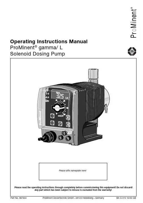
P r o M i n e n t®Operating Instructions Manual ProMinent ® gamma/ L Solenoid Dosing PumpPrintingPrinting:Operating Instructions ProMinent® gamma/ L© ProMinent Dosiertechnik GmbH, 1999Address:ProMinent Dosiertechnik GmbHIm Schuhmachergewann 5-11D-69123 HeidelbergPostfach 101760D-69007 Heidelberg*****************www.prominent.deSubject to technical alteration.Please fold out this page! ÈOperating-/Settings DiagramContinuous displayFunction DescriptionOperating modes Operating modes are selected using the MODE menu (depending upon identity code, someoperating modes may be absent)..“Analogue” operating mode: (Identity code, control variant: analogue current)The stroke rate is controlled via an analogue electrical signal via the “external control” terminal.Signal processing is pre-selected at the controller.“Manual” operating mode: (Identity code, control variant: manual, standard function)The stroke rate is controlled manually via the controller.“Contact” operating mode: (Identity code, control variant: external 1:1 / external with pulsecontrol)This operating mode offers the opportunity to make fine adjustments with small increase/decrease factors. Dosing can be activated by a pulse via the “external control” terminal or by asemiconductor element. With the “pulse control” option it is possible to pre-set a feed quantity(batch) or number of strokes (factor 0.01 to 99.99) via the control unit.“Batch” operating function: (identity code, control variant, external 1:1 / external with pulsecontrol)This operating mode offers the option of working with larger transfer factors (up to 65535).Metering can be triggered by pressing the P key or a pulse from the “external control” terminalvia a contact or semiconductor element. A batching quantity or number of strokes can be pre-selected via the control unit.Functions The following functions can be selected using the SET menu:“Calibrate” function:The gamma/ L can be operated in all operating modes including in calibrating mode. Thecorresponding continuous displays can show the actual feed quantity or the feed rate.Calibration is maintained within the stroke frequency range 0 - 180 strokes/ min. Calibration isalso maintained when a stroke frequency is altered up to ± 10 %.“Pressure level” function:It is possible to set different pressure levels.“Auxiliary frequency” function:It is possible to set a stroke rate in the SET menu, which may be activated via the “externalcontrol” terminal. This auxiliary frequency overrides all other pre-set stroke rate frequencies.“Flow” function:Stops the gamma/ L when the flow is insufficient. In the SET menu, the number of failed strokesis entered after which the pump will be turned off.The following functions are available as standard:“Float switch” function:Information on the liquid level in the feed chemical container is transmitted to the gamma/ L.This option requires the installation of a 2-stage float switch. This is connected to the “floatswitch” terminal.“Pause” function:The gamma/ L can be stopped by remote control via the “external control” terminal. The “pau-se” function operates only via the “external control” terminal.The following functions are activated by keystrokes:“Stop” function:The gamma/ L can be stopped by pressing the STOP/START key without disconnecting fromthe mains power supply.Function Description“Prime” function:Priming (short term feed at maximum frequency) is activated by pressing both arrow keys at thesame time.Optional relay The gamma/ L has two connection options.“Fault indicating relay” option:In the event of fault signals, warning signals or float switch activation signals, connects anelectrical circuit to trigger alarm sirens etc. The relay is retrofitted via an aperture in the powerend.“Fault indicating and pacing relay” option:Along with the fault indicating relay, the pacing relay produces an electrical impulse for everystroke. The relay is retrofitted via an aperture in the power end.Function and errorindicators The operating and error status is shown via the three LEDs and the “error” indicator on the LCD (see also section 12):LCD indicator If a fault occurs “error” will appear along with an additional fault warning.LED indicator Operating indicator (green)This indicator is lit as long as the gamma/ L is operating correctly.Warning indicator (yellow)This warning light appears if the gamma/ L electronics detect a situation that could lead to afault, e.g. “liquid levels low 1st stage”.Warning indicator (red)This warning light appears if a fault occurs, e.g. “liquid levels low 2nd stage”.Hierarchy of operating modes, functions and fault statusesThe different operating modes, functions and fault statuses each have a differing effect onwhether and how the gamma/ L functions. These effects are given below:1.Prime2.Fault, stop, pause3.Auxiliary frequency4.Manual, analogue, contact, batchto:1.“Prime” can be activated in any pump status (as long as it is operable)2.“Fault”, “stop” and “pause” stop all system parts up to “prime”.3.The stroke rate of the “auxiliary frequency” always overrides the existing operating strokerate.Commissioning / Operating8.2Diagrams for setting feed capacityGeneralS Open out the page showing the diagram of your pump type (see appendix).S Calculate the correction factor. Mark the operating pressure for your application in the dia-gram “correction factor depending upon operating pressure”.S Trace a line from this value vertically up to the curve and then horizontally left. Read off thecorrection factor.S Divide the required feed rate by the correction factor determined as above. Mark this value(l/h) on the “l/h” axis in the diagram “feed rate depending upon stroke length and strokerate”.S Trace a line horizontally from this value to the left. Trace a line from the intersection with thestraight line for the adjustable stroke frequencies vertically downwards to the “strokelength” axis.S Set the gamma/ L to one of the stroke frequencies determined in this way, and thecorresponding stroke length.The measurements for determining the feed rate for the following diagrams were carried outusing water and the correction factor was determined at a 70 % stroke length. Distribution ofthe feed rate across all material versions: -5 to +15 %.9OperatingThis section describes all operating options available to you when the gamma/ L is incontinuous display mode (no P key symbol in the LCD display).GUIDELINE•Open out the fold-out page following the title page fully! There you will find theoverviews “control elements and key functions” and “operating settings dia-gram”.•Look at the overview “continuous displays”. This page shows you which displaysare available in which operating mode, and which values are directly alterable inthe corresponding continuous displays.9.1Manual operationSet stroke length Stroke length is continually adjustable within a range of 0 - 100 %. The recommended strokelength range, which will practically guarantee technical reproducibility, is 30 - 100 % (SEK type:50 - 100 %).The following operating options are available via the different keys (see also figure on the nextpage):Stop/Start gamma/ L To stop gamma/ L: press STOP/START key.To start gamma/ L: press STOP/START key.Start batch Press the P key briefly in “batch” operating mode.Load factory settings Press the P key for 15 s to load factory calibration settings!Current settings will be deleted.Change to settings mode WeIf you press the P key for 2 s in any continuous display the gamma/ L will change to settingsmode (see section 7).If CODE 1 is set, the code must be entered after pressing the P key.Check adjustable values Each time you press the i key you will see a different continuous display. The number ofcontinuous displays depends upon the identity code, the selected operating mode and theconnected accessories.Change directlyalterable values To change a value (see below) directly in the corresponding continuous display, press one of thearrow keys until “set” appears in the LCD display. The delay has been programmed in to preventinadvertent changing of values.If CODE 2 has been set, this code must be entered after pressing the arrow key.Directly alterable values are as follows:。

Parker Hannifin Manufacturing Germany GmbH &Co.KG Registered office:Bielefeld District Court:Bielefeld HRA 15699Branch office Kelsterbachpersonally liable partner:Parker Hannifin GmbHFasanenweg 5,65451Kelsterbach,Germany Registered office:Bielefeld District Court:Bielefeld HRB 35489Tel.:+4961079039-0,Fax:+496107-64162Managing directors of Parker Hannifin GmbH:Dr.-Ing.Hans-Jürgen Haas,E-Mail:**********************Ellen Raahede Secher,Kees VeraartInternet:Chairman of the Supervisory Board:HansgeorgGreunerInstallation InstructionsHydrant Pit BoxWL5917©2017-This documentation is copyrightprotected.History of document versionsRevision Date Author Reason for change/commentsR0010.08.2017Documentation First creationTable of contentsHistory of document versions (2)Table of contents (2)1Introduction (3)1.1General information (3)1.1.1Purpose and aim of this document (3)1.1.2Abbreviations (3)1.1.3Glossary (3)1.1.4Literature and bibliography (3)1.2Description of the hydrant pit box (4)2Assembly of the hydrant pit box (4)2.1Procedure (4)2.1.1General information (4)2.1.2Welding on the inner housing (5)2.1.3Installation of the outer hydrant housing (5)2.1.4Integration of external hydrant housing in concrete (5)2.1.5Installation of the cover (5)3Assembling the hydrant pit valve (6)3.1Procedure (6)3.1.1General information (6)3.1.2Finish of flange sealing surfaces (6)3.1.3Visual inspection prior to installation (6)3.1.4Lubrication and lubricants (7)3.1.5Mounting and centering the seal (7)3.1.6Applying the required tightening torques (8)3.1.7Use of DIN flanges (9)3.1.8System for the tightening of screws (9)3.1.9Quality assurance and documentation of installation (10)3.1.10Pressure and leak testing (11)4Drawing E-5917-00Rev.3 (12)5Parts list E-5917-00Rev.3 (13)1Introduction1.1General information1.1.1Purpose and aim of this documentThe manual describes the operation of the hydrant pit box and aims to provide an overview of the activities for installation,risks,and workflows with any appropriate release procedures for all partici-pants.Wearing PPE,local policies and in particular the safety regulations,laws,and specifications must continue to be observed.1.1.2Abbreviationsbar Pressure unitBetrSichV Operational safety ordinance(replacement for VbF)DN Nominal diameterEx-R Explosion protection directives(ATEX)HSSE Health,Safety,Security and EnvironmentHSEQ Health,Safety,Environment and QualityPSA,PPE Personal Protective EquipmentSiGe Safety and health protection1.1.3GlossaryDispenser Tanker vehicle with hose,filter water separators and counters for the refuelling of aircraft on the apronFlusher Cleaning vehicle for cleaning the underground hydrant systemHydrant Connection point for the removal of fluids from pressure pipe systems.With avi-ation fuel systems,the refuelling of aircraft is effected via an underground kero-sene pipeline network and hydrants.Kerosene Fuel for jet engines and propeller turbines;very similar to paraffin.Kerosene is obtained by distillation of petroleum,similar to diesel and gasoline,but differentto these,can function without halogenated additives.The technical term is TurboFuel Jet A-1.Pit pipeline Underground pipeline from the distributor shaft to the underground hydrant pit valveTransfer station Structural equipment at the end of the transmission lineUndergroundhydrant pitvalveConnection point for the refuelling of aircraft by means of a dispenser1.1.4Literature and bibliography∙Relevant DIN,DIN EN and ISO standards∙DIN EN1591-1Tightening torques∙MIL-PRF-4556F1.2Description of the hydrant pit boxThe hydrant pit box is intended for the installation of API/IP-hydrant pit valves.It consists of an inner housing made of a steel welded construction and an outer housing made of spheroidal cast iron.To maintain cleanliness of the product and to protect against corrosion both housings are coated as follows:the inner sides are coated with Interline850according to MIL-PRF-4556F,and the outer sides with Poxitar F(epoxy black).To transfer vertical loads to the surroundings-concrete-the outer housing can slide vertically relative to the inner housing.To prevent the leakage of the product and of any contaminated surface water into the ground,a seal in the form of a bellows is fitted between the outer and inner housing.In the inner housing there is a welded-on6”riser flange,on which the hydrant pit valve and if required an isolating ball valve are mounted.A pipe is welded onto the outer side of the hydrant inner housing, which is welded to the pipes of the hydrant system by a certified specialist company.The hydrant pit box has a cover made of an aluminium alloy.It has a non-slip surface,a Buna"N"cover seal,and a nylon tether and is delivered depending on the required certification of the airport in the respective load class.The design of the underside of the cover allows rotation of the cover without twisting and buckling of the nylon tether.The nylon tether is attached to the hydrant pit box using the provided screw lugs at the inside of the hydrant pit box.Screw lugs for secure transport are located inside the hydrant pit box.2Assembly of the hydrant pit box2.1Procedure2.1.1General information2.1.1.1Regulations and work instructionsBetrSichV,HSSE,HSSQ,SiGe and internal work instructions and requirements are to be observed and adhered to,if applicable.2.1.1.2Transport-loading and unloadingThe hydrant pit box is delivered by a logistics company.The hydrant cabinet comes lashed,packed in shrink wrap on a wooden pallet.The offloading must be done professionally and properly with suitable loading and unloading equipment.The outer housing is placed onto the inner housing for transport purposes and secured with three(3) transport locks.2.1.2Welding on the inner housingTo weld on the inner housing to the piping system the three transport locks must be demounted,and then the outer housing can be removed.The welding on is done in accordance with the specifications and requirements for the pipework sys-tem to be connected.After welding,the coating of the pipe must be applied in accordance with the applicable requirements for the pipework system.Note:A blind flange must be installed on the riser flange for the pressure test of the complete system.2.1.3Installation of the outer hydrant housingBefore installing the outer hydrant housing the cover must be removed,and the outer housing is lifted up using suitable loading and unloading equipment on slings and hooks,so that it hangs freely and can be moved.Note:The outer casing must be aligned so that the distance between the sealing surface of the6"ANSI300 lbs riser flange and the top of the hydrant pit box respectively the surrounding concrete surface of the airfield is545mm.The three(3)transport locks are screwed to the screw lugs inside at the top of the pit box to fix the housing.Fine alignment of the housing to the surrounding concrete surface of the airfield is done by turning the nuts under the mounting flanges.2.1.4Integration of outer hydrant housing in concreteDuring the concrete work the following points must be observed:∙The concrete thickness around the hydrant cabinet must not be more than350mm,so that a vertical movement relative to the inner housing is ensured.∙The inner housing must be not set in concrete to avoid stress in the piping system.∙The transition between the outer and inner housing must remain free to ensure the vertical mobility.∙The top of the outer housing of the hydrant pit box should be aligned to the surrounding con-crete floor in a way that it stands slightly proud with a slight slope in the concrete around the pit box.This will prevent that surface water runs into the hydrant pit box as soon as the cover is removed.∙If the cover is mounted during the concrete works the cover seal must be protected so that it is not damaged.2.1.5Installation of the coverAfter the installation of the hydrant pit box the transport locking devices are removed first.∙The nylon tether of the cover is attached to one of the3lugs in the housing and secured witha cable clamp.∙Before inserting the cover the Buna"N"(O-ring)seal has to be checked,then the cover can be used.The cover must stand not more than1mm proud of the hydrant cabinet.To set the cover height,seals are available in different thicknesses.3Assembling the hydrant pit valve3.1Procedure3.1.1General informationBefore installation of the hydrant pit valve the distance between the surface of the riser flange and the top of the housing(equal to top of the housing cover)must be checked.Note:The distance must be545±5mm.If it is larger,it may be necessary to install an intermediate ring between riser flange and hydrant valve,to bridge the distance.The supplied seal must be fitted between riser flange and hydrant valve.The nuts are tightened with the specified torque.3.1.2Finish of flange sealing surfacesIf the flange sealing surfaces are supplied with a temporary coating,e.g.as corrosion protection,then this must be removed without residues prior to installation(e.g.with detergent and a suitable wire brush).Note:When exchanging seals,it must be ensured that the old seal is removed completely from the flange sealing surface,without the sealing surface being damaged.Note:Remnants of corrosion inhibitors on the flange sealing surfaces(with new flanges)adversely affect the leak tightness of flange connections as well as the removal of the seal remains in a subsequent ex-change of seals.3.1.3Visual inspection prior to installationMake sure that the flange sealing surfaces are clean,undamaged and flat.In particular,no radially running surface damages such as scratches or points of impact must be present.In case of doubt the damage must be examined by an expert on-site and the flange if necessary re-placed or refinished.Screws,nuts,and washers must be clean and undamaged.Pay particular attention to the threads and contact surfaces.Screws,nuts,and if necessary washers removed during assembly work are to be replaced with new according to the risk assessment or after testing in the event of ed screws,nuts,and wash-ers are allowed only to be reinstalled in the"as new"condition.The seal must be clean,undamaged and dry.The use of adhesives and assembly pastes is not allowed for ed seals must not be used again.In particular,seals with kinks should never be used,be-cause they pose a safety risk.Ensure that only seals which are free of defects and faults are provided to the assembly personnel.The manufacturer's instructions must be observed.3.1.4Lubrication and lubricantsTo minimise friction forces the sliding surfaces of the screws,nuts,and washers are to be treated with suitable lubricants before tightening.Optimal lubrication is given when all sliding surfaces such as the thread,the nut contact surface,and if necessary with moving screw head also the head contact surface is lubricated(see Figure1).Only in this way the required screw preload can be reached at the specified torque,and after exposure to temperature easy loosening of the screw connections is possible.All lubricants should be applied only as a thin film,but across complete surfaces.Excess lubrication has no advantages,neither with respect to friction reduction.The application can be done with a medium hard,non-shedding brush or a sponge.3.1.5Mounting and centering the sealThe correct mounting of the flange connections relies on matching flange plates without centre offset, which allow correct positioning of the seal without damage.Centering bolts should be used especially for stretch bolts as a mounting aid.Recommendation:Use centering bolts made of plastic,so that gap or misalignment cannot be levered with the bolt. The gap(non-parallelism of the sealing surfaces)before tightening of the screws can be regarded as of no consequence,as long as the permitted gap according to figure2is not exceeded.The gap has to be eliminated from the gaping side (a).NutNutWasherThreadThreadWasherWasherNutFigure1–Flange connection elements to be lubricated(left version with screw,right version with threaded bar)3.1.6Applying the required tightening torquesTo achieve the tightness class of L0,01,tightening torques were determined according to DIN EN1591-1(table1).For simplification,for a group of seals,nominal sizes,and PN-classes the calculation of the tightening torques has been optimised,so that for one screw size in conjunction with the seal group only one tightening torque can be set.In most cases,the permissible stresses for at least one part of the flange connection have been exhausted.The simplification achieved with this approach for practical applica-tion compensates the few cases of non-maximum load stresses.Note:Flanges made of austenitic steel and ferrite according to DIN EN1092-1are dimensionally the same. Table1-required tightening torques for mounting of flanges according to DIN EN1092-1type11and fasteners(such as screws,threaded rods)of25CrMo4/A2-70or comparable strength Figure2–Flange opening gaps and guideline values for permissible gap=a-bThreadTorqueTightening processSeal groupWith manual wrenchor if req.with exten-sionSeal groupWith torque wrenchor other torque-con-trolled processThese tightening torques were calculated by BASF SE and confirmed on occasion by cooperating companies.Recommended lever length300mmRecommended lever length550mm3.1.7Use of DIN flangesAlso for DIN flanges,whose sizes are identical to DIN EN1092-1,the tightening torques in table1apply for the nominal sizes and PN-classes shown in table2.Table2–nominal sizes and PN-classes of the previous DIN flangesThe smaller flange thickness of DIN flanges<DN50compared with EN flanges has no influence on the tightening torques.Austenitic weld neck flanges for machine welding according to PAS1057-6with reduced s-dimension (base wall thickness)are covered by the DIN flanges.3.1.8System for the tightening of screws3.1.8.1General informationThe order in which the nuts and bolts are tightened has a significant impact on the distribution of forces acting on the seal(surface pressure).Improper tightening leads to a high variation of bolt loads and can lead to falling below the required minimum surface pressure and to leaks.After tightening the nut at least two,but no more than five threads should protrude at the end of the screw(see also DIN78).Threaded rods are to be mounted so that the overhangs on both sides are about equal.Screw heads,nuts,and washers must have smooth contact.The screws are to be pre-assembled by hand,when doing so∙hardened washers according to DIN EN ISO7089with minimum hardness class200HV are to be placed under the nuts∙the screws are to be installed so that all screw heads are arranged on one side of the flange ∙with bolt connections where the screw head is turned(blind hole),put the washers under the bolt heads∙for horizontally arranged flanges place the screws from above∙stiff bolts should be replaced by smooth running ones∙it is possible to simultaneously use multiple tightening toolsPressure class Standard Nominal size3.1.8.2Tightening procedureThe screws are1.to be tightened cross-wise,as shown in figure3,with30%of the nominal torque2.to be tightened same as1.,with60%of the nominal torque3.to be tightened same as1.,with100%of the nominal torque4.tightend once more with full nominal torque around the circumference This process is to berepeated so often until the nuts no longer turn on applying the full torque.3.1.9Quality assurance and documentation of installation3.1.9.1Quality assuranceThe assembly class determines what measures are required for quality assurance,including the related documentation,see table3.Table3-measures for quality assurance by assembly class8screws12screws16screws20screws24screwsFigure3–Tightening process1:cross-wise tightening of the screwsAssembly class Quality assurance measuresNo continuous inspectionsSampling inspection-By assembly personnel(by a second technician)-Scope:2%of the flange connections-If deviations from the torque range are found the inspection scope is to be extended-DocumentationSampling inspection-By assembly personnel(by a second technician)-Scope:10%of the flange connections-If deviations from the torque range are found the inspection scope is to be extended-DocumentationCross-check-By an independent person-Scope:2%of the flange connections-Documentation-If deviations from the torque range are found the inspection scope is to be extended-11 Due to the settling behaviour of the seal,the check of the torque should be done4hours after instal-lation at the earliest.To determine the test torque,the torque is multiplied with the PQR value of the seal at the QA value of30MPa at room temperature taking into consideration the variation when tightening the screws.If the flange connection is checked immediately after installation,the tightening torques are to be used as test torques.The check of the tightening torque is done at the location where the screw connection was tightened. Usually,the nut is tightened.For this reason,here also the washer is installed.For the test,the torque wrench is set to the test torque.If the nut cannot be turned further,the required tightening torque has been applied.3.1.9.2DocumentationThe nature and extent of the documentation must be consistent with the respective operational man-agement system.The following list is an example.∙New creation:o Planning documentationo Isometricso Workshop drawingso Specificationso Schematic sketches∙Inspection or minor repairs:o Work cardso Repair specificationso Plant-specific opening and closing of flange connectionso Shift logo Repair bookFor the documentation of the assembly,for example the manufacturer certification including naming the participating installation technicians is sufficient.It is not necessary that the flange connection is associated with a specific technician.Thus,it would be sufficient for the documentation of the assem-bly for example that the staff involved in the assembly are named on the manufacturing and inspection certificates for pipes.An individual marking of flange connections can be useful.3.1.10Pressure and tightness testingPressure test(according to BetrSichV:Strength testing)and leakage tests(according to BetrSichV:ex-ternal examination)are to be carried out according to the assembly quality assurance.Montageanl_Hydrgeh_WL6576_E_201708R00.docx11of。
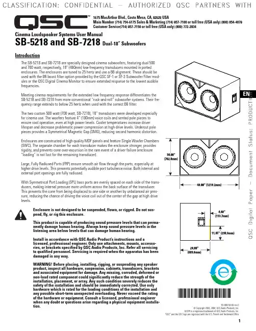
1*TD-000150-Cinema Loudspeaker Systems User ManualSB-5218 and SB-7218 Dual-18” SubwoofersIntroductionThe SB-5218 and SB-7218 are specially designed cinema subwoofers, featuring dual 500 and 700 watt, respectively, 18” (460mm) low-frequency transducers mounted in ported enclosures. The enclosures are tuned to 25 hertz and use a B6 alignment. These should be used with the B6 boost filter option provided by the QSC SF-1 or SF-3 Subwoofer Filter mod-ules or the QSC Digital Cinema Monitor to ensure extended response to the lowest audible frequencies.Meeting cinema requirements for the extended low frequency response differentiates the SB-5218 and SB-7218 from more conventional “rock-and-roll” subwoofer systems. Their fre-quency range extends to below 25 hertz when used with the correct B6 filter.The two custom 500 watt (700 watt, SB-7218), 18” transducers were developed especially for cinema use. The woofers feature 4” (100mm) voice coils and vented pole pieces to ensure cool operation, even at high power levels. Cooler temperatures increase driver lifespan and decrease problematic power compression at high drive levels. Undercut pole pieces provides a Symmetrical Magnetic Gap (SMG), reducing second harmonic distortion.Enclosures are constructed of high quality MDF panels and feature Single Woofer Chambers (SWC). The separate chamber for each transducer makes the enclosure stronger, provides rigidity, and prevents cone over-excursion in the rare event of a driver failure (enclosure “loading” is not lost for the remaining transducer).Large, Fully Radiused Ports (FRP) ensure smooth air flow through the ports, especially at higher drive levels. This prevents potentially audible port turbulence noise. Both internal and external port openings are fully radiused.With Symmetrical Port Loading (SPL) bass ports are evenly spaced on each side of the trans-ducers, making internal pressure more uniform across the back surface of the transducer. This prevents the cone from being displaced to one side or another by unbalanced air pres-sure, reducing the chance of driving the voice coil out of the center of the gap at high drive levels.Enclosure is not designed to be suspended, flown, or rigged. Do not sus-pend, fly, or rig this enclosure.This product is capable of producing sound pressure levels that can perma-nently damage human hearing. Always keep sound pressure levels in the listening area below levels that can damage human hearing.Install in accordance with QSC Audio Product’s instructions and alicensed, professional engineer. Only use attachments, mounts, accesso-ries, or brackets specified by QSC Audio Products, Inc. Refer all servicing to qualified personnel. Servicing is required when the apparatus has been damaged in any way.WARNING! Before placing, installing, rigging, or suspending any speaker product, inspect all hardware, suspension, cabinets, transducers, brackets and associated equipment for damage. Any missing, corroded, deformed or non-load rated component could significantly reduce the strength of the installation, placement, or array. Any such condition severely reduces the safety of the installation and should be immediately corrected. Use only hardware which is rated for the loading conditions of the installation and any possible short-term unexpected overloading. Never exceed the rating of the hardware or equipment. Consult a licensed, professional engineer when any doubt or questions arise regarding a physical equipment installa-tion.TD-000150-00 rev.C© Copyright 2003, 2004, QSC Audio Products, Inc.QSC® is a registered trademark of QSC Audio Products, Inc.“QSC” and the QSC logo are registered with the U.S. Patent and Trademark Office1675 MacArthur Blvd., Costa Mesa, CA, 92626 USAMain Number (714) 754-6175 Sales & Marketing (714) 957-7100 or toll free (USA only) (800) 854-4079Customer Service(714) 957-7150 or toll free (USA only) (800) 772-28342ConnectionsNormal Connection The SB-5218/7218 has barrier strip screw ter-minals for connection. The terminals accept up to #10 AWG stranded loudspeaker wiring. Use the largest wire size and shortest wire length possible for a given installation. Observe the polarity markings and keep polarity consistent throughout the system for best performance.Parallel Connection of Second SB-5218/7218The terminals marker SPK2 may be used to con-nect another SB-5218/7218 in parallel. Connect the wires as shown in the illustration, at right. Note: If the SB-5218/7218’s internal wiring has been modified in any way, this may not func-tion. If this is the case, remove the terminal cup and verify the presence of the factory yellow jumper and blue jumper wires; remedy as required or have the loudspeaker serviced.Individual Transducer Connection (requires modification)The transducers are wired in parallel inside the enclosure. If individual transducer connection is required, remove the terminal cup and remove the yellow and the blue jumper wires that are connected between the SPK1 and SPK2 termi-nals. Replace the terminal cup and mark the enclosure with a note of the modification.Normal Connection Example:Parallel Connection Example:Individual TransducerConnection Example:3Specifications (subject to change without notice)SB-5218SB-7218Frequency Range:24 - 100 Hz (±3 dB)22 - 100 Hertz (±3 dB)19 - 250 Hz useable range (-10 dB)19 - 250 Hertz useable range (-10 dB)Maximum Output:135 dB SPL calculated peak137 dB SPL calculated peak1 meter, half space, at rated rms power with 6 dB crest factor pink noise input, 25 - 250 Hertz.129 dBA SPL calculated maximum continuous 130.5 dBA SPL calculated maximum continuous1 meter. The dBA scale is typically used to identify sound sources which can cause permanent hearing loss.Impedance:4 ohms, nom. (3.2 @ 25 Hz., 62 @ 50 Hz.) 4 ohms, nom. (3.2 @ 27 Hz., 28 @ 48 Hz.)Maximum Input Power:100 hours of 6 dB crest factor 800 watts rms1200 watts rmspink noise, 25 - 250 Hertz2 hours of 6 dB crest factor1000 watts rms1500 watts rmspink noise, 25 - 250 Hertz, AES methodRecommended Amp Power:1600 watts rms maximum 2600 watts rms maximum Sensitivity:99.5 dB half space 101.0 dB half space (25 - 100 Hz, 1 watt, 1 m.)93.5 dB full space95.0 dB full spaceWeight:225 lbs. shipping, 205 lbs. net (102/93 kg.)230 lbs. shipping, 210 lbs. net (104/95 kg.)Both Models-Nominal Coverage:Omnidirectional (80 Hz)Recommended Processing:LF boost- freq.= 25 Hz, Q=2.0, gain= +6 dB. QSC DSP configurations are available at . Parameters for alternative processing hardware are available upon request.Connectors:Barrier strip screw terminals accept up to #10 AWG stranded wire. Four terminals: (two INPUT and two PARALLEL OUT). Drivers are internally wired in parallel. For independent transducer connection, remove blue jumper wire and yellow jumper wire on internal-side of terminal cup and mark enclosure accordingly.Transducers:Two 18” (457mm) high efficiency subwoofer transducers featuring vented 4” (100mm) copper voice coils on Kapton® formers. High excursion/low distortion design, with extremely high power handling, and low thermal and port com-pression.Enclosure:B6 alignment, vented enclosure with symmetrical port design, tuned to 25 Hz, constructed of medium density fibre-board and heavily braced. Features vandal resistant woofer mounting bolts.Size:30” wide X 48” high X 24” deep (762 mm X 1220 mm X 610 mm)4Warranty (USA only; other countries, see your dealer or distributor)DisclaimerQSC Audio Products, Inc. is not liable for any damage to amplifiers, or any other equipment that is caused by negligence or improper installation and/or use of this loudspeaker product. QSC Audio Products 3 Year Limited WarrantyQSC Audio Products, Inc. (“QSC”) guarantees its products to be free from defective material and / or workmanship for a period of three (3) years from date of sale, and will replace defective parts and repair malfunctioning products under this warranty when the defect occurs under normal installation and use - provided the unit is returned to our factory or one of our authorized service stations via pre-paid transportation with a copy of proof of purchase (i.e., sales receipt).This warranty provides that the examination of the return product must indicate, in our judgment, a manufacturing defect.This warranty does not extend to any product which has been subjected to misuse, neglect, accident, improper installation, or where the date code has been removed or defaced. QSC shall not be liable for incidental and/or consequential damages.This warranty gives you specific legal rights. This limited warranty is freely transferable during the term of the warranty period.Customer may have additional rights, which vary from state to state.In the event that this product was manufactured for export and sale outside of the United States or its territories, then this lim-ited warranty shall not apply. Removal of the serial number on this product, or purchase of this product from an unauthorized dealer, will void this limited warranty. Periodically, this warranty is updated. To obtain the most recent version of QSC’s war-ranty statement, please visit . Contact us at 800-854-4079 or visit our website at .Contacting QSC Audio ProductsMailing address:QSC Audio Products, Inc.1675 MacArthur BoulevardCosta Mesa, CA 92626-1468 USATelephone Numbers:Main Number (714) 754-6175Sales & Marketing (714) 957-7100 or toll free (USA only) (800) 854-4079Customer Service(714) 957-7150 or toll free (USA only) (800) 772-2834Facsimile Numbers:Sales & Marketing Fax(714) 754-6174Customer Service Fax(714) 754-6173World Wide Web: E-mail:*************************************QSC Audio Products, Inc. 1675 MacArthur Boulevard Costa Mesa, California 92626 USA ©2003, 2004 “QSC” and the QSC logo are registered with the U.S. Patent and Trademark Office.Kapton® is a registered trademark of E.I. du Pont de Nemours and Company.5Manual del usuario de los sistemas de altavoces para salas de cineSubwoofers dobles de 18"SB-5218 y SB-7218IntroducciónLos subwoofers SB-5218 y SB-7218 están especialmente diseñados para salas de cine, cuentan con dos transductores de baja frecuencia de 18” (460mm), de 500 y de 700 vatios,respectivamente, montados en cajas con puertos. Las cajas están afinadas a 25 hertz y usan una alineación B6. Deben usarse con la opción de filtro intensificador B6 proporcionada por los módulos de filtro de subwoofer QSC SF-1 o SF-3 o por el monitor de cine digital QSC para asegurar la respuesta extendida a las frecuencias audibles más bajas.El cumplimiento de los requisitos de salas de cine respecto a la respuesta extendida de baja frecuencia distingue a los subwoofers SB-5218 y SB-7218 de los sistemas de subwoofers tipo “rock-and-roll” más convencionales. Su intervalo de frecuencia se extiende por debajo de los 25 hertz cuando se usan con el filtro B6 correcto.Los dos transductores de 18", de 500 vatios (700 vatios para el SB-7218) se desarrollaronespecíficamente para su uso en salas de cine. Los woofers tienen bobinas de voz de 4” (100 mm) y polos ventilados para asegurar una operación fría, incluso a niveles de alta potencia. Lastemperaturas más frías aumentan la vida útil del excitador y reducen la problemática compresión de la potencia a niveles altos de excitación. El polo proyectado proporciona un campo magnético simétrico (Symmetrical Magnetic Gap, SMG), reduciendo la segunda deformación armós cajas están construidas con paneles MDF (cartón duro de densidad media) y tienen cámaras de woofer sencillo (Woofer Chambers, SWC). La cámara separada para cada transductorproporciona a la caja resistencia, rigidez, y evita la excursión excesiva del cono en el raro evento de una falla del excitador (la "carga" de la caja no se pierde para el transductor restante).Los grandes puertos totalmente redondeados (Fully Radiused Ports, FRP) aseguran un flujo de aire uniforme a su través, especialmente a niveles mayores de excitación. Esto evita ruido de turbulencia en el puerto potencialmente audible. Ambas aberturas del puerto, la interna y la externa, están totalmente redondeadas.Con la carga simétrica de los puertos (Symmetrical Port Loading, SPL), los puertos de bajos están igualmente separados a cada lado de los transductores, haciendo que la presión interna sea más uniforme a través de la superficie posterior del transductor. Esto evita que el cono sea desplazado de un lado a otro por la presión no equilibrada del aire, reduciendo la probabilidad de impulsar la bobina de voz fuera del centro del espacio a altos niveles de excitación.La caja no está diseñada para montarse suspendida, en voladizo ni sobre arneses. No suspenda esta caja, no la monte en voladizo ni sobre arneses.Este producto es capaz de producir niveles de presión del sonido que pueden causar daños permanentes al oído humano. Siempre mantenga los niveles de presión del sonido en un área de audición con un nivel menor que el que provoca daños al oído humano.Instale de acuerdo con las instrucciones de QSC Audio Products y de un ingeniero profesional con la debida licencia. Sólo use piezas, montajes,accesorios y soportes especificados por QSC Audio Products, Inc. Refiera todo el servicio a personal calificado. Cuando el aparato haya sido dañado de alguna manera, es necesario proporcionarle servicio.¡ADVERTENCIA! Antes de colocar, instalar, montar o suspender cualquier producto de altavoz, inspeccione todo el herraje, la suspensión, los armarios, los transductores, los soportes y el equipo asociado para detectar laexistencia de daños. Cualquier componente faltante, corroído, deformado, o sin carga nominal podría reducir significativamente la resistencia de lainstalación, la colocación o la configuración. Cualquier condición de este tipo reduce gravemente la seguridad de la instalación y debe corregirse deinmediato. Use sólo herraje que esté clasificado para las condiciones de carga de la instalación y cualquier carga excesiva a corto plazo inesperada posible. Nunca exceda el valor nominal del herraje ni del dispositivo. Consulte a un ingeniero profesional con la debida licencia cuando surjan dudas o preguntas referentes a la instalación física del equipo.*TD-000150-TD-000150-00 rev.C© Derechos de autor 2003, 2004, QSC Audio Products, Inc.QSC® es una marca comercial registrada de QSC Audio Products, Inc.“QSC” y el logotipo de QSC están registrados con la Oficina de Patentes y MarcasComerciales de los Estados Unidos1675 MacArthur Blvd., Costa Mesa, CA, 92626 EE.UU.Número principal +1 (714) 754-6175 Ventas y Comercialización +1 (714) 957-7100 o línea sin costo (sólo para EE.UU.) +1 (800) 854-4079Servicio al cliente +1 (714) 957-7150 o línea sin costo (sólo en EE.UU.) +1 (800) 772-28346ConexionesConexión normalEl SB-5218/7218 tiene terminales de tornillo de barra protectora para su conexión. Losterminales aceptan cableado trenzado de hasta #10 AWG para altavoces. Use el alambre del calibre más grande y de la longitud más corta posible en cualquier instalación. Observe las marcas de polaridad y mantenga la polaridad uniforme en todo el sistema para permitir el mejor rendimiento.Conexión en paralelo de un segundo SB-5218/7218Los terminales marcadores SPK2 se pueden usar para conectar en paralelo otro SB-5218/7218. Conecte los cables como se como se muestra en la ilustración, a la derecha. Nota: si el cableado interno de SB-5218/7218 se ha modificado de alguna manera, es posible que no funcione. En este caso, quite la cúpula del terminal y verifique la presencia de alambres amarillos y azules de puentes instalados en fábrica; corrija el problema según se requiera, o solicite que den servicio al altavoz.Conexión del transductor individual(requiere modificación)Los transductores están conectados en paralelo dentro de la caja. Si se requiere la conexión del transductor individual, quite la cúpula del terminal y quite los alambres amarillo y azul del puente que están conectados entre los terminales SPK1 y SPK2. Vuelva a colocar la cúpula del terminal y marque la caja con una nota que indique la modificación.transductor individual:Ejemplo de una conexión normal:Ejemplo de conexiónen paralelo:7Especificaciones (sujetas a cambio sin previo aviso).SB-5218SB-7218Intervalo de frecuencia:24 - 100 Hz (±3 dB)22 - 100 Hertz (±3 dB)Intervalo útil de 19 - 250 Hz (-10 dB)Intervalo útil de 19 - 250 Hertz (-10 dB)Salida máxima:Pico calculado de SPL: 35 dBPico calculado de SPL: 137 dB1 metro, medio espacio, a una potencia rms nominal con entrada de ruido rosa con factor de cresta de 6 dB, 25 - 250 Hertz.Máximo calculado continuo de SPL: 129 dBA Máximo calculado continuo de SPL: 130.5 dBA1 metro. La escala de dBA típicamente se usa para identificar fuentes de sonido que pueden causar pérdida auditiva permanenteImpedancia:4 ohms, nom. (3.2 a 25 Hz., 62 a 50 Hz.) 4 ohmios, nom. (3.2 a 27 Hz., 28 a 48 Hz.)Potencia máxima de entrada:100 horas de factor de cresta de 6 dB 800 vatios rms 1200 vatios rmsruido rosa, 25 - 250 Hertz2 horas de factor de cresta de 6 dB 1000 vatios rms 1500 vatios rmsruido rosa, 25 - 250 Hertz, método AESPotencia de amperaje recomendada:1600 vatios rms como máximo 2600 vatios rms como máximo Sensibilidad:99.5 dB medio espacio 101.0 dB medio espacio (25 - 100 Hz, 1 vatio, 1 m.)93.5 dB espacio completo95.0 dB espacio completoPeso:225 libras envío, 205 libras neto (102/93 kg.)230 libras envío, 210 libras neto (104/95 kg.)Ambos modelos:Cobertura nominal:Omnidireccional (80 Hz)Procesamiento recomendado:Intensificador de baja frecuencia- frec.= 25 Hz, Q=2.0, ganancia +6 dB. Las configuraciones DSP de QSC estándisponibles en . Los parámetros para el herraje de procesamiento alternativo están disponibles si así se solicitan.Conectadores:Los terminales de tornillo de barra protectora aceptan alambre trenzado de hasta #10 AWG . Cuatro terminales: (dos de ENTRADA y dos de SALIDA PARALELA). Los excitadores están cableados internamente en paralelo. Para la conexión de un transductor independiente, quite los alambres azul y amarillo de los puentes que se encuentran en el lado interno de la cúpula del terminal y marque la caja de acuerdo con esto.Transductores:Dos transductores de subwoofer, de alta eficiencia, de 18” (457mm), con bobinas de voz de cobre de 4” (100mm) ventiladas, en soportes de Kapton®. Diseño de alta excursión/baja deformación, con un manejo de potencia extremadamente alta, y baja compresión térmica y de puerto.Caja:Alineación B6, caja ventilada con diseño de puertos simétricos, afinada a 25 Hz, construida con cartón duro de media densidad y fuertemente soportado. Tiene pernos de montaje del woofer resistentes al vandalismo.Tamaño:30” de ancho X 48” de alto X 24” de profundidad (762 mm X 1220 mm X 610 mm)8Garantía (sólo en EE.UU.; en otros países, consulte a su concesionario o distribuidor)RenunciaQSC Audio Products, Inc. no es responsable por ningún daño a los amplificadores, ni a ningún otro equipo que sea causado por negligencia o instalación y/o uso inadecuado de este altavoz. Garantía limitada de 3 años de QSC Audio ProductsQSC Audio Products, Inc. (“QSC”) garantiza que sus productos estarán libres de materiales y/o mano de obra defectuosos por un periodo de tres (3) años a partir de la fecha de la venta, y reemplazará las piezas defectuosas y reparará los productos que funcionen mal bajo esta garantía cuando el defecto ocurra bajo condiciones normales de instalación y uso, siempre y cuando la unidad se devuelva a nuestra fábrica o a una de nuestras estaciones autorizadas de servicio mediante transportación prepagada con una copia del comprobante de compra (por ejemplo, el recibo de la compra).Esta garantía requiere que el examen del producto devuelto indique, en nuestra opinión, un defecto de fabricación.Esta garantía no se extiende a ningún producto que hubiera estado sometido a uso indebido, negligencia, accidente, instalación incorrecta, o en el que se hubiera quitado o modificado el código de la fecha. QSC tampoco será responsable por daños incidentales y/o emergentes.Esta garantía le otorga derechos legales específicos. Esta garantía limitada es libremente transferible durante el período de la misma.El cliente podría gozar de derechos adicionales, que podrían variar de un estado a otro.En caso de que este producto fuera fabricado para exportación y venta fuera de los Estados Unidos o sus territorios, entonces no será aplicable esta garantía limitada. La eliminación del número de serie en este producto, o la compra de este producto de un distribuidor no autorizado, anularán esta garantía limitada. Esta garantía se actualiza periódicamente. Para obtener la versión más reciente de la declaración de garantía de QSC, visite . Comuníquese con nosotros llamando al 800-854-4079 o visite nuestro sitio en Internet en .Cómo comunicarse con QSC Audio ProductsDirección postal:QSC Audio Products, Inc.1675 MacArthur BoulevardCosta Mesa, CA 92626-1468 EE.UU.Números de teléfono:Número principal +1 (714) 754-6175Ventas y Comercialización +1 (714) 957-7100 o número sin costo (sólo EE.UU.) +1 (800) 854-4079Servicio al cliente +1 (714) 957-7150 o línea sin costo (sólo en EE.UU.) +1 (800) 772-2834Números de fax:Ventas y Comercialización Fax +1 (714) 754-6174Servicio al Cliente Fax +1 (714) 754-6173World Wide Web: Direcciónelectrónica:*************************************QSC Audio Products, Inc. 1675 MacArthur Boulevard Costa Mesa, California 92626 EE.UU.“QSC” y el logo QSC están registrados con la Oficina de Patentes y Marcas Comerciales de EE.UU.Kapton® es una marca comercial registrada de E.I. du Pont de Nemours and Company.9Manuel d'utilisation de systèmes de haut-parleurs de cinéma Doubles caisson d'extrêmes graves de 45,7cmSB-5218 etSB-7218IntroductionLes modèles SB-5218 et SB-7218 sont des caissons d'extrêmes graves spécialement conçus à partir de deux transducteurs basse fréquence de 460mm de 500 et 700W, respectivement enfermés dans des enceintes résonnantes. Les enceintes sont réglées à 25Hz et utilisent un alignement B6. Elles doivent être utilisées avec le filtre d'appoint B6 proposé avec les modules de filtres de caissons d'extrêmes graves QSC SF-1 ou SF-3 ou le moniteur de cinéma numérique QSC pour garantir une réponse étendue aux plus basses fréquences audibles.La satisfaction des exigences des salles de cinéma en matière de réponse basse fréquence étendue différencie les modèles SB-5218 et SB-7218 des systèmes de caissons d'extrêmes graves du type «rock-and-roll », plus conventionnels. Leur plage de fréquence atteint moins de 25 Hz lorsqu'ils sont utilisés avec le filtre B6 correct.Les deux transducteurs personnalisés de 45,7cm/500 W (700 W pour le modèle SB-7218) ont été spécialement développés pour les salles de cinéma. Les caissons d'extrêmes graves ont des bobines mobiles de 100mm et des sections de pôle à évents pour éviter la surchauffe, même à grande puissance. Les basses températures augmentent la durée de vie de l'étage d'attaque et diminuent la compression de puissance problématique à grande puissance. Les sections de pôle évidées assurent un espace magnétique symétrique (SMG), ce qui réduit la distorsion harmonique secondaire.Les enceintes sont faites de panneaux de MDF de haute qualité et ont des compartiments indépendants pour caissons d'extrêmes graves (SWC). Le compartiment séparé pour chaque transducteur rend l'enceinte plus solide, procure une certaine rigidité et empêche ledépassement de course du cône dans l'éventualité rarissime d'une panne d'étage d'attaque (le «chargement » de l'enceinte n'est pas interrompu pour l'autre transducteur).Les grands ports entièrement arrondis (FRP) garantissent la circulation d'air uniforme à travers les ports, surtout à haute puissance. Ceci empêche les interférences sonores. Les ouvertures internes et externes des ports sont entièrement arrondies.Grâce au chargement symétrique des ports (SPL), les ports à graves sont équidistants de part et d'autre des transducteurs, ce qui répartit uniformément la pression interne à travers la surface arrière du transducteur. Ceci empêche le déplacement du cône d'un côté ou de l'autre par un déséquilibre de la pression d'air, ce qui réduit le risque d'excentrage de la bobine mobile à haute puissance.L'enceinte n'a pas été conçue pour être suspendue, balancée ou montée. La suspension , le balancement ou le montage de l'enceinte sont interdits.Ce produit est capable de produire des niveaux de pression sonoresusceptibles d'endommager l'ouïe de manière irréversible. Toujours maintenir les niveaux de pression sonore dans la zone d'écoute en deçà de niveaux susceptibles de compromettre l'ouïe.Installer conformément aux instructions de QSC Audio Products et d’untechnicien professionnel diplômé. Utiliser uniquement des fixations, supports, accessoires ou équerres spécifiés par QSC Audio Products. Confier toutes les réparations à un personnel qualifié. Une réparation ou maintenance est requise lorsque l’appareil a été endommagé d’une manière quelconque.AVERTISSEMENT ! Avant de placer, installer, monter ou suspendre un haut-parleur, inspecter l’état de toute la visserie, du matériel de suspension, des armoires, des transducteurs, des supports et du matériel associé. Toutcomposant manquant, corrodé, déformé ou non adapté à la charge risque de réduire sensiblement la solidité de l’installation, sa mise en place ou sa portée. Une telle condition réduit sensiblement la sécurité de l’installation et doit être immédiatement corrigée. Utiliser uniquement du matériel de montage prévu pour les conditions de charge de l’installation et toute surcharge éventuelle à court terme imprévue. Ne jamais dépasser les spécifications nominales du matériel de montage ou de l’équipement. Consulter un technicienprofessionnel diplômé en cas de doute ou de question concernant l’installation physique de l’équipement.*TD-000150-TD-000150-00 rév. C© Copyright 2003, 2004, QSC Audio Products, Inc.QSC® est une marque déposée de QSC Audio Products, Inc.QSC et le logo QSC sont des marques déposées auprès de l'U.S. Patent andTrademark Office.1675 MacArthur Blvd., Costa Mesa, CA 92626Téléphone (standard)+1 (714) 754-6175 Ventes et Marketing +1 (714) 957-7100 ou +1 (800) 854-4079 (numéro vert valable aux États-Unis seulement)Service clientèle +1 (714) 957-7150 ou numéro vert (États-Unis seulement) +1 (800) 772-2834。

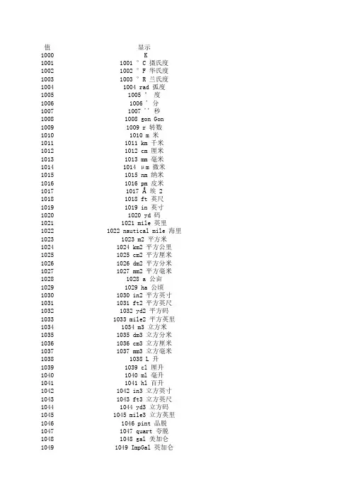
值显示1000 K10011001 °C 摄氏度10021002 °F 华氏度10031003 °R 兰氏度10041004 rad 弧度10051005 ° 度10061006 ' 分10071007 '' 秒10081008 gon Gon 10091009 r 转数10101010 m 米10111011 km 千米10121012 cm 厘米10131013 mm 毫米10141014 μm 微米10151015 nm 纳米10161016 pm 皮米10171017 Å 埃 2 10181018 ft 英尺10191019 in 英寸10201020 yd 码10211021 mile 英里10221022 nautical mile 海里10231023 m2 平方米10241024 km2 平方公里10251025 cm2 平方厘米10261026 dm2 平方分米10271027 mm2 平方毫米10281028 a 公亩10291029 ha 公顷10301030 in2 平方英寸10311031 ft2 平方英尺10321032 yd2 平方码10331033 mile2 平方英里10341034 m3 立方米10351035 dm3 立方分米10361036 cm3 立方厘米10371037 mm3 立方毫米10381038 L 升10391039 cl 厘升10401040 ml 毫升10411041 hl 百升10421042 in3 立方英寸10431043 ft3 立方英尺10441044 yd3 立方码10451045 mile3 立方英里10461046 pint 品脱10471047 quart 夸脱10481048 gal 美加仑10491049 ImpGal 英加仑10501050 bushel 蒲式耳10511051 bbl 桶 = 42 加仑10521052 bbl(liq) 液体桶 = 31.5 加仑10531053 ft3 std. 标准立方英尺10541054 s 秒10551055 ks 千秒10561056 ms 毫秒10571057 μs 微秒10581058 min 分10591059 h 小时10601060 d 天10611061 m/s 米/秒10621062 mm/s 毫米/秒10631063 m/h 米/小时10641064 km/h 千米/小时10651065 knot 节10661066 in/s 英寸/秒10671067 ft/s 英尺/秒10681068 yd/s 码/秒10691069 in/min 英寸/分10701070 ft/min 英尺/分10711071 yd/min 码/分10721072 in/h 英寸/小时10731073 ft/h 英尺/小时10741074 yd/h 码/小时10751075 mi/h 英里/小时10761076 m/s2 米/秒平方10771077 Hz 赫兹10781078 THz 太赫兹10791079 GHz 千兆赫10801080 MHz 兆赫10811081 kHz 千赫10821082 1/s /秒10831083 1/min /分10841084 rad/s 转/秒10851085 r/min 转/分10861086 rad/s 弧度/秒10871087 1/s2/秒平方10881088 kg 千克10891089 g 克10901090 mg 毫克10911091 Mg 兆克10921092 t 公吨10931093 oz 盎司10941094 lb 磅10951095 STon 美吨(短吨)10961096 LTon 英吨(长吨)10971097 kg/m3 千克/立方米10981098 Mg/dm3 兆克/立方米10991099 kg/dm3 千克/立方分米11001100 g/cm3 克/立方厘米11011101 g/m3 克/立方米11021102 t/m3 公吨/立方米11031103 kg/L 千克/升11041104 g/ml 克/毫升11051105 g/L 克/升11061106 lb/in3 磅/立方英寸11071107 lb/ft3 磅/立方英尺11081108 lb/gal 磅/美加仑11091109 STon/yd3 美吨/立方码11101110 °Twad 特瓦德耳度11111111 °Baum (hv) 波美度(重)11121112 °Baum (lt) 波美度(轻)11131113 °API API 度11141114 SGU Specific gravity units 11151115 kg/m 千克/米11161116 mg/m 毫克/米11171117 tex 特11181118 kg·m2 千克/平方米11191119 kg·m/s 千克·米/秒11201120 N 牛顿11211121 MN 兆牛11221122 kN 千牛11231123 mN 毫牛11241124 μN 微牛11251125 kg·m2/s 千克·平方米/秒11261126 N·m 牛·米11271127 MN·m 兆牛·米11281128 kN·m 千牛·米11291129 mN·m 毫牛·米11301130 Pa 帕斯卡11311131 GPa 吉帕11321132 MPa 兆帕11331133 kPa 千帕11341134 mPa 毫帕11351135 μPa 微帕11361136 hPa 百帕11371137 bar 巴11381138 mbar 毫巴11391139 torr 托11401140 atm 大气压11411141 psi 磅/平方英寸11421142 psia 磅/平方英寸(绝对压力)11431143 psig 磅/平方英寸 (gauge) 11441144 g/cm2 克/平方厘米11451145 kg/cm2 千克/平方厘米11461146 inH2O 英寸水柱11471147 inH2O (4°C) 4 摄氏度下英寸水柱11481148 inH2O (68°F) 68 华氏度下英寸水柱11491149 mmH2O 毫米水柱 1 11501150 mmH2O (4°C) 4 摄氏度下毫米水柱 1 11511151 mmH2O (68°F) 68 华氏度下毫米水柱 111521152 ftH2O 英尺水柱 1 11531153 ftH2O (4°C) 4 摄氏度下英尺水柱 1 11541154 ftH2O (68°F) 68 华氏度下英尺水柱 1 11551155 inHg 英寸汞柱11561156 inHg (0°C) 0 摄氏度下英寸汞柱11571157 mmHg 毫米汞柱11581158 mmHg (0°C) 0 摄氏度下毫米汞柱11591159 Pa·s 帕·秒11601160 m2/s 平方米/秒11611161 P 泊11621162 cP 厘泊11631163 St 斯托克斯11641164 cSt 厘司11651165 N/m 牛/米11661166 mN/m 毫牛/米11671167 J 焦耳11681168 EJ 10 的 18 次方焦耳11691169 PJ 拍焦耳11701170 TJ 太焦耳11711171 GJ 吉焦耳11721172 MJ 兆焦耳11731173 kJ 千焦耳11741174 mJ 毫焦耳11751175 W·h 瓦时11761176 TW·h 万亿瓦时11771177 GW·h 千兆瓦时11781178 MW·h 兆瓦时11791179 kW·h 千瓦时11801180 calth 卡路里(热化学)1 11811181 kcalth 千卡(热化学)1 11821182 Mcalth 兆卡(热化学)1 11831183 Btuth 英热单位 1 11841184 datherm 百万英热单位11851185 ft·lbf 英尺·磅11861186 W 瓦特11871187 TW 万亿瓦11881188 GW 千兆瓦11891189 MW 兆瓦11901190 kW 千瓦11911191 mW 毫瓦11921192 μW 微瓦11931193 nW 纳瓦11941194 pW 皮瓦11951195 Mcalth/h 兆卡/小时 1 11961196 MJ/h 兆焦/小时11971197 Btuth/h 英热单位/小时 1 11981198 hp 马力11991199 W/(m·K) 瓦/米·开12001200 W/(m2·K) 瓦/(平方米·开) 12011201 m2·K/W 平方米·开/瓦12021202 J/K 焦/开12031203 kJ/K 千焦/开12041204 J/(kg·K) 焦/(千克·开) 12051205 kJ/(kg·K) 千焦/(千克·开) 12061206 J/kg 焦/千克12071207 MJ/kg 兆焦/千克12081208 kJ/kg 千焦/千克12091209 A 安培12101210 kA 千安12111211 mA 毫安12121212 μA 微安12131213 nA 纳安12141214 pA 皮安12151215 C 库仑12161216 MC 兆库12171217 kC 千库12181218 μC 微库12191219 nC 纳库12201220 pC 皮库12211221 A·h 安时12221222 C/m3 库/立方米12231223 C/mm3 库/立方毫米12241224 C/cm3 库/立方厘米12251225 kC/m3 千库/立方米12261226 mC/m3 毫库/立方米12271227 μC/m3 微库/立方米12281228 C/m2 库/平方米12291229 C/mm2 库/平方毫米12301230 C/cm2 库/平方厘米12311231 kC/m2 千库/平方米12321232 mC/m2 毫库/平方米12331233 μC/m2 微库/平方米12341234 V/m 伏/米12351235 MV/m 兆伏/米12361236 kV/m 千伏/米12371237 V/cm 伏/厘米12381238 mV/m 毫伏/米12391239 μV/m 微伏/米12401240 V 伏特12411241 MV 兆伏12421242 kV 千伏12431243 mV 毫伏12441244 μV 微伏12451245 F 法拉12461246 mF 毫法12471247 μF 微法12481248 nF 纳法12491249 pF 皮法12501250 F/m 法/米12511251 μF/m 微法/米12521252 nF/m 纳法/米12531253 pF/m 皮法/米12541254 C·m 库·米12551255 A/m2 安/平方米12561256 MA/m2 兆安/平方米12571257 A/cm2 安/平方厘米12581258 kA/m2 千安/平方米12591259 A/m 安/米12601260 kA/m 千安/米12611261 A/cm 安/厘米12621262 T 特斯拉12631263 mT 毫特斯拉12641264 μT 微特斯拉12651265 nT 纳特斯拉12661266 Wb 韦伯12671267 mWb 毫韦伯12681268 Wb/m 韦伯/米12691269 kWb/m 千韦伯/米12701270 H 亨利12711271 mH 毫亨12721272 μH 微亨12731273 nH 纳亨12741274 pH 微微亨12751275 H/m 亨/米12761276 μH/m 微亨/米12771277 nH/m 纳亨/米12781278 A·m2 安·平方米12791279 N·m2/A 牛·平方米/安12801280 Wb·m 韦伯·米12811281 Ω 欧姆 1 12821282 GΩ 吉欧 1 12831283 MΩ 兆欧 1 12841284 kΩ 千欧 1 12851285 mΩ 毫欧 1 12861286 μΩ 微欧 1 12871287 S 西门子12881288 kS 千西12891289 mS 毫西12901290 μs 微西12911291 Ω·m 欧姆·米 1 12921292 GΩ·m 吉欧·米 1 12931293 MΩ·m 兆欧·米 1 12941294 kΩ·m 千欧·米 1 12951295 Ω·cm 欧姆·厘米 1 12961296 mΩ·m 毫欧·米 1 12971297 μΩ·m 微欧·米 1 12981298 nΩ·m 纳欧·米 1 12991299 S/m 西/米13001300 MS/m 兆西/米13011301 kS/m 千西/米13021302 mS/cm 毫西/厘米13031303 μS/mm 微西/毫米13041304 1/H /亨13051305 sr 球面度13061306 W/sr 瓦/球面度13071307 W/(sr·m2) 瓦/(球面度·平方米) 13081308 W/(m2) 瓦/平方米13091309 lm 流明13101310 lm·s 流·秒13111311 lm·h 流·小时13121312 lm/m2 流/平方米13131313 lm/W 流/瓦13141314 lx 勒克斯13151315 lx·s 勒克斯·秒13161316 cd 坎德拉13171317 cd/m2 坎德拉/平方米13181318 g/s 克/秒13191319 g/L 克/分13201320 g/h 克/小时13211321 g/d 克/天13221322 kg/s 千克/秒13231323 kg/min 千克/分13241324 kg/h 千克/小时13251325 kg/d 千克/天13261326 t/s 公吨/秒13271327 t/min 公吨/分13281328 t/h 公吨/小时13291329 t/d 公吨/天13301330 lb/s 磅/秒13311331 lb/min 磅/分13321332 lb/h 磅/小时13331333 lb/d 磅/天13341334 STon/s 美吨/秒13351335 STon/min 美吨/分13361336 STon/h 美吨/小时13371337 STon/d 美吨/天13381338 LTon/s 英吨/秒13391339 LTon/min 英吨/分13401340 LTon/h 英吨/小时13411341 LTon/d 英吨/天13421342 % 百分比13431343 % sol/wt 百分比固体/重量单位13441344 % sol/vol 百分比固体/体积单位13451345 % stm qual 百分比蒸汽质量13461346 °Plato plato 度13471347 m3/s 立方米/秒13481348 m3/min 立方米/分13491349 m3/h 立方米/小时13501350 m3/d 立方米/天13511351 L/s 升/秒13521352 L/min 升/分13531353 L/h 升/小时13541354 L/d 升/天13551355 ML/d 兆升/天13561356 ft3/s 立方英尺/秒13571357 ft3/m 立方英尺/分13581358 ft3/h 立方英尺/小时13591359 ft3/d 立方英尺/天13601360 ft3/min std 标准立方英尺/分13611361 ft3/h std 标准立方英尺/小时13621362 gal/s 美加仑/秒13631363 gal/min 美加仑/分13641364 gal/h 美加仑/小时13651365 gal/d 美加仑/天13661366 Mgal/d 兆美加仑/天13671367 ImpGal/s Imperial 加仑/秒13681368 ImpGal/min Imperial 加仑/分13691369 ImpGal/h Imperial 加仑/小时13701370 ImpGal/d Imperial 加仑/天13711371 bbl/s 桶/秒13721372 bbl/min 桶/分13731373 bbl/h 桶/小时13741374 bbl/d 桶/天13751375 W/m2 瓦/平方米13761376 mW/m2 毫瓦/平方米13771377 μW/m2 微瓦/平方米13781378 pW/m2 皮瓦/平方米13791379 Pa·s/m3 帕·秒/立方米13801380 N·s/m 牛·秒/米13811381 Pa·s/m 帕·秒/米13821382 B 贝尔13831383 dB 分贝13841384 mol Mol 13851385 kmol 千摩13861386 mmol 毫摩13871387 μmol 微摩13881388 kg/mol 千克/摩13891389 g/mol 克/摩13901390 m3/mol 立方米/摩13911391 dm3/mol 立方分米/摩13921392 cm3/mol 立方厘米/摩13931393 L/mol 升/摩13941394 J/mol 焦/摩13951395 kJ/mol 千焦/摩13961396 J/(mol·K) 焦/(摩·开) 13971397 mol/m3 摩/立方米13981398 mol/dm3 摩/立方分米13991399 mol/L 摩/升14001400 mol/kg 摩/千克14011401 mmol/kg 毫摩/千克14021402 Bq 贝克勒尔14031403 MBq 兆贝克勒尔14041404 kBq 千贝克勒尔14051405 Bq/kg 贝克勒尔/千克14061406 kBq/kg 千贝克勒尔/千克14071407 MBq/kg 兆贝克勒尔/千克14081408 Gy 戈瑞14091409 mGy 毫戈瑞14101410 rd 拉德14111411 Sv 西弗特14121412 mSv 毫西弗特14131413 rem 雷姆14141414 C/kg 库/千克14151415 mC/kg 毫焦/千克14161416 R 伦琴14171417 1/Jm3 磁能密度14181418 e/Vm314191419 m3/C 立方米/库14201420 V/K 伏/开14211421 mV/K 毫伏/开14221422 pH pH 值14231423 ppm 百万分率14241424 ppb 十亿分率14251425 ppth 万亿分率14261426 °Brix 白利糖度14271427 °Ball 巴林度14281428 proof/vol 标准酒精强度/体积14291429 proof/mass 标准酒精强度/质量14301430 lb/ImpGal 磅/Imperial 加仑14311431 kcalth/s 千卡/秒 1 14321432 kcalth/min 千卡/分 1 14331433 kcalth/h 千卡/小时 1 14341434 kcalth/d 千卡/天 1 14351435 Mcalth/s 兆卡/秒 1 14361436 Mcalth/min 兆卡/分 1 14371437 Mcalth/d 兆卡/天 1 14381438 kJ/s 千焦/秒14391439 kJ/min 千焦/分14401440 kJ/h 千焦/小时14411441 kJ/d 千焦/天14421442 MJ/s 兆焦/秒14431443 MJ/min 兆焦/分14441444 MJ/d 兆焦/天14451445 Btuth/s 英热单位/秒 1 14461446 Btuth/min 英热单位/分 1 14471447 Btuth/d 英热单位/天 1 14481448 μgal/s 微美加仑/秒14491449 mgal/s 毫美加仑/秒14501450 kgal/s 千美加仑/秒14511451 Mgal/s 兆美加仑/秒14521452 μgal/min 微美加仑/分14531453 mgal/min 毫美加仑/分14541454 kgal/min 千美加仑/分14551455 Mgal/min 兆美加仑/分14561456 μgal/h 微美加仑/小时14571457 mgal/h 毫美加仑/小时14581458 kgal/h 千美加仑/小时14591459 Mgal/h 兆美加仑/小时14601460 μgal/d 微美加仑/天14611461 mgal/d 毫美加仑/天14621462 kgal/d 千美加仑/天14631463 μImpGal/s 微 Imperial 加仑/秒14641464 mImpGal/s 毫 Imperial 加仑/秒14651465 kImpGal/s 千 Imperial 加仑/秒14661466 MImpGal/s 兆 Imperial 加仑/秒14671467 μImpGal/min 微 Imperial 加仑/分14681468 mImpGal/min 毫 Imperial 加仑/分14691469 kImpGal/min 千 Imperial 加仑/分14701470 MImpGal/min 兆 Imperial 加仑/分14711471 μImpGal/h 微 Imperial 加仑/小时14721472 mImpGal/h 毫 Imperial 加仑/小时14731473 kImpGal/h 千 Imperial 加仑/小时14741474 MImpGal/h 兆 Imperial 加仑/小时14751475 μImpgal/d 微 Imperial 加仑/天14761476 mImpgal/d 毫 Imperial 加仑/天14771477 kImpgal/d 千 Imperial 加仑/天14781478 MImpgal/d 兆 Imperial 加仑/天14791479 μbbl/s 微桶/秒14801480 mbbl/s 毫桶/秒14811481 kbbl/s 千桶/秒14821482 Mbbl/s 兆桶/秒14831483 μbbl/min 微桶/分14841484 mbbl/min 毫桶/分14851485 kbbl/min 千桶/分14861486 Mbbl/min 兆桶/分14871487 μbbl/h 微桶/小时14881488 mbbl/h 毫桶/小时14891489 kbbl/h 千桶/小时14901490 Mbbl/h 兆桶/小时14911491 μbbl/d 微桶/天14921492 mbbl/d 毫桶/天14931493 kbbl/d 千桶/天14941494 Mbbl/d 兆桶/天14951495 μm3/s 立方微米/秒14961496 mm3/s 立方毫米/秒14971497 km3/s 立方千米/秒14981498 Mm3/s 立方兆米/秒14991499 μm3/min 立方微米/分15001500 mm3/min 立方毫米/分15011501 km3/min 立方千米/分15021502 mm3/min 立方兆米/分15031503 µm3/h 立方微米/分15041504 mm3/h 立方毫米/分15051505 km3/h 立方千米/分15061506 Mm3/h 立方兆米/分15071507 µm3/d 立方微米/天15081508 mm3/d 立方毫米/天15091509 km3/d 立方千米/天15101510 Mm3/d 立方兆米/天15111511 cm3/s 立方厘米/秒15121512 cm3/min 立方厘米/分15131513 cm3/h 立方厘米/小时15141514 cm3/d 立方厘米/天15151515 kcalth/kg 千卡/千克 1 15161516 Btuth/lb 英热单位/磅 1 15171517 kL 千升15181518 kl/min 千升/分15191519 kL/h 千升/小时15201520 kL/d 千升/天15511551 S/cm 西/厘米15521552 µS/cm 微西/厘米15531553 mS/m 毫西/米15541554 µS/m 微西/米15551555 MΩ · cm 兆欧厘米 1 15561556 kΩ · cm 千欧厘米 1 15571557 Weight% 重量百分比15581558 mg/L 毫克/升15591559 µg/L 微克/升15601560 %Sat -15611561 vpm -15621562 %vol 体积百分比15631563 ml/min 毫升/分15641564 mg/dm3 毫克/立方厘米15651565 mg/L 毫克/升15661566 mg/m3 毫克/立方米15671567 ct 克拉(宝石)= 200.0·10-6 kg15681568 lb (tr) 磅(金衡制或英药衡制)=0.3732417216kg15691569 oz (tr) 盎司(金衡制或英药衡制) = 1/12 lb(tr)15701570 fl oz (U.S.) 盎司(美制液量)= (1/128)gal 15711571 cm3 立方厘米 = 10-6 m3 15721572 af 英亩英尺 = 43560 ft3 15731573 m3normal 立方米15741574 L normal 升15751575 m3 std. 标准立方米15761576 L std. 标准升15771577 ml/s 毫升/秒15781578 ml/h 毫升/小时15791579 ml/d 毫升/天15801580 af/s 英亩英尺/秒15811581 af/min 英亩英尺/分15821582 af/h 英亩英尺/小时15831583 af/d 英亩英尺/天15841584 fl oz (U.S.)/s 盎司/秒15851585 fl oz (U.S.) /min 盎司/分15861586 fl oz (U.S.)/h 盎司/小时15871587 fl oz (U.S.)/d 盎司/天15881588 m3/s normal 标准立方米/秒15891589 m3/min normal 标准立方米/分15901590 m3/h normal 标准立方米/小时15911591 m3/d normal 标准立方米/天15921592 L/s normal 标准升/秒15931593 L/min normal 标准升/分15941594 L/h normal 标准升/小时15951595 L/d normal 标准升/秒15961596 m3/s std. 标准立方米/秒15971597 m3/min std. 标准立方米/分15981598 m3/h std. 标准立方米/小时15991599 m3/d std. 标准立方米/天16001600 L/s std. 标准升/秒16011601 L/min std. 标准升/分16021602 L/h std. 标准升/小时16031603 L/d std. 标准升/天16041604 ft3/s std. 标准立方英尺/秒16051605 ft3/d std. 标准立方英尺/天16061606 oz/s 盎司/秒16071607 oz/min 盎司/分16081608 oz/h 盎司/小时16091609 oz/d 盎司/天16101610 Paa 帕斯卡(绝对)16111611 Pag 帕斯卡(压力计)16121612 GPaa 千兆帕(绝对)16131613 GPag 千兆帕(压力计)16141614 MPaa 兆帕(绝对)16151615 MPag 兆帕(压力计)16161616 kPaa 千帕(绝对)16171617 kPag 千帕(压力计)16181618 mPaa 毫帕(绝对)16191619 mPag 毫帕(压力计)16201620 μPaa 微帕(绝对)16211621 μPag 微帕(压力计)16221622 hPaa 百帕(绝对)16231623 hPag 百帕(压力计)16241624 gf/cm2a16251625 gf/cm2g16261626 kgf/cm2a16271627 kgf/cm2g16281628 SD4°C 4°C 时标准密度16291629 SD15°C 15°C 时标准密度16301630 SD20°C 20°C 时标准密度16311631 PS 米制马力16321632 ppt 万亿分率 = 1012 16331633 hl/s 百升/秒16341634 hl/min 百升/分16351635 hl/h 百升/小时16361636 hl/d 百升/天16371637 bbl (liq)/s 桶(美制液量)/秒16381638 bbl (liq)/min 桶(美制液量)/分16391639 bbl (liq)/h 桶(美制液量)/小时16401640 bbl (liq)/d 桶(美制液量)/天1641bbl (fed)16421642 bbl (fed)/s 桶(美联邦)/秒1643bbl (fed)/min1644bbl (fed)/h1645bbl (fed)/d1998未知单位1999特殊开尔文 摄氏度 华氏度 兰氏度弧度度分秒转数米千米厘米毫米 微米纳米皮米埃 2英尺英寸码英里海里平方米平方公里平方厘米平方分米平方毫米公亩公顷平方英寸平方英尺平方码平方英里立方米立方分米立方厘米立方毫米升厘升毫升百升立方英寸立方英尺立方码立方英里品脱夸脱美加仑英加仑加仑液体桶 = 31.5 加仑标准立方英尺秒千秒毫秒微秒分小时天/秒米/秒/小时米/小时节寸/秒尺/秒/秒寸/分尺/分/分寸/小时尺/小时/小时里/小时/秒平方赫兹太赫兹千兆赫兆赫千赫秒分/秒/分度/秒秒平方千克克毫克兆克公吨盎司磅美吨(短吨)英吨(长吨)克/立方米克/立方米克/立方分米/立方厘米吨/立方米克/升/毫升/升/立方英寸/立方英尺/美加仑吨/立方码特瓦德耳度波美度(重)波美度(轻)API 度克/米克/米特千克/平方米千克·米/秒牛顿兆牛千牛毫牛微牛千克·平方米/秒牛·米兆牛·米千牛·米毫牛·米帕斯卡吉帕兆帕千帕毫帕微帕百帕巴毫巴托大气压磅/平方英寸磅/平方英寸(绝对压力)磅/平方英寸 (gauge)克/平方厘米千克/平方厘米英寸水柱摄氏度下英寸水柱华氏度下英寸水柱水柱 1氏度下毫米水柱 1氏度下毫米水柱 1氏度下英尺水柱 1氏度下英尺水柱 1英寸汞柱摄氏度下英寸汞柱毫米汞柱摄氏度下毫米汞柱帕·秒方米/秒泊厘泊斯托克斯厘司/米牛/米焦耳次方焦耳拍焦耳太焦耳吉焦耳兆焦耳千焦耳毫焦耳瓦时万亿瓦时千兆瓦时兆瓦时千瓦时路里(热化学)1卡(热化学)1卡(热化学)1单位 1百万英热单位英尺·磅瓦特万亿瓦千兆瓦兆瓦千瓦毫瓦微瓦纳瓦皮瓦小时 1焦/小时位/小时 1马力瓦/米·开(平方米·开)平方米·开/瓦/开(千克·开) /(千克·开)/千克焦/千克焦/千克安培千安毫安微安纳安皮安库仑兆库千库微库纳库皮库安时/立方米/立方毫米/立方厘米库/立方米库/立方米微库/立方米/平方米/平方毫米/平方厘米库/平方米库/平方米微库/平方米/米伏/米伏/米/厘米伏/米微伏/米伏特兆伏千伏毫伏微伏法拉毫法微法纳法皮法/米微法/米法/米法/米/平方米安/平方米/平方厘米安/平方米/米安/米/厘米特斯拉毫特斯拉微特斯拉纳特斯拉韦伯毫韦伯伯/米韦伯/米亨利毫亨微亨纳亨微微亨/米微亨/米亨/米安·平方米牛·平方米/安 韦伯·米姆 1欧 1欧 1欧 1欧 1微欧 1西门子千西毫西微西欧姆·米 1吉欧·米 1兆欧·米 1千欧·米 1欧姆·厘米 1毫欧·米 1 微欧·米 1纳欧·米 1/米西/米西/米西/厘米微西/毫米亨/球面度(球面度·平方米)/平方米流明流·秒流·小时/平方米/瓦勒克斯勒克斯·秒坎德拉德拉/平方米/秒/分/小时/天克/秒克/分克/小时克/天吨/秒吨/分吨/小时吨/天/秒/分/小时/天吨/秒吨/分吨/小时吨/天吨/秒吨/分吨/小时吨/天百分比分比固体/重量单位分比固体/体积单位百分比蒸汽质量度方米/秒方米/分方米/小时方米/天/秒/分/小时/天升/天方英尺/秒方英尺/分方英尺/小时方英尺/天准立方英尺/分准立方英尺/小时加仑/秒加仑/分加仑/小时加仑/天美加仑/天仑/秒仑/分仑/小时仑/天/秒/分/小时/天/平方米瓦/平方米微瓦/平方米瓦/平方米帕·秒/立方米牛·秒/米帕·秒/米贝尔分贝千摩毫摩微摩克/摩/摩方米/摩方分米/摩方厘米/摩/摩/摩焦/摩(摩·开)/立方米/立方分米/升/千克摩/千克贝克勒尔兆贝克勒尔千贝克勒尔克勒尔/千克贝克勒尔/千克贝克勒尔/千克戈瑞毫戈瑞拉德西弗特毫西弗特雷姆/千克焦/千克伦琴磁能密度方米/库/开伏/开值百万分率十亿分率万亿分率白利糖度巴林度准酒精强度/体积准酒精强度/质量加仑秒 1分 1小时 1天 1秒 1分 1天 1焦/秒焦/分焦/小时焦/天焦/秒焦/分焦/天位/秒 1位/分 1位/天 1微美加仑/秒美加仑/秒美加仑/秒美加仑/秒微美加仑/分美加仑/分美加仑/分美加仑/分微美加仑/小时美加仑/小时美加仑/小时美加仑/小时微美加仑/天美加仑/天美加仑/天 加仑/秒加仑/秒加仑/秒加仑/秒 加仑/分加仑/分加仑/分加仑/分 加仑/小时加仑/小时加仑/小时加仑/小时 加仑/天加仑/天加仑/天加仑/天微桶/秒桶/秒桶/秒桶/秒微桶/分桶/分桶/分桶/分微桶/小时桶/小时桶/小时桶/小时微桶/天桶/天桶/天桶/天立方微米/秒方毫米/秒方千米/秒方兆米/秒立方微米/分方毫米/分方千米/分方兆米/分立方微米/分方毫米/分方千米/分方兆米/分立方微米/天方毫米/天方兆米/天方厘米/秒方厘米/分方厘米/小时方厘米/天千克 1位/磅 1千升升/分升/小时升/天/厘米微西/厘米西/米微西/米兆欧厘米 1千欧厘米 1重量百分比克/升微克/升体积百分比升/分克/立方厘米克/升克/立方米10-6 kg 2417216 kg 1/12 lb (tr) 128)gal6 m3ft3立方米升标准立方米标准升升/秒升/小时升/天亩英尺/秒亩英尺/分亩英尺/小时亩英尺/天司/秒司/分司/小时司/天准立方米/分准立方米/小时准立方米/天准升/秒准升/分准升/小时准升/秒准立方米/秒准立方米/分准立方米/小时准立方米/天标准升/秒标准升/分标准升/小时标准升/天标准立方英尺/秒标准立方英尺/天盎司/秒盎司/分盎司/小时盎司/天帕斯卡(绝对)帕斯卡(压力计)千兆帕(绝对)千兆帕(压力计)兆帕(绝对)兆帕(压力计)千帕(绝对)千帕(压力计)毫帕(绝对)毫帕(压力计)微帕(绝对)微帕(压力计)百帕(绝对)百帕(压力计)gf/cm2agf/cm2gkgf/cm2akgf/cm2g4°C 时标准密度15°C 时标准密度20°C 时标准密度米制马力万亿分率 = 1012百升/秒百升/分百升/小时百升/天桶(美制液量)/秒桶(美制液量)/分桶(美制液量)/小时桶(美制液量)/天桶(美联邦)= 31 加仑桶(美联邦)/秒桶(美联邦)/分桶(美联邦)/小时桶(美联邦)/天在组态期间测量单元未知时使用特殊单位。
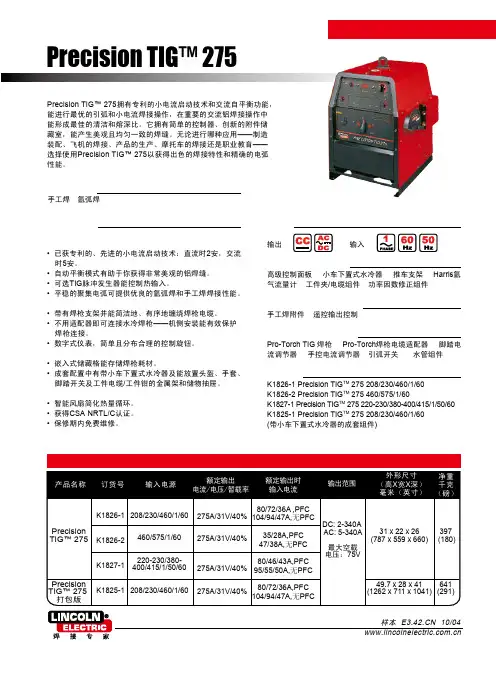
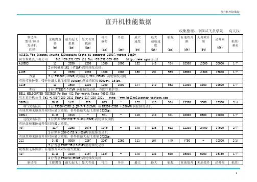

国别型号名称口径(mm)阿根廷FARA83式 5.56阿根廷FN7.62奥地利施泰尔AUG 5.56奥地利SSG69式7.62奥地利AMR5075式15澳大利亚L1A1-F1式7.62比利时FN CAL 5.56比利时FN FNC 5.56比利时FN FAL 50-64式7.62比利时FN30-11式7.62德国G11K3式 4.7德国HK33E式 5.56德国HKG41式 5.56德国G3式7.62德国G8式7.62德国毛瑟86SR式7.62德国MP43/44式7.92法国FAMAS 5.56法国MAS49/56式7.5法国FR-F1式7.5/7.62芬兰瓦尔梅特M76W式7.62/5.56芬兰瓦尔梅特M90式7.62/5.56芬兰瓦尔梅特M78式7.62韩国K1A式 5.56韩国K2式 5.56加拿大C8式 5.56加拿大C1A1式7.62美国可控点射步枪 4.32美国AAI先进战斗步枪 5.56美国M16式 5.56美国M16A2式 5.56美国TRW低维修率步枪 5.56美国柯尔特M231式 5.56美国柯尔特先进战斗步枪 5.56美国鲁格Mini-14式 5.56美国M4式 5.56美国M14式7.62美国AR-10式7.62美国M1式7.62美国M24式7.62美国M40A1式7.62美国麦克米伦M86式7.62美国佩里格林50/12式12.7美国巴雷特M82A1式12.7美国波扎P50式12.7美国麦克米伦M88式12.7美国XM70式南非R4式 5.56南非R5式 5.56前捷克斯洛伐克54式7.62前捷克斯洛伐克58式7.62前南斯拉夫M80式 5.56前南斯拉夫M59/66A1式7.62前南斯拉夫M70B1式7.62前南斯拉夫M77B1式7.62前南斯拉夫M76式7.92前苏联AK-74式 5.45前苏联西蒙诺夫7.62前苏联AK-47式7.62前苏联AKM7.62前苏联德拉戈诺夫SVD7.62俄罗斯A-91式 5.45俄罗斯A-91式 5.56俄罗斯A-91式7.62俄罗斯A-91式9俄罗斯卡拉什尼科夫AK-101式 5.56俄罗斯卡拉什尼科夫AK-103式7.62俄罗斯卡拉什尼科夫AK-102式 5.56俄罗斯卡拉什尼科夫AK-104式7.62俄罗斯卡拉什尼科夫AK-105式 5.45俄罗斯德拉戈诺夫SVDS7.62俄罗斯AS9日本89式 5.56日本64式7.62瑞典FFV890C式 5.56瑞典AK5式 5.56瑞典MKS 5.56瑞士SIG SG540式 5.56瑞士SIG SG550式 5.56瑞士M31/55式7.5瑞士SIG SG510-4式7.62瑞士SSG2000式7.62瑞士SSG3000式7.62西班牙L式 5.56西班牙赛特迈A7.62新加坡SAR80式 5.56新加坡SR88式 5.56匈牙利NGM 5.56匈牙利AMD-65式7.62匈牙利猎豹M1式12.7以色列加利尔(AR) 5.56以色列加利尔7.62意大利AR70式 5.56意大利AR70/90式 5.56意大利BM59式7.62意大利伯莱塔7.62印度INSAS 5.56英国L85A1式 5.56英国恩菲尔德L1A1式7.62英国恩菲尔德L39A1式7.62英国恩菲尔德L42A1式7.62英国BGR7.62英国帕克-黑尔M82式7.62英国帕克-黑尔M85式7.62英国帕克-黑尔M87式7.62英国隐藏式PM7.62英国德莱尔M3式11.43初速(m/s)表尺射程(m)965~100583097086015001500~2000820970965(M193)915(SS109)400840850600930920910780~800800650960825852720/960约800720(7.62×39,mm枪弹)830(7.62 ×51,mm枪弹)820960(M193式枪弹)920(SS109式枪弹)600920840600112014021000948(SS109式枪弹)991(M193式枪弹)986914948(M855枪弹)884(双头弹)1005906(SS109式枪弹)921(M193式枪弹)853760607792777853(M33式普通弹)1418980920795710920735720840720900735710715830670250680250570250270200910100071510008505006705008405008101200295300(夜视瞄准具)920700(减装药弹),800(全装药弹)860500930975980995780800790750875760970970(M193式枪弹)900700870950815(FN比赛弹),780(M118式比赛弹)950950823885940838841838860860314~330260(普通弹)328(高速增压弹)有效射程(m)理论射速(发/min)战斗射速(发/min)750~8008006508001000600700300625~750650650~700300600(连发)、2000(3发点射)400750850400500~60080050050030090060015~2080010 300~400600~750300~400600~750700650700~900900400700~950600(SS109式枪弹)700~9004604503001100~130050~60 325(双头弹)300600(最大)700~1000700700~750700300650650120040080040050030~40400620~66040600600100040065040035~403006006008001300(最大)700~900700~900700~900700~90060040(单发)100(连发)60040(单发)100(连发)60040(单发)100(连发)60040(单发)100(连发)60040(单发)100(连发)650~850400500650650400700~1100650~80070060012600600~750600550400600~800400650~8509003006001200(对人员)、2000(对轻型装甲车)500600650650600750610~775 600(采用氚光瞄准镜)300300(11.43mm柯尔特自动手枪弹)自动方式供弹方式容弹量(发)全枪长mm导气式弹匣301000(枪托打开)745(枪托折叠)导气式弹匣201090导气式弹匣30或42790手动旋转式弹仓51140枪管长后坐式弹匣5导气式弹匣201066导气式弹匣20980导气式弹匣30997(枪托打开)766(枪托折叠)导气式弹匣10、201095(枪托打开)845(枪托折叠)手动弹仓51117导气式弹匣45750半自由枪机式弹匣25940(枪托拉出)735(枪托缩回)半自由枪机式弹匣30997半自由枪机式弹匣201025半自由枪机式弹匣、弹鼓20(弹匣)、50(弹鼓)1030非自动双排式弹仓91210导气式弹匣30940半自由枪机式弹匣25757导气管式弹匣101100手动弹匣101138导气式弹匣15、20、30950(枪托打开)710(枪托折叠)导气式弹匣30930(枪托打开) 675(枪托折叠)导气式弹匣、弹鼓15和30(弹匣)75(弹鼓)1060导气管式弹匣30830(枪托拉出)645(枪托缩回)导气式弹匣30990(枪托打开) 730(枪托折叠)导气管式弹匣30840(枪托打开)760(枪托折叠)导气式弹匣201136导气管式弹匣30875导气式弹匣301016导气管式弹匣20、30990导气管式弹匣20、301000导气式弹匣30872(含消焰器)导气管式弹匣30820(枪托拉出)710(枪托缩回)导气式弹匣301031(枪托拉出)931(枪托缩回)导气式弹匣5、20或30946导气式弹匣20或30840(枪托拉出)760(枪托缩回)导气式弹匣201120导气管式弹匣201016导气式弹匣15或30904非自动弹仓51092~1161非自动弹仓51117非自动弹仓41107导气式弹匣101410枪管短后坐式弹匣101448导气式弹匣51299非自动弹仓51295活塞火帽式弹匣501076导气式弹匣35或501005(枪托打开)740(枪托折叠)导气式弹匣35或50877(枪托打开) 615(枪托折叠)非自动弹仓101148导气式弹匣30820(枪托打开)635(枪托折叠)导气式弹匣30990导气式弹仓101320(刺刀打开)1120(刺刀折叠)导气式弹匣30900导气式弹匣20990导气式弹匣101135导气式弹匣30930导气式弹仓101021导气式弹匣30870(枪托打开)645(枪托折叠)876导气式弹匣101225导气式弹匣20604(枪托打开)导气式弹匣20604(枪托打开)导气式弹匣20604(枪托打开)导气式弹匣20604(枪托打开)弹匣30943(枪托打开)700(枪托折叠)弹匣30943(枪托打开)700(枪托折叠)弹匣30824(枪托打开)586(枪托折叠)弹匣30824(枪托打开)586(枪托折叠)弹匣30824(枪托打开)586(枪托折叠)弹匣10、151135(枪托打开)875(枪托折叠)导气式弹匣20878(枪托打开)615(枪托折叠)导气式弹匣20、30916(枪托打开)670(枪托折叠)导气式弹匣20990导气式弹匣35860(枪托打开) 625(枪托折叠)导气式弹匣301008(枪托打开)753(枪托折叠)导气式弹匣30868(枪托打开) 634(枪托折叠)导气式弹匣20、30950导气式弹匣20、30998(枪托打开)772(枪托折叠)非自动弹仓61210半自由枪机式弹匣201016非自动弹仓41210非自动弹仓51180半自由枪机式弹匣20、30925半自由枪机式弹匣20、30970导气式弹匣20、30970(枪托打开)738(枪托折叠)导气式弹匣20、30970导气式弹匣30935导气式弧形弹匣30851(枪托打开)648(枪托折叠)非自动1540导气式弹匣35、50979(枪托打开) 742(枪托折叠)导气式弹匣201115(枪托打开)840(枪托折叠)导气式弹匣30955导气式弹匣30998导气式弹匣201095非自动弹仓51165导气式弹匣20、30990(固定枪托)导气式弹匣30785导气式弹匣201143手动弹仓101180手动弹仓101181非自动弹匣5~201200非自动弹仓41162非自动弹匣101150~1210非自动弹仓51143非自动弹匣10×2、201250非自动弹仓4960枪管长mm全枪质量kg452 3.95(不含弹匣)533 4.6(不含弹匣)508 3.6(不含弹匣)650 3.9(不含弹匣)1200约20(不含弹匣)533 4.43(不含弹匣) 467(不含消焰器)3(不含弹匣和背带)449 3.8(不含弹匣)533 3.9(不含弹匣或刺刀)502 4.85(不含弹匣) 540(不含弹膛) 3.65(不含弹匣)390 3.98(不含弹匣)450 4.1(不含弹匣)450 4.4(不含弹匣) 450(不含制退器)8.15(不含弹匣、含两脚架) 730(含枪口制退器) 4.9(不含瞄准镜)419 5.1488 3.61(不含弹匣)526 3.9(不含弹匣)552 5.2( 不含弹匣)420 3.6(不含弹匣)416 3.85(不含弹匣)526 4.7(不含弹匣)263(不含枪口制退/补偿器) 2.88(不含枪弹)465(不含枪口制退/补偿器) 3.26(不含弹匣)370 2.7(不含弹匣)533 4.254.54(含空弹匣)3.53(不含弹匣)508(不含消焰器) 3.1(不含背带和擦拭工具)510(不含消焰器) 3.4(不含弹匣)493(不含消焰器) 3.3(不含弹匣)368 3.9(不含弹匣)3.306(不含弹匣和瞄准镜)470 2.9(不含弹匣)368 2.54(不含弹匣)559 5.1(含实弹匣)508 3.4(不含弹匣)458 2.36(含空弹匣)610 5.27(不含枪弹)610 6.57(不含枪弹、含瞄准镜)610 5.4(不含枪弹,含瞄准镜)73715.2(含空弹匣)73712.973713.6730约12(不含枪弹)508460 4.3(不含弹匣)332 3.7(不含弹匣)700 4.38(不含枪弹含瞄准镜)401 3.14( 含金属托不含弹匣)460 3.5(不含弹匣)520 4.1(不含弹匣)415 3.7(含空弹匣)500 4.8(含空弹匣)550 4.2(不含弹匣)400 3.3(含空弹匣)520 3.85(不含枪弹)415 4.3(不含弹匣)3.15(不含弹匣)622 4.3(含瞄准镜)1.75(不含弹匣)1.75(不含弹匣)1.75(不含弹匣)1.75(不含弹匣)415 3.4(不含弹匣)415 3.3(不含弹匣)3143(不含弹匣)314 2.9(不含弹匣)3143(不含弹匣)4.68(含光学瞄准镜和空弹匣)2.5(不含弹匣与瞄准具)420 3.5(不含弹匣)450 4.4(不含弹匣)340 3.5(不含弹匣)450 3.9(不含弹匣)467 2.75(含空弹匣)460(不含消焰器) 3.26(不含弹匣)528 4.1(含空弹匣和两脚架)655 5.53(不含枪弹和瞄准镜)505 4.25(不含弹匣)610 6.6(含弹匣和瞄准镜)610(不含枪口装置) 5.4(含空弹匣,瞄准镜) 400 3.4(不含弹匣)435 4.25(不含弹匣)459 3.7(不含弹匣)459 3.66(不含弹匣)412 3.18(不含弹匣)318(不含消焰器) 3.27110015460 3.95(不含弹匣,两脚架和提把) 508(不含枪口制退器) 6.4(不含弹匣,含两脚架和背带)$450 3.8(含空弹匣)450 3.99(不含弹匣)490 4.6(不含弹匣)586 5.55( 不含枪弹)464 3.2(不含弹匣)518 3.8(不含弹匣和光学瞄准镜) 554 4.3(不含弹匣)700 4.42(不含枪弹)699 4.43(不含枪弹)700 6.6(含瞄准镜和两脚架) 660 4.8(不含枪弹)700 5.7(不含枪弹,含光学瞄准镜) 660 4.55(不含枪弹)655 6.5210 3.7(不含瞄准镜)使用枪弹M193式或SS109式5.56mm枪弹北约7.62mm枪弹SS109式5.56mm枪弹北约7.62mm枪弹、0.243in温彻斯特枪弹15mm专用枪弹北约7.62mm枪弹M193式5.56mm枪弹SS109式或M193式5.56mm枪弹北约7.62mm 枪弹北约7.62mm枪弹、0.308in温彻斯特枪弹DM11式4.73mm无壳弹5.56mm枪弹北约5.56mm枪弹7.62mm枪弹7.62mm枪弹7.62mm枪弹(0.308in温彻斯特枪弹)7.92mm枪弹M193式5.56mm枪弹、北约SS109式5.56mm枪弹M1929式7.5mm枪弹7.5mm枪弹、北约7.62mm枪弹7.62mm或5.56mm枪弹7.62mm或5.56mm枪弹7.62×39,mm、7.62×51,mm枪弹5.56mm枪弹M193式或SS109式5.56mm枪弹M193式或SS109式5.56mm枪弹北约7.62mm枪弹4.32mm枪弹5.56mm次口径箭形弹M193式5.56mm枪弹SS109 式及其他5.56mm枪弹M193式5.56mm枪弹M193式5.56mm枪弹M855式5.56mm枪弹及5.56mm双头弹M193式和SS109式5.56mm枪弹SS109式和M193式5.56mm枪弹北约7.62mm枪弹北约7.62mm枪弹M1式7.62mm卡宾枪枪弹M118式7.62mm特种弹头比赛弹北约7.62mm枪弹#*[-4]0.30-06斯普林菲尔德枪弹、0.308in枪弹、7.62mm温彻斯#*[4] 特马格努姆枪弹12.7mm勃朗宁机枪弹、前苏联12.7mm机枪弹12.7mm勃朗宁机枪弹12.7mm勃朗宁机枪弹12.7mm勃朗宁机枪弹XM645式箭形弹5.56mm枪弹5.56mm枪弹7.62mm枪弹M43式7.62mm中间型枪弹M193或SS109式5.56mm枪弹M43式7.62mm枪弹M43式7.62mm枪弹北约7.62mm枪弹7.92mm毛瑟枪弹5.45mm枪弹M43式7.62mm枪弹M43式7.62mm枪弹M43式7.62mm枪弹7.62mm枪弹M1974式5.45mm枪弹北约5.56mm枪弹M1943式7.62mm枪弹СП-5式和СП-6式9mm枪弹北约5.56mm枪弹M1943式7.62mm枪弹北约5.56mm枪弹M1943式7.62mm枪弹5.45mm枪弹7.62mm枪弹9mm枪弹北约5.56mm枪弹7.62mm减装药弹或全装药弹5.56mm枪弹北约5.56mm枪弹M193式5.56mm枪弹5.56mm枪弹北约5.56mm枪弹M11式7.5mm枪弹北约7.62mm枪弹北约7.62mm枪弹北约7.62mm枪弹SS109式5.56mm枪弹7.62mm减装药枪弹M196式和M193式5.56mm枪弹M193式或SS109式5.56mm枪弹M193式或SS109式5.56mm枪弹M43式7.62mm中间型枪弹12.7mm穿甲燃烧弹、穿甲燃烧曳光弹5.56mm枪弹北约7.62mm枪弹M193式或SS109式5.56mm枪弹北约5.56mm枪弹北约7.62mm枪弹北约7.62mm枪弹SS109式5.56mm枪弹北约5.56mm枪弹北约7.62mm枪弹北约7.62mm枪弹北约7.62mm枪弹#*[-5]北约7.62mm枪弹、0.243in温彻斯特枪弹、0.300in温彻斯#*[5]特马格努姆枪弹北约7.62mm枪弹北约7.62mm枪弹#*[-5]北约7.62mm枪弹、0.243in温彻斯特枪弹、6.5mm枪弹、0.30-06 枪弹、0.300in温彻斯特马格努姆枪弹#*[5]7.62mm亚音速枪弹11.43mm柯尔特自动手枪弹备注装备装备装备装备研制装备装备生产装备装备少量试装备装备装备装备生产生产淘汰生产停产装备装备装备装备装备生产装备装备停止发展停止发展装备装备停止发展装备停止发展生产装备撤装未投产停产生产生产研制研制生产研制研制停止发展生产生产撤装装备出口生产装备生产生产生产撤装撤装生产装备生产生产生产生产生产生产生产生产生产生产生产装备装备停止发展装备停止发展装备装备停产装备装备研制装备撤装装备生产生产装备生产生产装备装备装备装备装备装备装备装备停止生产装备生产停止生产装备装备装备生产。
五种AIP潜艇谁更有前途自我鉴定生活负载的能量需要,充其量还只是减少通气管航行时间,降低暴露率。
这主要是由于常规潜艇空间小,AIP系统的燃料和氧化剂携带量有限。
当前这几种AIP的输出功率,斯特林发动机约为240千瓦,燃料电池约为300千瓦,闭式循环汽轮机约为200千瓦左右,闭式循环柴油发动机可达到400千瓦。
这种功率水平是什么概念只相当于常规潜艇上装备的标准柴油机电机推进系统最大输出功率的10%。
斯特林发动机是瑞典于1988年出台的,到现在有多少改进郭:目前,装V4-275R斯特林发动机的潜艇除“哥特兰”级3艘外,还有瑞典在役的“西约特兰”级和日本“苍龙”级,都是MK2型。
瑞典对MK2型斯特林发动机的改进很缓慢,后续型是MK3。
MK3主要在发动机效率、输出功率、水下运行深度、隐蔽性等方面有所改进。
“哥特兰”级水下排水量1490吨,用柴油机推进时,水面最高航速11节,短时间水下最高航速20节。
它装的2台V4-275R斯特林发动机单台最大输出功率75千瓦,持续功率为65千瓦。
两台总共可持续发出130千瓦的功率,主要用于艇上生活设施,如照明、烹调、加热器以及电子设备等,这方面大约要消耗80千瓦,剩余的50千瓦被用于水下航行,可在5节速度下水下连续航行14天。
“哥特兰”级最初曾考虑装3台斯特林发动机,后因经费不足等原因,第3台没装,但艇上已预留了空间及配套设备。
如果装第3台及其液氧燃料,水下航速还会提高,续航力也比装2台时要提高1/3。
斯特林发动机的原理是将液氧罐中的液态氧气化,和柴油在位于斯特林发动机上部的燃烧室内混合燃烧,产生的热量传递给工作气体氦气。
氦气在被加热体积膨胀及被冷却体积收缩过程中推动活塞运动。
活塞再带动曲柄转动,曲柄提供机械能量来驱动发电机,电流供给电机以带动螺旋桨。
斯特林发动机的废气排放口是经过专门设计的,尽可能保证废气气泡不被敌方声呐探测到。
燃烧系统也经过了特别设计,可保证燃料完全燃烧,大大减少了废气中其它气体的含量。
1 2 3 4 5 6 7 8 9Specification StatusChange Made atBPS4000 revRev revDate Attachments Org Title supersededBy specialNotes latestSupersedingDoc reviewBy 160-006AM040322BHTI Alternate Materials List M&P 299-947-100-690115BHTI Procurement Specification for Epoxy Adhesive, Heat Resistant M&P 299-947-320-820507BHTIAdhesive Film and Primer System, Intermedite Cure Temperature (260-290º F) ServiceTemerature 67-225º F)M&P 68A900000G011101BAC Finish Spec:F-15M&P 74A900000E990308BAC Finish Specification for F18 Aircraft M&P 74A900004L010501BAC Ctrl:Fract Crit Parts, F-18M&P 74A901001F981208BAC Std Finish Codes:F-18 A\C M&P 901-947-002CA D950510BHTI Finish Specification for the V-22 Aircraft (Bell Boeing) Model 901) EMD Aircraft M&P10 11 12 13 14 15 16 17 18 19 20 21 22 23 24 25 26A-A-208B951120Notice 2 Notice 3FED Ink, Marking, Stencil, Opaque M&P A-A-2962Cancelled no s/s spec A980810canc notice 2-060106FED Commercial Item Description Enamel, Alkyd, Exterior, Solvent Based, Low Voc ok to use canc spec M&P A-A-3097BK-970506Notice 3FEDCommercial Item Description Adhesives, Cyanoacrylate, Rapid Room Temperature-Curing,SolventlessM&P A-A-3165CA A071116Notice 2FED Lacquer, Gloss, for A/C Use M&P A-A-52080B980523Notice 1FED Tape, Lacing, and Tying, Nylon M&P A-A-52081B980523FED Tape, Lacing, and Tying, Polyester M&P A-A-52082CE C070904Notice 1FED Tape, Lacing and Tying, TFE-Fluorocarbon M&P A-A-52083BJ C040223FED Tape, Lacing, and Tying, Glass M&P A-A-52084B980523Notice 1FED Tape, Lacing and Tying, Aramid M&P A-A-55829-970204Notice 1DLA Acetic Acid, Glacial, Technical M&P A-A-56032CN D030521Notice 1FED Commercial Item Description (CIDS) Ink, Marking, Epoxy Base M&P A-A-59126-970926FED Terminals, Feedthru (Insulated) and Terminals, Stud (Insulated and Noninsulated)ENG A-A-59132CR A100607Validation Notice 1DLA Amyl Acetate, Technical M&P A-A-59135CR-971028FED Commercial Item Description Packaging Material, Sheet M&P A-A-59136CR-971028FED Cushioning Material, Packaging, Closed Cell Foam Plank M&P A-A-59178CL A041012USGOVT Nipple, Electrical Terminal ENG A-A-59503CG B081020FED Commercial Item Description Nitrogen, Technical M&P A A59551Wire Electrical Copper(Uninsulated)27 28 29 30 31 32 33 34 35 36 37 38 39 40 41 42 43 44A-A-59551CP A091022USGOVT Wire, Electrical, Copper (Uninsulated) M&P A-A-59569CK C090122DLA Qualification Sampling and Testing of Steels for Transverse Tensile Properties ENG A-A-59588BK A050707FED Commercial Item Description Rubber, Silicone M&P A-A-59877CT-100909FED Comemrcial Item Description Insulating Compound, Electrical, Embedding M&P AIR4127CG - 071101SAE Steel: Chemical Composition and Hardenability M&P AISI-1010Unavailable-AISI Low Carb Stl Unavailable M&P AISI-50100Unavailable-AISI Bearing Stl Unavailable M&P AISI-52100Unavailable-AISI Bearing Stl Unavailable M&P AISI-B-1112Unavailable-AISI Low Carb Free Mach Stl Unavailable M&P AISI-C-1212Unavailable-AISI Matl Spec, Stl Unavailable M&P AISI-C-1213Unavailable-AISI Low Carb Free Mach Stl Unavailable M&P AISI-C-1214Unavailable-AISI Matl Spec, Stl Unavailable M&P AMS 2175CR A100601SAE Castings, Classification and Inspection of M&PAMS 2201Cancelled CN Can940901SAETolerances Aluminum and Aluminum Alloy Bar, Rod, Wire, and Forging Stock Rolled or Cold-FinishedANSI H35.2M&PAMS 2221G060201SAE Tolerances, Copper and Copper Alloy Bars and Rods M&P AMS 2222BG J060201SAE Tolerances, Copper and Copper Alloy Sheet, Strip, and Plate M&P AMS 2223BF H060201SAE Tolerances Copper and Copper Alloy Seamless Tubing M&P AMS 2224G060201SAE Tolerances Copper and Copper Alloy Wire M&P AMS2241Tolerances,Corrosion and Heat-Resistant Steel,Iron Alloy,Titanium,and Titanium Alloy Bars and45 46 47 4849 50 51 52 53 54 55 56 57 58AMS 2241CN R070701SAETolerances, Corrosion and Heat Resistant Steel, Iron Alloy, Titanium, and Titanium Alloy Bars andWireM&P AMS 2242CC G080604SAETolerances Corrosion and Heat Resistant Steel, Iron Alloy, Titanium and Titanium Alloy Sheet,Strip and PlateM&P AMS 2243BJ H060501SAE Tolerances Corrosion and Heat-Resistant Steel Tubing M&P AMS 2248CN F060501SAEChemical Check Analysis Limits Corrosion and Heat-Resistant Steels and Alloys, Maraging andother Highly-Alloyed Steels, and Iron AlloysM&PAMS 2249CN G090701SAEChemical Check Analysis Limits Titanium and Titanium AlloysM&PAMS 2259CN E071201SAE Chemical Check Analysis Limits Wrought Low-Alloy and Carbon Steels M&P AMS 2269CN F060501SAE Chemical Check Analysis Limits Nickel, Nickel Alloys, and Cobalt Alloys M&P AMS 2300BF K031001SAE Steel Cleanliness, Premium Aircraft-Quality Magnetic Particle Inspection Procedure M&P AMS 2301CT K100801SAE Steel Cleanliness, Aircraft Quality Magnetic Particle Inspection Procedure M&P AMS 2303CT F100801SAESteel Cleanliness, Aircraft Quality, Martensitic Corrosion Resistant Steels Magnetic ParticleInspection ProcedureM&P AMS 2304CN A060301SAE Steel Cleanliness, Special Aircraft-Quality Magnetic Particle Inspection Procedure M&P AMS 2310BE F060201SAE Qualification Sampling and Testing of Steels for Transverse Tensile Properties M&P AMS 2315CN F080101SAE Determination of Delta Ferrite Content M&PAMS 2350Cancelled no s/s spec CN BA891001SAEStandards and Test Methodsok to use canc spec M&P1Specification Status Change Made atBPS4000 revRev revDate Attachments Org Title supersededBy specialNotes latestSupersedingDoc reviewBy59 60 61 62 63 64AMS 2355CN J090701SAEQuality Assurance Sampling and Testing Aluminum Alloys and Magnesium Alloy WroughtProducts (Except Forging Stock), and Rolled, Forged, or Flash Welding RingsM&P AMS 2360CN D070701SAE Room Temperature Tensile Properties of Castings M&P AMS 2370CN J071101SAEQuality Assurance Sampling and Testing Carbon and Low-Alloy Steel Wrought Products andForging StockM&P AMS 2371CN H071101SAEQuality Assurance Sampling and Testing Corrosion and Heat-Resistant Steels and Alloys WroughtProducts and Forging StockM&P AMS 2372CN E070601SAE Quality Assurance Sampling and Testing Carbon and Low-Alloy Steel Forgings M&P AMS 2375CN D070601SAE Control of Forgings Requiring First Article Approval M&PA l d C t l f P i Q lit Tit i All65 66 67 68 69 70 71 72 73 74 75 76 77 78 79 80 81 82AMS 2380CN F080601SAE Approval and Control of Premium-Quality Titanium Alloys M&P AMS 2400BV W070701SAE Plating, Cadmium M&P AMS 2401CN H071101SAE Plating, Cadmium Low Hydrogen Content Deposit M&P AMS 2403BM L041001SAE Plating, Nickel General Purpose M&P AMS 2404CH F081201SAE Plating, Electroless Nickel M&P AMS 2405Noncurrent CN C841010SAE Electroless Nickel Plate, Low Phosphorous M&P AMS 2406BV L070501SAE Plating, Chromium Hard Deposit M&P AMS 2408CF J081101SAE Plating, Tin M&P AMS 2410CR K100401SAE Plating, Silver Nickel Strike, High Bake M&P AMS 2411CB G080201SAE Plating, Silver for High Temperature Applications M&P AMS 2412CN J091201SAE Plating, Silver Copper Strike, Low Bake M&P AMS 2416K040301SAE Plating, Nickel-Cadmium Diffused M&P AMS 2417G040701SAE Plating, Zinc-Nickel Alloy M&P AMS 2418G060101SAE Plating, Copper M&P AMS 2419BM C030501SAE Plating, Cadmium-Titanium M&P AMS 2420D021201SAE Plating of Aluminum for Solderability Zinc Immersion Pre-Treatment Process M&PAMS 2423**See special notes CE D020401SAE Plating, Nickel Hard DepositContinue to use AMS-QQ-N-290 for Class2 NickelM&PAMS 2424CR F100401SAE NI Plate, Low Stressed Deposit M&P AMS2426D Coating Cadmium Vacuum Deposition83 84 85 86 87 88 89 90 91 92 93 94AMS 2426BT020901SAE Coating, Cadmium Vacuum Deposition M&P AMS 2429C011101SAE Bronze Plate Masking M&P AMS 2430CN R100101SAE Shot Peening, Automatic M&P AMS 2433C041001SAE Plating, Nickel-Thallium-Boron or Nickel-Boron M&P AMS 2434CN C060501SAE Plating, Tin-Zinc Alloy M&P AMS 2435Noncurrent CN G070601SAE Coating, Tungsten Carbide-Cobalt Coating, Detonation Process M&P AMS 2437BN C710111SAE Coating, Plasma Spray Deposition M&P AMS 2438CL D090701SAE Plating, Chromium Thin, Hard, Dense Deposit M&P AMS 2444BM A001201SAE Coating, Titanium Nitride Physical Vapor Deposition M&P AMS 2451BN B060501SAE Plating, Brush General Requirements M&PAMS 2460See special notes CA-070701SAE Plating, ChromiumIf dwg requires chrome plate per AMS-QQ-C-320 then stress relief and embritlmnt(emb) bake relief per BPS4620. If dwg req'schrome plate per AMS 2460 then stressrelief and bake relief per AMS 2460 unlessthe dwg specifically req's BPS 4620M&PAMS 2468Cancelled CN G981001SAE Hard Anodic Coating Treatment of Aluminum Alloys AMS 2469M&P AMS 2469CG H080701SAEHard Anodic Coating Treatment of Aluminum and Aluminum Alloys Processing and PerformanceRequirementsM&P95 96 97 98 99 100 101 102 103 104 105 106 107 108 109 110 111qAMS 2470CN M070401SAE Anodic Treatment of Aluminum Alloys Chromic Acid Process M&P AMS 2471CN G081201SAE Anodic Treatment of Aluminum Alloys Sulfuric Acid Process, Undyed Coating M&P AMS 2481CP J100201SAE Phosphate Treatment Antichafing M&PAMS 2482CN D100101SAEHard Anodic Coating on Aluminum Alloys Polytetrafluoroethylene (PTFE)-Impregnated orCodepositedM&PAMS 2485BY K080101SAE Coating, Black Oxide M&P AMS 2486CR E100501SAE Conversion Coating of Titanium Alloys Fluoride-Phosphate Type M&P AMS 2487CN A000301SAE Anodic Treatment of Titanium and Titanium Alloys Solution pH 12.4 Maximum M&P AMS 2488D000606SAE Anodic Tr:Ti,Ti Alys M&P AMS 2515BM E900101SAE Polytetrafluoroethylene (PTFE) Resin Coating Low Build, 370 to 400 °C (698 to 752 °F) Fusion M&P AMS 2516BM D900101SAE Polytetrafluoroethylene (PTFE) Resin Coating High Build, 370 to 400 °C (698 to 752 °F) Fusion M&P AMS 2525C030401SAE Graphite Coating, Thin Lubricating Film Impingement Applied M&P AMS 2526BW C071001SAE Molybdenum Disulfide Coating, Thin Lubricating Film Impingement Applied M&P AMS 2615BM F060901SAE Pressure Testing Hydraulic Pressure as Specified M&P AMS 2630CR C100101SAE Inspection, Ultrasonic Product Over 0.5 Inch (12.7 mm) Thick M&P AMS 2631CN C090701SAE Ultrasonic Inspection Titanium and Titanium Alloy Bar and Billet M&P AMS 2632BN A950301SAEInspection, Ultrasonic, Of Thin Materials 0.50 Inch (12.7 mm) and Under in Cross-SectionalThicknessM&P1Specification Status Change Made atBPS4000 revRev revDate Attachments Org Title supersededBy specialNotes latestSupersedingDoc reviewBy112 113 114 115 116 117 118 119 120AMS 2635Cancelled Can810701SAE Radiographic Insp ASTM E1742M&P AMS 2640Cancelled CH Can960401SAE Magnetic Particle Inspection ASTM E1444M&P AMS 2645Cancelled CH Can950201SAE Fluorescent Penetrant Inspection ASTM E1417M&P AMS 2649CA C080101SAE Etch Inspection of High Strength Steel Parts M&P AMS 2658CN C091001SAE Hardness and Conductivity Inspection of Wrought Aluminum Alloy Parts M&P AMS 2664CH F950701SAE Brazing, Silver For Use Up to 800 °F (427 °C)M&P AMS 2665G030101SAE Brazing, Silver for Use up to 400 °F (204 °C)M&P AMS 2666Cancelled Can840101SAE Ag Braz,High Temp AMS 2664M&P AMS 2670BK J060601SAE Brazing, Copper M&P121 122 123 124 125 126 127 128 129 130 131 132 133 134135AMS 2671Cancelled CH Can920101SAE Copper Brazing Corrosion and Heat Resistant Steels and Alloys AMS 2670M&P AMS 2672BM F010301SAE Brazing, Aluminum Torch or Furnace M&P AMS 2673BM D010301SAE Brazing, Aluminum and Aluminum Alloys Molten Flux (Dip)M&P AMS 2675G020501SAE Brazing, Nickel Alloy Filler Metal M&P AMS 2680C010601SAE Electron--Beam Welding for Fatigue Critical Applications M&P AMS 2681B000301SAE Electron Beam Welding M&P AMS 2685Noncurrent CP E071001SAE Welding, Tungsten Arc, Inert Gas GTAW Method M&P AMS 2689Noncurrent CH A980201SAE Fusion Welding Titanium and Titanium Alloys M&P AMS 2694BR B070201SAE In-Process Welding of Castings M&PAMS 2700CF C081101SAE Passivation of Corrosion Resistant SteelsIf no Method & Type are specified must useMethod 1, Type 2,6,7 or 8 depending on thebase material. All acceptance testing shallbe per Class 4.M&PAMS 2728BM A050301SAE Heat Treatment of Wrought Copper Beryllium Alloy Parts M&P AMS 2745CJ A071201SAE Induction Hardening of Steel Parts M&P AMS 2750BN D050901SAE M&P AMS 2753CF C080801SAE Liquid Salt Bath Ferritic Nitrocarburizing Non-Cyanide Bath M&P AMS 2755Cancelled CM Can090701SAE Nitriding, Molten Salt BathProcess not available, consider AMS 2753as replacementM&P136137 138 139140 141 142 143 144 145as replacement.AMS 2759CE E081001SAE Heat Treatment of Steel Parts General Requirements M&P AMS 2759/1CJ E090201SAEHeat Treatment of Carbon & Low-Alloy Steel Parts Minimum Tensile Strength Below 220 ksi (1517Mpa)Supersedes MIL-H-6875 for carbon & low-alloy steels below 220 KSIM&P AMS 2759/10CN A060601SAE Automated Gaseous Nitriding Controlled by Nitriding Potential M&P AMS 2759/11BW-050401SAE Stress Relief of Steel Parts M&P AMS 2759/2CR F100501SAE Heat Treatment of Low-Alloy Steel Parts Minimum Tensile Strength 220 ksi (1517 Mpa) and HigherSupersedes MIL-H-6875 for low-alloysteels, 220 KSI & higher M&P AMS 2759/3CE E080801SAE Heat Treatment Precipitation-Hardening Corrosion-Resistant & Maraging Steel PartsSupersedes MIL-H-6875 for precipitationhardening & maraging steelM&P AMS 2759/4CA C080301SAE Heat Treatment Austenitic Corrosion-Resistant Steel PartsSupersedes MIL-H-6875 for austenticsteelsM&P AMS 2759/5D040601SAE Heat Treatment Martensitic Corrosion Resistant Steel PartsSupersedes MIL-H-6875 for martensiticsteelsM&P AMS 2759/6BM B051101SAE Gas Nitriding & Heat Treatment of Low - Alloy Steel Parts Use Standard Drawing Notes per BDS2240M&P AMS 2759/7CT B100501SAE Carburizing and Heat Treatment of Carburizing Grade Steel Parts M&P1. Infrared pyrometry may be used to146 147 148 149 150 151 152 153 154 155 156AMS 2759/8CG A070601See Special Notes SAE Ion Nitridingmeasure temperature. 2. The nitridingtemperature may be less than 50 degreesbelow the tempering or aging temperatureprovided that the core hardness is notreduced. 3. For small loads, a minimum oftwo acceptance testing specimens may beused in lieu of four, provided that at leastone specimen is placed in each layer.M&P AMS 2759/9CL D090501SAE Hydrogen Embrittlement Relief (Baking of Steel Parts)Supersedes MIL-H-6875 for stress relievingsteelsM&P AMS 2762Noncurrent CP B020101SAE Carburizing Carbon and Low-Alloy Steel Parts M&P AMS 2768CR C100701SAE Heat Treatment of Magnesium Alloy Castings M&P AMS 2770BJ H060801SAE Heat Treatment of Wrought Aluminum Alloy Parts M&P AMS 2771C040701SAE Heat Treatment of Aluminum Alloy Castings M&P AMS 2772BY E080201SAE Heat Treatment of Aluminum Alloy Raw Materials M&P AMS 2774CG B080801SAE Heat Treatment Wrought Nickel Alloy and Cobalt Alloy Parts M&P AMS 2800CN D060801SAE Identification Finished Parts M&P AMS 2801B030301SAE Heat Treatment of Titanium Alloy Parts M&P AMS 2807CF B080201SAEIdentification Carbon and Low-Alloy Steels, Corrosion and Heat-Resistant Steels and Alloys Sheet,Strip, Plate and Aircraft TubingM&P1Specification Status Change Made atBPS4000 revRev revDate Attachments Org Title supersededBy specialNotes latestSupersedingDoc reviewBy157 158 159 160161162AMS 3025CN C090901SAE Polyalkylene Glycol Heat Treat Quenchant M&P AMS 3106Cancelled Can830401SAE Primer, Adhesive,Corr Inhib AMS 3107M&P AMS 3107A910401SAE Primer, Adhesive,Corr-Inhibiting M&P AMS 3195E920101SAE Silicone Rubber Sponge M&PAMS 3216G050901SAE Fluorocarbon (FKM) Rubber High-Temperature - Fluid Resistant Low Compression Set 70 to 80M&P AMS 3218C050901SAE Fluorocarbon (FKM) Rubber High-Temperature - Fluid Resistant Low Compression Set 85 to 95M&P AMS3276Sealing Compound,Integral Fuel Tanks and General Purpose,Intermittent Use to360°F(182°C)163 164 165 166 167 168 169 170 171 172 173 174 175 176 177 178 179 180AMS 3276CB E080301SAE Sealing Compound, Integral Fuel Tanks and General Purpose, Intermittent Use to 360 F (182 C)M&PAMS 3301G900401SAE Silicone Rubber, Gen Purp,35-45M&P AMS 3305H900401SAE Silicone Rubber, Gen Purp,75-85M&P AMS 3374C050701SAE Sealing Compound Aircraft Firewall M&P AMS 3410J981001SAE Flux,Ag Braz M&P AMS 3411D981001SAE Flux Silver Brz, High Temp M&P AMS 3644BL G060901SAE Plastic: Polyimide For Molded Rod, Bar, and Tube, Plaque, and Formed Parts M&P AMS 3645CN C010101SAE Polychlorotrifluoroethylene (PCTFE), Compression Molded Heavy Sections, Unplasticized M&P AMS 3650CN C910101SAE Rods, Sheets, and Molded Shapes, Polychlorotrifluoroethylene (PCTFE) Unplasticized M&P AMS 3651Cancelled Can870401SAE Ptfe AMS 3667M&P AMS 3651Cancelled Can870401Ptfe AMS 3652M&P AMS 3651Cancelled Can870401Ptfe AMS 3656M&P AMS 3651Cancelled Can870401Ptfe AMS 3660M&P AMS 3652C930101SAE Ptfe Film,Non-Crit Grade M&P AMS 3656CT G080301SAE Ptfe Extrusions,Norm Strength, As Sintered M&P AMS 3657CC D080301SAE Ptfe, Extrusions, Premium M&P AMS 3658CC D080301SAE Ptfe, Extrusions, Premium M&PAMS 3659CR E100501SAE Polytetrafluoroethylene (PTFE) Extrusions, Premium Strength, Sintered and Stress-Relieved M&P AMS3660D100601Polytetrafluoroethylene Moldings M&P181 182 183 184 185 186 187 188 189190191192193194AMS 3660CR SAE Polytetrafluoroethylene MoldingsAMS 3666D930701SAE Ptfe Sht, Glass Reinforced M&P AMS 3667CA D080301SAE Polytetrafluorethylene Sheet, Molded General Purpose Grade, As Sintered M&P AMS 3668CT D100501SAE Ptfe, Moldings, Premium Grade, A Sintered M&P AMS 3670/1B950401SAE Unfilled Polyamide-Imide, Bar M&P AMS 3824CN C950901SAE Cloth, Glass Finished for Resin Laminates M&P AMS 4001Cancelled CK Can070701SAE Aluminum Sheet and Plate 0.12Cu (1100-0) Annealed ASTM B209M&P AMS 4013CN F070501SAE Aluminum Sheet, Laminated Surface Bonded M&P AMS 4015CN L070201SAE Aluminum Alloy, Sheet and Plate 2.5Mg - 0.25Cr (5052-0) Annealed M&PAMS 4016CN L060901SAEAluminum Alloy, Sheet and Plate 2.5Mg - 0.25Cr (5052-H32) Strain Hardened, Quarter Hard, andStabilizedM&P AMS 4017CN K041201SAEAluminum Alloy Sheet and Plate 2.5Mg - 0.25Cr (5052-H34) Strain-Hardened, Half Hard, andStabilizedM&P AMS 4023CN E840401SAEAluminum Alloy Sheet and Plate Alcalad 1.0Mg - 0.60Si - 0.28Cu - 0.20Cr (Alclad 6061; -T6 Sheet,-T651 Plate)M&P AMS 4025CE L080701SAE Aluminum Alloy, Sheet and Plate 1.0Mg - 0.60Si-0.28Cu-0.20Cr(6061-0) Annealed AMS-QQ-A-250/11A - cancelled - 2008M&P AMS 4026CE M080701SAEAluminum Alloy, Sheet and Plate 1.0Mg -0.60Si-0.28Cu-0.20Cr (6061;-T4 Sheet, T-451 Plate)Solution Heat Treated and Naturally AgedAMS-QQ-A-250/11A - cancelled - 2008M&P AMS4027Aluminum Alloy,Sheet and Plate1.0Mg-0.60Si-0.28Cu-0.20Cr(6061;-T6Sheet,T-651Plate)AMS QQ A250/11A ll d2008195 196 197 198 199 200 201 202 203 204AMS 4027CE N080701SAEAluminum Alloy, Sheet and Plate 1.0Mg 0.60Si0.28Cu0.20Cr (6061;T6 Sheet, T651 Plate)Solution and Precipitation Heat TreatAMS-QQ-A-250/11A - cancelled - 2008M&P AMS 4037CN N030701SAEAluminum Alloy, Sheet and Plate 4.4Cu - 1.5Mg - 0.60Mn (2024; - T3 Flat Sheet, T351 Plate)Solution Heat TreatedM&P AMS 4080CN N091201SAE Aluminum Alloy, Drawn Seamless Tubing 1.0Mg - 0.60Si - 0.28Cu - 0.20Cr (6061-O) Annealed M&P AMS 4081CC J080601SAEAluminum Alloy Tubing, Hydraulic, Seamless, Drawn, Round 1.0Mg - 0.60Si - 0.28Cu - 0.20Cr(6061-T4) Solution Heat Treated and Naturally AgedM&P AMS 4083BW K000901SAEAluminum Alloy Tubing, Hydraulic, Seamless, Drawn, Round 1.0Mg - 0.60Si - 0.28Cu - 0.20Cr-(6061-T6) Solution and Precipitation Heat TreatedM&P AMS 4086BL N060901SAEAluminum Alloy, Drawn, Round, Seamless Hydraulic Tubing 4.4Cu-1.5Mg-0.60Mn (2024-T3)Solution Heat Treated, Cold Worked, and Naturally AgedM&P AMS 4088BT K070301SAEAluminum Alloy, Drawn, Seamless Tubing 4.4Cu-1.5Mg-0.60Mn (2024-T3) Solution Heat Treatedand Cold WorkedM&P AMS 4107F051101SAE Alum Aly Die Forg, (7050-T14)M&P AMS 4113CH E030701SAEAluminum Alloy, Extruded Profiles 1.0Mg - 0.60Si - 0.28Cu - 0.20Cr (6061-T6) Solution andPrecipitation Heat TreatedM&P AMS 4116CN H090701SAEAluminum Alloy, Bars, Rods, and Wire 1.0Mg - 0.60Si - 0.3Cu - 0.20Cr (6061-T4) Cold Finished,Solution Heat Treated and Naturally AgedM&P1Specification Status Change Made atBPS4000 revRev revDate Attachments Org Title supersededBy specialNotes latestSupersedingDoc reviewBy205 206 207AMS 4117CM J090701SAEAluminum Alloy, Rolled or Cold Finished Bars, Rods, and Wire and Flash Welded Rings 1.0Mg -0.60Si - 0.28Cu - 0.20Cr (6061; - T6, -T651) Solution and Precipitation Heat TreatedM&P AMS 4119Cancelled CN Can900101SAEAluminum Alloy Bars, Rolled, Drawn, or Cold Finished 4.4Cu - 1.5Mg - 0.60Mn (2024-T351) StressRelief StretchedAMS 4120M&P AMS 4120R020901SAEAluminum Alloy, Rolled or Cold Finished Bars, Rods, and Wire 4.4Cu - 1.5 Mg - 0.60Mn (2024)Solution Heat Treated and Naturally Aged (T4) Solution Heat Treated, Cold Worked, and NaturallyAged (T351)M&P AMS4121Aluminum Alloy Bars, Rods, and Wire, Rolled or Cold Finished 4.5Cu - 0.85Si - 0.80Mn - 0.50Mg208 209 210 211 212 213 214 215 216AMS 4121CA H071101SAE(2014-T6) Solution and Precipitation Heat TreatedM&P AMS 4123CN H060101SAEAluminum Alloy, Rolled or Cold Finished Bars and Rods (7075-T651) Solution and PrecipitationHeat TreatedM&P AMS 4124BU D050801SAEAluminum Alloy, Rolled or Cold Finished Bars, Rods, and Wire 5.6Zn-2.5Mg-1.6Cu-0.23Cr (7075-T7351) Solution Heat Treated, Stress Relieved by Stretching and OveragedM&P AMS 4128CN D071001SAEAluminum Alloy Bars, Rolled or Cold Finished 1.0Mg - 0.60Si - 0.30Cu - 0.20Cr (6061-T451)Solution Heat Treated and Stress Relieved by StretchingM&P AMS 4132CF F081201SAEAluminum Alloy, Die and Hand Forgings, Rolled Rings, and Forging Stock 2.3Cu-1.6Mg-1.1Fe-1.0Ni-0.18Si-0.07Ti (2618-T61) Solution and Precipitation Heat TreatedM&P AMS 4133CN E090301SAEAluminum Alloy Forgings and Rolled Rings 4.4Cu -0.85Si -0.80Mn - 0.50Mg (2014-T6) Solutionand Precipitation Heat TreatedM&P AMS 4135Cancelled CN Can860401SAEAluminum Alloy Forgings 4.5Cu - 0.85Si - 0.80Mn - 0.50Mg (2014-T6) Solution and PrecipitationHeat TreatedAMS 4133M&P AMS 4141CE F081001SAEAluminum Alloy Die Forgings 5.6Zn - 2.5Mg - 1.6Cu - 0.23Cr (7075-T73) Solution and PrecipitationHeat TreatedM&P AMS 4144BN F060501SAEAluminum Alloy, Hand Forgings and Rolled Rings 6.3Cu - 0.30Mn - 0.18Zr - 0.10V - 0.06Ti (2219-T852/T851) Solution Heat Treated, Mechanically Stress Relieved, and Precipitation Heat-TreatedM&P AMS 4149D020901SAEAluminum Alloy, Die and Hand Forgings 5.6n - 2.5Mg - 1.6Cu - 0.23Cr (7175-T74) Solution andPrecipitation Heat TreatedM&P217218219220 221 222 223 224 225 226 227 228 229230Precipitation Heat TreatedAMS 4150CN L030801SAEAluminum Alloy, Extrusions and Rings 1.0Mg - 0.60Si - 0.28Cu - 0.20Cr - (6061-T6) Solution andPrecipitation Heat TreatedM&P AMS 4162D030701SAEAluminum Alloy, Extrusions 6.3Cu - 0.30Mn - 0.18Zr - 0.10V - 0.06Ti (2219-T8511) SolutionTreated, Stress Relief Stretched, Straigtened, and Precipitation Heat TreatedM&P AMS 4173CN E030701SAEAluminum Alloy, Extrusions 1.0Mg - 0.60Si - 0.30Cu - 0.20Cr (6061-T6511) Solution HeatTreated,Stress Relieved by Stretching, Straightened, and Precipitation Heat TreatedM&P AMS 4181C030401SAE Aluminum Alloy, Welding Wire 7.0Si - 0.38Mg - 0.10Ti (4008) (UNS A94008)M&P AMS 4182CN G091201SAE Alum Aly Wire, Annealed 5.0Mg - 0.12Mn - 0.12Cr (5056-0) Annealed M&P AMS 4185D000701SAE Fill Mtl, Alum Braz,12SI,(4047)M&P AMS 4188Cancelled Can861001SAE Wldg Wire AMS 4181M&P AMS 4188Cancelled Can861001SAE Wldg Wire AMS 4233M&P AMS 4188Cancelled Can861001SAE Wldg Wire AMS 4244M&P AMS 4188Cancelled Can861001SAE Wldg Wire AMS 4245M&P AMS 4188Cancelled Can861001SAE Wldg Wire AMS 4246M&P AMS 4210CN K050301SAE Aluminum Alloy, Castings 5.0Si - 1.2Cu - 0.50Mg (355.0-T51) Precipitation Heat Treated M&P AMS 4212CN J051001SAEAluminum Alloy Castings 5.0Si - 1.2Cu - 0.50Mg (355.0-T6) Solution and Precipitation HeatTreatedM&P AMS 4214CN J080601SAECastings, Aluminum Alloy Sand 5.0Si - 1.2Cu - 0.50Mg (355.0 T71) Solution Heat Treated andOveragedM&P231 232 233 234 235 236 237 238 239 240 241O e agedAMS 4215CN H080301SAEAluminum Alloy, Castings 5.0Si - 1.2Cu - 0.50Mg (C355.0-T6) Solution and Precipitation HeatTreatedM&P AMS 4217CN H070401SAEAluminum Alloy, Castings 7.0Si - 0.32Mg (A356.0-T6) (Formerly T6P Temper) Solution andPrecipitation Heat TreatedM&P AMS 4218CN J100101SAEAluminum Alloy Castings 7.0Si-0.35Mg (A356.0-T6) (Formerly T6P Temper) Solution andPrecipitation Heat TreatedM&P AMS 4223CN D070401SAEAluminum Alloy, Castings 4.5Cu - 0.70Ag - 0.30Mn - 0.25Mg - 0.25Ti (A201.0-T4) Solution HeatTreated and Naturally AgedM&P AMS 4224Cancelled no s/s spec CN C100101SAEAluminum Alloy Castings, Sand 4.0Cu - 2.1Ni - 2.0Mg - 0.30Cr - 0.30Mn - 0.13T - 0.13V (243.0)Stabilizedok to use canc spec M&P AMS 4225CN D070601SAEAluminum Alloy, Heat Resistant, Castings 5.0Cu - 1.5Ni - 0.25Mn - 0.25Sb - 0.25Co - 0.20Ti -0.20Zr (203.0-T6) Solution Heat Treated and Precipitation Heat TreatedM&P AMS 4226Noncurrent CN A830101SAEAluminum Alloy Castings, High Strength 5.0Cu - 0.35Mn - 0.18Zr- 0.10V (224.0) Solution andPrecipitation Heat Treated (Overaged)M&P AMS 4227Cancelled no s/s spec CN E050701SAE Aluminum Alloy, Casting, Sand, 8.0Cu 6.0Mg 0.50Mn 0.50Ni, As Cast ok to use canc spec M&P AMS 4229CN D010501SAEAluminum Alloy Castings, High Strength 4.5Cu - 0.7Ag - 0.30Mn - 0.25Mg - 0.25Ti (A201.0-T7)Solution Heat Treated and OveragedM&P AMS 4233C030301SAE Aluminum Alloy, Welding Wire 4.5 Cu - 0.70Ag - 0.30Mn - 0.25Mg - 0.25Ti (201) (UNS A02010)M&P1Specification Status Change Made atBPS4000 revRev revDate Attachments Org Title supersededBy specialNotes latestSupersedingDoc reviewBy242 243 244 245AMS 4235CN B080301SAEAluminum Alloy Castings 4.6Cu - 0.35Mn - 0.25Mg - 0.22Ti (A206.0-T71) Solution andPrecipitation Heat TreatedM&P AMS 4236CN B070801SAEAluminum Alloy Castings 4.6Cu - 0.35Mn - 0.25Mg - 0.22Ti (A206.0-T4) Solution Heat Treated andNaturally AgedM&P AMS 4237Cancelled no s/s spec CN B070401SAEAluminum Alloy Castings, Sand 4.6Cu - 0.35Mn - 0.25Mg - 0.22Ti (206.0 - T71) Solution HeatTreated and Naturally Agedok to use canc spec M&P AMS 4241CN D091101SAEAluminum Alloy Castings 7.0Si - 0.58Mg - 0.15Ti -0.06Be (D357.0 - T6) Solution and PrecipitationHeat Treated Dendrite Arm Spacing (DAS) ControlledM&P AMS4244Aluminum Alloy,Welding Wire4.6Cu-0.35Mn-0.25Mg-0.22Ti for Welding A206.0Type Alloys246 247 248 249 250 251 252 253 254 255 256 257AMS 4244CE B080701SAE Aluminum Alloy, Welding Wire 4.6Cu 0.35Mn 0.25Mg 0.22Ti for Welding A206.0 Type Alloys M&PAMS 4245Noncurrent CR E100401SAE Aluminum Alloy, Welding Wire 5.0Si - 1.2Cu - 0.50Mg (355) (UNS A03550)M&P AMS 4246Noncurrent CP D080201SAE Aluminum Alloy, Welding Wire 7.0Si - 0.52Mg (357) (UNS A03570)M&PAMS 4260Not Acceptable to Useat Parker HannifinAerospaceCL G080601SAE Alum Aly Cast, Invest(356.0-T6)BPS4829AMS4260G unacceptable for Parker Use.BPS4829 created as replacement.M&P AMS 4261CN F091201SAE Aluminum Alloy Castings, Investment 7.0Si - 0.32Mg (356.0 - T51) Precipitation Heat Treated M&P AMS 4280CN J080601SAEAluminum Alloy Castings, Permanent Mold 5.0Si - 1.2Cu - 0.5Mg (355.0-T71) Solution HeatTreated and OveragedM&P AMS 4284CN H080601SAEAluminum Alloy Castings, Permanent Mold 7.0Si - 0.30Mg (356.0-T6) Solution and PrecipitationHeat TreatedM&P AMS 4289CN-011101SAEAluminum Alloy Castings 7.0Si - 0.55Mg - 0.12Ti (F357.0-T6) Solution and Precipitation HeatTreatedM&PAMS 4291CT H101001SAE Aluminum Alloy, Die Castings 8.5Si - 3.5Cu (A380.0-F) (See AS1990) As Cast M&PAMS 4315CK-050701SAEAluminum Alloy Sheet and Plate 5.6Zn - 2.5Mg - 1.6Cu - 0.23Cr 7075: (-T76 Sheet, -T7651 Plate)Solution and Precipitation Heat TreatedM&PAMS 4316CN-050701SAE Aluminum Alloy, Alclad Sheet and Plate 5.6Zn - 2.5Mg M&PAMS 4437CN E080501SAE Magnesium Alloy Castings, Sand 8.7Al - 0.70Zn (AZ91C-T6) Solution Heat Treated and Aged M&P258 259 260 261 262 263 264 265 266 267 268 269AMS 4507BW H011101SAE Copper Alloy (Brass), Sheet, Strip, and Plate 70Cu - 30Zn Half Hard (H02)M&P AMS 4510CN G010501SAE Phosphor Bronze, Sheet, Strip, and Plate 94.5Cu - 4.0Sn - 0.19P Spring Temper (H08)M&PAMS 4511A040701SAECopper Beryllium Alloy Castings 97Cu-2.1Be-0.52(Co+Ni)-0.28Si Solution and Precipitation HeatTreated (TFOO)M&P AMS 4530G050201SAE Copper -Beryllium Alloy Sheet, Strip, and Plate 98Cu - 1.9Be Solution Heat Treated (TB00)M&P AMS 4533CL C090701SAECopper-Beryllium Alloy, Bars and Rods 98Cu - 1.9Be Solution and Precipitation Heat Treated(TF00, formerly AT)-UNS C17200M&P AMS 4597CN-060801SAECopper-Nickel-Tin Alloy, Bars and Rods 77Cu - 15Ni - 8Sn Solution Annealed, Cold Finished andSpinodal Hardened (TX TS)M&PAMS 4631Noncurrent CL E880401SAE Aluminum Bronze Rods, Bars, and Forgings 90.5Cu - 7.5Al - 1.95: Stress Relieved M&PAMS 4633CL A031201SAEBronze, Aluminum Silicon, Rods, Bars, and Forgings 90Cu - 7.0Al - 1.8Si Drawn and StressRelieved (HR50)M&PAMS 4634CL B090301SAE Aluminum Bronze Bars, Rods, and Forgings 905Cu - 7.5Al - 1.9Si Stress Relieved M&P AMS 4635CL F090701SAE Aluminum Bronze Bars, Rods, and Forgings 87Cu - 9Al - 3Fe Stress Relieved M&P AMS 4640G050801SAEAluminum Bronze, Bars, Rods, Shapes, Tubes, and Forgings 81.5Cu - 10.0Al - 4.8Ni - 3.0FeDrawn and Stress Relieved (HR50) or Temper Annealed (TQ50)M&P AMS 4650L040301SAECopper-Beryllium Alloy, Bars, Rods, Shapes and Forgings 98Cu - 1.9Be Solution Heat TreatedTB00 (A)M&P270271 272 273 274 275 276 277 278279280281282283()AMS 4651CN C050701SAE Copper-Beryllium Alloy, Bars and Rods 98Cu - 1.9Be (CDA 172) Hard Temper (TD04)M&PAMS 4674CN G060901SAE Nickel - Copper Alloy, Corrosion-Resistant, Bars and Forgings 67Ni - 30Cu - 0.04S Free Machining M&PAMS 4701CN G091001SAE Copper Wire, Oxygen-Free 99.95 (Cu+Ag) Annealed M&P AMS 4730CN G080701SAE Nickel-Copper Alloy Wire, Corrosion-Resistant 67Ni-31Cu Annealed (400)M&P AMS 4765E990501SAE Braz Fill Mtl M&P AMS 4769F990501SAE Braz Fill Mtl M&P AMS 4770K990501SAE Braz Fill Mtl M&P AMS 4772J990501SAE Braz Fill Mtl M&P AMS 4774F990501SAE Braz Fill Mtl M&PAMS 4775CT J101001SAENickel Alloy, Brazing Filler Metal 73Ni - 0.75C - 4.5Si - 14Cr - 3.1B - 4.5Fe 1790 to 1970 °F (977 to1077 °C) Solidus-Liquidus RangeM&P AMS 4776CT H101001SAENickel Alloy, Brazing Filler Metal 73Ni - 4.5Si - 14Cr - 3.1B - 4.5Fe (Low Carbon) 1790 to 1970 °F(977 to 1077 °C) Solidus-Liquidus RangeM&P AMS 4777CT H101001SAENickel Alloy, Brazing Filler Metal 82Ni - 4.5Si - 7.0Cr - 3.1B - 3.0Fe 1780 to 1830 °F (971 to 999°C) Solidus-Liquidus RangeM&P AMS 4786CN H090701SAEGold-Palladium-Nickel Alloy, Brazing Filler Metal, High Temperature 70 Au - 8.0Pd - 22Ni 1845 to1915 °F (1007 to 1046 °C) Solidus-Liquidus RangeM&P AMS 4787F000401SAE Gold-Nickel Alloy, Brazing Filler Metal, High Temperature 70Au - 8.0Pd - 22Ni 1845 to 1915M&P。
"L 275E" – 16 kW(22HP)两缸水平对置,风冷,二冲程,固态磁电机点火,混合润滑,适合推式和拉式安装"L 550E" - 37 KW (50HP)四缸水平对置,风冷,二冲程,固态磁电机点火,混合润滑,适合推式和拉式安装"L 1700 EA" - 44 kW (60HP)四缸,四冲程水平对置风冷发动机,单磁电机点火,1个化油器,湿式油底壳压力润滑。
"L 1700 E0/EC" - 50 KW (68HP)四缸,四冲程水平对置风冷发动机,单磁电机点火,1个化油器,湿式油底壳压力润滑。
"L 2000 EA" - 59 KW (80HP) 四缸,四冲程水平对置风冷发动机单磁极点火,单化油器湿式油底壳压力润滑"L 2000 EB" - 59 KW(80HP)四缸,四冲程水平对置风冷发动机单磁极点火,单化油器湿式油底壳压力润滑"L 2000 E0/EC" - 59 KW (80HP)四缸,四冲程水平对置风冷发动机单磁极点火,单化油器,湿式油底壳压力润滑"L 2400 EB" - 64 KW (87HP)四缸,四冲程水平对置风冷发动机单磁极点火,双化油器,湿式油底壳压力润滑"L 2400 DFI/EFI" - 74 KW (100HP)四缸,四冲程水平对置发动机,液冷缸头,电子燃油喷射和双重点火系统,。
自动高海拔补偿,湿式油底壳压力润滑"L 2400 DT/ET" - 96 KW (130HP)四缸,四冲程水平对置发动机,液冷缸头,电子燃油喷射和双重点火系统,。
自动高海拔补偿,湿式油底壳压力润滑"L 2400 DTX" - 118 KW (160HP)四缸,四冲程水平对置发动机,液冷缸头,电子燃油喷射和双重点火系统,。
Eibach高性能悬挂系统志在必胜Eibach的产品是为了满足从法国勒芒Mulsanne 245英哩的直线跑道到美国戴通纳汽车跑道撞车比赛的严苛条件而制造的。
在过去去的二十年里﹐Eibach的弹簧支持了无数的车赛和冠军赢家。
在像一级方程式和NASCAR这样不同的系列赛事中﹐得胜的因素常常是底盘的调试。
如果每一个人的马力都相同的时候﹐谁能够把力量加到地面上﹐并且能够在转弯时保持冲劲﹐谁就能赢。
Eibach合作者的名单念起来像是汽车比赛的名人录:AMG﹐奥迪﹐宝马﹐法拉利﹐福特﹐本田﹐林宝坚尼﹐Lola﹐MazdaSpeed﹐三菱﹐尼桑﹐斯巴鲁﹐宝时捷﹐雷诺F-1﹐丰田﹐以及其它很多。
不论你是在谈论一级方程式, NASCAR, 世界拉力锦标赛, CART还是Indy Car﹐Eibach把赛车看成是最理想的验证场地。
我们在最高级别的赛车中所得到的经验直接转化为地球上最高级的底盘零件。
赛车的挑战所带来的激情驱使我们不断追求更高的性能﹐这种性能使得你每一次把你的车从赛车的维修站或者车库里开出来的时候都成为一种享受。
全世界赛车冠车和汽车发烧友的头号选择!Eibach弹簧:质量之巅雄霸赛场﹐一统道路Eibach制造世界上性能最佳的弹簧。
结束。
当其它的弹簧下垂﹐磨损﹐带来粗浅的操纵﹐或者颤簸的时候﹐顶级道路车辆的改装手们—从一级方程式到世界拉力锦标赛﹐从勒芒到NASCAR —都不可避免地转向了Eibach。
同样﹐不可避免地﹐会问他们自己为什么不一开始就选用Eibach。
∙精确度高﹐同行中最高的精确度∙每一个弹簧﹐平衡杆和减振器的套件都经过广泛的开发和道路试验以达到最高的性能。
∙道路套件被设计为最佳的性能﹐最美观的外形——以及最佳的驾驶性能∙为减少反弹质量的超轻重量∙出色的抗并紧能力和耐用性Eibach把我们传奇性的赛车弹簧技术应用在道路车辆上。
我们采用世界上最高强度的钢材﹐按最严格的公差值制造。
我们采用著名的德国数控卷簧机﹐还有很多Eibach自己开发的专用设备——在每一道生产制造工艺中﹐都是最先进的技术。
德意志第三帝国一、航空母舰:1)“格拉夫·齐柏林”号航空母舰·二、战列舰:1)俾斯麦级战列舰:俾斯麦号、提尔皮茨号·2)德意志级袖珍战列舰:“德意志”号、“舍尔海军上将”号、“格拉夫·斯佩海军上将”号·3)沙恩霍斯特级战列巡洋舰:“沙恩霍斯特”号、“格奈森诺”号·三、巡洋舰:1)希佩尔海军上将级重巡洋舰:“希佩尔海军上将”号、“布吕歇尔”号、“欧根亲王”号2)柯尼斯堡级轻型巡洋舰:柯尼斯堡号、卡尔斯鲁厄号、科隆号3)轻型巡洋舰:“埃姆登”号、“莱比锡”号、“纽伦堡”号4)辅助巡洋舰:“亚特兰蒂斯”号、“奥利安”号、“科罗内尔”号、“汉萨”号四、驱逐舰:Z级驱逐舰1)1934年级驱逐舰·Z-1莱伯勒希特·麻司、Z-2乔治·蒂勒、Z-3马克斯·舒尔茨、Z-4里夏德·拜茨恩、Z-5保罗·雅各比、Z-6 西奥多·里德尔、Z-7 赫尔曼·舍曼、Z-8 布鲁诺·海纳曼、Z-9 沃尔夫冈·岑克尔、Z-10 汉斯·洛迪、Z-11 伯恩德·冯·阿尼姆、Z-12 埃里希·吉泽、Z-13 埃里希·克勒纳、Z-14 弗里德里希·伊恩、Z-15 埃里希·斯坦布林克、Z-16 弗里德里希·埃科尔特。
2)1936年级驱逐舰Z-17 迪特尔·冯·勒德尔、Z-18 汉斯·吕德曼、Z-19 赫尔曼·库纳、Z-20 卡尔·加尔斯特、Z-21 威廉·海德坎姆、Z-22 安东·施米特。
1936A型驱逐舰Z-23——Z-30 : Z-24、Z-281936A改型驱逐舰(增产型)Z-31——Z-39 : Z-311936B型驱逐舰Z-35——Z-43,Z-44、Z-45停止建造。
Frequently asked questions about the L 275 E / L 550 EIn which positions can the L 275 E / L 550 E be mounted?The L 275 E can be mounted in any position:• Tractor• Pusher• Helicopter• Carbs up• Carbs downHow is the L 275 E / L 550 E packaged? Does it have shrouding all around?The L 275 E / L 550 E do not have any shrouding. The type of cooling system necessary will very much depend on your installation situation, (pusher, tractor – propeller, high-speed aircraft or low speed paramotor)What is the maximum service altitude?The operating manual for the L 550 EG states 6600m. Whether you can fly as high as that depends on your power requirements for the altitude desired.Are the engines available with fuel injection?We have working L 550 E engines with the electronic engine management system used on our certified L 2400 DF / DT line of engines. The engine management system feature automatic altitude compensation and reduces fuel flow in midrange significantly. Do you have silencers for the L 275 E / L 550 E engines?No – we don't. Simple silencing systems will reduce power, most of our customers were not willing to sacrifice power in their application. A silencer that does not reduce resp enhances power will require a length of roughly 1200 – 1500mm. I could be engineered on request.What are the engines electrical requirements, ie. 12v, 24v?The L 275 / L 550 E have magneto ignition and do not need electrical power for running. If equipped with an electrical starter, a 12V battery capable of delivering 80-100 A is needed. For the L 550 E a 24V battery was also successfully used.Can the L 275 handle a belt-reduction?The L 275 E is designed for direct drive and will not take bearing side loads other than those generated within the engine itself. For a belt reduction system you will have to devise a strut between the two pulleys that eliminates side loads on the crankshaft. What is the life of the engine?The L 275 E / L 550 E were specifically designed to be very lightweight – thus sacrificing longevity. Customers using the engine report service lives between 150h and 250h. Depending on condition the engines may be overhauled.What conditions does the engine life depend on?Two stroke engines in general do not like continuous operation. In this mode of operation the piston ring grooves tend to fill up with carbon deposits and at a time the piston ring might stick. A sticking piston ring will definitely lead to engine failure. The L 275 / L 550 series engines feature a tapered piston ring to prevent sticking rings but depending on temperatures, type of fuel and oil, the possibility of ring sticking cannot be excluded. Limbach Flugmotoren recommends to remove pistons and cylinders and to decarbonizes the pistons, rings and cylinders every 75h.Another limiting factor are vibrations, which can lead to worn carburetor linkages, premature coupling failures etc.In which direction do the engines rotate – can I change it?Viewed from the propeller hub, the engines rotate clockwise. Changing the direction of rotation would incorporate changes to:• the magneto rotor• the coil mounts• the starter• the starter ring gearThe change could be engineered providing adequate quantity is purchased.What is the weight of accessories?Following a weight breakdown:L 275 E Basic engineIncl. ignition system and heat sinksWithout: exhaust stacks ca. 7.8kgParts and accessories:Propeller hub (included as standard) 0.36 kgExhaust stacks (option) 0.20 kg ca.Electric starter (option) 0.3kW 1.36 kgStarter mount (option) 0.3 kgStarter ring gear (option) 0.56 kgL 550 E Basic engineIncl. ignition system and heat sinksWithout: exhaust stacks ca. 18.3 kgParts and accessories:Electric starter (option) ca. 1.9 kgWithout heat sinks ca. –1.0kgIs a generator/alternator available for the L 275 E / L 550 EYes, we have a 28V/1200W alternator with an integrated voltage regulator. It is a low cost unit, derived from an automotive alternator. It can be supplied with the necessary couplings. For the L 275 E there is no mounting adapter available. The adapter needs to be 60mm thick and usually incorporates an airframe-specific engine mount. For the L 550 E we have a mounting adapter also serving as engine mount.The weight is approximately 5kg including the coupling.Do you have a hand starter?No, during initial development we experimented with hand starters, but found that they were quite heavy and did not reliably start the engine. Some of our customers have fitted the engines with decompression valves to allow for easier hand starting.The change could be engineered providing adequate quantity is purchased.Can you recommend a propeller?Definitely no. Propeller design depends on many factors that we don't know of (aircraft weight, cruise- and climb speed etc.). Best is to contact a propeller manufacturer: MT PROPELLER ENTWICKLUNG GmbHFLUGPLATZ STRAUBING-Wallmühle94348 ATTINGGERMANYsales@HOFFMANN GmbH & Co. KGKÜPFERLINGSTR. 983022 ROSENHEIMGERMANYinfo@HELIX-CARBON GmbHDUESERHOFSTRASSE 2052074 AACHENGERMANYinfo@helix-propeller.dewww.helix-propeller.deHELICES HALTER05300 SALEONFrancehalter@Does the L 275 E / L 550 E need a fuel pump.The L 275 E / L 550 E feature all-position diaphragm carburetors with integrated fuel pumps. If the fuel tank is located close to the engine (200 – 300mm difference in height) the fuel pumps work well. For applications with a fuel tank aft of the engine, acceleration forces during take-off must be considered. They could disturb the function of the integrated pumps. It is possible to overboost the integrated pumps with an electrical fuel pump (0.3 bar).How can I measure the rpmYou have two possibilities to measure rpm.a) The ignition coils feature a cut-wire (red) to switch off the engine. Those linescarry a pulse that may be used to generate an rpm signal. Caution however isnecessary because the voltage on those lines can be as high as 400V and anyshort circuit to ground will switch off the engine.b) The ignition flywheel has two magnets inside. Using an inductive sensor, youmay generate an rpm signal each time the magnets pass the sensor.Which type of oils do you recommend?We recommend a high quality synthetic two-stroke oil. Castrol RS2T or ELF HTX 909 appear to be good choices. Synthetic oils reduce the amount of deposits and contribute to engine reliability. The tendency to build deposits may vary with locally available fuels. It might be necessary in such cases to decarbonize the engine before it reaches 75h.Why do I need to decarbonize th e engines?Two stroke engines in general have a higher amount of un- or partially burnt fuel in their exhaust gases. That will form solid deposits. Additives such as lead or bromide might accelerate formation of deposits. Fuels with a high sulfur content also show this behavior. Deposits will eventually reduce the cross-section of the exhaust and reduce power. Deposits also may disturb piston ring function and cause engine damage.。