镗削加工和镗床机床工艺夹具外文文献翻译、中英文翻译、外文翻译
- 格式:doc
- 大小:46.00 KB
- 文档页数:11

英文资料High-speed millingHigh-speed machining is an advanced manufacturing technology, different from the traditional processing methods. The spindle speed, cutting feed rate, cutting a small amount of units within the time of removal of material has increased three to six times. With high efficiency, high precision and high quality surface as the basic characteristics of the automobile industry, aerospace, mold manufacturing and instrumentation industry, such as access to a wide range of applications, has made significant economic benefits, is the contemporary importance of advanced manufacturing technology. For a long time, people die on the processing has been using a grinding or milling EDM (EDM) processing, grinding, polishing methods. Although the high hardness of the EDM machine parts, but the lower the productivity of its application is limited. With the development of high-speed processing technology, used to replace high-speed cutting, grinding and polishing process to die processing has become possible. To shorten the processing cycle, processing and reliable quality assurance, lower processing costs.1 One of the advantages of high-speed machiningHigh-speed machining as a die-efficient manufacturing, high-quality, low power consumption in an advanced manufacturing technology. In conventional machining in a series of problems has plagued by high-speed machining of the application have been resolved.1.1 Increase productivityHigh-speed cutting of the spindle speed, feed rate compared withtraditional machining, in the nature of the leap, the metal removal rate increased 30 percent to 40 percent, cutting force reduced by 30 percent, the cutting tool life increased by 70% . Hardened parts can be processed, a fixture in many parts to be completed rough, semi-finishing and fine, and all other processes, the complex can reach parts of the surface quality requirements, thus increasing the processing productivity and competitiveness of products in the market.1.2 Improve processing accuracy and surface qualityHigh-speed machines generally have high rigidity and precision, and other characteristics, processing, cutting the depth of small, fast and feed, cutting force low, the workpiece to reduce heat distortion, and high precision machining, surface roughness small. Milling will be no high-speed processing and milling marks the surface so that the parts greatly enhance the quality of the surface. Processing Aluminum when up Ra0.40.6um, pieces of steel processing at up to Ra0.2 ~ 0.4um.1.3 Cutting reduce the heatBecause the main axis milling machine high-speed rotation, cutting a shallow cutting, and feed very quickly, and the blade length of the workpiece contacts and contact time is very short, a decrease of blades and parts of the heat conduction. High-speed cutting by dry milling or oil cooked up absolute (mist) lubrication system, to avoid the traditional processing tool in contact with the workpiece and a lot of shortcomings to ensure that the tool is not high temperature under the conditions of work, extended tool life.1.4 This is conducive to processing thin-walled partsHigh-speed cutting of small cutting force, a higher degree of stability, Machinable with high-quality employees compared to the company may be very good, but other than the company's employees may Suanbu Le outstanding work performance. For our China practice, we use the models to determine the method of staff training needs are simple and effective. This study models can be an external object, it can also be a combination of internal and external. We must first clear strategy for the development of enterprises. Through the internal and external business environment and organizational resources, such as analysis, the future development of a clear business goals and operational priorities. According to the business development strategy can be compared to find the business models, through a comparative analysis of the finalization of business models. In determining business models, a, is the understanding of its development strategy, or its market share and market growth rate, or the staff of the situation, and so on, according to the companies to determine the actual situation. As enterprises in different period of development, its focus is different, which means that enterprises need to invest the manpower and financial resources the focus is different. So in a certain period of time, enterprises should accurately selected their business models compared with the departments and posts, so more practical significance, because the business models are not always good, but to compare some aspects did not have much practical significance, Furthermore This can more fully concentrate on the business use of limited resources. Identify business models, and then take the enterprise of the corresponding departments and staff with the business models for comparison, the two can be found in the performance gap, a comparative analysis to find reasons, in accordance with this business reality, the final identification of training needs. The cost of training is needed, if not through an effective way to determine whether companies need to train and the training of the way, but blind to training, such training is difficult to achieve the desired results. A comparison only difference between this model is simple and practical training.1.5 Can be part of some alternative technology, such as EDM, grinding high intensity and high hardness processingHigh-speed cutting a major feature of high-speed cutting machine has the hardness of HRC60 parts. With the use of coated carbide cutter mold processing, directly to the installation of ahardened tool steel processing forming, effectively avoid the installation of several parts of the fixture error and improve the parts of the geometric location accuracy. In the mold of traditional processing, heat treatment hardening of the workpiece required EDM, high-speed machining replace the traditional method of cutting the processing, manufacturing process possible to omit die in EDM, simplifying the processing technology and investment costs .High-speed milling in the precincts of CNC machine tools, or for processing centre, also in the installation of high-speed spindle on the general machine tools. The latter not only has the processing capacity of general machine tools, but also for high-speed milling, a decrease of investment in equipment, machine tools increased flexibility. Cutting high-speed processing can improve the efficiency, quality improvement, streamline processes, investment and machine tool investment and maintenance costs rise, but comprehensive, can significantly increase economic efficiency.2 High-speed millingHigh-speed milling the main technical high-speed cutting technology is cutting the development direction of one of it with CNC technology, microelectronic technology, new materials and new technology, such as technology development to a higher level. High-speed machine tools and high-speed tool to achieve high-speed cutting is the prerequisite and basic conditions, in high-speed machining in the performance of high-speed machine tool material of choice and there are strict requirements.2.1 High-speed milling machine in order to achieve high-speed machiningGeneral use of highly flexible high-speed CNC machine tools, machining centers, and some use a dedicated high-speed milling, drilling. At the same time a high-speed machine tool spindle system and high-speed feeding system, high stiffness of the main characteristics of high-precision targeting and high-precision interpolation functions, especially high-precision arc interpolation function. High-speed machining systems of the machine a higher demand, mainly in the following areas:General use of highly flexible high-speed CNC machine tools, machining centers, and some use a dedicated high-speed milling, drilling. At the same time a high-speed machine tool spindle system and high-speed feeding system, high stiffness of the main characteristics of high-precision targeting and high-precision interpolation functions, especially high-precision arc interpolation function. High-speed machining systems of the machine a higher demand, mainly in the following areas:High-speed milling machine must have a high-speed spindle, the spindle speed is generally 10000 ~ 100000 m / min, power greater than 15 kW. But also with rapid speed or in designated spots fast-stopping performance. The main axial space not more than 0 .0 0 0 2 m m. Often using high-speed spindle-hydrostatic bearings, air pressure-bearing, mixed ceramic bearings, magneticbearing structure of the form. Spindle cooling general use within the water or air cooled.High-speed processing machine-driven system should be able to provide 40 ~ 60 m / min of the feed rate, with good acceleration characteristics, can provide 0.4 m/s2 to 10 m/s2 acceleration and deceleration. In order to obtain good processing quality, high-speed cutting machines must have a high enough stiffness. Machine bed material used gray iron, can also add a high-damping base of concrete, to prevent cutting tool chatter affect the quality of processing. A high-speed data transfer rate, can automatically increase slowdown. Processing technology to improve the processing and cutting tool life. At present high-speed machine tool manufacturers, usually in the general machine tools on low speed, the feed of the rough and then proceed to heat treatment, the last in the high-speed machine on the half-finished and finished, in improving the accuracy and efficiency at the same time, as far as possible to reduce processing Cost.2.2 High-speed machining toolHigh-speed machining tool is the most active one of the important factors, it has a direct impact on the efficiency of processing, manufacturing costs and product processing and accuracy. Tool in high-speed processing to bear high temperature, high pressure, friction, shock and vibration, such as loading, its hardness and wear-resistance, strength and toughness, heat resistance, technology and economic performance of the basic high-speed processing performance is the key One of the factors. High-speed cutting tool technology development speed, the more applications such as diamond (PCD), cubic boron nitride (CBN), ceramic knives, carbide coating, (C) titanium nitride Carbide TIC (N) And so on. CBN has high hardness, abrasion resistance and the extremely good thermal conductivity, and iron group elements between the great inertia, in 1300 ℃ would not have happened significant role in the chemical, also has a good stability. The experiments show that with CBN cutting toolHRC35 ~ 67 hardness of hardened steel can achieve very high speed. Ceramics have good wear resistance and thermal chemical stability, its hardness, toughness below the CBN, can be used for processing hardness of HRC <5 0 parts. Carbide Tool good wear resistance, but the hardness than the low-CBN and ceramics. Coating technology used knives, cutting tools can improve hardness and cutting the rate, for cutting HRC40 ~ 50 in hardness between the workpiece. Can be used to heat-resistant alloys, titanium alloys, hightemperature alloy, cast iron, Chungang, aluminum and composite materials of high-speed cutting Cut, the most widely used. Precision machining non-ferrous metals or non-metallic materials, or the choice of polycrystalline diamond Gang-coated tool.2.3 High-speed processing technologyHigh-speed cutting technology for high-speed machining is the key. Cutting Methods misconduct, will increase wear tool to less than high-speed processing purposes. Only high-speed machine tool and not a good guide technology, high-speed machining equipment can not fullyplay its role. In high-speed machining, should be chosen with milling, when the milling cutter involvement with the workpiece chip thickness as the greatest, and then gradually decreased. High-speed machining suitable for shallow depth of cut, cutting depth of not more than 0.2 mm, to avoid the location of deviation tool to ensure that the geometric precision machining parts. Ensure that the workpiece on the cutting constant load, to get good processing quality. Cutting a single high-speed milling path-cutting mode, try not to interrupt the process and cutting tool path, reducing the involvement tool to cut the number to be relatively stable cutting process. Tool to reduce the rapid change to, in other words when the NC machine tools must cease immediately, or Jiangsu, and then implement the next step. As the machine tool acceleration restrictions, easy to cause a waste of time, and exigency stop or radical move would damage the surface accuracy. In the mold of high-speed finishing, in each Cut, cut to the workpiece, the feed should try to change the direction of a curve or arc adapter, avoid a straight line adapter to maintain the smooth process of cutting.3 Die in high-speed milling processing ofMilling as a highly efficient high-speed cutting of the new method,inMould Manufacturing has been widely used. Forging links in the regular production model, with EDM cavity to be 12 ~ 15 h, electrodes produced 2 h. Milling after the switch to high-speed, high-speed milling cutter on the hardness of HRC 6 0 hardened tool steel processing. The forging die processing only 3 h20min, improve work efficiency four to five times the processing surface roughness of Ra0.5 ~ 0.6m, fully in line with quality requirements.High-speed cutting technology is cutting technology one of the major developments, mainly used in automobile industry and die industry, particularly in the processing complex surface, the workpiece itself or knives rigid requirements of the higher processing areas, is a range of advanced processing technology The integration, high efficiency and high quality for the people respected. It not only involves high-speed processing technology, but also including high-speed processing machine tools, numerical control system, high-speed cutting tools and CAD / CAM technology. Die-processing technology has been developed in the mold of the manufacturing sector in general, and in my application and the application of the standards have yet to be improved, because of its traditional processing with unparalleled advantages, the future will continue to be an inevitable development of processing technology Direction.4 Numerical control technology and equipping development trend and countermeasureEquip the engineering level, level of determining the whole national economy of the modernized degree and modernized degree of industry, numerical control technology is it develop new developing new high-tech industry and most advanced industry to equip (such as information technology and his industry, biotechnology and his industry, aviation, spaceflight, etc. national defense industry) last technology and getting more basic most equipment. Marx has ever said "the differences of different economic times, do not lie in what is produced, and lie in how to produce,produce with some means of labor ". Manufacturing technology and equipping the most basic means of production that are that the mankind produced the activity, and numerical control technology is nowadays advanced manufacturing technology and equips the most central technology. Nowadays the manufacturing industry all around the world adopts numerical control technology extensively, in order to improve manufacturing capacity and level, improve the adaptive capacity and competitive power to the changeable market of the trends. In addition every industrially developed country in the world also classifies the technology and numerical control equipment of numerical control as the strategic materials of the country, not merely take the great measure to develop one's own numerical control technology and industry, and implement blockading and restrictive policy to our country in view of " high-grade, precision and advanced key technology of numerical control " and equipping. In a word, develop the advanced manufacturing technology taking numerical control technology as the core and already become every world developed country and accelerate economic development in a more cost-effective manner, important way to improve the overall national strength and national position. Numerical control technology is the technology controlled to mechanical movement and working course with digital information, integrated products of electromechanics that the numerical control equipment is the new technology represented by numerical control technology forms to the manufacture industry of the tradition and infiltration of the new developing manufacturing industry, namely the so-called digitization is equipped, its technological range covers a lot of fields: (1)Mechanical manufacturing technology; (2)Information processing, processing, transmission technology; (3)Automatic control technology; (4)Servo drive technology;(5)Technology of the sensor; (6)Software engineering ,etc..Development trend of a numerical control technologyThe application of numerical control technology has not only brought the revolutionary change to manufacturing industry of the tradition, make the manufacturing industry become the industrialized symbol , and with the constant development of numerical control technology and enlargement of the application, the development of some important trades (IT , automobile , light industry , medical treatment ,etc. ) to the national economy and the people's livelihood of his plays a more and more important role, because the digitization that these trades needed to equip has already been the main trend of modern development. Numerical control technology in the world at present and equipping the development trend to see, there is the following several respect [1- ] in its main research focus.5 A high-speed, high finish machining technology and new trend equippedThe efficiency, quality are subjavanufacturing technology. High-speed, high finish machining technology can raise the efficiency greatly , improve the quality and grade of the products, shorten production cycle and improve the market competitive power. Japan carries the technological research association first to classify it as one of the 5 great modern manufacturing technologies forthis, learn (CIRP) to confirm it as the centre in the 21st century and study one of the directions in international production engineering.In the field of car industry, produce one second when beat such as production of 300,000 / vehicle per year, and many variety process it is car that equip key problem that must be solved one of; In the fields of aviation and aerospace industry, spare parts of its processing are mostly the thin wall and thin muscle, rigidity is very bad, the material is aluminium or aluminium alloy, only in a situation that cut the speed and cut strength very small high, could process these muscles, walls. Adopt large-scale whole aluminium alloy method that blank " pay empty " make the wing recently, such large-scale parts as the fuselage ,etc. come to substitute a lot of parts to assemble through numerous rivet , screw and other connection way, make the intensity , rigidity and dependability of the component improved. All these, to processing and equipping the demand which has proposed high-speed, high precise and high flexibility.According to EMO2001 exhibition situation, high-speed machining center is it give speed can reach 80m/min is even high , air transport competent speed can up to 100m/min to be about to enter. A lot of automobile factories in the world at present, including Shanghai General Motors Corporation of our country, have already adopted and substituted and made the lathe up with the production line part that the high-speed machining center makes up. HyperMach lathe of U.S.A. CINCINNATI Company enters to nearly biggest 60m/min of speed, it is 100m/min to be fast, the acceleration reaches 2g, the rotational speed of the main shaft has already reached 60 000r/min. Processing a thin wall of plane parts, spend 30min only, and same part general at a high speed milling machine process and take 3h, the ordinary milling machine is being processed to need 8h; The speed and acceleration of main shaft of dual main shaft lathes of Germany DMG Company are up to 120000r/mm and 1g.In machining accuracy, the past 10 years, ordinary progression accuse of machining accuracy of lathe bring 5μm up to from 10μm already, accurate grades of machining center from 3~5μm, rise to 1~1.5μm, and ultraprecision machining accuracy is i t enter nanometer grade to begin already (0.01μm).In dependability, MTBF value of the foreign numerical control device has already reached above 6 000h, MTBF value of the servo system reaches above 30000h, demonstrate very high dependability .In order to realize high-speed, high finish machining, if the part of function related to it is electric main shaft, straight line electrical machinery get fast development, the application is expanded further .5.2 Link and process and compound to process the fast development of the lathe in 5 axesAdopt 5 axles to link the processing of the three-dimensional curved surface part, can cut with the best geometry form of the cutter , not only highly polished, but also efficiency improves by a large margin . It is generally acknowledged, the efficiency of an 5 axle gear beds can equal 2 3 axle gearbeds, is it wait for to use the cubic nitrogen boron the milling cutter of ultra hard material is milled and pared at a high speed while quenching the hard steel part, 5 axles link and process 3 constant axles to link and process and give play to higher benefit. Because such reasons as complicated that 5 axles link the numerical control system , host computer structure that but go over, it is several times higher that its price links the numerical control lathe than 3 axles , in addition the technological degree of difficulty of programming is relatively great, have restricted the development of 5 axle gear beds.At present because of electric appearance of main shaft, is it realize 5 axle complex main shaft hair structure processed to link greatly simplify to make, it makes degree of difficulty and reducing by a large margin of the cost, the price disparity of the numerical control system shrinks. So promoted 5 axle gear beds of head of complex main shaft and compound to process the development of the lathe (process the lathe including 5).At EMO2001 exhibition, new Japanese 5 of worker machine process lathe adopt complex main shaft hair, can realize the processing of 4 vertical planes and processing of the wanton angle, make 5 times process and 5 axles are processed and can be realized on the same lathe, can also realize the inclined plane and pour the processing of the hole of awls. Germany DMG Company exhibits the DMUVoution series machining center, but put and insert and put processing and 5 axles 5 times to link and process in once, can be controlled by CNC system or CAD/CAM is controlled directly or indirectly.5.3 Become the main trend of systematic development of contemporary numerical control intelligently, openly, networkedly.The numerical control equipment in the 21st century will be sure the intelligent system, the intelligent content includes all respects in the numerical control system: It is intelligent in order to pursue the efficiency of processing and process quality, control such as the self-adaptation of the processing course, the craft parameter is produced automatically; Join the convenient one in order to improve the performance of urging and use intelligently, if feedforward control , adaptive operation , electrical machinery of parameter , discern load select models , since exactly makes etc. automatically; The ones that simplified programming , simplified operating aspect are intelligent, for instance intelligent automatic programming , intelligent man-machine interface ,etc.; There are content of intelligence diagnose , intelligent monitoring , diagnosis convenient to be systematic and maintaining ,etc..Produce the existing problem for the industrialization of solving the traditional numerical control system sealing and numerical control application software. A lot of countries carry on research to the open numerical control system at present, such as NGC of U.S.A. (The Next Generation Work-Station/Machine Control), OSACA of European Community (Open System Architecture for Control within Automation Systems), OSEC (Open System Environment for Controller) of Japan, ONC (Open Numerical Control System) of China, etc.. The numerical control system melts tobecome the future way of the numerical control system open. The so-called open numerical control system is the development of the numerical control system can be on unified operation platform, face the lathe producer and end user, through changing, increasing or cutting out the structure target(numerical control function), form the serration, and can use users specially conveniently and the technical know-how is integrated in the control system, realize the open numerical control system of different variety , different grade fast, form leading brand products with distinct distinction. System structure norm of the open numerical control system at present, communication norm , disposing norm , operation platform , numerical control systematic function storehouse and numerical control systematic function software development ,etc. are the core of present research.The networked numerical control equipment is a new light spot of the fair of the internationally famous lathe in the past two years. Meeting production line , manufacture system , demand for the information integration of manufacturing company networkedly greatly of numerical control equipment, realize new manufacture mode such as quick make , fictitious enterprise , basic Entrance that the whole world make too. Some domestic and international famous numerical control lathes and systematic manufacturing companies of numerical control have all introduced relevant new concepts and protons of a machine in the past two years, if in EMO2001 exhibition, " Cyber Production Center " that the company exhibits of mountain rugged campstool gram in Japan (Mazak) (intellectual central production control unit, abbreviated as CPC); The lathe company of Japanese big Wei (Okuma ) exhibits " IT plaza " (the information technology square , is abbreviated as IT square ); Open Manufacturing Environment that the company exhibits of German Siemens (Siemens ) (open the manufacturing environment, abbreviated as OME),etc., have reflected numerical control machine tooling to the development trend of networked direction.5.4 Pay attention to the new technical standard, normal setting-up5.4.1 Design the norm of developing about the numerical control systemAs noted previously, there are better common ability, flexibility, adaptability, expanding in the open numerical control system, such countries as U.S.A. ,European Community and Japan ,etc. implement the strategic development plan one after another , carry on the research and formulation of the systematic norm (OMAC , OSACA , OSEC ) of numerical control of the open system structure, 3 biggest economies in the world have carried on the formulation that nearly the same science planned and standardized in a short time, have indicated a new arrival of period of change of numerical control technology. Our country started the research and formulation of standardizing the frame of ONC numerical control system of China too in 2000.5.4.2 About the numerical control standardThe numerical control standard is a kind of trend of information-based development of manufacturing industry. Information exchange among 50 years after numerical control technology was born was all because of ISO6983 standard, namely adopt G, M code describes how processes,。
机械设计制造及自动化专业毕业设计(论文)外文翻译附录二LATHES & MILLINGA shop that is equipped with a milling machine and an engine lathe can machine almost any type of product of suitable size.The basic machines that are designed primarily to do turning,facing and boring are called lathes. Very little turning is done on other types of machine tools,and none can do it with equal facility. Because lathe can do boring,facing,drilling,and reaming in addition to turning,their versatility permits several operations to be performed with a single setup of the workpiece. This accounts for the fact that lathes of various types are more widely used in manufacturing than any other machine tool.Lathes in various forms have existed for more than two thousand years. Modern lathes date from about 1797,when Henry Maudsley developed one with a leads crew. It provided controlled,mechanical feed of the tool. This ingenious Englishman also developed a change gear system that could connect the motions of the spindle and leadscrew and thus enable threads to be cut.Lathe Construction.The essential components of a lathe are depicted in the block diagram of picture. These are the bed,headstock assembly,tailstock assembly,carriage assembly,quick-change gearbox,and the leadscrew and feed rod.The bed is the back bone of a lathe. It usually is made of well-normalized or aged gray or nodular cast iron and provides a heavy,rigid frame on which all the other basic components are mounted. Two sets of parallel,longitudinal ways,inner and outer,are contained on the bed,usually on the upper side. Some makers use an inverted V-shape for all four ways,whereas others utilize one inverted V and one flat way in one or both sets. Because several other components are mounted and/or move on the ways they must be made with precision to assure accuracy of alignment. Similarly,proper precaution should betaken in operating a lathe to assure that the ways are not damaged. Any inaccuracy in them usually means that the accuracy of the entire lathe is destroyed. The ways on most modern lathes are surface hardened to offer greater resistance to wear and abrasion.The headstock is mounted in a fixed position on the inner ways at one end of the lathe bed. It provides a powered means of rotating the work at various speeds. It consists,essentially,of a hollow spindle,mounted in accurate bearings,and a set of transmission gears——similar to a truck transmission——through which the spindle can be rotated at a number of speeds. Most lathes provide from eight to eighteen speeds,usually in a geometric ratio,and on modern lathes all the speeds can be obtained merely by moving from two to four levers. An increasing trend is to provide a continuously variable speed range through electrical or mechanical drives.Because the accuracy of a lathe is greatly dependent on the spindle,it is of heavy construction and mounted in heavy bearings,usually preloaded tapered roller or ball types. Along- itudinal hole extends through the spindle so that long bar stock can be fed through it. The size of this hole is an important size dimension of a lathe because it determines the maximum size of bar stock that can be machined when the material must be fed through the spindle.The inner end of the spindle protrudes from the gear box and contains a means for mounting various types of chucks,face plates,and dog plates on it. Whereas small lathes often employ a threaded section to which the chucks are screwed,most large lathes utilize either cam-lock or key-drive taper noses. These provide a large-diameter taper that assures the accurate alignment of the chuck,and a mechanism that permits the chuck or face plate to be locked or unlocked in position without the necessity of having to rotate these heavy attachments.Power is supplied to the spindle by means of an electric motor through a V-belt or silent-chain drive. Most modern lathes have motors of from 5 to15 horsepower to provide adequate power for carbide and ceramic tools at their high cutting speeds.The tailstock assembly consists,essentially,of three parts. A lower casting fits on the inner ways of the bed and can slide longitudinally thereon,with a means for clamping the entire assembly in any desired location. An upper casting fits on the lower one and can be moved transversely upon it on some type of keyed ways. This transverse motion permits aligning the tailstock and headstock spindles and provides amethod of turning tapers. The third major component of the assembly is the tailstock quill. This is a hollow steel cylinder,usually about2 to3 inches in diameter,that can be moved several inches longitudinally in and out of the upper casting by means of a hand wheel and screw. The open end of the quill hole terminates in a Morse taper in which a lathe center,or various tools such as drills,can be held. A graduated scale,several inches in length,usually is engraved on the outside of the quill to aid in controlling its motion in and out of the upper casting. A locking device permits clamping the quill in any desired position.The carriage assembly provides the means for mounting and moving cutting tools. The carriage is a relatively flat H-shaped casting that rests and moves on the outer set of ways on the bed. The transverse bar of the carriage contains ways on which the cross slide is mounted and can be moved by means of a feed screw that is controlled by a small hand wheel and a graduated dial. Through the cross slide a means is provided for moving the lathe tool in the direction normal to the axis of rotation of the work.On most lathes the tool post actually is mounted on a compound rest. This consists of abase,which is mounted on the cross slide so that it can be pivoted about a vertical axis,and an upper casting. The upper casting is mounted on ways on this base so that it can be moved back and forth and controlled by means of a short lead screw operated by a hand wheel and a calibrated dial.Manual and powered motion for the carriage,and powered motion for the cross slide,is provided by mechanisms within the apron,attached to the front of the carriage. Manual movement of the carriage along the bed is effected by turning a hand wheel on the front of the apron,which is geared to a pinion on the back side. This pinion engages a rack that is attached beneath the upper front edge of the bed in an inverted position.To impart powered movement to the carriage and cross slide,a rotating feed rod is provided. The feed rod,which contains a keyway through out most of its length,passes through the two reversing bevel pinions and is keyed to them . Either pinion cam be brought into mesh with amating bevel gear by means of the reversing lever on the front of the apron and thus provide “forward” or “reverse” power to the carriage. Suitable clutches connect either the rack pinion orthe cross-slide screw to provide longitudinal motion of the carriage or transverse motion of cross slide.For cutting threads,a second means of longitudinal drive is provided by a lead screw. Whereas motion of the carriage when driven by the feed-rod mechanism takes place through a friction clutch in which slippage is possible,motion through the lead screw is by a direct,mechanical connection between the apron and the lead screw. This is achieved by a split nut. By means of a clamping lever on the front of the apron,the split nut can be closed around the lead screw. With the split nut closed,the carriage is moved along the lead screw by direct drive without possibility of slippage.Modern lathes have a quick-change gear box. The input end of this gearbox is driven from the lathe spindle by means of suitable gearing. The out put end of the gear box is connected to the feed rod and lead screw. Thus,through this gear train,leading from the spindle to the quick-change gearbox,thence to the lead screw and feed rod,and then to the carriage,the cutting tool can be made to move a specific distance,either longitudinally or transversely,for each revolution of the spindle. A typical lathe provides,through the feed rod,forty-eight feeds ranging from 0.002 inch to0.118 inch per revolution of the spindle,and,through the lead screw,leads for cutting forty-eight different threads from 1.5 to 92perinch.On some older and some cheaper lathes,one or two gears in the gear train between the spindle and the change gear box must be changed in order to obtain a full range of threads and feeds.Milling is a basic machining process in which the surface is generated by the progressive formation and removal of chips of material from the workpiece as it is fed to a rotating cutter in a direction perpendicular to the axis of the cutter. .In some cases the workpiece is stationary and the cutter is fed to the work. In most instances a multiple-tooth cutter is used so that the metal removal rate is high,and frequently the desired surface is obtained in a single pass of the work.The tool used in milling is known as a milling cutter. It usually consists of acylindrical body which rotates on its axis and contains equally spaced peripheral teeth that intermittently engage and cut the workpiece. In some cases the teeth extend part way across one or both ends of the cylinder.Because the milling principle provides rapid metal removal and can produce good surface finish,it is particularly well-suited for mass-production work,and excellent milling machines have been developed for this purpose. However,very accurate and versatile milling machines of a general-purpose nature also have been developed that are widely used in job-shop and tool and die work. A shop that is equipped with a milling machine and an engine lathe can machine almost any type of product of suitable size.Types of Milling Operations. Milling operations can be classified into two broad categories,each of which has several variations:1.In peripheral milling a surface is generated by teeth located in the periphery of the cutter body;the surface is parallel with the axis of rotation of the cutter. Both flat and formed surfaces can be produced by this method. The cross section of the resulting surface corresponds to the axial contour of the cutter. This procedure often is called slab milling.1.In face milling the generated flat surface is at right angles to the cutteraxis and is thecombined result of the actions of the portions of the teeth located on both the periphery and thewith the face portions providing a finishing action.The basic concepts of peripheral and face milling are illustrated in Fig. Peripheral milling operations usually are performed on machines having horizontal spindles,whereas face milling is done on both horizontal-and vertical-spindle machines.Surface Generation in Milling. Surfaces can be generated in milling by two distinctly different methods depicted in Fig. Note that in up milling the cutter rotates against the direction of feed the workpiece,whereas in down milling the rotation is in the same direction as the feed .As shown in Fig., the method of chip formation is quitedifferent in the two cases. In up milling the c hip is very thin at the beginning, where the tooth first contacts the work,and increases in thickness, be-coming a maximum where the tooth leaves the work. The cutter tends to push the work along and lift it upward from the table. This action tends to eliminate any effect of looseness in the feed screw and nut of the milling machine table and results in a smooth cut. However, the action also tends to loosen the work from the clamping device so that greater clamping forcers must be employed. In addition, the smoothness of the generated surface depends greatly on the sharpness of the cutting edges.In down milling,maximum chip thickness occurs close to the point at which the tooth contacts the work. Because the relative motion tends to pull the workpiece into the cutter,all possibility of looseness in the table feed screw must be eliminated if down milling is to be used. It should never be attempted on machines that are not designed for this type of milling. In as mush as the material yields in approximately a tangential direction at the end of the tooth engagement,there is much less tendency for the machined surface to show tooth marks than when up milling is used. Another consider able advantage of down milling is that the cutting force tends to hold the work against the machine table,permitting lower clamping force to be employed. This is particularly advantageous when milling thin workpiece or when taking heavy cuts.Sometimes a disadvantage of down milling is that the cutter teeth strike against the surface of the work at the beginning of each chip. When the workpiece has a hard surface,such as castings do,this may cause the teeth to dull rapidly.Milling Cutters. Milling cutters can be classified several ways. One method is to group them into two broad classes,based on tooth relief,as follows:1. Profile-cutters have relief provided on each tooth by grinding a small land back of the cutting edge. The cutting edge may be straight or curved.2.In form or cam-relieved cutters the cross section of each tooth is an eccentric curve behind the cutting edge,thus providing relief. All sections of the eccentric relief,parallel with the cutting edge,must have the same contour as the cutting edge. Cutters of this type are sharpened by grinding only the face of the teeth,with the contour of the cutting edge thus remaining unchanged.Another useful method of classification is according to the method of mounting the cutter. Arbor cutters are those that have a center hole so they can be mounted on an arbor. Shank cutters have either tapered or straight integral shank. Those with tapered shanks can be mounted directly in the milling machine spindle,whereas straight-shank cutters are held in a chuck. Facing cuttersusually are bolted to the end of a stub arbor.Types of Milling Cutters. Plain milling cutters are cylindrical or disk-shaped,having straight or helical teeth on the periphery. They are used for milling flat surfaces. This type of operation is called plain or slab milling. Each tooth in a helical cutter engages the work gradually,and usually more than one tooth cuts at a given time. This reduces shock and chattering tendencies and promotes a smoother surface. Consequently,this type of cutter usually is preferred over one with straight teeth. Side milling cutters are similar to plain milling cutters except that the teeth extend radially part way across one or both ends of the cylinder toward the center. The teeth may be either straight or helical. Frequently these cutters are relatively narrow,being disklike in shape. Two or more side milling cutters often are spaced on an arbor to make simultaneous,parallel cuts,in an operation called straddle milling.Interlocking slotting cutters consist of two cutters similar to side mills,but made to operate as a unit for milling slots. The two cutters are adjusted to the desired width by inserting shims between them.Staggered-tooth milling cutters are narrow cylindrical cutters having staggered teeth,and with alternate teeth having opposite helix angles. They are ground to cut only on the periphery,but each tooth also has chip clearance ground on the protruding side. These cutters have a free cutting action that makes them particularly effective in milling deep slots. Metal-slitting saws are thin,plain milling cutters,usually from 1/32 to 3/16 inch thick,which have their sides slightly“dished”to provide clearance and prevent binding. They usually have more teeth per inch of diameter than ordinary plain milling cutters and are used for milling deep,narrow slots and for cutting-off operations.附录2车床和铣床车间里拥有一台车床和一台普通铣床就能加工出具有适合尺寸的各种产品。
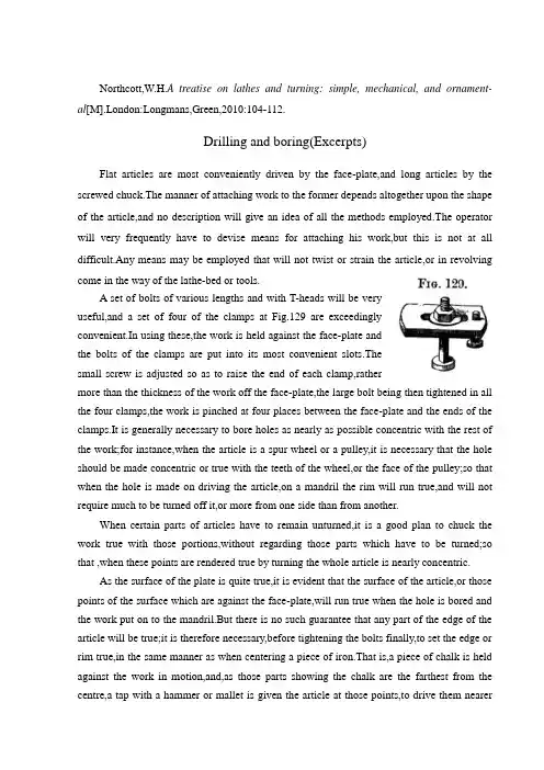
Northcott,W.H.A treatise on lathes and turning: simple, mechanical, and ornament-al[M].London:Longmans,Green,2010:104-112.Drilling and boring(Excerpts)Flat articles are most conveniently driven by the face-plate,and long articles by the screwed chuck.The manner of attaching work to the former depends altogether upon the shape of the article,and no description will give an idea of all the methods employed.The operator will very frequently have to devise means for attaching his work,but this is not at all difficult.Any means may be employed that will not twist or strain the article,or in revolvingcome in the way of the lathe-bed or tools.A set of bolts of various lengths and with T-heads will be veryuseful,and a set of four of the clamps at Fig.129 are exceedinglyconvenient.In using these,the work is held against the face-plate andthe bolts of the clamps are put into its most convenient slots.Thesmall screw is adjusted so as to raise the end of each clamp,rathermore than the thickness of the work off the face-plate,the large bolt being then tightened in all the four clamps,the work is pinched at four places between the face-plate and the ends of the clamps.It is generally necessary to bore holes as nearly as possible concentric with the rest of the work;for instance,when the article is a spur wheel or a pulley,it is necessary that the hole should be made concentric or true with the teeth of the wheel,or the face of the pulley;so that when the hole is made on driving the article,on a mandril the rim will run true,and will not require much to be turned off it,or more from one side than from another.When certain parts of articles have to remain unturned,it is a good plan to chuck the work true with those portions,without regarding those parts which have to be turned;so that ,when these points are rendered true by turning the whole article is nearly concentric.As the surface of the plate is quite true,it is evident that the surface of the article,or those points of the surface which are against the face-plate,will run true when the hole is bored and the work put on to the mandril.But there is no such guarantee that any part of the edge of the article will be true;it is therefore necessary,before tightening the bolts finally,to set the edge or rim true,in the same manner as when centering a piece of iron.That is,a piece of chalk is held against the work in motion,and,as those parts showing the chalk are the farthest from the centre,a tap with a hammer or mallet is given the article at those points,to drive them nearerthe centre of the lathe.This is repeated until the chalk touches either all round,or at opposite points,when the clamp bolts may be tightened and the boring commenced.When articles have to be true with their inside edges,it is evident that this operation must be reversed.Wherever the chalk shows,those points must be hammered away from the centre.It is a difficult matter for one pair of hands to hold work against the face-plate whilst putting in the bolts for fastening it on in place.Workmen are in the habit of keeping it temporarily in place by forcing it against the face-plate by the boring bit or drill and the centre of the moving headstock.This practice cannot altogether be recommended,as,besides a direct tendency to damage the points of the drill and of the centre,it is a very frequent occurrence for the whole—the work and drill to—come down with a run on to the lathe-bed or to the ground;and this leads to serious damage to all things concerned,as the workman will readily admit if his toes happen to be between the work and the ground.Other more careful workmen—if the work have a rough hole through it already—fasten the work temporarily to the face-plate by means of a bolt,screwing into the centre hole of the lathe-spindle,and a piece of straight iron with a hole through it,for a cross piece to span the hole.This practice is certainly all that can be desired,so far as both safety and convenience go;but it has one objection—the screwing and unscrewing of this bolt are apt to damage or wear the centre hole,and cause the centre to fit slackly.Probably the best plan,when chucking heavy work,is,either to put a block of woo-d of the right height under the work,or to remove the face-plate from the lathe,and lay it horizontal,with its face upwards,when the work may be fastened to it with ease and convenience.When the work is properly chucked,it is set in motion,and the place where the hole is to be commenced should be trued up.The boring-rest is then put in place,just in front of the work;care being taken not to put it near enough for the bolts in revolving to strike against it.There are two holes in this boring-rest;one—the large one—is for the boring bits,the small one is for the drills.One of these holes is placed just opposite the centre of the work,and the proper drill or bit is put through it;the other end of the bits is furnished with a centre mark,into which the centre of the moving headstock must be placed,and the cutting edge of the drill forced into the revolving work,by moving the hand-wheel and forcing out the screw.The rectangular hole in the boring-rest only prevents the bit from revolving;besides this,it has to be kept steady,especially at the commencement of the hole.If the hole be a small one,the boring-wrench is put on over the drill,and the other end of the lever forced down bythe workman's left hand.When the hole is a large one,the pressure thus obtained is not enough;but a larger lever of the same sort is then used,and a good heavy weight hung on to its end,and kept there whilst the bit is cutting its way through the hole.If the article be of wrought iron or steel,the cutting edge of the bit must be kept moist with soapsuds or soda-water;but with brass and cast-iron this is not required.In cutting large holes out of the solid,all the material cannot be removed by one instrument.A small drill must first be sent through,to be followed by a series of others,each taking an increasing cut,until the required size of the hole is nearly obtained,when the last bit should be carefully sent through;but it must not be made to take so heavy a cut as the bits preceding it.In taking a series of heavy cuts at the hole,the metal composing the—article especially if cast-iron or brass—will be rendered rather hot by the friction;it is,therefore,a good plan to allow the article to cool before passing through the finishing or last bit.If this be not done,and the hole is finished whilst the surrounding metal is hot,it will be found that when the metal has cooled,the finishing bit is unable to enter again owing to the contraction of the metal.It may,however,happen that the spindle to work into the hole has been made rather under the standard size.In this case it will be advisable to take advantage of this expansion and contraction of the metal,and make it subservient to our purpose,by boring the last cut but one with a dull bit,and taking a heavy cut.The metal will then be made very hot and the hole will expand;so that if the finishing bit be then quickly passed through the result will be that when the metal cools the hole will again contract,and form a closer fit with the spindle previously turned too small.These little facts are small in themselves;;but,by bearing them in mind,they may frequently be turned to useful account.It is scarcely necessary to observe that,in all cases,care must be taken not to exceed a certain heat,or to allow the work to get hot enough to lower the temper of the tool.Long cylindrical or other shaped articles,through which a holeis required,cannot be conveniently attached to the face-plate;andtherefore,for these articles,the screwed or bell-chuck, Fig.121,isused.The chuck being put on the lathe-spindle,the article isinserted between the screws,which are then screwed down to encompass and tightly hold it.The beginner will,probably,have some little difficulty in adjusting these screws so as to hold the work true;but the matter is much simplified by trueing the inside set of screws first,and afterwards adjusting the outside ones.These screws should be set down tight enough to prevent the article slipping or moving about;but if when the hole is made the material will be thin,care should be taken not to set the screws down tighter than necessary,as otherwise the metal will be compressed,and the hole rendered out of shape in their neighbourhood.When the articles to be drilled are too long for this chuck alone,the ends are turned up true for an inch or two;and one end is then chucked true,and held between the outside set only of the screws of the chuck,whilst the other end is supported by being run in the die-stay.This is fastened to the lathe-bed,at the proper place,and a wooden or metal bearing,having a hole the same size as the end of the work,is put into the V's,and adjusted so as to bring the centre of the work in the line of lathe-centres.The lathe isthen set in motion,and the hole drilled in the usual manner.For these long articles the best tool I know of is the D-bit,shown at Fig.124.Thistool is not half so much used as it ought to be,and,when used it is in conjunction with several other drills,and in such a roundabout manner that very few have patience touse it at all.These other drills are,however quite unnecessary after the D-bit is once started.The best manner of proceeding is as follows:First,place the boring-rest in position,and with an ordinary drill,of the same size as the D-bit,drill out a recess about1/8 or 1/4 of an inch in depth;remove the boring-rest,place the centre mark at the endof the D-bit,against the centre of the headstock,and screw up carefully until the drill isin-to cut;the hole may then be bored through with ease and the certainty of its being true.The drill must be kept well lubricated with soda-water and oil,and occasionally removed,and the hole cleared of shavings.If the hole be more than a foot long,it will be better to drill it half from each end;and,if great truth be required,two of these drills should be used as in the other cases,As in long holes it is rather difficult to keep drills well moistened,the workman will find it a good plan to have a small syringe,and inject or squirt the lubricant into the hole with force;by so doing,not only will the drill be kept wet,but the shavings will,in a great measure,be washed out and the hole cleared.On comparing the D form of drill with others,it will be found that the cutting edge is only equal to half the diameter of the hole;at the same time the drill stem is strong and well able to stand torsional strain,to which drills are mostly subject.In the ordinary drill,the cutting edge is equal to about one and a half diameters of the hole,whilst the stem is not nearly so well calculated to bear the strain.It therefore appears reasonable to conclude that the D-bit is better adapted than the others to cut a long hole out of the solid,or indeed to cut a long hole out at all;and this is found to be the case.I have had considerable practice with this drill,and have so much confidence in its powers that I would undertake,with it alone,to drill a one-inch hole through a shaft thirty orforty feet long.Holes required to be very smooth and straight,or require to be very slightly enlarged,are ground on a lead or copper lap,Fig.128.Also in the of articles which have been hardened or case hardened,the action of the fire is sure to have had a effect uponthe hole.In some cases the hole is bent;in others,the surface is rather blistered;in all cases it is rendered somewhat rough.All imperfections are removed by grinding the holeon a lap.The method of using these laps is very simple:they are put between the lathe-centres,and driven by a lathe-carrier in the ordinary way.The laps'surface is covered with a coat of fine emery powder and oil;the former may be caused to stick tothe lead by being slightly forced into it by a few taps with a hammer.The hole is then put on the lap,which is set in rapid rotation,and the article moved up and down;and,being prevented from moving around with the lap,the inside of the hole is ground by the adhering emery.The emery and oil must be continually replenished,and the surface of the lap kept moist with it,as,if allowed to get dry,the two surfaces will bind or cling to each other,and abrasion will result.If the article be heavy,precaution should be taken of turning it over,so as to grind every portion of the hole alike;otherwise the weight of the article,pressing all on one side of the hole,will cause it to be ground more on that side than the others,and the hole will be rendered non-circular.Care must also be taken to keep the middle of the lap well supplied with emery,and not to grind one end or the two ends of the hole larger than the middle.This,however,is a very common occurrence,and requires some little address to get over.Where practicable,it is also advisable to reverse the direction the lathe occasionally,as sometimes,in lapping out a hole,the hole will draw itself onwards,and the workman's whole force will be insufficient to prevent its tightening itself on and binding.In this case,the best way is to either let the work go around with the lap,and to immediately stop the lathe and drive the work back with a mallet before it gets cool and contracts firmly on to the lap;or to reverse the direction of the lathe,when the hole will generally run back of its own accord,unless it is gone on too far and become tight.It is sometimes a very difficult matter to get work off a lap when the grinding surfaces have allowed to get dry and to abrade themselves.威廉·亨利·诺斯考特.论车床和车削:简单,机械,装饰[M].伦敦:朗文公司,2010:104-112.钻和镗(摘录)平的制品最方便的驱动是通过面板,长的制品用螺纹卡盘。

中北大学信息商务学院本科毕业设计英文参考资料题目 Lathes系名专业姓名学号指导教师2016年6 月2 日译文标题车床简介原文标题Lathes作者(Serope kalpakjian)译名卡尔帕基安国籍美国原文出处/原文:LathesLathes are machine tools designed primarily to do turning, facing and boring, Very little turning is done on other types of machine tools, and none can do it with equal facility. Because lathes also can do drilling and reaming, their versatility permits several operations to be done with a single setup of the work piece. Consequently, more lathes of various types are used in manufacturing than any other machine tool.The essential components of a lathe are the bed, headstock assembly, tailstock assembly, and the leads crew and feed rod.The bed is the backbone of a lathe. It usually is made of well normalized or aged gray or nodular cast iron and provides s heavy, rigid frame on which all the other basic components are mounted. Two sets of parallel, longitudinal ways, inner and outer, are contained on the bed, usually on the upper side. Some makers use an inverted V-shape for all four ways, whereas others utilize one inverted V and one flat way in one or both sets, They are precision-machined to assure accuracy of alignment. On most modern lathes the way are surface-hardened to resist wear and abrasion, but precaution should be taken in operating a lathe to assure that the ways are not damaged. Any inaccuracy in them usually means that the accuracy of the entire lathe is destroyed.The headstock is mounted in a foxed position on the inner ways, usually at the left end of the bed. It provides a powered means of rotating the word at various speeds . Essentially, it consists of a hollow spindle, mounted in accurate bearings, and a set of transmission gears-similar to a truck transmission—through which the spindle can be rotated at a number of speeds. Most lathes provide from 8 to 18 speeds, usually in a geometric ratio, and on modern lathes all the speeds can be obtained merely by moving from two to four levers. An increasing trend is to provide a continuously variable speed range through electrical or mechanical drives.Because the accuracy of a lathe is greatly dependent on the spindle, it is of heavyconstruction and mounted in heavy bearings, usually preloaded tapered roller or ball types. The spindle has a hole extending through its length, through which long bar stock can be fed. The size of maximum size of bar stock that can be machined when the material must be fed through spindle.The tailsticd assembly consists, essentially, of three parts. A lower casting fits on the inner ways of the bed and can slide longitudinally thereon, with a means for clamping the entire assembly in any desired location, An upper casting fits on the lower one and can be moved transversely upon it, on some type of keyed ways, to permit aligning the assembly is the tailstock quill. This is a hollow steel cylinder, usually about 51 to 76mm(2to 3 inches) in diameter, that can be moved several inches longitudinally in and out of the upper casting by means of a hand wheel and screw.The size of a lathe is designated by two dimensions. The first is known as the swing. This is the maximum diameter of work that can be rotated on a lathe. It is approximately twice the distance between the line connecting the lathe centers and the nearest point on the ways, The second size dimension is the maximum distance between centers. The swing thus indicates the maximum work piece diameter that can be turned in the lathe, while the distance between centers indicates the maximum length of work piece that can be mounted between centers.Engine lathes are the type most frequently used in manufacturing. They areheavy-duty machine tools with all the components described previously and have power drive for all tool movements except on the compound rest. They commonly range in size from 305 to 610 mm(12 to 24 inches)swing and from 610 to 1219 mm(24 to 48 inches) center distances, but swings up to 1270 mm(50 inches) and center distances up to3658mm(12 feet) are not uncommon. Most have chip pans and a built-in coolant circulating system. Smaller engine lathes-with swings usually not over 330 mm (13 inches ) –also are available in bench type, designed for the bed to be mounted on a bench on a bench or cabinet.Although engine lathes are versatile and very useful, because of the time required for changing and setting tools and for making measurements on the work piece, thy are not suitable for quantity production. Often the actual chip-production tine is less than 30% of the total cycle time. In addition, a skilled machinist is required for all the operations, and such persons are costly and often in short supply. However, much of the operator’s time is consumed by simple, repetitious adjustments and in watching chips being made. Consequently, to reduce or eliminate the amount of skilled labor that is required, turret lathes, screw machines, and other types of semiautomatic and automatic lathes have been highly developed and are widely used in manufacturing.2 Numerical ControlOne of the most fundamental concepts in the area of advanced manufacturing technologies is numerical control (NC). Prior to the advent of NC, all machine tools ere manually operated and controlled. Among the many limitations associated with manual control machine tools, perhaps none is more prominent than the limitation of operator skills. With manual control, the quality of the product is directly related to and limited to the skills of the operator. Numerical control represents the first major step away from human control of machine tools.Numerical control means the control of machine tools and other manufacturing systems through the use of prerecorded, written symbolic instructions. Rather than operating a machine tool, an NC technician writes a program that issues operational instructions to the machine tool. For a machine tool to be numerically controlled, it must be interfaced with a device for accepting and decoding the programmed instructions, known as a reader.Numerical control was developed to overcome the limitation of human operators, and it has done so. Numerical control machines are more accurate than manually operated machines, they can produce parts more uniformly, they are faster, and the long-run tooling costs are lower. The development of NC led to the development of several other innovations in manufacturing technology:Electrical discharge machining,Laser cutting,Electron beam welding.Numerical control has also made machine tools more versatile than their manually operated predecessors. An NC machine tool can automatically produce a wide of parts, each involving an assortment of widely varied and complex machining processes. Numerical control has allowed manufacturers to undertake the production of products that would not have been feasible from an economic perspective using manually controlled machine tolls and processes.Like so many advanced technologies, NC was born in the laboratories of the Massachusetts Institute of Technology. The concept of NC was developed in the early 1950s with funding provided by the U.S. Air Force. In its earliest stages, NC machines were able to made straight cuts efficiently and effectively.However, curved paths were a problem because the machine tool had to be programmed to undertake a series of horizontal and vertical steps to produce a curve. The shorter the straight lines making up the steps, the smoother is the curve, Each line segment in the steps had to be calculated.This problem led to the development in 1959 of the Automatically Programmed Tools (APT) language. This is a special programming language for NC that uses statementssimilar to English language to define the part geometry, describe the cutting tool configuration, and specify the necessary motions. The development of the APT language was a major step forward in the fur ther development from those used today. The machines had hardwired logic circuits. The instructional programs were written on punched paper, which was later to be replaced by magnetic plastic tape. A tape reader was used to interpret the instructions written on the tape for the machine. Together, all of this represented a giant step forward in the control of machine tools. However, there were a number of problems with NC at this point in its development.A major problem was the fragility of the punched paper tape medium. It was common for the paper tape containing the programmed instructions to break or tear during a machining process. This problem was exacerbated by the fact that each successive time a part was produced on a machine tool, the paper tape carrying the programmed instructions had to be rerun through the reader. If it was necessary to produce 100 copies of a given part, it was also necessary to run the paper tape through the reader 100 separate tines. Fragile paper tapes simply could not withstand the rigors of a shop floor environment and this kind of repeated use.This led to the development of a special magnetic plastic tape. Whereas the paper carried the programmed instructions as a series of holes punched in the tape, the plastic tape carried the instructions as a series of magnetic dots. The plastic tape was much stronger than the paper tape, which solved the problem of frequent tearing and breakage. However, it still left two other problems.The most important of these was that it was difficult or impossible to change the instructions entered on the tape. To made even the most minor adjustments in a program of instructions, it was necessary to interrupt machining operations and make a new tape. It was also still necessary to run the tape through the reader as many times as there were parts to be produced. Fortunately, computer technology became a reality and soon solved the problems of NC associated with punched paper and plastic tape.The development of a concept known as direct numerical control (DNC) solved the paper and plastic tape problems associated with numerical control by simply eliminating tape as the medium for carrying the programmed instructions. In direct numerical control, machine tools are tied, via a data transmission link, to a host computer. Programs for operating the machine tools are stored in the host computer and fed to the machine tool an needed via the data transmission linkage. Direct numerical control represented a major step forward over punched tape and plastic tape. However, it is subject to the same limitations as all technologies that depend on a host computer. When the host computer goes down, the machine tools also experience downtime. This problem led to the development of computernumerical control.3 TurningThe engine lathe, one of the oldest metal removal machines, has a number of useful and highly desirable attributes. Today these lathes are used primarily in small shops where smaller quantities rather than large production runs are encountered.Th e engine lathe has been replaced in today’s production shops by a wide variety of automatic lathes such as automatic of single-point tooling for maximum metal removal, and the use of form tools for finish on a par with the fastest processing equipment on the scene today.Tolerances for the engine lathe depend primarily on the skill of the operator. The design engineer must be careful in using tolerances of an experimental part that has been produced on the engine lathe by a skilled operator. In redesigning an experimental part for production, economical tolerances should be used.Turret Lathes Production machining equipment must be evaluated now, more than ever before, this criterion for establishing the production qualification of a specific method, the turret lathe merits a high rating.In designing for low quantities such as 100 or 200 parts, it is most economical to use the turret lathe. In achieving the optimum tolerances possible on the turrets lathe, the designer should strive for a minimum of operations.Automatic Screw Machines Generally, automatic screw machines fall into several categories; single-spindle automatics, multiple-spindle automatics and automatic chucking machines. Originally designed for rapid, automatic production of screws and similar threaded parts, the automatic screw machine has long since exceeded the confines of this narrow field, and today plays a vital role in the mass production of a variety of precision parts. Quantities play an important part in the economy of the parts machined on the automatic screw machine. Quantities less than on the automatic screw machine. The cost of the parts machined can be reduced if the minimum economical lot size is calculated and the proper machine is selected for these quantities.Automatic Tracer Lathes Since surface roughness depends greatly on material turned, tooling , and feeds and speeds employed, minimum tolerances that can be held on automatic tracer lathes are not necessarily the most economical tolerances.In some cases, tolerances of 0.05mm are held in continuous production using but one cut . groove width can be held to 0.125mm on some parts. Bores and single-point finishes can be held to 0.0125mm. On high-production runs where maximum output is desirable, a minimum tolerance of 0.125mm is economical on both diameter and length of turn。
英语原文:Design Of Tool Machine PropResearch significanceThe original knife machine control procedures are designed individually, not used tool management system, features a single comparison, the knife only has to find the tool knife, knife positioning the shortest path, axis tool change, but does not support large-scale tool.Automatic knife in the knife election, in the computer memory knife-election on the basis of using the Siemens 840 D features, and the election procedures knife more concise, and complete the space Daotao View. ATC use the knife rapid completion of STEP-7 programming, and have been tested in practice. In the positioning of the knife, PLC controlled modular design method, which future production of similar machines will be very beneficial, it is easy to use its other machine. Automatic tool change systems will be faster growth, reduced tool change time, increase the positioning accuracy tool is an important means to help NC technology development.Tool and inventory components of modern production is an important link in the management, especially for large workshop management. The traditional way of account management, and low efficiency, high error rate, and not sharing information and data, tools and the use of state can not track the life cycle, are unable to meet the current information management needs. With actual production, we have to establish a workshop tool for the three-dimensional tool storage system to meet the knife workshop with auxiliary storage and management needs.The system uses optimization technology, a large number of computer storage inventory information, timely, accurate, and comprehensive tool to reflect the inventory situation. The entire system uses a graphical interface, man-machine dialogue tips from the Chinese menu, select various functions can be realized and the importation of all kinds of information. Management system using online help function. Through the workshop management, network management and sharing of information. Have automated inventory management, warehousing management tool, a tool for the management and statistical functions.1.System components and control structureThe entire system, including the structure and electrical machinery control systems.1.1.1Mechanical structure and working principleTool from the stent, drive, drive system, Turret, shielding, control system, and electrical components. Support from the column, beam, the upper and lower guide Central track, and track support component.1) Drive for the system chosen VVVF method. Cone used brake motors, with VVVF by Cycloid reducer through sprocket drive.2) Drag a variable frequency drive system and control technology. VVVF adopted, will speed drive shaft in the normal range adjustment to control the speed rotary turret to 5 ~ 30mm in, the drive shaft into two, two under through sprocket, the two profiled rollers Chain driven rotating shelves. Expansion chain adopted by the thread tight regulation swelling, swelling the regular way. - Conditioned, under the same chain-of-conditioning, so that the chain of uniform.3) Turret and shields the entire total of 14 independent Turret. 13 of them as a socket-Turret, as adrawer-Turret, each Turret back through the pin and, under the conveyor chain link chain plate, installed at the bottom roller, chain driven rotating turret rotation along the track. Outlet-Turret and BT50-BT40 Turret Turret two kinds of forms. To strengthen management, security, landscaping modeling, shelf peripherals and shields. Turret-drawer drawer placed at six other Des V oeux a knife, can be categorized with some of knife auxiliary equipment, such as bits, such as turning tools.1.1.2.Electrical Control SystemThis tool storage systems is the main electrical control their shelves for operational control and position control. Operational control equipment, including operation of the start of braking control. Position Control is the main location and address of the shelves for testing. Control system as shown in Figure 1.图 1 Tool Control System for the1) Electric Transmission horizontal rotary tool storage systems are the mechanical movements are repeated short-term work system. And the run-time system needs some speed, speed transmission needs, the system will use VVVF method can be used simple structure, reliable operation of the motor and frequency inverter.2) Control of the system is divided into two kinds of manual control and automatic control, manual control as a general reserve and debugging methods of work; ways to the system control computer (IPC) and the control unit (inverter contactor , etc.) consisting of a control system.3) location and positioning accuracy of the system automatically identify the site and location using a detection device as proximity switches, relays through the plate-point isolation and the number plate recorded close to the switching signal acquisition and operation of Hutchison with a Optimal Path addressable identify the current location and shelves of the purpose of the shelf location. In order to enable a more accurate positioning system, adopted two photoelectric switches, to detect the two shelves of the two films.1.2.The functions of the knifeknife The is the role of reserves a certain number of tools, machine tool spindle in hand to achieve the fungibility a disc cutter knife is the type of library, the chain knives, and other means, in the form of the knife and capacity according to the Machine Tool to determine the scope of the process.mon typesThe knife is a tool storage devices, the common knife mainly in the following forms:(1) the turret knifeIncluding the first level turret vertical turret and the first two, see Figure 2.6 a) and b):(2) the disc cutterDisc knife in the library with discoid knife, cutting tool along See how vertical arrangement (including radial and axial from knife from knife), along See how radial array into acute or arranged in the form of the knife. Simple, compact, more applications, but are ring-cutter, low utilization of space. Figure 2.7 a) to c). If the knife storage capacity must be increased to increase the diameter of the knife, then the moment of inertia also increased correspondingly, the election campaign long knife. Tool number not more than 32 general. Cutter was multi-loop order of the space utilization knife, but inevitably given the knife from complex institutions, applicable to the restricted space Machine Tool storage capacity and more occasions. Two-disc structure is two smaller capacity knife on both sides of the sub-spindle place, more compact layout, the number of certificates corresponding increase knife, apply to small and medium-sized processing center.(3) the chain knifeIncluding single-and multi-ring chain ring chain, chain link can take ma ny forms change, see Figure 2.8 a) to c), the basic structureFeatures: knife apply to thelarger capacity of theoccasion, the space of thesmall number of generallyapplicable to the tool in the30-120. Only increase thelength of the chain tool willincrease the number shouldnot be increasedcircumferential speed of itsmoment of inertia of theknife does not increase thedisc as large.(4) linear combination knife and the knife libraryThe linear knife simple structure in Figure 2.9, tool single order, the capacity of small knife, used for CNC lathe and drill press on. Because the location of fixed knife, ATC completed action by the spindle without manipulator. The cutter knife is generally the turret combination turret with a combination of the disc cutter knife and the chain combination. Every single knife the knife certificates of smaller, faster tool change. There are also some intensive drum wheel, and the lattice-type magazine for the knife, the knife-intensive though. Small footprint, but because of structural constraints, basically not used for single processing center, the concentration used for FMS for the knife system.1.4 Tool storage capacityTool storage capacity of the first to consider the needs of processing, from the use of point of view, generally 10 to 40 knives, knife will be the utilization of the high, and the structure is compact.1.5 Tool options(1) choose to order processing tool according to the order, followed Add to the knife every knife in the Block. Each tool change, the order of rotation of a cutter knife on location, and remove the need knives, has been used by the cutter knife can be returned to the original Block, can also order Add Block, a knife. However, as the knife in the tool in different processes can not be repeated use of the knife must increase the capacity and lower utilization rate.(2) most of the arbitrary choice of the current system of using arbitrary NC election knives, divided into Daotao coding, coding and memory-cutter, three. Daotao coding tool code or knives or Daotao need to install the code used to identify, in accordance with the general principle of binary coding coding. Tool knife election coding method uses a special knife handle structure, and each of the coding tool. Each of the tool has its own code, thereby cutting tool can be in different processes repeatedly used, not to replace the tool back at the original knife, the knife capacity can be reduced accordingly. Memory-election this paper knife, in this way can knives and knife in the position corresponding to the Daotao memory of the PLC in the NC system, no matter which tool on the Inner knife, tool information is always there in mind, PLC . On the knife with position detection devices, will be the location of each Daotao. This tool can be removed and sent back to arbitrary. On the knife is also a mechanical origin, every election, the nearest knife selection.1.6.Control of the knife(1) the knife as a system to control the positioning axis. In the ladder diagram in accordance with the instructions for computing T code comparison of the output angle and speed of instructions to the knife the knife servo drive servo motor. Tool storage capacity, rotation speed, and / deceleration time, and other system parameters can be set in such a manner free from any outside influence positioning accurate and reliable but the cost is higher.(2) knife from the hydraulic motor drives, fast / slow the points, with proximity switches count and positioning. In comparison ladder diagram of the current storage system knife (knife spindle) and goals knife (pre-knife) and computing, then output rotation instructions, judging by the shortest path rotation in place. This approach requires sufficient hydraulic power and electromagnetic valve knife the rotational speed can be adjusted through the throttle. But over time may be oily hydraulic, oil temperature and environmental factors impact the change in velocity and accuracy. Not generally used in large and medium-sized machine tool change frequently.(3) the knife from AC asynchronous motor driven cam mechanism (Markov institutions), with proximity switches count, which means stable operation, and generally accurate and reliable positioning cam used in conjunction with a mechanical hand, ATC fast-positioning.2. ATC, the main types, characteristics, and the scope of application2.1 Auto Rotary ToolRotary Tool automatically on the useof CNC machine tool is a simpleinstallation of automatic tool change, theQuartet and 47.60 Turret Tool variousforms, such as rotary turret were installedon four, six or more of the Tool , NCinstructions by ATC. Rotary Tool has twovertical and horizontal, relatively simplestructure, applicable to economic CNClathe.Rotary Tool in the structure must havegood strength and stiffness, resistance tobear rough Cutting Tool in the cuttingforce and reduce the role of deformationand improve processing accuracy.Rotating Tool to choose reliablepositioning programme structure andreasonable position, in order to ensure thateach rotary turret to a higher position afterrepeated positioning accuracy (typically0.001 to 0.005mm). Figure 2.1 shows thespiral movements of the Quartet Turret.Auto Rotary Tool in the simplest ofATC, is 180 º rotary ATC devices, asshown in Figure 2.2 ATC instructionsreceived, the machine control system put ATC spindle control to the designated location at the same time, the tool movement to the appropriate location, ATC, with the rotary axis and at the same time, the knives matching tool; drawbars from Spindle Cutting Tools rip, ATC, will be the tool from their position removed; ATC, 180 º rotary tool spindle and the tool and tool away; ATC, the Rotary At the same time, the tool refocusing its position to accept Spindle removed from the cutting tool; Next, ATC, will be replaced with the cutter knives were unloaded into the spindle and tool: Finally, back to the original ATC, "standby" position. At this point, ATC completed procedures to continue to run. This ATC, the main advantage of simple structure, the less movement, fast tool change. The main disadvantage is that knives must be kept in parallel with the axis of the plane, and after the home side compared to the tool, chip and liquid-cutting knife into the folder, it is necessary to the tool plus protection. Cone knife folder on the chip will cause ATC error, or even damage knife folders, and the possibility of spindle. Some processing centre at the transfer, and the tool side. When the ATC command is called, the transfer-cutter knives will be removed, the machine go forward, and positioning with the ATC, in line with the position. 180 º "Rotary ATC devices can be used horizontal machine, can also be used for vertical machining centers.2. 2 ATC head-turret installedWith rotating CNC machine tool often used such ATC devices, with a few turret head spindle, each with a spindle on both knives, the first tower interim process can be automatic tool change-realization. The advantage is simple structure, tool change time is short, only about 2 s. However, due to spatial constraints, the number of spindle can not be too much, usually only apply to processes less, not to high precision machine tools, such as the NC drill, such as CNC milling machine. In recent years there has been a mechanical hand and the turret head with a knife for the automatic tool change ATC devices, as shown in Figure 2.3. It is in fact a turret head ATC, and the knife-ATC device combination. The principle is as follows:5 turret on the first two tool spindle 3 and 4, when using the tool spindle 4 processing tool, the manipulator 2 will be the next step to the need for the tool does not work on the tool spindle 3 until after the completion of this process , the first rotary turret 180 º, ATC completed. ATC most of their time and processing time coincidence, the only real tool change time turret transposition of the first time, this approach mainly used for ATC and NC NC drilling file bed.2. 3.Daidao system for the automatic tool changeFigure 2.4 shows the knife and the whole machine tool CNC machine tools for the appearance of Fig. Figure 2.5 shows the knife and split-type machine to the appearance of CNC machine tool plans.At this point, knife storage capacity, a heavier tool can, and often additional transport unit to complete the knife between the spindle and cutting tool transport.Daidao the knife from the ATC, the election knives, automatic loading and unloading machine tool and tool exchange institutions (manipulator), composed of four parts, used widely.Tool Automatic Tool Change the manipulator system, the whole process more complicated ATC. We must first used in the processing of all installed in the standard tool on the knife handle in the machine outside the pre-size, according to a certain way Add to the knife. ATC, selected first in the knife knife, and then from ATC, from the knife from the knife or spindle, exchange, the new knife into the spindle, the old knife back into the knife.ATC, as the former two knives to accommodate a limited number can not be too many, can not meet the needs of complex parts machining, CNC machine tool Automatic Tool Change Daidao the use of the automatic tool change devices. The knife has more capacity, both installed in the spindle box side or above. As for the automatic tool change Daidao device CNC machine tool spindle box only a spindle, spindle components to high stiffness to meet the machining requirements. The number of establishments in larger knife, which can meet the more complex parts of the machining processes, significantly improving productivity. Daidao system for the automatic tool change applied to drilling centres and CNC machining centers. The comparison drawn Daidao automatic tool change system is the most promising.3.PLC control of the knife random mode of election 3. 1Common methods of automatic election knifeAutomatic control of the knife CNC refers to the system after the implementation of user instructions on the knife library automation process, including the process to find knives and automatic tool change [(63,71]. CNC Machining Center device (CNC) directive issued by the election knife , a knife, the tool required to take the knife position, said the election automatic knife. automatically elected knife There are two ways: random sequence election knives and knife election method.3.1.1 order election knifeTool Selection order is the process tool according to the sequence of the insert knife, the use of knives in order to take place, used knives back at the original knife, can also order Add Block, a knife. In this way, no need Tool identification devices, and drive control is a relatively simple, reliable and can be used directly from the points of the knife machinery to achieve. But the knives in each of the tool in different processes can not be reused, if the tool is installed in accordance with the order of the knife, there will be serious consequences. The need to increase the number of knives and knife the capacity of the tool and reduce the utilization of the knife.3.1.2Random election knifeRandom election under the knife is arbitrary instructions to select the required tools, then there must be tool identification devices. Tool knife in the library do not have the processing in accordance with the order of the workpiece can be arbitrary storage. Each of the tool (or knife blocks) are for a code, automatic tool change, the rotary cutter, every tool have been the "tool identification device" acceptable identification. When CNC tool code and the code in line with directives of the tool selected, the rotary cutter knives will be sent to the ATC position, waiting to grab manipulator. Random knife election is the advantage of the cutter knife in the order has nothing to do with the processing sequence, the same tool can be used repeatedly. Therefore, the relatively small number of knives, knife the corresponding smaller. Random elections knife on the tool must be coded to identify. There are three main coding.1. Tool coding. Adopt special knife handle structure coding, the drawbars on the knife handle back-end packages such as spacing of the coding part of the lock-nut fixed. Coding diameter ring diameter of a size two, respectively, said that binary "1" and "0" to the two rings are different, can be a series of code. For example, there are six small diameter of the ring can be made to distinguish between 63 (26-1 = 63) of the coding tool. All of 0 normally not allowed to use the code, to avoid the cutter knife Block did not confuse the situation.2. Knife Block coding. On the knife Block coding, coding tool, and tool into line with the number of knives in the Block. ATC knife when the rotation, so that each knife seats followed through knowledge knife, knife found blocks, knives stopped the rotation. At this time there is no knife handle encoding part of the knife handle simplified.3. Annex coding methods. This style of coding keys, coded cards, coding and coding-disc, which is the most widely used coding keys. First toknives are attached to a tool of the show wrapped coding keys, and when the cutter knife to the store at knife in, so put the number of keys to remember knife Block Road, will be inserted into key to the coding Block next to the key hole in the seat for the knife to the numbers. ConclusionFocused on in today's manufacturing environment tool storage and management of new models and methods, practical application of good results in systems integration and optimization, and other aspects of operations will be further explored, so that it has a higher theoretical and practical level.译文:机床刀具设计课题研究意义机床原来的刀库控制程序是单独设计的,没有采用刀具管理系统,功能也比较单一,只实现了刀库刀具的找刀、刀库最短路径定位、主轴换刀,而且不支持大型刀具。

机床行业中英文对照(一)机床行业中英文对照(一)3-Jaws indexing spacers 三爪、分割工具头A.T.C.system 加工中心机刀库Aluminum continuous melting & holding furnaces 连续溶解保温炉Balancing equipment 平衡设备Bayonet 卡口Bearing fittings 轴承配件Bearing processing equipment 轴承加工机Bearings 轴承Belt drive 带传动Bending machines 弯曲机Blades 刀片Blades,saw 锯片Bolts,screws & nuts 螺栓,螺帽及螺丝Boring heads 搪孔头Boring machines 镗床Cable making tools 造线机Casting,aluminium 铸铝Casting,copper 铸铜Casting,gray iron 铸灰口铁Casting,malleable iron 可锻铸铁Casting,other 其他铸造Casting,steel 铸钢Chain drive 链传动Chain making tools 造链机Chamfer machines 倒角机Chucks 夹盘Clamping/holding systems 夹具/支持系统CNC bending presses 电脑数控弯折机CNC boring machines 电脑数控镗床CNC drilling machines 电脑数控钻床CNC EDM wire-cutting machines 电脑数控电火花线切削机CNC electric discharge machines 电脑数控电火花机CNC engraving machines 电脑数控雕刻机CNC grinding machines 电脑数控磨床CNC lathes 电脑数控车床CNC machine tool fittings 电脑数控机床配件CNC milling machines 电脑数控铣床CNC shearing machines 电脑数控剪切机CNC toolings CNC刀杆CNC wire-cutting machines 电脑数控线切削机Conveying chains 输送链Coolers 冷却机Coupling 联轴器Crimping tools 卷边工具Cutters 刀具Cutting-off machines 切断机Diamond cutters 钻石刀具Dicing saws 晶圆切割机Die casting dies 压铸冲模Die casting machines 压铸机Dies-progressive 连续冲模Disposable toolholder bits 舍弃式刀头Drawing machines 拔丝机Drilling machines 钻床Drilling machines bench 钻床工作台Drilling machines,high-speed 高速钻床Drilling machines,multi-spindle 多轴钻床Drilling machines,radial 摇臂钻床Drilling machines,vertical 立式钻床drills 钻头Electric discharge machines(EDM) 电火花机Electric power tools 电动刀具Engraving machines 雕刻机Engraving machines,laser 激光雕刻机Etching machines 蚀刻机Finishing machines 修整机Fixture 夹具Forging dies 锻模Forging,aluminium 锻铝Forging,cold 冷锻Forging,copper 铜锻Forging,other 其他锻造Forging,steel 钢锻Foundry equipment 铸造设备Gear cutting machines 齿轮切削机Gears 齿轮Gravity casting machines 重力铸造机Grinder bench 磨床工作台Grinders,thread 螺纹磨床Grinders,tools & cutters 工具磨床Grinders,ultrasonic 超声波打磨机Grinding machines 磨床Grinding machines,centerless 无心磨床Grinding machines,cylindrical 外圆磨床Grinding machines,universal 万能磨床Grinding tools 磨削工具Grinding wheels 磨轮Hand tools 手工具Hard/soft and free expansion sheet making plant 硬(软)板(片)材及自由发泡板机组Heat preserving furnaces 保温炉Heating treatment funaces 熔热处理炉Honing machines 搪磨机Hydraulic components 液压元件Hydraulic power tools 液压工具机床行业中英文对照(一)Hydraulic power units 液压动力元件Hydraulic rotary cylinders 液压回转缸Jigs 钻模Lapping machines 精研机Lapping machines,centerless 无心精研机Laser cutting 激光切割Laser cutting for SMT stensil 激光钢板切割机Lathe bench 车床工作台Lathes,automatic 自动车床Lathes,heavy-duty 重型车床Lathes,high-speed 高速车床Lathes,turret 六角车床Lathes,vertical 立式车床Lubricants 润滑液Lubrication Systems 润滑系统Lubricators 注油机Machining centers,general 通用加工中心Machining centers,horizontal 卧式加工中心Machining centers,horizontal & vertical 卧式及立式加工中心Machining centers,vertical 立式加工中心Machining centers,vertical double-column type 立式双柱加工中心Magnetic tools 磁性工具Manifolds 集合管Milling heads 铣头Milling machines 铣床Milling machines,bed type 床身式铣床Milling machines,duplicating 仿形铣床Milling machines,horizontal 卧式铣床Milling machines,turret vertical 六角立式铣床Milling machines,universal 万能铣床Milling machines,vertical 立式铣床Milling machines,vertical & horizontal 立式及卧式铣床Mold & die components 模具单元Mold changing systems 换模系统Mold core 模芯Mold heaters/chillers 模具加热器/冷却器Mold polishing/texturing 模具打磨/磨纹Mold repair 模具维修Molds 模具Nail making machines 造钉机Oil coolers 油冷却器Overflow cutting machines for aluminium wheels 铝轮冒口切断机P type PVC waterproof rolled sheet making plant P型PVC高分子防水PCB fine piecing systems 印刷电器板油压冲孔脱料系统Pipe & tube making machines 管筒制造机Planing machines 刨床Planing machines vertical 立式刨床Pneumatic hydraulic clamps 气油压虎钳Pneumatic power tools 气动工具Powder metallurgic forming machines 粉末冶金成型机Presses,cold forging 冷锻冲压机presses,crank 曲柄压力机Presses,eccentric 离心压力机Presses,forging 锻压机Presses,hydraulic 液压冲床Presses,knuckle joint 肘杆式压力机Presses,pneumatic 气动冲床Presses,servo 伺服冲床Presses,transfer 自动压力机Pressing dies 压模Punch formers 冲子研磨器Quick die change systems 速换模系统Quick mold change systems 快速换模系统Reverberatory furnaces 反射炉Rollers 滚筒Rolling machines 辗压机Rotary tables 转台Sawing machines 锯床Sawing machines,band 带锯床Saws,band 带锯Saws,hack 弓锯Saws,horizontal band 卧式带锯Saws,vertical band 立式带锯shafts 轴Shapers 牛头刨床Shearing machines 剪切机Sheet metal forming machines 金属板成型机Sheet metal working machines 金属板加工机Slotting machines 插床spindles 主轴Stamping parts 冲压机Straightening machines 矫直机Switches & buttons 开关及按钮Tapping machines 攻螺丝机Transmitted chains 传动链Tube bending machines 弯管机Vertical hydraulic broaching machine 立式油压拉床Vises 虎钳Vises,tool-maker 精密平口钳Wheel dressers 砂轮修整器机床行业中英文对照(一)Woven-Cutting machines 织麦激光切割机Wrenches 扳手。

外语文献翻译摘自: 《制造工程与技术(机加工)》(英文版)《Manufacturing Engineering and Technology —Machining 》机械工业出版社 2004年3月第1版 页—564560P美 s. 卡尔帕基安(Serope kalpakjian)s.r 施密德(Steven R.Schmid) 著原文:20.9 MACHINABILITYThe machinability of a material usually defined in terms of four factors:1、Surface finish and integrity of the machined part; 2、Tool life obtained; 3、Force and power requirements; 4、 Chip control.Thus, good machinability good surface finish and integrity, long tool life, and low force And power requirements. As for chip control, long and thin (stringy) cured chips, if not broken up, can severely interfere with the cutting operation by becoming entangled in the cutting zone.Because of the complex nature of cutting operations, it is difficult to establish relationships that quantitatively define the machinability of a material. Inmanufacturing plants, tool life and surface roughness are generally considered to be the most important factors in machinability. Although not used much any more, approximate machinability ratings are available in the example below.20.9.1 Machinability Of SteelsBecause steels are among the most important engineering materials (as noted in Chapter 5), their machinability has been studied extensively. The machinability of steels has been mainly improved by adding lead and sulfur to obtain so-called free-machining steels.Resulfurized and Rephosphorized steels. Sulfur in steels forms manganese sulfide inclusions (second-phase particles), which act as stress raisers in the primaryshear zone. As a result, the chips produced break up easily and are small; this improves machinability. The size, shape, distribution, and concentration of these inclusions significantly influence machinability. Elements such as tellurium and selenium, which are both chemically similar to sulfur, act as inclusion modifiers in resulfurized steels.Phosphorus in steels has two major effects. It strengthens the ferrite, causing increased hardness. Harder steels result in better chip formation and surface finish. Note that soft steels can be difficult to machine, with built-up edge formation and poor surface finish. The second effect is that increased hardness causes the formation of short chips instead of continuous stringy ones, thereby improving machinability.Leaded Steels. A high percentage of lead in steels solidifies at the tip of manganese sulfide inclusions. In non-resulfurized grades of steel, lead takes the form of dispersed fine particles. Lead is insoluble in iron, copper, and aluminum and their alloys. Because of its low shear strength, therefore, lead acts as a solid lubricant (Section 32.11) and is smeared over the tool-chip interface during cutting. This behavior has been verified by the presence of high concentrations of lead on thetool-side face of chips when machining leaded steels.When the temperature is sufficiently high-for instance, at high cutting speeds and feeds (Section 20.6)—the lead melts directly in front of the tool, acting as a liquid lubricant. In addition to this effect, lead lowers the shear stress in the primary shear zone, reducing cutting forces and power consumption. Lead can be used in every grade of steel, such as 10xx, 11xx, 12xx, 41xx, etc. Leaded steels are identified by the letter L between the second and third numerals (for example, 10L45). (Note that in stainless steels, similar use of the letter L means “low carbon,” a condition that improves their corrosion resistance.)However, because lead is a well-known toxin and a pollutant, there are serious environmental concerns about its use in steels (estimated at 4500 tons of lead consumption every year in the production of steels). Consequently, there is a continuing trend toward eliminating the use of lead in steels (lead-free steels). Bismuth and tin are now being investigated as possible substitutes for lead in steels.Calcium-Deoxidized Steels. An important development is calcium-deoxidized steels, in which oxide flakes of calcium silicates (CaSo) are formed. These flakes, in turn, reduce the strength of the secondary shear zone, decreasing tool-chip interfaceand wear. Temperature is correspondingly reduced. Consequently, these steels produce less crater wear, especially at high cutting speeds.Stainless Steels. Austenitic (300 series) steels are generally difficult to machine. Chatter can be s problem, necessitating machine tools with high stiffness. However, ferritic stainless steels (also 300 series) have good machinability. Martensitic (400 series) steels are abrasive, tend to form a built-up edge, and require tool materials with high hot hardness and crater-wear resistance. Precipitation-hardening stainless steels are strong and abrasive, requiring hard and abrasion-resistant tool materials.The Effects of Other Elements in Steels on Machinability. The presence of aluminum and silicon in steels is always harmful because these elements combine with oxygen to form aluminum oxide and silicates, which are hard and abrasive. These compounds increase tool wear and reduce machinability. It is essential to produce and use clean steels.Carbon and manganese have various effects on the machinability of steels, depending on their composition. Plain low-carbon steels (less than 0.15% C) can produce poor surface finish by forming a built-up edge. Cast steels are more abrasive, although their machinability is similar to that of wrought steels. Tool and die steels are very difficult to machine and usually require annealing prior to machining. Machinability of most steels is improved by cold working, which hardens the material and reduces the tendency for built-up edge formation.Other alloying elements, such as nickel, chromium, molybdenum, and vanadium, which improve the properties of steels, generally reduce machinability. The effect of boron is negligible. Gaseous elements such as hydrogen and nitrogen can have particularly detrimental effects on the properties of steel. Oxygen has been shown to have a strong effect on the aspect ratio of the manganese sulfide inclusions; the higher the oxygen content, the lower the aspect ratio and the higher the machinability.In selecting various elements to improve machinability, we should consider the possible detrimental effects of these elements on the properties and strength of the machined part in service. At elevated temperatures, for example, lead causes embrittlement of steels (liquid-metal embrittlement, hot shortness; see Section 1.4.3), although at room temperature it has no effect on mechanical properties.Sulfur can severely reduce the hot workability of steels, because of the formation of iron sulfide, unless sufficient manganese is present to prevent such formation. Atroom temperature, the mechanical properties of resulfurized steels depend on the orientation of the deformed manganese sulfide inclusions (anisotropy). Rephosphorized steels are significantly less ductile, and are produced solely to improve machinability.20.9.2 Machinability of Various Other MetalsAluminum is generally very easy to machine, although the softer grades tend to form a built-up edge, resulting in poor surface finish. High cutting speeds, high rake angles, and high relief angles are recommended. Wrought aluminum alloys with high silicon content and cast aluminum alloys may be abrasive; they require harder tool materials. Dimensional tolerance control may be a problem in machining aluminum, since it has a high thermal coefficient of expansion and a relatively low elastic modulus.Beryllium is similar to cast irons. Because it is more abrasive and toxic, though, it requires machining in a controlled environment.Cast gray irons are generally machinable but are. Free carbides in castings reduce their machinability and cause tool chipping or fracture, necessitating tools with high toughness. Nodular and malleable irons are machinable with hard tool materials.Cobalt-based alloys are abrasive and highly work-hardening. They require sharp, abrasion-resistant tool materials and low feeds and speeds.Wrought copper can be difficult to machine because of built-up edge formation, although cast copper alloys are easy to machine. Brasses are easy to machine, especially with the addition pf lead (leaded free-machining brass). Bronzes are more difficult to machine than brass.Magnesium is very easy to machine, with good surface finish and prolonged tool life. However care should be exercised because of its high rate of oxidation and the danger of fire (the element is pyrophoric).Molybdenum is ductile and work-hardening, so it can produce poor surface finish. Sharp tools are necessary.Nickel-based alloys are work-hardening, abrasive, and strong at high temperatures. Their machinability is similar to that of stainless steels.Tantalum is very work-hardening, ductile, and soft. It produces a poor surfacefinish; tool wear is high.Titanium and its alloys have poor thermal conductivity (indeed, the lowest of all metals), causing significant temperature rise and built-up edge; they can be difficult to machine.Tungsten is brittle, strong, and very abrasive, so its machinability is low,although it greatly improves at elevated temperatures.Zirconium has good machinability. It requires a coolant-type cutting fluid,however, because of the explosion and fire.20.9.3 Machinability of Various MaterialsGraphite is abrasive; it requires hard, abrasion-resistant, sharp tools.Thermoplastics generally have low thermal conductivity, low elastic modulus, and low softening temperature. Consequently, machining them requires tools with positive rake angles (to reduce cutting forces), large relief angles, small depths of cut and feed, relatively high speeds, andproper support of the workpiece. Tools should be sharp.External cooling of the cutting zone may be necessary to keep the chips from becoming “gummy” and sticking to the tools. Cooling can usually be achieved with a jet of air, vapor mist, or water-soluble oils. Residual stresses may develop during machining. To relieve these stresses, machined parts can be annealed for a period of time at temperatures ranging from C ︒80 to C ︒160 (F ︒175to F ︒315), and then cooled slowly and uniformly to room temperature.Thermosetting plastics are brittle and sensitive to thermal gradients duringcutting. Their machinability is generally similar to that of thermoplastics.Because of the fibers present, reinforced plastics are very abrasive and aredifficult to machine. Fiber tearing, pulling, and edge delamination are significant problems; they can lead to severe reduction in the load-carrying capacity of the component. Furthermore, machining of these materials requires careful removal of machining debris to avoid contact with and inhaling of the fibers.The machinability of ceramics has improved steadily with the development of nanoceramics (Section 8.2.5) and with the selection of appropriate processing parameters, such as ductile-regime cutting (Section 22.4.2).Metal-matrix and ceramic-matrix composites can be difficult to machine, depending on the properties of the individual components, i.e., reinforcing or whiskers, as well as the matrix material.20.9.4 Thermally Assisted MachiningMetals and alloys that are difficult to machine at room temperature can be machined more easily at elevated temperatures. In thermally assisted machining (hot machining), the source of heat—a torch, induction coil, high-energy beam (such as laser or electron beam), or plasma arc—is forces, (b) increased tool life, (c) use of inexpensive cutting-tool materials, (d) higher material-removal rates, and (e) reduced tendency for vibration and chatter.It may be difficult to heat and maintain a uniform temperature distribution within the workpiece. Also, the original microstructure of the workpiece may be adversely affected by elevated temperatures. Most applications of hot machining are in the turning of high-strength metals and alloys, although experiments are in progress to machine ceramics such as silicon nitride.SUMMARYMachinability is usually defined in terms of surface finish, tool life, force and power requirements, and chip control. Machinability of materials depends not only on their intrinsic properties and microstructure, but also on proper selection and control of process variables.译文:20.9 可机加工性一种材料的可机加工性通常以四种因素的方式定义:1、分的表面光洁性和表面完整性。
中英文对照外文翻译(文档含英文原文和中文翻译)外文:Combination Boring MachineThe multi-purpose aggregate machine-tools has many names to describe it in the industrial field.It likes“the multitasking installment”, “the multi-purpose engine beds”, “the multi-procedure pr oduction system” and so on.It may be called the processing domain truly the nova and reduce the cost, the simplified disposition and has maintained in the US territory produces. In the past only they used the duty which many machine operations could complete, now it may concentrate to an engine bed on processes completes.As a result of market demand's unceasing change, the product life cycle is reducing unceasingly, today's market more intense demand multitasking installment concept. Carries out the fine profit management when the entire production environment, compared to having not concentrated the components processing to a machine on completes a finer profit.Some tradition's manufacturing industry manufacturer thought that the multi-purposeaggregate machine-tools are too complex, very difficult to find the appropriate operators also the difficult problem innovates on the spot on the insufficiency for the metal working basic principle and in the Production workshop related new engine bed use solution aspect training.Intuition type technical controlThe equipment use “carries off the quantity of heat” the type design, has different material which the lathe bed, the steeliness straight line rolling guide, on the steeliness revolving tool box saddle, the equipment uses, all these combine make an engine bed together. These with the thermal conductivity, the volume expansion are related. All different size's thing can by the different speed growth.As a result of this reason, needs to make the hot friendly engine bed, with the aim of knowing gives off heat the weak point in where, can compensate through the reasonable engine bed design. The part is the entire journey movement. The engine bed glide produces rubs and transform hotly. The machining produces the hot filings fall to the different place, the refrigerant can mix in the entire process in which. Will present the different temperature province continually on the cutting tool, will therefore also have many things to have the influence to the thermostability. The cutting tool technology turned the multi-purpose aggregate machine-tools has had the milling and cutting power “the versatile machine”.According to the material introduced that the most remarkable characteristic is in these engine bed whole has the intuition. The anti-collision preservation technology was already mature, in certain circumstances, even if uses the manual operation pattern, can also avoid the occurrence which collides. Because the control software has the very good intuition, the user operation friendly degree unceasingly is also enhancing. Believe the multi-purpose aggregate machine-tools by its survivability world-wide in the more different processing scenes.The off-line programming optimization and the NC automatic control system's formation already made this technology to be easier to accept, when therefore uses the procedure when the engine bed, does not need to spend many time tune-up procedure and confirmed that some part does not have the question. If components need to provide the high and low two revolving tool box saddle simultaneously to carry on the rough machining, in this kind of situation the programming is quite difficult, because it needs two revolving tool box saddles also to feed. The AdMac system may realize tool rest's automatic programming which simultaneously feeds to these, and can cause the correct main axle speed, the correct feed rate and so on all parameters to realize the synchronization.Okuma Corporation's collision avoidance system design based on actual processing operating mode anti-collision simulation, therefore, if the operator has installed the wrong cutting tool orhas established the wrong parameter, the control system will examine and prevents the engine bed to enter the processing condition. Through cooperates with the Siemens, INDEX Corporation may provide the 3D pattern now “the hypothesized engine bed”, has custom-made according to some specific model's engine bed. The result indicated that the simulation processes not only the fabricated parts and the actual end product is similar, is the one-to-one copy simply.The intuition type control interface, the simulation as well as other software technique are progressive, the more Production workshops have opened wide the front door to the multi-purpose aggregate machine-tools, but if does not have the corresponding knowledge to train and to solve the question creativity, the manufacturer is also very difficult to realize and the full use advanced engine bed flexibility aspect superiority. The work which does to the machine are more, the machine will be more complex, also needs to have the stronger skill person correspondingly to be able to operate it.If machinist past one day operated 3 engine beds, then he has this kind of multi-purpose engine bed now, might produce more components. More importantly, he may draw support from software's help to cause the production efficiency to be higher, regarding transformation processing components preparation, may also establish the processing craft plan. Because the replacement components need to lower 3 main axles, therefore before replacing the components, the workshop should process as far as possible many components. Regarding the multi-purpose engine beds, the transformation components speed is quick, the production batch of time interval is shorter, the stock is lower, the production efficiency is higher. Can use multi-purpose engine bed's some workshops fully, very quick will discover the post function the unification. Now, a workshop may only use an operator, an adjuster and a programming teacher, in the future these 3 work definitely may do by a person.In the traditional post description the machinist will transit becomes one to adjust engineer, if this engineer the familiar components processing programming, that were also more ideal. Regarding such transformation, training has been simple, so long as trains 1 individual line, but is not 3 individuals. Looking from the long views, this will provide to the people the higher post degree of satisfaction. When adjusts engineer to be responsible to process the programming, and pays attention to the components processing personally time the entire process, he completely has become this components control. In addition, but should also makes more effort in the cutting tool choice and the programming aspect, must make any model the multi-purpose aggregate machine-tool to succeed, the workshop needs to provide the skilled machinist, has ability and completes many kinds of operations nimbly. Therefore, crosswise training was at any time in the past more important. Regarded as the milling and the lathe work the different discipline theviewpoint never to return. Regarding the programmers, this belongs to their time. Regarding personnel who will program, will understand the engine bed and controls it, this will be their ability manifestation.The cutting tool will choose most people not to install the passenger vehicle tire to the race car on, but processed the cutting tool to have such situation. The cutting tool should match with the new engine bed, is conceivably redundant on the new engine bed uses the old cutting tool to the production efficiency influence. In order to match the multi-purpose aggregate machine-tools, the new cutting tool and the cutting tool adapter technology was already developed. At present the industrial field is developing the development the processing cutting tool, may complete the turning on the identical tool rest, boring and drills truncates the processing, is only processes the phase to differ from regarding the work piece angle. The processing operates the difference even confuses is unclear. The new processing cutting tool may complete the milling and the turning.Since has moved the technology (engine bed) is this century develops is extremely rapid and one of influence enormous science and technology. The modern automation technology is one kind of completely new productive forces, is one of direct creation public wealth principal means that is playing the enormous promotion effect to humanity's production activity and the material civilization. Therefore, the automated technology receives various countries widely to take seriously with more and more applications. The machinery automation (engine bed), mainly refers to the machine-building industry applies the automated technology, realizes the processing object continuously the automatic production, realizes the optimized effective automatic production process, the increase production investment processing transformation and the flow rate. The machinery automation technology's application and the development, are the machine-building industry technological transformations, the technology advancement principal means and the technological development main direction. Machinery automation technical standards, not only affects the entire machine-building industry the development, and has the very tremendous immediate influence to the national economy various departments' technology advancement. Therefore, develops our country's machine-building industry automation technology, conforms to our country socialism basic principle, conforms to our country modern production law of development. How to develop our country's machinery automation technology (engine bed), here has the technical policy question, should be realistic, all embark from our country's concrete national condition, do each foundation work, takes the China's road of machinery automation technological development. The domestic and foreign industry history tells us, realizes the machinery automation is from to high-level, from simply to complex, from is preliminarily imperfect the consummation the developing process. After machine's operation usesthe automatic regulator, the production method only then gradually transits from the mechanization to the mechanism control (tradition) automated, the numerical control automation, the computer control automation. Only then after having established the Automated factory, the production process can overall automate, can make the productivity to enhance comprehensively, achieves automated the high-level ideal stage.The machinery automation technology first starts from the 1920s in the machine manufacture cold finishing production in enormous quantities process to develop the application, after in the 60s, to adapt the market demand and the change, for the enhancement machine-building industry to the market nimble rapid reaction's ability, starts to establish the variable automation production system, namely revolves the computer technology the flexible automation. It is in the manufacture system invariable or in the change small situation, the machinery equipment either production management process through the automatic detection, the information processing, the analysis judgment realizes the anticipated operation or some kind of process automatically, and can from make one kind of components to transform automatically to makes another kind of different components. The social practice proved that under this kind of definition's manufacture system automation and the contemporary majority enterprises are not actually accommodating. The contemporary society also not in the science and technology, the material and the personnel aspect prepares to realize this automated condition, insists such to do only meets the wasted effort. This kind of situation is not exceptional regarding the separate production method's machine-building industry, the difficulty can bigger.In the 80s internationally appeared started to use computer integration manufacture system CIMS (Computer Integrated Manufacturing), the flexible automation production pattern also had this kind of situation. The initial period take the information integration as a key point, take the high automaticity as the characteristic, but in realized in the process to encounter the difficulty. In view of the fact that realizes the large amount investment which the computer integration manufacture system's automation overall needs (an overall Automated factory to spend several hundred hundred million US dollars, flexible manufacture system regular price is 600 ~ 25,000,000 US dollars), undertakes the huge risk, in addition questions and so on technical difficulty and reliability, the world industrially advanced country started “to run into a wal l produces a different product”, transfers pays great attention the information integration the effect, pursues low cost automation LCA (Low Cost Automation) enterprise organizational structure and movement way.The aggregate machine-tool future development more use transmissions and so on variable speed motor and ball bearing guide screw, will simplify structure, the reduction production metre;Uses the numerical control system and the headstock, the jig automatic replacement system, enhances the craft controllability; As well as integrates the flexible manufacture system and so on.The aggregate machine-tool is take the general part as a foundation, matches by presses the work piece specific shape and the processing technological design special-purpose part and the jig, the composition semiautomatic or the automatic special purpose machine. The aggregate machine-tool selects the method which generally multiple spindle, the multi-knives, the multi-working procedures, many or the multi-locations simultaneously process, production efficiency ratio general engine bed high several times to several dozens times. Because the general part already the standardization and the seriation, might according to need to dispose nimbly, could reduce the design and the manufacturing cycle. The multi-axle-boxes are aggregate machine-tool's core parts. It selects the common parts, carries on the design according to the special-purpose request, in the aggregate machine-tool design's process, is one of work load big parts. It is acts according to the work piece processing hole quantity which and the position the working procedure chart and the processing schematic drawing determined, the cutting specifications and the main axle type design transmission various main axles movement power unit. Its power from the general power box, installs together with the power box in to feed sliding table, may complete drills, twists and so on working processes. This topic designed has used in the HT200 top head hole processing the drill hole aggregate machine-tool. According to the top head hole components size which must process carries on the aggregate machine-tool general multi-axle-boxes the design, draws up the multi-axle-box primitive basis chart, the definite main axle and the gear modulus, determined the transmission system, calculates the main axle and drive shaft's coordinate. Through the above design, realized a top head one-sided six processing to complete, has achieved the design requirements well。
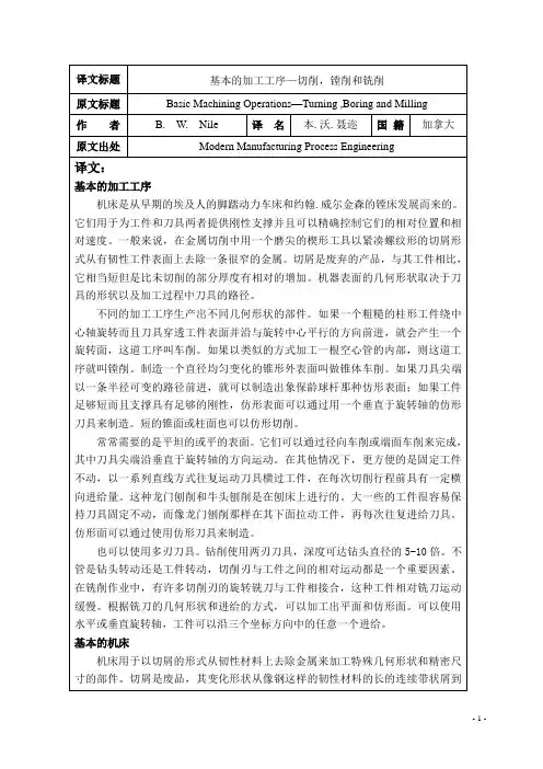

山东轻工业学院中英文翻译院系名称学生姓名专业班级指导教师二○**年五月十日Introduction of MachiningHave a shape as a processing method, all machining process for the production of the most commonly used and most important method. Machining process is a process generated shape, in this process, Drivers device on the workpiece material to be in the form of chip removal. Although in some occasions, the workpiece under no circumstances, the use of mobile equipment to the processing, however, the majority of the machining is not only supporting the workpiece also supporting tools and equipment to complete.Machining know the process has two aspects. Small group of low-cost production. For casting, forging and machining pressure, every production of a specific shape of the workpiece, even a spare part, almost have to spend the high cost of processing. Welding to rely on the shape of the structure, to a large extent, depend on effective in the form of raw materials. In general, through the use of expensive equipment and without special processing conditions, can be almost any type of raw materials, mechanical processing to convert the raw materials processed into the arbitrary shape of the structure, as long as the external dimensions large enough, it is possible. Because of a production of spare parts, even when the parts and structure of the production batch sizes are suitable for the original casting, Forging or pressure processing to produce, but usually prefer machining.Strict precision and good surface finish, machining the second purpose is the establishment of the high precision and surface finish possible on the basis of. Many parts, if any other means of production belonging to the large-scale production, Well Machining is a low-tolerance and can meet the requirements of small batch production. Besides, many parts on the production and processing of coarse process to improve its general shape of the surface. It is only necessary precision and chooses only the surface machining. For instance, thread, in addition to mechanical processing, almost no other processing method for processing. Another example is the blacksmith pieces keyhole processing, as well as training to be conducted immediately after the mechanical completion of the processing.Primary Cutting ParametersCutting the work piece and tool based on the basic relationship between the following four elements to fully describe: the tool geometry, cutting speed, feed rate, depth and penetration of a cutting tool.Cutting Tools must be of a suitable material to manufacture, it must be strong, tough, hard and wear-resistant. Tool geometry -- to the tip plane and cutter angle characteristics -- for each cutting process must be correct.Cutting speed is the cutting edge of work piece surface rate; it is inches per minute to show. In order to effectively processing, and cutting speed must adapt to the level of specific parts -- with knives. Generally, the more hard work piece material, the lower the rate.Progressive Tool to speed is cut into the work piece speed. If the work piece or tool for rotating movement, feed rate per round over the number of inches to the measurement. When the work piece or tool for reciprocating movement and feed rate on each trip through the measurement of inches. Generally, in other conditions, feed rate and cutting speed is inversely proportional to。
英文翻译原文:(一)BORING AND BORING MACHINESAs carried out on a lathe,boring produces circular internal profiles in hollow work-pieces or on a hole made by drilling or another process,Boring is done with cutting tools that are similar to those used in turning.Because the boring bar has to reach the full length of the bore,tool deflection and,therefore,maintainance of dimensional accuracy can be a significant problem.The boring bar must be sufficiently stiff—that is,made of a material with high elastic modulus,such as tungsten carbide–to minimize deflection and avoid vibration and chatter.Boring bars have been designed with capabilities for damping vibration.Although boring operations on relatively small work-pieces.Can be carried out on a lathe,boring mills are used for large work-pieces.These machines are either vertical or horizontal,and are capable of performing operations such as turning, facing,grooving,and chamfering.A vertical boring machine is similar to a lathe but has a vertical axis of work-piece rotation.The cutting tool(usually a single point made of M-2and M-3high-speed steel and C-7and C-8carbide)is mounted on the tool head,which is capable of vertical movement(for boring and turning)and radial movement(for facing),guided by the cross-rail.The head can be swiveled to produce conical(tapered)surfaces.In horizontal boring machine,the work-piece is mounted on a table that can move horizontally in both the axial and radial directions.The cutting tool is mounted on a spindle that rotates in the headstock,which is capable of both vertical and longitudinal movements.Drills,reamer,taps,and milling cutters can also be mounted on the machine spindle.Boring machine are available with a variety of features.Although work-piece diameters are generally1m-4m(3ft-12ft),work-piece as large as20m(60ft)can be machined in some vertical boring machines.Machine capacities range up to150kw (200hp).these machines are also available with computer numerical controls,which allow all movements to be programmed.With such controls,little operaror involvement is required and consistency and productivity are improved.Cutting speeds and feeds for boring are similar to those for turning.(For capabilities of boring operations)Jig borers are vertical boring machines with high–precision bearings.Although they are available in various sizes and used in tool rooms for making jigs and fixtures,they are now being replaced by more versatile numerical control machines.Design considerations for boring.Guidelines for efficient and economical boring operations are similar to those for turning.Additionally,the following factors should be considered:a.Whenever possible,through holes rather than blind holes should bespecified.(The term blind hole refers to a hole that does not go thoughthe thickness of the work-piece)b.The greater the length–to–bore-diameter ratio,the more difficult it is tohold dimensions because of the deflections of the boring bar due tocutting forces.c.Interrupted internal surfaces should be avoided.(2)Fundamentals of Machine Tools In many cases products form the primary forming processes must undergo further refinements in size and surface finish to meet their design specifications.To meet such precise tolerances the removal of small amounts of material is needed. Usually machine tools are used for such operation.In the United States material removal is a big business-in excess of$per year, including material,labor,overhead,and machine-tool shipments,is spent.Since60 percent of the mechanical and industrial engineering and technology graduates have something connection with the machining industry either through sale,design,or operation of machine shops,or working in related industry,it is wise for an engineering student to devote some time in his curriculum to studying material removal and machine tools.A machine tool provides the means for cutting tools to shape a workpiece to required dimensions;the machine supports the tool and the workpiece in a controlled relationship through the functioning of its basic members,which are as follow:(a)Bed,Structure or Frame.This is the main member which provides a basis for, and a connection between,the spindles and slides;the distortion and vibration under load must be kept to a minimum.(b)Slides and Sideways.The translation of a machine element(e.g.the slide)is normally achieved by straight-line motion under the constraint of accurate guiding surfaces(the slideway).(c)Spindles and Bearings.Angular displacements take place about an axis of rotation;the position of this axis must be constant within extremely fine limits in machine tools,and is ensured by the provision of precision spindles and bearings.(d)Power Unit.The electric motor is the universally adopted power unit for machine tools.By suitably positioning individual motors,belt and gear transmissions are reduced to a minimum.(e)Transmission Linkage.Linkage is the general term used to denote the mechanical,hydraulic,pneumatic or electric mechanisms which connect angular andlinear displacements in defined relationship.There are two broad divisions of machining operations:(a)Roughing,for which the metal removal rate,and consequently the cutting force,is high,but the required dimensional accuracy relatively low.(b)Finishing,for which the metal removal rate,and consequently the cutting force,is low,but the required dimensional accuracy and surface finish relatively high. It follows that static loads and dynamic loads,such as result form an unbalanced grindingwheel,are more significant in finishing operations than in roughing operations,The degree of precision achieved in any machining process will usually be influenced by the magnitude of the deflections,which occur as a result of the force acting.Machine tool frames are generally made in cast iron,although some may be steel casting or mild-steel fabrications.Cast iron is chosen because of its cheapness,rigidity, compressive strength and capacity for damping the vibrations set-up in machine operations,To avoid massive sections in castings,carefully designed systems of ribbing are used to offer the maximum resistance to bending and torsional stresses. Two basic types of ribbing are box and diagonal.The box formation is convenient to produce,apertures in walls permitting the positioning and extraction of cores. Diagonal ribbing provides greater torsional stiffness and yet permits swarf to fall between the sections;it is frequently used for lathe beds.The slides and slideways of a machine tool locate and guide members which move relative to each other,usually changing the position of the tool relative to workpiece.The movement generally takes the form of translation in a straight line, but is sometimes angular rotation, e.g.tilting the wheel-head of a universal thread-grinding machine to an angle corresponding which the helix angle of the workpiece thread.The basic geometric elements of slides are flat,vee,dovetail and cylinder.These elements may be used separately or combined in various ways according to the applications.Features of slideways are as follows:(a)Accuracy of Movement.Where a slide is to be displaced in a straight line, this line must lie in two mutually perpendicular planes and there must be no slide rotation.The general tolerance for straightness of machine tool slideways is 0~0.02mm per1000mm;on horizontal surfaces this tolerance may be disposed so thata convex surface results,thus countering the effect of"sag"of the slideway.(b)Means of Adjustment.To facilitate assembly,maintain accuracy and eliminate"play"between sliding members after wear has taken place,a strip is sometimes inserted in slides.This is called a ually,the gib is retained by socket-head screws passing through elongated slots;and is adjusted by grub-screws secured by lock nuts.(c)Lubrication.Slideways may be lubricated by either of the following systems:1)Intermittently through grease or oil nipples,a method suitable wheremovements are infrequent and speed low.2)Continuously e.g.by pumping through a metering valve and pipe-work to the point of application;the film of oil introduced between surfaces by these means must be extremely thin to avoid the slide“floating”.If sliding surfaces were optically flatoil would be squeezed out,resulting in the surfaces sticking.Hence in practice slide Sill"faces are either grourld using the edge of a cup wheel,or scraped.Both processes produee minulte surface depressions,which retain‘‘pocket”of oil,and complete separation of the parts may not occur at all points.(d)Protection.To maintain slideways in good order,the following conditions must be met:1)Ingress of foreign matter,e.g.swarf,must be prevented.Where this is no possible,it is desirable to have a form of slideway,which does not retain swarf,e.g. the inverted vee.2)Lubricating oil must be retained.The adhesive property of oil for use on vertical or inclined slide surface is important;oils are available which have been specially developed for this purpose.The adhesiveness of oil also preverts it being washed away by cutting fluids.3)Accidental damage must be prevented by protective guards.译文:(一)镗削加工和镗床像车床加工零件一样,镗床能在中空的工件或由钻削加工或其它工艺所加工的孔上进行内轮廓圆的加工。
英文原文Cutting process and fixture designMachine tools have evolved from the early foot-powered lathes of the Egyptians and John Wilkinson's boring mill. They are designed to provide rigid support for both the workpiece and the cutting tool and can precisely control their relative positions and the velocity of the tool with respect to the workpiece. Basically, in metal cutting, a sharpened wedge-shaped tool removes a rather narrow strip of metal from the surface of a ductile workpiece in the form of a severely deformed chip. The chip is a waste product that is considerably shorter than the workpiece from which it came but with a corresponding increase in thickness of the uncut chip. The geometrical shape of workpiece depends on the shape of the tool and its path during the machining operation.Most machining operations produce parts of differing geometry. If a rough cylindrical workpiece revolves about a central axis and the tool penetrates beneath its surface and travels parallel to the center of rotation, a surface of revolution is produced, and the operation is called turning. If a hollow tube is machined on the inside in a similar manner, the operation is called boring. Producing an external conical surface uniformly varying diameter is called taper turning, if the tool point travels in a path of varying radius, a contoured surface like that of a bowling pin can be produced; or, if the piece is short enough and the support is sufficiently rigid, a contoured surface could be produced by feeding a shaped tool normal to the axis of rotation. Short tapered or cylindrical surfaces could also be contour formed.Flat or plane surfaces are frequently required. They can be generated by radial turning or facing, in which the tool point moves normal to the axis of rotation. In other cases, it is more convenient to hold the workpiece steady and reciprocate the tool across it in a series of straight-line cuts with a crosswise feed increment before each cutting stroke. This operation is called planning and is carried out on a shaper. For larger pieces it is easier to keep the tool stationary and draw the workpiece under it as in planning. The tool is fed at each reciprocation. Contoured surfaces can be produced by using shaped tools.Multiple-edged tools can also be used. Drilling uses a twin-edged fluted tool for holes with depths up to 5 to 10 times the drill diameter. Whether thedrill turns or the workpiece rotates, relative motion between the cutting edge and the workpiece is the important factor. In milling operations a rotary cutter with a number of cutting edges engages the workpiece. Which moves slowly with respect to the cutter. Plane or contoured surfaces may be produced, depending on the geometry of the cutter and the type of feed. Horizontal or vertical axes of rotation may be used, and the feed of the workpiece may be in any of the three coordinate directions.Basic Machine ToolsMachine tools are used to produce a part of a specified geometrical shape and precise I size by removing metal from a ductile material in the form of chips. The latter are a waste product and vary from long continuous ribbons of a ductile material such as steel, which are undesirable from a disposal point of view, to easily handled well-broken chips resulting from cast iron. Machine tools perform five basic metal-removal processes: I turning, planning, drilling, milling, and grinding. All other metal-removal processes are modifications of these five basic processes. For example, boring is internal turning; reaming, tapping, and counter boring modify drilled holes and are related to drilling; bobbing and gear cutting are fundamentally milling operations; hack sawing and broaching are a form of planning and honing; lapping, super finishing. Polishing and buffing are variants of grinding or abrasive removal operations. Therefore, there are only four types of basic machine tools, which use cutting tools of specific controllable geometry: 1. lathes, 2. planers, 3. drilling machines, and 4. milling machines. The grinding process forms chips, but the geometry of the abrasive grain is uncontrollable.The amount and rate of material removed by the various machining processes may be I large, as in heavy turning operations, or extremely small, as in lapping or super finishing operations where only the high spots of a surface are removed.A machine tool performs three major functions: 1. it rigidly supports the workpiece or its holder and the cutting tool; 2. it provides relative motion between the workpiece and the cutting tool; 3. it provides a range of feeds and speeds usually ranging from 4 to 32 choices in each case.Speed and Feeds in MachiningSpeeds, feeds, and depth of cut are the three major variables for economical machining. Other variables are the work and tool materials, coolant and geometry of the cutting tool. The rate of metal removal and power required for machining depend upon these variables.The depth of cut, feed, and cutting speed are machine settings that must be established in any metal-cutting operation. They all affect the forces, the power, and the rate of metal removal. They can be defined by comparing them to the needle and record of a phonograph. The cutting speed (V) is represented by the velocity of- the record surface relative to the needle in the tone arm at any instant. Feed is represented by the advance of the needle radially inward per revolution, or is the difference in position between two adjacent grooves. The depth of cut is the penetration of the needle into the record or the depth of the grooves.Turning on Lathe CentersThe basic operations performed on an engine lathe are illustrated. Those operations performed on external surfaces with a single point cutting tool are called turning. Except for drilling, reaming, and lapping, the operations on internal surfaces are also performed by a single point cutting tool.All machining operations, including turning and boring, can be classified as roughing, finishing, or semi-finishing. The objective of a roughing operation is to remove the bulk of the material as rapidly and as efficiently as possible, while leaving a small amount of material on the work-piece for the finishing operation. Finishing operations are performed to obtain the final size, shape, and surface finish on the workpiece. Sometimes a semi-finishing operation will precede the finishing operation to leave a small predetermined and uniform amount of stock on the work-piece to be removed by the finishing operation.Generally, longer workpieces are turned while supported on one or two lathe centers. Cone shaped holes, called center holes, which fit the lathe centers are drilled in the ends of the workpiece-usually along the axis of the cylindrical part. The end of the workpiece adjacent to the tailstock is always supported by a tailstock center, while the end near the headstock may be supported by a headstock center or held in a chuck. The headstock end of the workpiece may be held in a four-jaw chuck, or in a type chuck. This method holds the workpiece firmly and transfers the power to the workpiece smoothly; the additional support to the workpiece provided by the chuck lessens the tendency for chatter to occur when cutting. Precise results can be obtained with this method if care is taken to hold the workpiece accurately in the chuck.Very precise results can be obtained by supporting the workpiece between two centers. A lathe dog is clamped to the workpiece; together they are driven by a driver plate mounted on the spindle nose. One end of the Workpiece is mecained;then the workpiece can be turned around in the lathe to machine the other end. The center holes in the workpiece serve as precise locating surfaces as well as bearing surfaces to carry the weight of the workpiece and to resist the cutting forces. After the workpiece has been removed from the lathe for any reason, the center holes will accurately align the workpiece back in the lathe or in another lathe, or in a cylindrical grinding machine. The workpiece must never be held at the headstock end by both a chuck and a lathe center. While at first thought this seems like a quick method of aligning the workpiece in the chuck, this must not be done because it is not possible to press evenly with the jaws against the workpiece while it is also supported by the center. The alignment provided by the center will not be maintained and the pressure of the jaws may damage the center hole, the lathe center, and perhaps even the lathe spindle. Compensating or floating jaw chucks used almost exclusively on high production work provide an exception to the statements made above. These chucks are really work drivers and cannot be used for the same purpose as ordinary three or four-jaw chucks.While very large diameter workpieces are sometimes mounted on two centers, they are preferably held at the headstock end by faceplate jaws to obtain the smooth power transmission; moreover, large lathe dogs that are adequate to transmit the power not generally available, although they can be made as a special. Faceplatejaws are like chuck jaws except that they are mounted on a faceplate, which has less overhang from the spindle bearings than a large chuck would have.I ntroduction of MachiningMachining as a shape-producing method is the most universally used and the most important of all manufacturing processes. Machining is a shape-producing process in which a power-driven device causes material to be removed in chip form. Most machining is done with equipment that supports both the work piece and cutting tool although in some cases portable equipment is used with unsupported workpiece.Low setup cost for small Quantities. Machining has two applications in manufacturing. For casting, forging, and press working, each specific shape to be produced, even one part, nearly always has a high tooling cost. The shapes that may he produced by welding depend to a large degree on the shapes of raw material that are available. By making use of generally high cost equipment but without special tooling, it is possible, by machining; to start with nearly any form of raw material, so tong as the exterior dimensions are great enough, and produce any desired shape from any material. Therefore .machining is usually the preferred method for producing one or a few parts, even when the design of the part would logically lead to casting, forging or press working if a high quantity were to be produced.Close accuracies, good finishes. The second application for machining is based on the high accuracies and surface finishes possible. Many of the parts machined in low quantities would be produced with lower but acceptable tolerances if produced in high quantities by some other process. On the other hand, many parts are given their general shapes by some high quantity deformation process and machined only on selected surfaces where high accuracies are needed. Internal threads, for example, are seldom produced by any means other than machining and small holes in press worked parts may be machined following the press working operations.Primary Cutting ParametersThe basic tool-work relationship in cutting is adequately described by means of four factors: tool geometry, cutting speed, feed, and depth of cut.The cutting tool must be made of an appropriate material; it must be strong, tough, hard, and wear resistant. The tool s geometry characterized by planes and angles, must be correct for each cutting operation. Cutting speed is the rate at which the work surface passes by the cutting edge. It may be expressed in feet per minute.For efficient machining the cutting speed must be of a magnitude appropriate to the particular work-tool combination. In general, the harder the work material, the slower the speed.Feed is the rate at which the cutting tool advances into the workpiece. "Where the workpiece or the tool rotates, feed is measured in inches per revolution. When the tool or the work reciprocates, feed is measured in inches per stroke, Generally, feed varies inversely with cutting speed for otherwise similar conditions.The depth of cut, measured inches is the distance the tool is set into the work. It is the width of the chip in turning or the thickness of the chip in a rectilinear cut. In roughing operations, the depth of cut can be larger than for finishing operations.The Effect of Changes in Cutting Parameters on Cutting TemperaturesIn metal cutting operations heat is generated in the primary and secondary deformation zones and these results in a complex temperature distribution throughout the tool, workpiece and chip. A typical set of isotherms is shown in figure where it can be seen that, as could be expected, there is a very large temperature gradient throughout the width of the chip as the workpiece material is sheared in primary deformation and there is a further large temperature in the chip adjacent to the face as the chip is sheared in secondary deformation. This leads to a maximum cutting temperature a short distance up the face from the cutting edge and a small distance into the chip.Since virtually all the work done in metal cutting is converted into heat, it could be expected that factors which increase the power consumed per unit volume of metal removed will increase the cutting temperature. Thus an increase in the rake angle, all other parameters remaining constant, will reduce the power per unit volume of metal removed and the cutting temperatures will reduce. When considering increase in unreformed chip thickness and cutting speed the situation is more complex. An increase in undeformed chip thicknesstends to be a scale effect where the amounts of heat which pass to the workpiece, the tool and chip remain in fixed proportions and the changes in cutting temperature tend to be small. Increase in cutting speed; however, reduce the amount of heat which passes into the workpiece and this increase the temperature rise of the chip m primary deformation. Further, the secondary deformation zone tends to be smaller and this has the effect of increasing the temperatures in this zone. Other changes in cutting parameters have virtually no effect on the power consumed per unit volume of metal removed and consequently have virtually no effect on the cutting temperatures. Since it has been shown that even small changes in cutting temperature have a significant effect on tool wear rate it is appropriate to indicate how cutting temperatures can be assessed from cutting data.The most direct and accurate method for measuring temperatures in high -speed-steel cutting tools is that of Wright &. Trent which also yields detailed information on temperature distributions in high-speed-steel cutting tools. The technique is based on the metallographic examination of sectioned high-speed-steel tools which relates microstructure changes to thermal history.Trent has described measurements of cutting temperatures and temperature distributions for high-speed-steel tools when machining a wide range of workpiece materials. This technique has been further developed by using scanning electron microscopy to study fine-scale microstructure changes arising from over tempering of the tempered martens tic matrix of various high-speed-steels. This technique has also been used to study temperature distributions in both high-speed -steel single point turning tools and twist drills.Wears of Cutting ToolDiscounting brittle fracture and edge chipping, which have already been dealt with, tool wear is basically of three types. Flank wear, crater wear, and notch wear. Flank wear occurs on both the major and the minor cutting edges. On the major cutting edge, which is responsible for bulk metal removal, these results in increased cutting forces and higher temperatures which if left unchecked can lead to vibration of the tool and workpiece and a condition where efficient cutting can no longer take place. On the minor cutting edge, which determines workpiece size and surface finish, flank wear can result in an over sized product which has poor surface finish. Under most practical cutting conditions, the tool will fail due to major flank wear before the minor flank wear is sufficiently large to result in the manufacture of an unacceptable component.Because of the stress distribution on the tool face, the frictional stress in the region of sliding contact between the chip and the face is at a maximum at the start of the sliding contact region and is zero at the end. Thus abrasive wear takes place in this region with more wear taking place adjacent to the seizure region than adjacent to the point at which the chip loses contact with the face. This result in localized pitting of the tool face some distance up the face which is usually referred to as catering and which normally has a section in the form of a circular arc. In many respects and for practical cutting conditions, crater wear is a less severe form of wear than flank wear and consequently flank wear is a more common tool failure criterion. However, since various authors have shown that the temperature on the face increases more rapidly with increasing cutting speed than the temperature on the flank, and since the rate of wear of any type is significantly affected by changes in temperature, crater wear usually occurs at high cutting speeds.At the end of the major flank wear land where the tool is in contact with the uncut workpiece surface it is common for the flank wear to be more pronounced than along the rest of the wear land. This is because of localised effects such as a hardened layer on the uncut surface caused by work hardening introduced by a previous cut, an oxide scale, and localised high temperatures resulting from the edge effect. This localised wear is usually referred to as notch wear and occasionally is very severe. Although the presence of the notch will not significantly affect the cutting properties of the tool, the notch is often relatively deep and if cutting were to continue there would be a good chance that the tool would fracture.If any form of progressive wear allowed to continue, dramatically and the tool would fail catastrophically, i. e. the tool would be no longer capable of cutting and, at best, the workpiece would be scrapped whilst, at worst, damage could be caused to the machine tool. For carbide cutting tools and for all types of wear, the tool is said to have reached the end of its useful life long before the onset of catastrophic failure. For high-speed-steel cutting tools, however, where the wear tends to be non-uniform it has been found that the most meaningful and reproducible results can be obtained when the wear is allowed to continue to the onset ofcatastrophic failure even though, of course, in practice a cutting time far less than that to failure would be used. The onset of catastrophic failure is characterized by one of several phenomena, the most common being a sudden increase in cutting force, the presence of burnished rings on the workpiece, and a significant increase in the noise level.Mechanism of Surface Finish ProductionThere are basically five mechanisms which contribute to the production of a surface which have been machined. These are:(l) The basic geometry of the cutting process. In, for example, single point turning the tool will advance a constant distance axially per revolution of the work price and the resultant surface will have on it, when viewed perpendicularly to the direction of tool feed motion, a series of cusps which will have a basic form which replicates the shape of the tool in cut.(2) The efficiency of the cutting operation. It has already been mentioned that cutting with unstable built-up-edges will produce a surface which contains hard built-up-edge fragments which will result in a degradation of the surface finish. It can also be demonstrated that cutting under adverse conditions such as apply when using large feeds small rake angles and low cutting speeds, besides producing conditions which lead to unstable built-up-edge production, the cutting process itself can become unstable and instead of continuous shear occurring in the shear zone, tearing takes place, discontinuous chips of uneven thickness are produced, and the resultant surface is poor. This situation is particularly noticeable when machining very ductile materials such as copper and aluminum.(3) The stability of the machine tool. Under some combinations of cutting conditions; workpiece size, method of clamping ,and cutting tool rigidity relative to the machine tool structure, instability can be set up in the tool which causes it to vibrate. Under some conditions this vibration will reach and maintain steady amplitude whilst under other conditions the vibration will built up and unless cutting is stopped considerable damage to both the cutting tool and workpiece may occur. This phenomenon is known as chatter and in axial turning is characterized by long pitch helical bands on the workpiece surface and short pitch undulations on the transient machined surface.(4)The effectiveness of removing swarf. In discontinuous chip production machining, such as milling or turning of brittle materials, it is expected that the chip (swarf) will leave the cutting zone either under gravity or with the assistance of a jet of cutting fluid and that they will not influence the cut surface in any way. However, when continuous chip production is evident, unless steps are taken to control the swarf it is likely that it will impinge on the cut surface and mark it. Inevitably, this marking besides looking.(5)The effective clearance angle on the cutting tool. For certain geometries of minor cutting edge relief and clearance angles it is possible to cut on the major cutting edge and burnish on the minor cutting edge. This can produce a good surface finish but, of course, it is strictly a combination of metal cutting and metal forming and is not to be recommended as a practical cutting method. However, due to cutting tool wear, these conditions occasionally arise and lead to a marked change in the surface characteristics.Limits and TolerancesMachine parts are manufactured so they are interchangeable. In other words, each part of a machine or mechanism is made to a certain size and shape so will fit into any other machine or mechanism of the same type. To make the part interchangeable, each individual part must be made to a size that will fit the mating part in the correct way. It is not only impossible, but also impractical to make many parts to an exact size. This is because machines are not perfect, and the tools become worn. A slight variation from the exact size is always allowed. The amount of this variation depends on the kind of part being manufactured. For examples part might be made 6 in. long with a variation allowed of 0.003 (three-thousandths) in. above and below this size. Therefore, the part could be 5.997 to 6.003 in. and still be the correct size. These are known as the limits. The difference between upper and lower limits is called the tolerance.A tolerance is the total permissible variation in the size of a part.The basic size is that size from which limits of size arc derived by the application of allowances and tolerances.Sometimes the limit is allowed in only one direction. This is known as unilateral tolerance.Unilateral to learning is a system of dimensioning where the tolerance (that is variation) is shown in only one direction from the nominal size. Unilateral to learning allow the changing of tolerance on a hole or shaft without seriously affecting the fit.When the tolerance is in both directions from the basic size it is known as a bilateral tolerance (plus and minus).Bilateral to learning is a system of dimensioning where the tolerance (that is variation) is split and is shown on either side of the nominal size. Limit dimensioning is a system of dimensioning where only the maximum and minimum dimensions arc shown. Thus, the tolerance is the difference between these two dimensions.Surface Finishing and Dimensional ControlProducts that have been completed to their proper shape and size frequently require some type of surface finishing to enable them to satisfactorily fulfill their function. In some cases, it is necessary to improve the physical properties of the surface material for resistance to penetration or abrasion. In many manufacturing processes, the product surface is left with dirt .chips, grease, or other harmful material upon it. Assemblies that are made of different materials, or from the same materials processed in different manners, may require some special surface treatment to provide uniformity of appearance.Surface finishing may sometimes become an intermediate step processing. For instance, cleaning and polishing are usually essential before any kind of plating process. Some of the cleaning procedures are also used for improving surface smoothness on mating parts and for removing burrs and sharp corners, which might be harmful in later use. Another important need for surface finishing is for corrosion protection in a variety of: environments. The type of protection procedure will depend largely upon the anticipated exposure, with due consideration to the material being protected and the economic factors involved.Satisfying the above objectives necessitates the use of main surface-finishing methods that involve chemical change of the surface mechanical work affecting surface properties, cleaning by a variety of methods, and the application of protective coatings, organic and metallic.In the early days of engineering, the mating of parts was achieved by machining one part as nearly as possible to the required size, machining the mating part nearly to size, and then completing its machining, continually offering the other part to it, until the desired relationship was obtained. If it was inconvenient to offer one part to the other part during machining, the final work was done at the bench by a fitter, who scraped the mating parts until the desired fit was obtained, the fitter therefore being a 'fitter' in the literal sense. J It is obvious that the two parts would have to remain together, and m the event of one having to be replaced, the fitting would have to be done all over again. In these days, we expect to be able to purchase a replacement for a broken part, and for it to function correctly without the need for scraping and other fitting operations.When one part can be used 'off the shelf' to replace another of the same dimension and material specification, the parts are said to be interchangeable. A system of interchangeability usually lowers the production costs as there is no need for an expensive, 'fiddling' operation, and it benefits the customer in the event of the need to replace worn parts.Automatic Fixture DesignTraditional synchronous grippers for assembly equipment move parts to the gripper center-line, assuring that the parts will be in a known position after they arc picked from a conveyor or nest. However, in some applications, forcing the part to the center-line may damage cither the part or equipment. When the part is delicate and a small collision can result in scrap, when its location is fixed by a machine spindle , or when tolerances are tight, it is preferable to make a gripper comply with the position of the part, rather than the other way around. For these tasks, zaytran Inc. Of Elyria, Ohio, has created the GPN series of non- synchronous, compliant grippers. Because the force and synchronizations systems of the grippers are independent, the synchronization system can be replaced by a precision slide system without affecting gripper force. Gripper sizes range from 51b gripping force and 0.2 in. stroke to 40Glb gripping force and 6in stroke. Grippers。
毕业设计(论文)外文资料翻译系部:专业:姓名:学号:外文出处:English For Electromechanical(用外文写)Engineering附件:1.外文资料翻译译文;2.外文原文。
附件1:外文资料翻译译文机床机床是用于切削金属的机器。
工业上使用的机床要数车床、钻床和铣床最为重要。
其它类型的金属切削机床在金属切削加工方面不及这三种机床应用广泛。
车床通常被称为所有类型机床的始祖。
为了进行车削,当工件旋转经过刀具时,车床用一把单刃刀具切除金属。
用车削可以加工各种圆柱型的工件,如:轴、齿轮坯、皮带轮和丝杠轴。
镗削加工可以用来扩大和精加工定位精度很高的孔。
钻削是由旋转的钻头完成的。
大多数金属的钻削由麻花钻来完成。
用来进行钻削加工的机床称为钻床。
铰孔和攻螺纹也归类为钻削过程。
铰孔是从已经钻好的孔上再切除少量的金属。
攻螺纹是在内孔上加工出螺纹,以使螺钉或螺栓旋进孔内。
铣削由旋转的、多切削刃的铣刀来完成。
铣刀有多种类型和尺寸。
有些铣刀只有两个切削刃,而有些则有多达三十或更多的切削刃。
铣刀根据使用的刀具不同能加工平面、斜面、沟槽、齿轮轮齿和其它外形轮廓。
牛头刨床和龙门刨床用单刃刀具来加工平面。
用牛头刨床进行加工时,刀具在机床上往复运动,而工件朝向刀具自动进给。
在用龙门刨床进行加工时,工件安装在工作台上,工作台往复经过刀具而切除金属。
工作台每完成一个行程刀具自动向工件进给一个小的进给量。
磨削利用磨粒来完成切削工作。
根据加工要求,磨削可分为精密磨削和非精密磨削。
精密磨削用于公差小和非常光洁的表面,非精密磨削用于在精度要求不高的地方切除多余的金属。
车床车床是用来从圆形工件表面切除金属的机床,工件安装在车床的两个顶尖之间,并绕顶尖轴线旋转。
车削工件时,车刀沿着工件的旋转轴线平行移动或与工件的旋转轴线成一斜角移动,将工件表面的金属切除。
车刀的这种位移称为进给。
车刀装夹在刀架上,刀架则固定在溜板上。
溜板是使刀具沿所需方向进行进给的机构。
机械加工切削加工中英文对照外文翻译文献中英文资料翻译英文部分The new concept of cutting processingThe nowadays cutting tool company cannot only be again the manufacture and the sales cutting tool, in order to succeed, they must be consistent with the globalization manufacture tendency maintenance, through enhances the efficiency, cooperates with the customer reduces the cost. Approaches the instantaneous global competition after this after NAFTA, the WTO time, the world company is making quickly to the same feeling, is lighter, a cheaper response. In other words, they make the product and the components contain can in high speed under revolve, as a result of the cost pressure, best, is lighter moreover must make cheaply. Obtains these goals a best way is through develops and applies the new material, but these is new and the improvement material usually all with difficulty processes. In in this kind of commercial power and the technical difficulty combination is especially prominent in the automobile and the aviation industry, and has become has the experience the cutting tool company to research and develop the department the most important driving influence.For example, takes the modular cast iron to say that, it has become the engine part and other automobiles, the agriculture the material which see day by day with the equipment and in the machine tool industry components. This kind of alloy provides the low production cost and the good machine capability combination. They are cheaper than the steel products, but has a higher intensity and toughness compared to the cast iron. But atthe same time the modular cast iron is extremely wear-resisting, has fast breaks by rubbing the cutting tool material the tendency. In this wear resistant very great degree bead luminous body content influence. Some known modular cast iron bead luminous body content higher, its resistance to wear better, moreover its machinability is worse. Moreover, the modular cast iron porosity causes off and on to cut, this even more reduces the life.May estimate that, the high degree of hardness and the high wear-resisting cutting material quality must consider the modular cast iron the high resistance to wear. And the material quality contains extremely hard TiC in fact (carbonized titanium) or TiCN (carbon titanium nitrides) thick coating when cutting speed each minute 300 meters processes the modular cast iron to prove usually is effective. But along with cutting speed increase, scrap/The cutting tool junctionplane temperature also is increasing. When has such situation, the TiC coating favors in has the chemical reaction with the iron and softens, more pressures function in anti- crescent moon hollow attrition coating. Under these conditions, hoped has one chemical stability better coating, like Al2O3 (although under low speed was inferior to TiC hard or is wear-resisting).The chemical stability becomes an important performance performance dividing line compared to the resistance to wear the factor, the speed and the temperature is decided in is processed the modular cast iron the crystal grain structure and the performance. But usually thick coating of TiCN and TiC or only ductile iron oxides in the soil coating is applied to, because the today majority of this kinds are processed the material the cutting speed in each minute 150 to 335 meters between. Is higher than each minute 300 meter applications regarding thespeed, the people to this kind of material are satisfied.In order to cause this scope performance to be most superior, the mountain high researched and developed and has promoted in view of modular cast iron processing material quality TX150. This kind of material quality has hard also the anti- distortion substrate, is very ideal regarding the processing modular cast iron. Its coating the oxide compound coating which hollowly wears by thick very wear-resisting carbon titanium nitrides and a thin anti- crescent moon, the top is thin layer TiN. This kind of coating which needs the center warm chemistry gas phase deposition using the state of the art production resistance to wear and the anti- crescent moon hollow attrition which the CVD coating complete degree of hardness moreover the tough smoothness increases (MTCVD) the craft. Substrate/The coating combination performance gives the very high anti- plastic deformation and the cutting edge micro collapses the ability, causes it to become under the normal speed to process the modular cast iron the ideal material quality.The coating ceramics also display can effectively process the modular cast iron. In the past, the aluminum oxide ceramics application which not the coating tough good such as nitriding silicon and the silicon carbide textile fiber strengthened the work piece material chemistry paralysis limit. Today but could resist the scrap distortion process through the use to have the high thermal coating cutting tool life already remarkably to increase. But certain early this domains work piece processing use aluminum oxides spread the layer crystals to have to strengthen the ceramics, today most research concentrate in the TiN coating nitriding silicon. This kind of coating can remarkably open up the tough good ceramics the application scope.When machining, the work piece has processed the surface is depends upon the cutting tool and the work piece makes the relative motion to obtain.According to the surface method of formation, the machining may divide into the knife point path law, the formed cutting tool law, the generating process three kinds.The knife point path law is depends upon the knife point to be opposite in the work piecesurface path, obtains the superficial geometry shape which the work piece requests, like the turning outer annulus, the shaping plane, the grinding outer annulus, with the profile turning forming surface and so on, the knife point path are decided the cutting tool and the work piece relative motion which provides in the engine bed;The formed cutting tool law abbreviation forming, is with the formed cutting tool which matches with the work piece final superficial outline, or the formed grinding wheel and so on processes the formed surface, like formed turning, formed milling and form grinding and so on, because forms the cutting tool the manufacture quite to be difficult, therefore only uses in processing the short formed surface generally;The generating process name rolls cuts method, is when the processing the cutting tool and the work piece do unfold the movement relatively, the cutting tool and the work piece centrode make the pure trundle mutually, between both maintains the definite transmission ratio relations, obtains the processing surface is the knife edge in this kind of movement envelope, in the gear processing rolls the tooth, the gear shaping, the shaving, the top horizontal jade piece tooth and rubs the tooth and so on to be the generating process processing.Somemachining has at the same time the knife point path law and the formed cutting tool method characteristic, like thread turning.The machining quality mainly is refers to the work piece the processing precision and the surface quality (including surface roughness, residual stress and superficial hardening).Along with the technical progress, the machining quality enhances unceasingly.The 18th century later periods, the machining precision counts by the millimeter; At the beginning of 20th century, machining precision Gao Yida 0.01 millimeter; To the 50's, the machining precision has reached a micron level; The 70's, the machining precision enhances to 0.1 micron.The influence machining quality primary factor has aspects and so on engine bed, cutting tool, jig, work piece semifinished materials, technique and processing environment.Must improve the machining quality, must take the suitable measure to the above various aspects, like reduces the engine bed work error, selects the cutting tool correctly, improves the semifinished materials quality, the reasonable arrangement craft, the improvement environmental condition and so on.Enhances the cutting specifications to enhance the material excision rate, is enhances the machining efficiency the essential way.The commonly used highly effective machining method has the high-speed cutting, the force cutting, the plasma arc heating cuts and vibrates the cutting and so on.The grinding speed is called the high-speed grinding in 45 meters/second above /doc/9c977104.html es the high-speed cutting (or grinding) both may enhance the efficiency, and mayreduce the surface roughness.The high-speed cutting (or grinding) requests the engine bed to have the high speed, thehigh rigidity, the high efficiency and the vibration-proof good craft system; Requests the cutting tool to have the reasonable geometry parameter and the convenience tight way, but also must consider the safe reliable chip breaking method.The force cutting refers to the roughing feed or cuts the deep machining greatly, uses in the turning and the grinding generally.The force turning main characteristic is the lathe tool besides the main cutting edge, but also some is parallel in the work piece has processed superficial the vice-cutting edge simultaneously to participate in the cutting, therefore may enhance to feed quantity compared to the general turning several times of even several /doc/9c977104.htmlpares with the high-speed cutting, the force cutting cutting temperature is low, the cutting tool life is long, the cutting efficiency is high; The shortcoming is processes the surface to be rough.When force cutting, the radial direction cutting force death of a parent is not suitable for to process the tall and slender work piece very much.The vibration cutting is along the cutting tool direction of feed, the attachment low frequency or the high frequency vibration machining, may enhance the cutting efficiency.The low frequency vibration cutting has the very good chip breaking effect, but does not use the chip breaking equipment, makes the knife edge intensity to increase, time the cutting total power dissipation compared to has the chip breaking installment ordinary cutting to reduce about 40%.The high frequency vibration cutting also called the ultrasonic wave vibration cutting, is helpful in reduces between the cutting tool and the work piece friction, reduces the cutting temperature, reduces the cuttingtool the coherence attrition, thus the enhancement cutting efficiency and the processing surface quality, the cutting tool life may enhance 40% approximately.To lumber, plastic, rubber, glass, marble, granite and so on nonmetallic material machining, although is similar with the metal material cutting, but uses the cutting tool, the equipment and the cutting specifications and so on has the characteristic respectively.The lumber product machining mainly carries in each kind of joiner's bench, its method mainly has: The saw cuts, digs cuts, the turning, the milling, drills truncates with the polishing and so on.The plastic rigidity is worse than the metal, the easy bending strain, the thermoplastic thermal conductivity to be in particular bad, easy to elevate temperature the conditioning.When cutting plastic, suitably with the high-speed steel or the hard alloy tools, selects the small to feed quantity and the high cutting speed, and uses compressed air cooling.If the cutting tool is sharp, the angle is appropriate, may produce the belt-shaped scrap, easy to carry off the quantity of heat.Glass (including semiconducting material and so on germanium, silicon) but degree of hardness high brittleness is big.To methods and so on glass machining commonly used cutting, drill hole, attrition and polishing.T o thickness in three millimeters following glass plates, the simple cutting method is with the diamond or other hard materials, in glass surface manual scoring, the use scratch place stress concentration, then uses the hand to break off.To the marble, the granite and the concrete and so on the hard material processing, mainly uses methods and so on cutting, turning, drill hole, shaping, attrition and polishing.When cuttingthe available circular saw blade adds the grinding compound and the water; The outer annulus and the end surface may use the negative rake the hard alloy lathe tool, by 10~30 meter/minute cutting speed turning; Drills a hole the available hard alloy drill bit; The big stone material plane available hard alloy planing tool or rolls cuts planing tool shaping; The precise smooth surface, available three mutually for the datum to the method which grinds, or the grinding and the polishing method obtains.Cutting tool in hot strong alloy applicationThe aviation processing also changes rapidly. For example, nickel base heat-resisting alloy like several years ago the most people had not heard Rene88 now occupies to the aircraft engine manufacture uses the total metal quantity 10~25%. Has very good showing and the commercial reason regarding this. For example, these heat strong alloy will be able to increase the engine endurance moreover to permit the small engine work on the big airplane, that will enhance the combustion efficiency and reduces the operation cost. These tough good materials also present the expense on the cutting tool. Their thermal stability causes on the knife point the temperature to be higher, thus reduced the cutting tool life. Similarly, in these alloy carbide pellet remarkably increased the friction, thus reduces the cutting tool life.As a result of changes in these conditions, can be very pleased to have processed many titanium alloys and nickel-based alloy materials C-2 hard metal alloys, in the application to today's cutting edge of blade to the crushing and cutting depth of the trench lines badly worn. But using the latest high-temperature processing of small particles hard metal alloys to be effective, cutlery life improved, but more importantly to enhance thereliability of applications in high-temperature alloys. Small particles hard metal than traditional hard metal materials higher compression strength and hardness, only a small increase in the resilience of the cost. And resulted in high temperature alloy processing than traditional hard metal resistance common failure mode more effective.PVD (physical gas phase deposition) coating also by certificate effective processing heat-resisting alloy. TiN (titanium nitrides) the PVD coating was uses and still was most early most receives welcome. Recently, TiAlN (nitrogen calorization titanium) and TiCN (carbontitanium nitrides) the coating also could very good use. In the past the TiAlN coating application scope and TiN compared the limit to be more. But after the cutting speed enhances them is a very good choice, enhances the productivity in these applications to reach 40%. On the other hand, is decided under the low cutting speed in coating superficial operating mode TiAlN can cause to accumulate the filings lump afterwards, micro collapses with the trench attrition.Recently, used in the heat-resisting alloy application material quality already developing, these coating but became by several combinations. The massive laboratories and the scene test has already proven this kind of combination and other any kind of sole coating compares in time the very wide scope application is very effective. Therefore aims at the heat-resisting alloy application the PVD compound coating possibly to become the focal point which the hard alloy new material quality research and development continues. With the MTCVD coating, the coating ceramics gather in the same place, they hopefully become a more effective processing to research and develop newly are moredifficult to process the work piece material the main impact strength.Dry processingIncluding the refrigerant question is technical and the commercial expansion industrial production tendency another domain which the cutting tool makes. North America and the European strict refrigerant management request and the biggest three automobile manufacturer forces them the core supplier to obtain the ISO14000 authentication (the ISO9000 environment management edition), this causes the refrigerant processing cost rise. To the car company and their core supplier said obviously one of responses which welcome is in the specific processing application avoids completely the refrigerant the use. This kind did the processing the new world to propose a series of challenges for the cutting tool supplier.Recently, already appeared some to concern this topic to promulgate the speed, to enter for, the coating chemical composition and other parameters very substantial comprehensive nature very strong useful technical papers. Wants to concentrate the elaboration in here me "does the processing viewpoint" in the operation and commercial meaning automobile manufacturer new.The metal working jobholders can the very good understanding related refrigerant use question, but majority cannot understand concerns except the technical challenge (for example row of filings) beside does the processing question in the cutting tool - work piece contact face between. Usually may observe to the refrigerant disperser scrap which flows out, but the pressure surpasses 3,000 pounds/An inch 2 high speed refrigerant also can help to break the filings, specially soft alsothe continual scrap can cause in the cutting tool - work piece contact face trouble.Uses does the cutting craft the components result is the engine bed uses the wet typeprocessing components to be hotter than. Whether before you do allow them to survey in the open-air natural cooling? If processes newly the hot components put frequently to the turnover box, elevates the environment temperature, whether components full cooling and just right enough permission precision examination? Also has the handling side several dozens on hundred components to be able to operate the worker to increase the extra burden.With many cutting tools/The work piece technical question same place, these latent questions need to state whether dryly adds the ability line. Luckily, has very many ways to elaborate these questions. For example, the compressed air was proven row of filings becomes the question in very many applications the situation to have the successful echo.Another plan is called MQL (minimum lubrication) a technology, it replaces the traditional refrigerant by the application the quite few oil mists constitution. This is a recognition compromise plan, this kind of minimum technology can large scale reduce the refrigerant the headache matter, moreover the smooth finish which processes in many applications very is also good. This domain still had very many research to do, moreover the cutting tool company positively participated in such research was absolutely essential. If they will not do fall behind the competitor, will be at the disadvantageous position.In the factory the special details design other perhaps betterplan according to the world in. The manufacturing industry jobholders possibly still could ask why they do have to use recent development the technology to replace the refrigerant method diligently which the tradition already an experience number generation of person improved enhances, because implemented especially does the experiment and the defeat which the processing or the subarid processing produced possibly causes the higher short-term cutting tool cost. The concise answer is when the bit probably accounts for the model processing components cost 3%, the refrigerant cost (from purchases to maintenance, storage, processing) can account for the components cost 15%.Perhaps does the dry processing is not all suits to each application, but above discusses likely other processing questions are same, needs from a wider operation, the environment and the commercial angle appraises. Will be able to help the cutting tool company which the customer will do this to have the competitive advantage, but these will not be able to provide unceasingly is in the passive position.Cutting tool and nanotechnologyCan fiercely change the cutting tool industry the enchanting new domain is the miniature manufacture, or the processing small granule forms the product which needs. Must refer to is its here does not have about the cutting tool miniature manufacture first matter; Second must say the matter is it is not remote.Why the miniature manufacture and are the cutting tool related. Because most main is theparticle size smaller, the hard alloy toughness of material better also is more wear-resisting. (Some experts define with the nanometer level pellet for are smaller than 0.2 mu m, but otherpeople persisted a nanometer pellet had to be smaller than the hard alloy tools prototype which 0.1 mu m) made already to complete and the test,It is said that wear resistant theatrically increase. The question is the nanometer level hard alloy pellet cannot depend on the smashing big material formation, they are certain through the smaller material constitution, but processes the molecular level granule is not easy and the economical matter.中文部分切削加工新概念现今的刀具公司再也不能只是制造和销售刀具,为了成功,他们必须与全球化制造趋势保持一致,通过提高效率、同客户合作来降低成本。
机床加工外文翻译参考文献(文档含中英文对照即英文原文和中文翻译)基本加工工序和切削技术基本加工的操作机床是从早期的埃及人的脚踏动力车和约翰·威尔金森的镗床发展而来的。
它们为工件和刀具提供刚性支撑并可以精确控制它们的相对位置和相对速度。
基本上讲,金属切削是指一个磨尖的锲形工具从有韧性的工件表面上去除一条很窄的金属。
切屑是被废弃的产品,与其它工件相比切屑较短,但对于未切削部分的厚度有一定的增加。
工件表面的几何形状取决于刀具的形状以及加工操作过程中刀具的路径。
大多数加工工序产生不同几何形状的零件。
如果一个粗糙的工件在中心轴上转动并且刀具平行于旋转中心切入工件表面,一个旋转表面就产生了,这种操作称为车削。
如果一个空心的管子以同样的方式在内表面加工,这种操作称为镗孔。
当均匀地改变直径时便产生了一个圆锥形的外表面,这称为锥度车削。
如果刀具接触点以改变半径的方式运动,那么一个外轮廓像球的工件便产生了;或者如果工件足够的短并且支撑是十分刚硬的,那么成型刀具相对于旋转轴正常进给的一个外表面便可产生,短锥形或圆柱形的表面也可形成。
平坦的表面是经常需要的,它们可以由刀具接触点相对于旋转轴的径向车削产生。
在刨削时对于较大的工件更容易将刀具固定并将工件置于刀具下面。
刀具可以往复地进给。
成形面可以通过成型刀具加工产生。
多刃刀具也能使用。
使用双刃槽钻钻深度是钻孔直径5-10倍的孔。
不管是钻头旋转还是工件旋转,切削刃与工件之间的相对运动是一个重要因数。
在铣削时一个带有许多切削刃的旋转刀具与工件接触,工件相对刀具慢慢运动。
平的或成形面根据刀具的几何形状和进给方式可能产生。
可以产生横向或纵向轴旋转并且可以在任何三个坐标方向上进给。
基本机床机床通过从塑性材料上去除屑片来产生出具有特别几何形状和精确尺寸的零件。
后者是废弃物,是由塑性材料如钢的长而不断的带状物变化而来,从处理的角度来看,那是没有用处的。
很容易处理不好由铸铁产生的破裂的屑片。
(文档含英文原文和中文翻译)中英文对照外文翻译英文原文Selection of optimum tool geometry and cutting conditionsusing a surface roughness prediction model for end milling Abstract Influence of tool geometry on the quality of surface produced is well known and hence any attempt to assess the performance of end milling should include the tool geometry. In the present work, experimental studies have been conducted to see the effect of tool geometry (radial rake angle and nose radius) and cutting conditions (cutting speed and feed rate) on the machining performance during end milling of medium carbon steel. The first and second ordermathematical models, in terms of machining parameters, were developed for surface roughness prediction using response surface methodology (RSM) on the basis of experimental results. The model selected for optimization has been validated with the Chi square test. The significance of these parameters on surface roughness has been established with analysis of variance. An attempt has also been made to optimize the surface roughness prediction model using genetic algorithms (GA). The GA program gives minimum values of surface roughness and their respective optimal conditions.1 IntroductionEnd milling is one of the most commonly used metal removal operations in industry because of its ability to remove material faster giving reasonably good surface quality. It is used in a variety of manufacturing industries including aerospace and automotive sectors, where quality is an important factor in the production of slots, pockets, precision moulds and dies. Greater attention is given to dimensional accuracy and surface roughness of products by the industry these days. Moreover, surface finish influences mechanical properties such as fatigue behaviour, wear, corrosion, lubrication and electrical conductivity. Thus, measuring and characterizing surface finish can be considered for predicting machining performance.Surface finish resulting from turning operations has traditionally received considerable research attention, where as that of machining processes using multipoint cutters, requires attention by researchers. As these processes involve large number of parameters, it would be difficult to correlate surface finish with other parameters just by conducting experiments. Modelling helps to understand this kind of process better. Though some amount of work has been carried out to develop surface finish prediction models in the past, the effect of tool geometry has received little attention. However, the radial rake angle has a major affect on the power consumption apart from tangential and radial forces. It also influences chip curling and modifies chip flow direction. In addition to this, researchers [1] have also observed that the nose radius plays a significant role in affecting the surface finish. Therefore the development of a good model should involve the radial rake angle and nose radius along with other relevant factors.Establishment of efficient machining parameters has been a problem that has confronted manufacturing industries for nearly a century, and is still the subject of many studies. Obtaining optimum machining parameters is of great concern in manufacturing industries, where the economy of machining operation plays a key role in the competitive market. In material removal processes, an improper selection of cutting conditions cause surfaces with high roughness anddimensional errors, and it is even possible that dynamic phenomena due to auto excited vibrations may set in [2]. In view of the significant role that the milling operation plays in today’s manufacturing world, there is a need to optimize the machining parameters for this operation. So, an effort has been made in this paper to see the influence of tool geometry (radial rake angle and nose radius) and cutting conditions (cutting speed and feed rate) on the surface finish produced during end milling of medium carbon steel. The experimental results of this work will be used to relate cutting speed, feed rate, radial rake angle and nose radius with the machining response i.e. surface roughness by modelling. The mathematical models thus developed are further utilized to find the optimum process parameters using genetic algorithms.2 ReviewProcess modelling and optimization are two important issues in manufacturing. The manufacturing processes are characterized by a multiplicity of dynamically interacting process variables. Surface finish has been an important factor of machining in predicting performance of any machining operation. In order to develop and optimize a surface roughness model, it is essential to understand the current status of work in this area.Davis et al. [3] have investigated the cutting performance of five end mills having various helix angles. Cutting tests were performed on aluminium alloy L 65 for three milling processes (face, slot and side), in which cutting force, surface roughness and concavity of a machined plane surface were measured. The central composite design was used to decide on the number of experiments to be conducted. The cutting performance of the end mills was assessed using variance analysis. The affects of spindle speed, depth of cut and feed rate on the cutting force and surface roughness were studied. The investigation showed that end mills with left hand helix angles are generally less cost effective than those with right hand helix angles. There is no significant difference between up milling and down milling with regard tothe cutting force, although the difference between them regarding the surface roughness was large. Bayoumi et al.[4] have studied the affect of the tool rotation angle, feed rate and cutting speed on the mechanistic process parameters (pressure, friction parameter) for end milling operation with three commercially available workpiece materials, 11 L 17 free machining steel, 62- 35-3 free machining brass and 2024 aluminium using a single fluted HSS milling cutter. It has been found that pressure and friction act on the chip – tool interface decrease with the increase of feed rate and with the decrease of the flow angle, while the cutting speed has a negligible effect on some of the material dependent parameters. Process parameters are summarized into empirical equations as functions of feed rate and tool rotation angle for each work material. However,researchers have not taken into account the effects of cutting conditions and tool geometry simultaneously; besides these studies have not considered the optimization of the cutting process.As end milling is a process which involves a large number f parameters, combined influence of the significant parameters an only be obtained by modelling. Mansour and Abdallaet al. [5] have developed a surface roughness model for the end milling of EN32M (a semi-free cutting carbon case hardening steel with improved merchantability). The mathematical model has been developed in terms of cutting speed, feed rate and axial depth of cut. The affect of these parameters on the surface roughness has been carried out using response surface methodology (RSM). A first order equation covering the speed range of 30–35 m/min and a second order equation covering the speed range of 24–38 m/min were developed under dry machining conditions. Alauddin et al. [6] developed a surface roughness model using RSM for the end milling of 190 BHN steel. First and second order models were constructed along with contour graphs for the selection of the proper combination of cutting speed and feed to increase the metal removal rate without sacrificing surface quality. Hasmi et al. [7] also used the RSM model for assessing the influence of the workpiece material on the surface roughness of the machined surfaces. The model was developed for milling operation by conducting experiments on steel specimens. The expression shows, the relationship between the surface roughness and the various parameters; namely, the cutting speed, feed and depth of cut. The above models have not considered the affect of tool geometry on surface roughness.Since the turn of the century quite a large number of attempts have been made to find optimum values of machining parameters. Uses of many methods have been reported in the literature to solve optimization problems for machining parameters. Jain and Jain [8] have used neural networks for modeling and optimizing the machining conditions. The results have been validated by comparing the optimized machining conditions obtained using genetic algorithms. Suresh et al. [9] have developed a surface roughness prediction model for turning mild steel using a response surface methodology to produce the factor affects of the individual process parameters. They have also optimized the turning process using the surface roughness prediction model as the objective function. Considering the above, an attempt has been made in this work to develop a surface roughness model with tool geometry and cutting conditions on the basis of experimental results and then optimize it for the selection of these parameters within the given constraints in the end milling operation.3 MethodologyIn this work, mathematical models have been developed using experimental results with the help of response surface methodolog y. The purpose of developing mathematical models relating the machining responses and their factors is to facilitate the optimization of the machining process. This mathematical model has been used as an objective function and the optimization was carried out with the help of genetic algorithms.3.1 Mathematical formulationResponse surface methodology (RSM) is a combination of mathematical and statisticaltechniques useful for modelling and analyzing the problems in which several independent variables influence a dependent variable or response. The mathematical models commonly used are represented by:where Y is the machining response, ϕ is the response function and S, f , α, r are milling variables and ∈ is the error which is normally distributed about the observed response Y with zero mean.The relationship between surface roughness and other independent variables can be represented as follows, where C is a constant and a, b, c and d are exponents.To facilitate the determination of constants and exponents, this mathematical model will have to be linearized by performing a logarithmic transformation as follows:The constants and exponents C, a, b, c and d can be determined by the method of leastsquares. The first order linear model, developed from the above functional relationship using least squares method, can be represented as follows:where Y1 is the estimated response based on the first-order equation, Y is the measured surface roughness on a logarithmic scale, x0 = 1 (dummy variable), x1, x2, x3 and x4 arelogarithmic transformations of cutting speed, feed rate, radial rake angle and nose radius respectively, ∈ is the experimental error and b values are the estimates of corresponding parameters.The general second order polynomial response is as given below:where Y2 is the estimated response based on the second order equation. The parameters, i.e. b0, b1, b2, b3, b4, b12, b23, b14, etc. are to be estimated by the method of least squares. Validity of the selected model used for optimizing the process parameters has been tested with the help of statistical tests, such as F-test, chi square test, etc. [10].3.2 Optimization using genetic algorithmsMost of the researchers have used traditional optimization techniques for solving machining problems. The traditional methods of optimization and search do not fare well over a broad spectrum of problem domains. Traditional techniques are not efficient when the practical search space is too large. These algorithms are not robust. They are inclined to obtain a local optimal solution. Numerous constraints and number of passes make the machining optimization problem more complicated. So, it was decided to employ genetic algorithms as an optimization technique. GA come under the class of non-traditional search and optimization techniques. GA are different from traditional optimization techniques in the following ways:1.GA work with a coding of the parameter set, not the parameter themselves.2.GA search from a population of points and not a single point.3.GA use information of fitness function, not derivatives or other auxiliary knowledge.4.GA use probabilistic transition rules not deterministic rules.5.It is very likely that the expected GA solution will be the global solution.Genetic algorithms (GA) form a class of adaptive heuristics based on principles derived from the dynamics of natural population genetics. The searching process simulates the natural evaluation of biological creatures and turns out to be an intelligent exploitation of a random search. The mechanics of a GA is simple, involving copying of binary strings. Simplicity of operation and computational efficiency are the two main attractions of the genetic algorithmic approach. The computations are carried out in three stages to get a result in one generation or iteration. The three stages are reproduction, crossover and mutation.In order to use GA to solve any problem, the variable is typically encoded into a string (binary coding) or chromosome structure which represents a possible solution to the given problem. GA begin with a population of strings (individuals) created at random. The fitness of each individual string is evaluated with respect to the given objective function. Then this initial population is operated on by three main operators – reproduction cross over and mutation – to create, hopefully, a better population. Highly fit individuals or solutions are given the opportunity to reproduce by exchanging pieces of their genetic information, in the crossover procedure, with other highly fit individuals. This produces new “offspring” solutions, which share some characteristics taken from both the parents. Mutation is often applied after crossover by altering some genes (i.e. bits) in the offspring. The offspring can either replace the whole population (generational approach) or replace less fit individuals (steady state approach). This new population is further evaluated and tested for some termination criteria. The reproduction-cross over mutation- evaluation cycle is repeated until the termination criteria are met.中文翻译选择最佳工具,几何形状和切削条件利用表面粗糙度预测模型端铣刀具几何形状对工件表面质量产生的影响是人所共知的,因此,任何成型面端铣摘要: 刀具几何形状对工件表面质量产生的影响是人所共知的,因此,任何成型面端铣设计应包括刀具的几何形状。
外文翻译专业机械设计制造及其自动化学生姓名闻志祥班级 B 机制 023 学号 021******* 指导教师刘道标钻削与镗削Addison-Wesley pub.Co.闻志祥 译摘要:通过驱动刀具能在工件上钻出通孔或盲孔,钻刀是正对着工件绕着自己的轴线旋转。
当然,刀具从其轴线向外的切削距离应和需加工的孔的半径相等。
在实际生产中,是采用关于同一轴线对称的两切削刀刃的刀具。
钻削既可被应用于手工也可用于钻床中。
钻床在尺寸和结构上有所不同。
然而,当工件被牢固地安装好后,钻刀总是绕着自己的轴线旋转。
这是和在车床上钻孔是相反的。
镗孔是扩大以前钻削或镗削好了的孔。
镗孔能够消除钻空加工时孔所产生的偏心,使孔扩大到需铰削的尺寸。
下面是对钻削、钻床分类和镗孔的简要介绍。
关键词:钻削、镗削、钻床、钻削刀具、镗刀、钻床的分类钻削刀具在钻削操作中,采用的是一种柱形的螺旋式刀具,被称之为钻刀。
钻刀有一条或两条切削刃和相应的出屑槽,出屑槽呈直线或螺旋线形。
出屑槽的作用是为在钻削过程中产生的切屑提供一个通道,同时也是便于润滑剂和冷却剂到达钻刀的切削刃和工件的被加工表面。
以下是普通刀具的概括论述:图4.1麻花钻。
麻花钻是最普通的一类钻刀。
麻花钻有两条切削刃和两条螺旋线形的出屑槽,出屑槽连续地围绕分布在整个钻体上(如图 4.1)。
钻刀除了钻体部分,还有钻颈和钻柄,钻柄可以是圆柱形,也可以是锥行。
在后者的情况下,钻柄是通过柄舌钻体顶角 楔边 死顶尖出屑槽 螺旋角 颈部 柄部出屑槽刀刃刃带 后刃面出屑槽刀刃 刃带柄舌的楔形作用安装在主轴的锥形钻套中,柄舌是安装在主轴钻套的狭槽中,这样钻刀和主轴形成一个整体来传递旋转运动。
在另一方面,圆柱形钻柄是被安装在钻夹头里,然后,以安装锥形钻柄的方法将其安装进主轴的钻套中。
从图 4.1 可以看出,两条切削边被称为刀刃,两条切削刃是通过楔子连接在一起。
麻花钻还有两条刃带,其能在钻削操作中对刀具起正确的导向和定位的作用。
中国地质大学长城学院本科毕业设计外文资料翻译系别:工程技术系专业:机械制造设计及其自动化姓名:李旭学号: 052115012015年 4 月 2 日英文翻译原文:(一)镗削加工和镗床像车床加工零件一样,镗床能在中空的工件或由钻削加工或其它工艺所加工的孔上进行内轮廓圆的加工。
镗削是由那些类似车削的刀具完成的。
因为镗头必须达到镗杆的全长,刀具将发生弯曲,因此,尺寸精度的保持性成为了一个重大问题。
镗杆必须有足够的刚度——刀杆是由较高弹性模量的材料制造的,比如碳化钨(硬质合金)——去减小弯曲和避免摇动和振动。
镗杆被设计有减振的能力。
镗床既能加工在车床上加工的较小工件,镗铣床又能加工巨大的工件。
这类机械既有立式的又有卧式的并且能够完成如:车削、车端面、切槽、和倒角。
一台立式的镗床类似一台车床,但它有一根垂直的工件旋转轴。
刀具(通常用于切削的单独切削点是由M-2和M-3高速钢和C-8硬质合金制造的)被安装于能垂直运动(用于镗削和车削)和径向运动(用于车端面)并由十字导轨导向的刀头上。
刀头能够旋转去加工圆锥形表面。
在卧式镗床上工件被装夹在能在水平面内两个轴向和径向上移动的工作台上,刀具被安装于能做垂直和纵向两方向上运动的主轴箱上。
钻头、铰刀、螺纹刀和铣刀都能安装于机床主轴上。
镗床具有许多优良的性能,它所加工工件的直径是1m-4m(3ft-12ft),工件尺寸达到20m(60ft)的可在专用的立式镗床上加工。
机床功率范围可达到150kw(200hp)。
这些可用于所有运动都能编程的数字控制加工。
利用这些控制,只需要很少的相关操作,并且稳定性和生产率大大提高了。
镗床的切削速度和进给速度和车床比较相似。
坐标镗床是属于具有较高精度支撑的立式镗床。
尽管它们可用于各类尺寸的工件加工和拥有夹紧合安装的刀具空间。
它们正被多功能的数控机床取代。
镗床的设计要求:导轨的效率,类似于车削的经济型操作,另外,应该考虑以下因素:a.无论何时,应尽可能注意是加工通孔而并盲孔。
(盲孔系列是指那些没有穿国工件厚度的孔)b.应该控制径向进给速率,很难去支撑径向,因为切削力引起镗杆的弯曲变形。
c.应该避免交叉的内表面加工。
(2)机床基础为了满足规定的设计规格,大多数情况下初步加工的产品都必须再经过进一步的尺寸和表面的精加工。
要达到这样的精确规定公差的要求,少量材料需要被切除掉,而机床通常就是用于此种操作。
在美国,材料切除是一项大业务——每年这方面的支出超过36×109美元,包括材料、劳力和机床运输。
60%的机械工程和工业工程毕业生都通过贸易、设计、机械修理工厂,或通过在相关行业工作而与机械工业密不可分,因而如果他们花费一定的时间精力来学习这个领域中的材料切除和机床技术的话会是很明智的选择。
机床提供切割工具的方式,以使工件成型,达到规定的尺寸;此种机器依靠其基础部件的运作来掌握工具和工件之间的联系。
其基础部件的运作如下:①.床身、构造和框架。
这三种主要的部件为锭子和滑移的基础,并将它们联系起来;操作中的变形和震动必须尽量避免。
②.滑移与滑轨。
机械部件(如滑移)的转换通常是通过在精密的指导表面(滑轨)的控制下做直线运动而完成的。
③.锭子与轴承。
角位移是围绕一个旋转轴线发生的;这个转轴的位置必须一直处于严格精确的限制之中,并由精密锭子和轴承提供保障。
④.动力仪器。
电动机是被广泛应用于机床的动力仪器。
通过将各电动机放置于合适的位置,传输带和齿轮运输会被降低到最低限度。
⑤.传输联接。
联接是一个通常用来指机械驱动的、水压驱动的、气压驱动的和电力驱动的机械装置,将有角移置和直线移置联系起来,使其符合规定。
加工操作大体上分为两类:①. 粗加工。
其金属切除率高且由此导致的切除力较大,但规定的尺寸精度相对较低。
②. 精加工。
其金属切除率低且由此导致的切除力较小,但规定的尺寸精度相对较高。
静载荷及动载荷,如处于非平衡状态的砂轮所导致的结果,自然在精加工方面比在粗加工操作方面更为重要。
任何加工过程所达到的精确度通常会受到偏差大小的影响,这种影响是是操作动力的结果。
机床框架通常由铸铁制造,虽然有些机床可能为钢铸件或低碳钢结构。
选择铸铁是因为其价格、硬度、耐压强度及减少加工操作中的震动的能力。
为了避免铸件出现轻重不均的部分,精心设计的肋材构架系统被采用,最大可能地抵抗造成弯曲和变形的压力。
两种肋材构架分别为箱形和对角线形。
箱形结构便于生产,因为壁上的孔径允许核心的定位和抽取。
对角线楞条配置则提供更大的抗纽刚度并允许金属屑从部件当中的孔隙落出,因此经常被用于机床。
车床的滑移和滑轨指引并且为相互影响运动的部件定位,通常根据工件更改车床的位置。
运动一般采取直线运动的形式,但有时是旋转,例如,对应于工件的螺纹螺旋角方向而转动万能螺纹磨床上的砂轮头的一个角度。
基本的对称滑移部件为扁平、V形、燕尾槽形及汽缸形。
这些部件既可单独使用又可根据用途以不同方式组合使用。
滑轨的特征如下:⒈如果滑移要在一条直线上移动位置,这条直线必须位于两个相互垂直的平面之间且必须没有滑动旋转。
⒉机床滑轨的直线性规定公差一般介于0~0.02mm/100mm之间;在水平表面此公差可以被处理以得到凸形表面这样就可以抵消滑轨下沉的作用。
⒊润滑油。
滑轨可能被以下两种系统中的任何一种润滑:⑴.间歇通过油脂或油嘴润滑。
这种方法适合运作不频繁和速度不高的情况。
⑵.持续润滑,如通过计量阀和管道根据需要抽取;通过这些方法操作的表面之间的润滑油薄膜必须非常薄,以避免滑移漂浮。
如果滑移表面是镜平面,油就会被挤出,使表面粘接。
因此实际操作中滑移表面不是被杯状轮边缘压平,就是被刮去。
两种操作过程都会产生微小的表面凹痕,这种凹痕会导致少量润油存留,而且零件的完全分离可能不会总是发生;因此,滑移的正确定位得到保留。
⒋保护。
为了维护滑轨,使其正常工作,必须满足如下条件:⑴.必须避免外来物质如铁屑的进入。
如果这种条件不可能满足,则应该采用不会滞留铁屑的,如倒V形的滑移。
⑵.润滑油必须保留。
润滑油在垂直的或倾斜滑移表面上的粘性特质非常重要;特制的润滑油市场有售。
润滑油的粘性同时能防止其被切削液冲走。
⑶.必须防止由保护装置导致的意外损坏。
译文:(一)BORING AND BORING MACHINESAs carried out on a lathe, boring produces circular internal profiles in hollow work-pieces or on a hole made by drilling or another process, Boring is done with cutting tools that are similar to those used in turning. Because the boring bar has to reach the full length of the bore, tool deflection and, therefore, maintainance of dimensional accuracy can be a significant problem.The boring bar must be sufficiently stiff—that is, made of a material with high elastic modulus, such as tungsten carbide –to minimize deflection and avoid vibration and chatter. Boring bars have been designed with capabilities for damping vibration.Although boring operations on relatively small work-pieces. Can be carried out on a lathe, boring mills are used for large work-pieces. These machines are either vertical or horizontal, and are capable of performing operations such as turning, facing, grooving, and chamfering. A vertical boring machine is similar to a lathe but has a vertical axis of work-piece rotation.The cutting tool (usually a single point made of M-2 and M-3 high-speed steel and C-7 and C-8 carbide) is mounted on the tool head, which is capable of vertical movement (for boring and turning) and radial movement (for facing), guided by the cross-rail. The head can be swiveled to produce conical (tapered) surfaces.In horizontal boring machine, the work-piece is mounted on a table that can move horizontally in both the axial and radial directions. The cutting tool is mounted on a spindle that rotates in the headstock, which is capable of both vertical and longitudinal movements. Drills, reamer, taps, and milling cutters can also be mounted on the machine spindle.Boring machine are available with a variety of features. Although work-piece diameters are generally 1 m-4 m(3ft-12ft),work-piece as large as 20 m(60ft) can be machined in some vertical boring machines. Machine capacities range up to 150 kw (200hp).these machines are also available with computer numerical controls, which allow all movements to be programmed. With such controls, little operaror involvement is required and consistency and productivity are improved. Cutting speeds and feeds for boring are similar to those forturning.(For capabilities of boring operations)Jig borers are vertical boring machines with high –precision bearings. Although they are available in various sizes and used in tool rooms for making jigs and fixtures, they are now being replaced by more versatile numerical control machines.Design considerations for boring. Guidelines for efficient and economical boring operations are similar to those for turning. Additionally, the following factors should be considered:a.Whenever possible, through holes rather than blind holes should bespecified.(The term blind hole refers to a hole that does not gothough the thickness of the work-piece )b.The greater the length –to –bore-diameter ratio, the more difficult itis to hold dimensions because of the deflections of the boring bardue to cutting forces.c.Interrupted internal surfaces should be avoided.(2)Fundamentals of Machine ToolsIn many cases products form the primary forming processes must undergo further refinements in size and surface finish to meet their design specifications. To meet such precise tolerances the removal of small amounts of material is needed. Usually machine tools are used for such operation.In the United States material removal is a big business-in excess of $ per year, including material, labor, overhead, and machine-tool shipments, is spent. Since 60 percent of the mechanical and industrial engineering and technology graduates have something connection with the machining industry either through sale, design, or operation of machine shops, or working in related industry, it is wise for an engineering student to devote some time in his curriculum to studying material removal and machine tools.A machine tool provides the means for cutting tools to shape a workpieceto required dimensions; the machine supports the tool and the workpiece in a controlled relationship through the functioning of its basic members, which are as follow:(a) Bed, Structure or Frame. This is the main member which provides a basis for, and a connection between, the spindles and slides; the distortion and vibration under load must be kept to a minimum.(b) Slides and Sideways. The translation of a machine element (e.g. the slide) is normally achieved by straight-line motion under the constraint of accurate guiding surfaces (the slideway).(c) Spindles and Bearings. Angular displacements take place about an axis of rotation; the position of this axis must be constant within extremely fine limits in machine tools, and is ensured by the provision of precision spindles and bearings.(d) Power Unit. The electric motor is the universally adopted power unit for machine tools. By suitably positioning individual motors, belt and gear transmissions are reduced to a minimum.(e) Transmission Linkage. Linkage is the general term used to denote the mechanical, hydraulic, pneumatic or electric mechanisms which connect angular and linear displacements in defined relationship.There are two broad divisions of machining operations:(a) Roughing, for which the metal removal rate, and consequently the cutting force, is high ,but the required dimensional accuracy relatively low .(b) Finishing, for which the metal removal rate, and consequently the cutting force, is low, but the required dimensional accuracy and surface finish relatively high .It follows that static loads and dynamic loads, such as result form an unbalanced grindingwheel, are more significant in finishing operations than in roughing operations, The degree of precision achieved in any machining process will usually be influenced by the magnitude of the deflections, which occur as a result of the force acting.Machine tool frames are generally made in cast iron, although some may be steel casting or mild-steel fabrications. Cast iron is chosen because of its cheapness, rigidity, compressive strength and capacity for damping the vibrations set-up in machine operations, To avoid massive sections in castings, carefully designed systems of ribbing are used to offer the maximum resistance to bending and torsional stresses. Two basic types of ribbing are box and diagonal. The box formation is convenient to produce, apertures in walls permitting the positioning and extraction of cores. Diagonal ribbing provides greater torsional stiffness and yet permits swarf to fall between the sections; it is frequently used for lathe beds.The slides and slideways of a machine tool locate and guide members which move relative to each other, usually changing the position of the tool relative to workpiece .The movement generally takes the form of translation in a straight line, but is sometimes angular rotation, e.g. tilting the wheel-head of auniversal thread-grinding machine to an angle corresponding which the helix angle of the workpiece thread. The basic geometric elements of slides are flat, vee, dovetail and cylinder. These elements may be used separately or combined in various ways according to the applications . Features of slideways are as follows :(a) Accuracy of Movement. Where a slide is to be displaced in a straight line, this line must lie in two mutually perpendicular planes and there must be no slide rotation. The general tolerance for straightness of machine tool slideways is 0~0.02mm per 1000mm; on horizontal surfaces this tolerance may be disposed so that a convex surface results, thus countering the effect of "sag" of the slideway.(b) Means of Adjustment. To facilitate assembly, maintain accuracy and eliminate "play" between sliding members after wear has taken place, a strip is sometimes inserted in slides. This is called a gibstrip. Usually, the gib is retained by socket-head screws passing through elongated slots;and is adjusted by grub-screws secured by lock nuts.(c) Lubrication. Slideways may be lubricated by either of the followingsystems:1)Intermittently through grease or oil nipples, a method suitable where movements are infrequent and speed low.2) Continuously e.g. by pumping through a metering valve and pipe-work to the point of application; the film of oil introduced between surfaces by these means must be extremely thin to avoid the slide ―floating‖.If sliding surfaceswere optically flat oil would be squeezed out,resulting in the surfaces sticking. Hence in practice slide Sill"faces are either grourld using the edge of a cup wheel,or scraped. Both processes produee minulte surface depressions,which retain‗‗pocket‖ of oil, and complete separation of the parts may not occur at all points.(d) Protection.To maintain slideways in good order, the following conditions must be met:1) Ingress of foreign matter,e.g.swarf,must be prevented. Where this is no possible,it is desirable to have a form of slideway,which does not retain swarf,e.g. the inverted vee.2) Lubricating oil must be retained.The adhesive property of oil for use on vertical or inclined slide surface is important; oils are available which have been specially developed for this purpose. The adhesiveness of oil also preverts it being washed away by cutting fluids.3) Accidental damage must be prevented by protective guards.。