夹具设计英文文献翻译
- 格式:pdf
- 大小:4.62 MB
- 文档页数:15
A review and analysis of current computer-aided fixture design approachesIain Boyle, Yiming Rong, David C. BrownKeywords:Computer-aided fixture designFixture designFixture planningFixture verificationSetup planningUnit designABSTRACTA key characteristic of the modern market place is the consumer demand for variety. To respond effectively to this demand, manufacturers need to ensure that their manufacturing practices are sufficiently flexible to allow them to achieve rapid product development. Fixturing, which involves using fixtures to secure work pieces during machining so that they can be transformed into parts that meet required design specifications, is a significant contributing factor towards achieving manufacturing flexibility. To enable flexible fixturing, considerable levels of research effort have been devoted to supporting the process of fixture design through the development of computer-aided fixture design (CAFD) tools and approaches. This paper contains a review of these research efforts. Over seventy-five CAFD tools and approaches are reviewed in terms of the fixture design phases they support and the underlying technology upon which they are based. The primary conclusion of the review is that while significant advances have been made in supporting fixture design, there are primarily two research issues that require further effort. The first of these is that current CAFD research is segmented in nature and there remains a need to provide more cohesive fixture design support. Secondly, a greater focus is required on supporting the detailed design of a fixture’s physical structure.2010 Elsevier Ltd. All rights reserved. Contents1. Introduction (2)2. Fixture design (2)3. Current CAFD approaches (4)3.1 Setup planning (4)3.1.1 Approaches to setup planning (4)3.2 Fixture planning (4)3.2.1 Approaches to defining the fixturing requirement (6)3.2.2 Approaches to non-optimized layout planning (6)3.2.3 Approaches to layout planning optimization (6)3.3 Unit design (7)3.3.1 Approaches to conceptual unit design (7)3.3.2 Approaches to detailed unit design (7)3.4 Verification (8)3.4.1 Approaches to constraining requirements verification (8)3.4.2 Approaches to tolerance requirements verification (8)3.4.3 Approaches to collision detection requirements verification (8)3.4.4 Approaches to usability and affordability requirements verification (9)3.5 Representation of fixturing information (9)4. An analysis of CAFD research (9)4.1 The segmented nature of CAFD research (9)4.2 Effectively supporting unit design (10)4.3 Comprehensively formulating th e fixturing requirement (10)4.4 Validating CAFD research outputs (10)5. Conclusion (10)References (10)1. IntroductionA key concern for manufacturing companies is developing the ability to design and produce a variety of high quality products within short timeframes. Quick release of a new product into the market place, ahead of any competitors, is a crucial factor in being able to secure a higher percentage of the market place and increased profit margin. As a result of the consumer desire for variety, batch production of products is now more the norm than mass production, which has resulted in the need for manufacturers to develop flexible manufacturing practices to achieve a rapid turnaround in product development.A number of factors contribute to an organization’s ability to achieve flexible manufacturing, one of which is the use of fixtures during production in which work pieces go through a number of machining operations to produce individual parts which are subsequently assembled into products. Fixtures are used to rapidly, accurately, and securely position work pieces during machining such that all machined parts fall within the design specifications for that part. This accuracy facilitates the interchangeability of parts that is prevalent in much of modern manufacturing where many different products feature common parts.The costs associated with fixturing can account for 10–20% of the total cost of a manufacturing system [1]. These costs relate not only to fixture manufacture, assembly, and operation, but also to their design. Hence there are significant benefits to be reaped by reducing the design costs associated with fixturing and two approaches have been adopted in pursuit of this aim. One has concentrated on developing flexible fixturing systems, such as the use of phase-changing materials to hold work pieces in place [2] and the development of commercial modular fixture systems. However, the significant limitation of the flexible fixturing mantra is that it does not address the difficulty of designing fixtures. To combat this problem, a second research approach has been to develop computer-aided fixture design (CAFD) systems that support and simplify the fixture design process and it is this research that is reviewed within this paper.Section 2 describes the principal phases of and the wide variety of requirements driving the fixture design process. Subsequently in Section 3 an overview of research efforts that havefocused upon the development of techniques and tools for supporting these individual phases of the design process is provided. Section 4 critiques these efforts to identify current gaps in CAFD research, and finally the paper concludes by offering some potential directions for future CAFD research. Before proceeding, it is worth noting that there have been previous reviews of fixturing research, most recently Bi and Zhang [1] and Pehlivan and Summers [3]. Bi and Zhang, while providing some details on CAFD research, tend to focus upon the development of flexible fixturing systems, and Pehlivan and Summers focus upon information integration within fixture design. The value of this paper is that it provides an in-depth review and critique of current CAFD techniques and tools and how they provide support across the entire fixture design process.2. Fixture designThis section outlines the main features of fixtures and more pertinently of the fixture design process against which research efforts will be reviewed and critiqued in Sections 3 and 4, respectively. Physically a fixture consists of devices that support and clamp a work piece [4,5]. Fig.1 represents a typical example of a fixture in which the work piece rests on locators that accurately locate it. Clamps hold the work piece against the locators during machining thus securing the work piece’s location. The locating units themselves consist of the locator supporting unit and the locator that contacts the work piece. The clamping units consist of a clamp supporting unit and a clamp that contacts the work piece and exerts a clamping force to restrain it.Typically the design process by which such fixtures are created has four phases: setup planning, fixture planning, unit design, and verification, as illustrated in Fig. 2 , which is adapted from Kang et al. [6]. During setup planning work piece and machining information is analyzed to determine the number of setups required to perform all necessary machining operations and the appropriate locating datums for each setup. A setup represents the combination of processes that can be performed on a work piece without having to alter the position or orientation of the work piece manually. To generate a fixture for each setup the fixture planning, unit design, and verification phases are executed.During fixture planning, the fixturing requirements for a setup are generated and the layout plan, which represents the first step towards a solution to these requirements is generated. This layout plan details the work piece surfaces with which the fixture’s locating and clamping units will establish contact, together with the surface positions of the locating and clamping points. The number and position of locating points must be such that a work piece’s six degrees of freedom (Fig. 3 ) are adequately constrained during machining [7] and there are a variety of conceptual locating point layouts that can facilitate this, such as the 3-2-1 locating principle [4]. In the third phase, suitable unit designs (i.e., the locating and clamping units) are generated and the fixture is subsequently tested during the verification phase to ensure that it satisfies the fixturing requirements driving the design process. It is worth noting that verification of setups and fixture plans can take place as they are generated and prior to unit design.Fixturing requirements, which although not shown in Kang et al.[6] are typically generated during the fixture planning phase, can be grouped into six classes ( Table 1 ). The ‘‘physical’’requirements class is the most basic and relates to ensuring the fixture can physically support the work piece. The ‘‘tolerance’’requirements relate to ensuring that the locating tolerances aresufficient to locate the work piece accurately and similarly the‘‘constraining’’ requirements focus on maintaining this accuracy as the work piece and fixture are subjected to machining forces. The ‘‘affordability’’ requirements relate to ensuring the fixture represents value, for example in terms of material, operating, and assembly/disassembly costs.The ‘‘collision detection’’ requirements focus upon ensuring that the fixture does not collide with the machining path, the work piece, or indeed itself. The ‘‘usability’’ requirements relate to fixture ergonomics and include for example needs related to ensuring that a fixture features error-proofing to prevent incorrect insertion of a work piece, and chip shedding, where the fixture assists in the removal of machined chips from the work piece.As with many design situations, the conflicting nature of these requirements is problematic. For example a heavy fixture can be advantageous in terms of stability but can adversely affect cost (due to increased material costs) and usability (because the increased weight may hinder manual handling). Such conflicts add to the complexity of fixture design and contribute to the need for the CAFD research reviewed in Section 3.Table 1Fixturing requirements.Generic requirement Abstract sub-requirement examplesPhysical ●The fixture must be physically capable of accommodatingthe work piece geometry and weight.●The fixture must allow access to the work piece features tobe machined.Toleranc e ●The fixture locating tolerances should be sufficient to satisfypart design tolerances.Constraining●The fixture shall ensure work piece stability (i.e., ensure thatwork piece force and moment equilibrium are maintained).●The fixture shall ensure that the fixture/work piece stiffness issufficient to prevent deformation from occurring that could resultin design tolerances not being achieved.Affordabilit y ●The fixture cost shall not exceed desired levels.●The fixture assembly/disassembly times shall not exceeddesired levels.●The fixture operation time shall not exceed desired levels. CollisionPrevention●The fixture shall not cause tool path–fixture collisions to occur.●The fixture shall cause work piece–fixture collisions to occur(other than at the designated locating and clamping positions).●The fixture shall not cause fixture–fixture collisions to occur(other than at the designated fixture component connectionpoints).Usabilit y ●The fixture weight shall not exceed desired levels.●The fixture shall not cause surface damage at the workpiece/fixture interface.●The fixture shall provide tool guidance to designated workpiece features.●The fixture shall ensure error-proofing (i.e., the fixture shouldprevent incorrect insertion of the work piece into the fixture).●The fixture shall facilitate chip shedding (i.e., the fixture shouldprovide a means for allowing machined chips to flow awayfrom the work piece and fixture).3. Current CAFD approachesThis section describes current CAFD research efforts, focusing on the manner in which they support the four phases of fixture design. Table 2 provides a summary of research efforts based upon the design phases they support, the fixture requirements they seek to address (boldtext highlights that the requirement is addressed to a significant degree of depth, whilst normal text that the degree of depth is lesser in nature), and the underlying technology upon which they are primarily based. Sections 3.1–3.4 describes different approaches for supporting setup planning, fixture planning, unit design, and verification, respectively. In addition, Section 3.5 discusses CAFD research efforts with regard to representing fixturing information.3.1. Setup planningSetup planning involves the identification of machining setups, where an individual setup defines the features that can be machined on a work piece without having to alter the position or orientation of the work piece manually. Thereafter, the remaining phases of the design process focus on developing individual fixtures for each setup that secure the work piece. From a fixturing viewpoint, the key outputs from the setup planning stage are the identification of each required setup and the locating datums (i.e., the primary surfaces that will be used to locate the work piece in the fixture).The key task within setup planning is the grouping or clustering of features that can be machined within a single setup. Machining features can be defined as the volume swept by a cutting tool, and typical examples include holes, slots, surfaces, and pockets [8]. Clustering of these features into individual setups is dependent upon a number of factors (including the tolerance dependencies between features, the capability of the machine tools that will be used to create the features, the direction of the cutting tool approach, and the feature machining precedence order), and a number of techniques have been developed to support setup planning. Graph theory and heuristic reasoning are the most common techniques used to support setup planning, although matrix based techniques and neural networks have also been employed.3.1.1. Approaches to setup planningThe use of graph theory to determine and represent setups has been a particularly popular approach [9–11]. Graphs consist of two sets of elements: vertices, which represent work piece features, and edges, which represent the relationships that exist between features and drive setup identification. Their nature can vary, for example in Sarma and Wright [9] consideration of feature machining precedence relationships is prominent, whereas Huang and Zhang [10] focus upon thetolerance relationships that exist between features. Given that these edges can be weighted in accordance with the tolerance magnitudes, this graph approach can also facilitate the identification of setups that can minimize tolerance stack up errors between setups through the grouping of tight tolerances. However, this can prove problematic given the difficulty of comparing the magnitude of different tolerance types to each other thus Huang [12] includes the use of tolerance factors [13] as a means of facilitating such comparisons, which are refined and extended by Huang and Liu [14] to cater for a greater variety of tolerance types and the case of multiple tolerance requirements being associated with the same set of features.While some methods use undirected graphs to assist setup identification [11] , Yao et al. [15] , Zhang and Lin [16] , and Zhang et al. [17] use directed graphs that facilitate the determination and explicit representation of which features should be used as locating datums ( Fig. 4 ) in addition to setup identification and sequencing. Also, Yao et al. refine the identified setups through consideration of available machine tool capability in a two stage setup planning process.Experiential knowledge, in the form of heuristic reasoning, has also been used to assist setup planning. Its popularity stems from the fact that fixture design effectiveness has been considered to be dependent upon the experience of the fixture designer [18] .To support setup planning, such knowledge has typically been held in the form of empirically derived heuristic rules, although object oriented approaches have on occasion been adopted [19] . For example Gologlu [20] uses heuristic rules together with geometric reasoning to support feature clustering, feature machining precedence, and locating datum selection. Within such heuristic approaches, the focus tends to fall upon rules concerning the physical nature of features and machining processes used to create them [21, 22]. Although some techniques do include feature tolerance considerations [23], their depth of analysis can be less than that found within the graph based techniques [24]. Similarly, kinematic approaches [25] have been used to facilitate a deeper analysis of the impact of tool approach directions upon feature clustering than is typically achieved using rule-based approaches. However, it is worth noting that graph based approaches are often augmented with experiential rule-bases to increase their overall effectiveness [16] .Matrix based approaches have also been used to support setup planning, in which a matrix defining feature clusters is generated and subsequently refined. Ong et al. [26] determine a feature precedence matrix outlining the order in which features can be machined, which is then optimized against a number of cost indicators (such as machine tool cost, change over time, etc.) in a hybrid genetic algorithm-simulated annealing approach through consideration of dynamically changing machine tool capabilities. Hebbal and Mehta [27] generate an initial feature grouping matrix based upon the machine tool approach direction for each feature which is subsequently refined through the application of algorithms that consider locating faces and feature tolerances.Alternatively, the use of neural networks to support setup planning has also been investigated. Neural networks are interconnected networks of simple elements, where the interconnections are ‘‘learned’’ from a set of example data. Once educated, these networks can generate solutions for new problems fed into the network. Ming and Mak [28] use a neural network approach in which feature precedence, tool approach direction, and tolerance relationships are fed into a Kohonen self-organizing neural network to group operations for individual features into setups.3.2. Fixture planningFixture planning involves the comprehensive definition of a fixturing requirement in terms ofthe physical, tolerance, constraining, affordability, collision prevention, and usability requirements listed in Table 1 , and the creation of a fixture layout plan. The layout plan represents the first part of the fixture solution to these requirements, and specifies the position of the locating and clamping points on the work piece. Many layout planning approaches feature verification, particularly with regard to the constraining requirements. Typically this verification forms part of a feedback loop that seeks to optimize the layout plan with respect to these requirements. Techniques used to support fixture planning are now discussed with respect to fixture requirement definition, layout planning, and layout optimization.Fig. 4. A work piece (a) and its directed graphs showing the locating datums (b) (adapted from Zhang et al. [17] ).3.2.1. Approaches to defining the fixturing requirementComprehensive fixture requirement definition has received limited attention, primarily focusing upon the definition of individual requirements within the physical, tolerance, and constraining requirements. For example, Zhang et al. [17] under-take tolerance requirement definition through an analysis of work piece feature tolerances to determine the allowed tolerance at each locating point and the decomposition of that tolerance into its sources. The allowed locating point accuracy is composed of a number of factors, such as the locating unit tolerance, the machine tool tolerance, the work piece deformation at the locating point, and so on. These decomposed tolerance requirements can subsequently drive fixture design: e.g., the tolerance of the locating unit developed in the unit design phase cannot exceed the specified locating unit tolerance. In a similar individualistic vein, definition of the clamping force requirements that clamping units must achieve has also received attention [29,30].In a more holistic approach, Boyle et al. [31] facilitate a comprehensive requirement specification through the use of skeleton requirement sets that provide an initial decomposition of the requirements listed in Table 1, and which are subsequently refined through a series of analyses and interaction with the fixture designer. Hunter et al. [32,33] also focus on functional requirement driven fixture design, but restrict their focus primarily to the physical and constraining requirements.3.2.2. Approaches to non-optimized layout planningLayout planning is concerned with the identification of the locating principle, which defines the number and general arrangement of locating and clamping points, the work piece surfaces they contact, and the surface coordinate positions where contact occurs. For non-optimized layoutplanning, approaches based upon the re-use of experiential knowledge have been used. In addition to rule-based approaches [20,34,35] that are similar in nature to those discussed in Section 3.1, case-based reasoning has also been used. CBR is a general problem solving technique that uses specific knowledge of previous problems to solve new ones. In applying this approach to layout planning, a layout plan for a work piece is obtained by retrieving the plan used for a similar work piece from a case library containing knowledge of previous work pieces and their layout plans [18,36,37]. Work piece similarity is typically characterized through indexing work pieces according to their part family classification, tolerances, features, and so on. Lin and Huang [38] adopt a similar work piece classification approach, but retrieve layout plans using a neural network. Further work has sought to verify layout plans and repair them if necessary. For example Roy and Liao [39] perform a work piece deformation analysis and if deformation is too great employ heuristic rules to relocate and retest locating and clamping positions.3.2.3. Approaches to layout planning optimizationLayout plan optimization is common within CAFD and occurs with respect to work piece stability and deformation, which are both constraining requirements. Stability based optimization typically focuses upon ensuring a layout plan satisfies the kinematic form closure constraint (in which a set of contacts completely constrain infinitesimal part motion) and augmenting this with optimization against some form of stability based requirement, such as minimizing forces at the locating and/or clamping points [40–42] . Wu and Chan [43] focused on optimizing stability (measuring stability is discussed in Section 3.4) using a Genetic Algorithm (GA), which is a technique frequently employed in deformation based optimization.GAs, which are an example of evolutionary algorithms, are often used to solve optimization problems and draw their inspiration from biological evolution. Applying GAs in support of fixture planning, potential layout plan solutions are encoded as binary strings, tested, evaluated, and subjected to ‘‘biological’’ modification through reproduction, mutation, and crossover to generate improved solutions until an optimal state is reached. Typically deformation testing is employed using a finite element analysis in which a work piece is discretized to create a series of nodes that represent potential locating and clamping contact points, as performed for example by Kashyap and DeVries [44] . Sets of contact points are encoded and tested, and the GA used to develop new contact point sets until an optimum is reached that minimizes work piece deformation caused by machining and clamping forces [45,46]. Rather than use nodes, some CAFD approaches use geometric data (such as spatial coordinates) in the GA, which can offer improved accuracy as they account for the physical distance that exists between nodes [47,48].Pseudo gradient techniques [49] have also been employed to achieve optimization [50,51]. Vallapuzha et al. [52] compared the effectiveness of GA and pseudo gradient optimization, concluding that GAs provided higher quality optimizations given their ability to search for global solutions, whereas pseudo gradient techniques tended to converge on local optimums.Rather than concentrating on fixture designs for individual parts, Kong and Ceglarek [53] define a method that identifies the fixture workspace for a family of parts based on the individual configuration of the fixture locating layout for each part. The method uses Procrustes analysis to identify a preliminary workspace layout that is subjected to pairwise optimization of fixture configurations for a given part family to determine the best superposition of locating points for a family of parts that can be assembled on a single reconfigurable assembly fixture. This buildsupon earlier work by Lee et al. [54] through attempting to simplify the computational demands of the optimization algorithm.3.3. Unit designUnit design involves both the conceptual and detailed definition of the locating and clamping units of a fixture, together with the base plate to which they are attached (Fig. 5). These units consist of a locator or clamp that contacts the work piece and is itself attached to a structural support, which in turn connects with the base plate. These structural supports serve multiple functions, for example providing the locating and clamping units with sufficient rigidity such that the fixture can withstand applied machining and clamping forces and thus result in the part feature design tolerances being obtained, and allowing the clamp or locator to contact the work piece at the appropriate position. Unit design has in general received less attention than both fixture planning and verification, but a number of techniques have been applied to support both conceptual and detailed unit design.3.3.1. Approaches to conceptual unit designConceptual unit design has focused upon the definition of the types and numbers of elements that an individual unit should comprise, as well as their general layout. There are a wide variety of locators, clamps, and structural support elements, each of which can be more suited to some fixturing problems than others. As with both setup planning and fixture layout planning, rule-based approaches have been adopted to support conceptual unit design, in which heuristic rules are used to select preferred elements from which the units should be constructed in response to considerations such as work piece contact features (surface type, surface texture, etc.) and machining operations within the setup [35,55–58]. In addition to using heuristic rules as a means of generating conceptual designs, Kumar et al.[59] use an inductive reasoning technique to create decision trees from which such fixturing rules can be obtained through examination of each decision tree path.Neural network approaches have also been used to support conceptual unit design. Kumar et al. [60] use a combined GA/neural network approach in which a neural network is trained with a selection of previous design problems and their solutions. A GA generates possible solutionswhich are evaluated using the neural network, which subsequently guides the GA. Lin and Huang[38] also use a neural network in a simplified case-based reasoning (CBR) approach in which fixturing problems are coded in terms of their geometrical structure and a neural network used to find similar work pieces and their unit designs. In contrast, Wang and Rong[37] and Boyle et al.[31] use a conventional CBR approach to retrieve units in which the fixturing functional requirements form the basis of retrieval, which are then subject to refinement and/or modification during detailed unit design.3.3.2. Approaches to detailed unit designMany, but not all systems that perform conceptual design also perform detailed design, where the dominant techniques are rule, geometry, and behavior based. Detailed design involves the definition of the units in terms of their dimensions, material types, and so on. Geometry, in particular the acting height of locating and clamping units, plays a key role in the design of individual units in which the objective is to select and assemble defined unit elements to provide a unit of suitable acting height [61,62]. An et al. [63] developed a geometry based system in which the dimensions of individual elements were generated in relation to the primary dimension of that element (typically its required height) through parametric dimension relationships. This was augmented with a relationship knowledge base of how different elements could be configured to form a single unit. Similarly, Peng et al. [64] use geometric constraint reasoning to assist in the assembly of user selected elements to form individual units in a more interactive approach.Alternatively, rule-based approaches have also been used to define detailed units, in which work piece and fixture layout information (i.e., the locating and clamping positions) is reasoned over using design rules to select and assemble appropriately sized elements [32,55,56] . In contrast, Mervyn et al. [65] adopt an evolutionary algorithm approach to the development of units, in which layout planning and unit design take place concurrently until a satisfactory solution is reached.Typically, rule and geometry based approaches do not explicitly consider the required strength of units during their design. However for a fixture to achieve its function, it must be able to withstand the machining and clamping forces imposed upon it such that part design tolerances can be met. To address this, a number of behaviorally driven approaches to unit design have been developed that focus upon ensuring units have sufficient strength. Cecil [66] performed some preliminary work on dimensioning strap clamps to prevent failure by stress fracture, but does not consider tolerances or the supporting structural unit. Hurtado and Melkote [67] developed a model for the synthesis of fixturing configurations in simple pin-array type flexible machining fixtures, in which the minimum number of pins, their position, and dimensions are determined that can achieve stability and stiffness goals for a work piece through consideration of the fixture/work piece stiffness matrix, and extended this for modular fixtures [68] . Boyle et al. [31] also consider the required stiffness of more complex unit designs within their case-based reasoning method. Having retrieved a conceptual design that offers the correct type of function, this design’s physical structure is then adapted using dynamically selected adaptation strategies until it offers the correct level of stiffness.3.4. VerificationVerification focuses upon ensuring that developed fixture designs (in terms of their setup plans, layout plans, and physical units) satisfy the fixturing requirements. It should be noted from。
汽车焊接夹具设计外文文献翻译(含:英文原文及中文译文)文献出处:Semjon Kim.Design of Automotive Welding Fixtures [J]. Computer-Aided Design, 2013, 3(12):21-32.英文原文Design of Automotive Welding FixturesSemjon Kim1 AbstractAccording to the design theory of car body welding fixture, the welding fixture and welding bus of each station are planned and designed. Then the fixture is modeled and assembled. The number and model of the fixture are determined and the accessibility is judged. Designed to meet the requirements of the welding fixture.Keywords: welded parts; foundation; clamping; position1 IntroductionAssembly and welding fixtures are closely related to the production of high-quality automotive equipment in automotive body assembly and welding lines. Welded fixtures are an important part of the welding process. Assembly and welding fixtures are not only the way to complete the assembly of parts in this process, but also as a test and calibration procedure on the production line to complete the task of testing welding accessories and welding quality. Therefore, the design and manufacture ofwelding fixtures directly affect the production capacity and product quality of the automobile in the welding process. Automotive welding fixtures are an important means of ensuring their manufacturing quality and shortening their manufacturing cycle. Therefore, it is indispensable to correctly understand the key points of welding fixture design, improve and increase the design means and design level of welding fixtures, and improve the adjustment and verification level of fixtures. It is also an auto manufacturing company in the fierce competition. The problem that must be solved to survive.The style of the car is different from that of the car. Therefore, the shape of the welding jig is very different. However, the design, manufacture, and adjustment are common and can be used for reference.2. Structural design of welding fixtureThe structure design of the welding fixture ensures that the clip has good operational convenience and reliable positioning of the fixture. Manufacturers of welding fixtures can also easily integrate adjustments to ensure that the surfaces of the various parts of the structure should allow enough room for adjustments to ensure three-dimensional adjustment. Of course, under the premise of ensuring the accuracy of the welding jig, the structure of the welding jig should be as simple as possible. The fixture design is usually the position of all components on the fixture is determined directly based on the design basis, and ultimately ensure thatthe qualified welding fixture structure is manufactured. According to the working height, the height of the fixture bottom plate can be preliminarily determined, that is, the height of the fixture fixing position. The welding fixture design must first consider the clamping method. There are two types, manual and pneumatic. Manual clamping is generally suitable for small parts, external parts, and small batches of workpieces. For large body parts, planning in the production line, automation High-demand welding fixtures should be pneumatically clamped. Automobile production is generally pneumatically clamped, and manual mass clamping can be used as auxiliary clamping. This can reduce costs accordingly. Some manual clamping products already have standard models and quantities, which can be purchased in the market when needed. For some devices, pneumatic clamping is specified, but if pneumatic clamping is used, the workpiece may be damaged. Therefore, it is possible to manually press the place first to provide a pneumatic clamping force to clamp the workpiece. This is manual-pneumatic. . The fixture clamping system is mounted on a large platform, all of which are fixed in this welding position to ensure that the welding conditions should meet the design dimensions of the workpiece coordinate system positioning fixture, which involves the benchmark.3. Benchmarks of assembly and welding fixtures and their chosen support surfaces3.1 Determination of design basisIn order to ensure that the three-dimensional coordinates of the automatic weldment system are consistent, all welding fixtures must have a common reference in the system. The benchmark is the fixture mounting platform. This is the X, Y coordinate, each specific component is fixed at the corresponding position on the platform, and has a corresponding height. Therefore, the Z coordinate should be coordinated, and a three-dimensional XYZ coordinate system is established. In order to facilitate the installation and measurement of the fixture, the mounting platform must have coordinates for reference. There are usually three types. The structure is as follows:3.1.1 Reference hole methodThere are four reference holes in the design of the installation platform, in which the two directions of the center coordinates of each hole and the coordinates of the four holes constitute two mutually perpendicular lines. This is the collection on the XY plane coordinate system. The establishment of this benchmark is relatively simple and easy to process, but the measurements and benchmarks used at the same time are accurate. Any shape is composed of spatial points. All geometric measurements can be attributed to measurements of spatial points. Accurate spatial coordinate acquisition is therefore the basis for assessing any geometric shape. Reference A coordinated direction formed by oneside near two datums.3.1.2 v-type detection methodIn this method, the mounting platform is divided into two 90-degree ranges. The lines of the two axes make up a plane-mounted platform. The plane is perpendicular to the platform. The surface forms of these two axis grooves XY plane coordinate system.3.1.3 Reference block methodReference Using the side block perpendicular to the 3D XYZ coordinate system, the base of a gage and 3 to 4 blocks can be mounted directly on the platform, or a bearing fixing fixture platform can be added, but the height of the reference plane must be used to control the height , must ensure the same direction. When manufacturing, it is more difficult to adjust the previous two methods of the block, but this kind of measurement is extremely convenient, especially using the CMM measurement. This method requires a relatively low surface mount platform for the reference block, so a larger sized mounting platform should use this method.Each fixture must have a fixed coordinate system. In this coordinate system, its supporting base coordinate dimensions should support the workpiece and the coordinates correspond to the same size. So the choice of bearing surface in the whole welding fixture system 3.2When the bearing surface is selected, the angle between the tangentplane and the mounting platform on the fixed surface of the welding test piece shall not be greater than 15 degrees. The inspection surface should be the same as the welded pipe fittings as much as possible for the convenience of flat surface treatment and adjustment. The surface structure of the bearing should be designed so that the module can be easily handled, and this number can be used for the numerical control of the bearing surface of the product. Of course, designing the vehicle body coordinate point is not necessarily suitable for the bearing surface, especially the NC fixture. This requires the support of the fixture to block the access point S, based on which the digital surface is established. This surface should be consistent with the supported surface. So at this time, it is easier and easier to manufacture the base point S, CNC machining, precision machining and assembly and debugging.3.2 Basic requirements for welding fixtureIn the process of automobile assembly and production, there are certain requirements for the fixture. First, according to the design of the automobile and the requirements of the welding process, the shape, size and precision of the fixture have reached the design requirements and technical requirements. This is a link that can not be ignored, and the first consideration in the design of welding fixture is considered. When assembling, the parts or parts of the assembly should be consistent with the position of the design drawings of the car and tighten with the fixture.At the same time, the position should be adjusted to ensure that the position of the assembly parts is clamped accurately so as to avoid the deformation or movement of the parts during the welding. Therefore, this puts forward higher requirements for welding jig. In order to ensure the smooth process of automobile welding and improve the production efficiency and economic benefit, the workers operate conveniently, reduce the strength of the welder's work, ensure the precision of the automobile assembly and improve the quality of the automobile production. Therefore, when the fixture design is designed, the design structure should be relatively simple, it has good operability, it is relatively easy to make and maintain, and the replacement of fixture parts is more convenient when the fixture parts are damaged, and the cost is relatively economical and reasonable. But the welding fixture must meet the construction technology requirements. When the fixture is welded, the structure of the fixture should be open so that the welding equipment is easy to close to the working position, which reduces the labor intensity of the workers and improves the production efficiency.4. Position the workpieceThe general position of the workpiece surface features is determined relative to the hole or the apparent positioning reference surface. It is commonly used as a locating pin assembly. It is divided into two parts: clamping positioning and fixed positioning. Taking into account thewelding position and all welding equipment, it is not possible to influence the removal of the final weld, but also to allow the welding clamp or torch to reach the welding position. For truly influential positioning pins and the like, consider using movable positioning pins. In order to facilitate the entry and exit of parts, telescopic positioning pins are available. The specific structure can be found in the manual. The installation of welding fixtures should be convenient for construction, and there should be enough space for assembly and welding. It must not affect the welding operation and the welder's observation, and it does not hinder the loading and unloading of the weldment. All positioning elements and clamping mechanisms should be kept at a proper distance from the solder joints or be placed under or on the surface of the weldment. The actuator of the clamping mechanism should be able to flex or index. According to the formation principle, the workpiece is clamped and positioned. Then open the fixture to remove the workpiece. Make sure the fixture does not interfere with opening and closing. In order to reduce the auxiliary time for loading and unloading workpieces, the clamping device should use high-efficiency and quick devices and multi-point linkage mechanisms. For thin-plate stampings, the point of application of the clamping force should act on the bearing surface. Only parts that are very rigid can be allowed to act in the plane formed by several bearing points so that the clamping force does not bend the workpiece or deviate from thepositioning reference. In addition, it must be designed so that it does not pinch the hand when the clamping mechanism is clamped to open.5. Work station mobilization of welding partsMost automotive solder fittings are soldered to complete in several processes. Therefore, it needs a transmission device. Usually the workpiece should avoid the interference of the welding fixture before transmission. The first step is to lift the workpiece. This requires the use of an elevator, a crane, a rack and pinion, etc. The racks and gears at this time Structure, their structural processing, connection is not as simple as the completion of the structure of the transmission between the usual connection structure of the station, there are several forms, such as gears, rack drive mechanism, transmission mechanism, rocker mechanism, due to the reciprocating motion, shake The transfer of the arm mechanism to the commissioning is better than the other one, so the common rocker arm transfer mechanism is generally used.6 ConclusionIn recent years, how to correctly and reasonably set the auxiliary positioning support for automotive welding fixtures is an extremely complicated system problem. Although we have accumulated some experience in this area, there is still much to be learned in this field. Learn and research to provide new theoretical support for continuous development and innovation in the field of welding fixture design. Withthe development of the Chinese automotive industry, more and more welding fixtures are needed. Although the principle of the fixture is very simple, the real design and manufacture of a high-quality welding fixture system is an extremely complicated project.中文译文汽车焊接夹具的设计Semjon Kim1摘要依据车体焊装线夹具设计理论, 对各工位焊接夹具及其焊装总线进行规划、设计, 之后进行夹具建模、装配, 插入焊钳确定其数量、型号及判断其可达性,最终设计出符合要求的焊接夹具。
Application and developmentOf case based reasoning in fixture designFixtures are devices that serve as the purpose of holding the workpiece securely and accurately, and maintaining a consistent relationship with respect to the tools while machining. Because the fixture structure depends on the feature of the product and the status of the process planning in the enterprise, its design is the bottleneck during manufacturing, which restrains to improve the efficiency and leadtime. And fixture design is a complicated process, based on experience that needs comprehensive qualitative knowledge about a number of design issues including workpiece configuration, manufacturing processes involved, and machining environment. This is also a very time consuming work when using traditional CAD tools (such as Unigraphics, CATIA or Pro/E), which are good at performing detailed design tasks, but provide few benefits for taking advantage of the previous design experience and resources, which are precisely the key factors in improving the efficiency. The methodology of case based reasoning (CBR) adapts the solution of a previously solved case to build a solution for a new problem with the following four steps: retrieve, reuse, revise, and retain [1]. This is a more useful method than the use of an expert system to simulate human thought because proposing a similar case and applying a few modifications seems to be self explanatory and more intuitive to humans .So various case based design support tools have been developed for numerous areas[2-4], such as in injection molding and design, architectural design, die casting die design, process planning, and also in fixture design. Sun used six digitals to compose the index code that included workpiece shape, machine portion, bushing, the 1st locating device, the 2nd locating device and clamping device[5]. But the system cannot be used for other fixture types except for drill fixtures, and cannot solve the problem of storage of the same index code that needs to be retained, which is very important in CBR[6].1. Construction of a Case Index and Case Library1.1 Case indexThe case index should be composed of all features of the workpiece, which are distinguished from different fixtures. Using all of them would make the operation in convenient. Because the forms of the parts are diverse, and the technology requirements of manufacture in the enterprise also develop continuously, lots of features used as the case index will make the search rate slow, and the main feature unimportant, for the reason that the relative weight which is allotted to every feature must diminish. And on the other hand, it is hard to include all the features in the case index.1.2 Hierarchical form of CaseThe structure similarity of the fixture is represented as the whole fixture similarity, components similarity and component similarity. So the whole fixture case library, components case library, component case library of fixture are formedcorrespondingly. Usually design information of the whole fixture is composed of workpiece information and workpiece procedure information, which represent the fixture satisfying the specifically designing function demand. The whole fixture case is made up of function components, which are described by the function components’ names and numbers. The components case represents the members. (function component and other structure components,main driven parameter, the number, and their constrain relations.) The component case (the lowest layer of the fixture) is the structure of function component and other components. In the modern fixture design there are lots of parametric standard parts and common non standard parts. So the component case library should record the specification parameter and the way in which it keeps them.2. Strategy of Case RetrievalIn the case based design of fixtures ,the most important thing is the retrieval of the similarity, which can help to obtain the most similar case, and to cut down the time of adaptation. According to the requirement of fixture design, the strategy of case retrieval combines the way of the nearest neighbor and knowledge guided. That is, first search on depth, then on breadth; the knowledge guided strategy means to search on the knowledge rule from root to the object, which is firstly searched by the fixture type, then by the shape of the workpiece, thirdly by the locating method. For example, if the case index code includes the milling fixture of fixture type, the search is just for all milling fixtures, then for box of workpiece shape, the third for 1plane+ 2pine of locating method. If there is no match of it, then the search stops on depth, and returns to the upper layer, and retrieves all the relative cases on breadth.2.1 Case adaptationThe modification of the analogical case in the fixture design includes the following three cases:1) The substitution of components and the component;2) Adjusting the dimension of components and the component while the form remains;3) The redesign of the model.If the components and component of the fixture are common objects, they can be edited, substituted and deleted with tools, which have been designed.2.2 Case storageBefore saving a new fixture case in the case library, the designer must consider whether the saving is valuable. If the case does not increase the knowledge of the system, it is not necessary to store it in the case library. If it is valuable, then the designer must analyze it before saving it to see whether the case is stored as a prototype case or as reference case. A prototype case is a representation that can describe the main features of a case family. A case family consists of those cases whose index codes have the same first 13 digits and different last three digits in the case library. The last three digits of a prototype case are always “000”. A reference case belongs to the same family as the prototype case and is distinguished by the different last three digits.From the concept that has been explained, the following strategies are adopted:1) If a new case matches any existing case family, it has the same first 13 digits as an existing prototype case, so the case is not saved because it is represented well by the prototype case. Or is just saved as a reference case (the last 3 digits are not “000”, and not the same with others) in the case library.2) If a new case matches any existing case family and is thought to be better at representing this case family than the previous prototype case, then the prototype case is substituted by this new case, and the previous prototype case is saved as a reference case.3) If a new case does not match any existing case family, a new case family will be generated automatically and the case is stored as the prototype case in the case library.3. ConclusionCBR, as a problem solving methodology, is a more efficient method than an expert system to simulate human thought, and has been developed in many domains where knowledge is difficult to acquire. The advantages of the CBR are as follows: it resembles human thought more closely; the building of a case library which has self learning ability by saving new cases is easier and faster than the building of a rule library; and it supports a better transfer and explanation of new knowledge that is more different than the rule library. A proposed fixture design framework on the CBR has been implemented by using Visual C ++, UG/Open API in U n graphics with Oracle as database support, which also has been integrated with the 32D parametric common component library, common components library and typical fixture library. The prototype system, developed here, is used for the aviation project, and aids the fixture designers to improve the design efficiency and reuse previous design resources.基于事例推理的夹具设计研究与应用夹具是以确定工件安全定位准确为目的的装置,并在加工过程中保持工件与刀具或机床的位置一致不变。
A review and analysis of current computer-aided fixture design approachesIain Boyle, Yiming Rong, David C. BrownKeywords:Computer-aided fixture designFixture designFixture planningFixture verificationSetup planningUnit designABSTRACTA key characteristic of the modern market place is the consumer demand for variety. To respond effectively to this demand, manufacturers need to ensure that their manufacturing practices are sufficiently flexible to allow them to achieve rapid product development. Fixturing, which involves using fixtures to secure work pieces during machining so that they can be transformed into parts that meet required design specifications, is a significant contributing factor towards achieving manufacturing flexibility. To enable flexible fixturing, considerable levels of research effort have been devoted to supporting the process of fixture design through the development of computer-aided fixture design (CAFD) tools and approaches. This paper contains a review of these research efforts. Over seventy-five CAFD tools and approaches are reviewed in terms of the fixture design phases they support and the underlying technology upon which they are based. The primary conclusion of the review is that while significant advances have been made in supporting fixture design, there are primarily two research issues that require further effort. The first of these is that current CAFD research is segmented in nature and there remains a need to provide more cohesive fixture design support. Secondly, a greater focus is required on supporting the detailed design of a fixture’s physical structure.2010 Elsevier Ltd. All rights reserved. Contents1. Introduction (2)2. Fixture design (2)3. Current CAFD approaches (4)3.1 Setup planning (4)3.1.1 Approaches to setup planning (4)3.2 Fixture planning (4)3.2.1 Approaches to defining the fixturing requirement (6)3.2.2 Approaches to non-optimized layout planning (6)3.2.3 Approaches to layout planning optimization (6)3.3 Unit design (7)3.3.1 Approaches to conceptual unit design (7)3.3.2 Approaches to detailed unit design (7)3.4 Verification (8)3.4.1 Approaches to constraining requirements verification (8)3.4.2 Approaches to tolerance requirements verification (8)3.4.3 Approaches to collision detection requirements verification (8)3.4.4 Approaches to usability and affordability requirements verification (9)3.5 Representation of fixturing information (9)4. An analysis of CAFD research (9)4.1 The segmented nature of CAFD research (9)4.2 Effectively supporting unit design (10)4.3 Comprehensively formulating the fixturing requirement (10)4.4 Validating CAFD research outputs (10)5. Conclusion (10)References (10)1. IntroductionA key concern for manufacturing companies is developing the ability to design and produce a variety of high quality products within short timeframes. Quick release of a new product into the market place, ahead of any competitors, is a crucial factor in being able to secure a higher percentage of the market place and increased profit margin. As a result of the consumer desire for variety, batch production of products is now more the norm than mass production, which has resulted in the need for manufacturers to develop flexible manufacturing practices to achieve a rapid turnaround in product development.A number of factors contribute to an organization’s ability to achieve flexible manufacturing, one of which is the use of fixtures during production in which work pieces go through a number of machining operations to produce individual parts which are subsequently assembled into products. Fixtures are used to rapidly, accurately, and securely position work pieces during machining such that all machined parts fall within the design specifications for that part. This accuracy facilitates the interchangeability of parts that is prevalent in much of modern manufacturing where many different products feature common parts.The costs associated with fixturing can account for 10–20% of the total cost of a manufacturing system [1]. These costs relate not only to fixture manufacture, assembly, and operation, but also to their design. Hence there are significant benefits to be reaped by reducing the design costs associated with fixturing and two approaches have been adopted in pursuit of this aim. One has concentrated on developing flexible fixturing systems, such as the use of phase-changing materials to hold work pieces in place [2] and the development of commercial modular fixture systems. However, the significant limitation of the flexible fixturing mantra is that it does not address the difficulty of designing fixtures. To combat this problem, a second research approach has been to develop computer-aided fixture design (CAFD) systems that support and simplify the fixture design process and it is this research that is reviewed within this paper.Section 2 describes the principal phases of and the wide variety of requirements driving the fixture design process. Subsequently in Section 3 an overview of research efforts that havefocused upon the development of techniques and tools for supporting these individual phases of the design process is provided. Section 4 critiques these efforts to identify current gaps in CAFD research, and finally the paper concludes by offering some potential directions for future CAFD research. Before proceeding, it is worth noting that there have been previous reviews of fixturing research, most recently Bi and Zhang [1] and Pehlivan and Summers [3]. Bi and Zhang, while providing some details on CAFD research, tend to focus upon the development of flexible fixturing systems, and Pehlivan and Summers focus upon information integration within fixture design. The value of this paper is that it provides an in-depth review and critique of current CAFD techniques and tools and how they provide support across the entire fixture design process.2. Fixture designThis section outlines the main features of fixtures and more pertinently of the fixture design process against which research efforts will be reviewed and critiqued in Sections 3 and 4, respectively. Physically a fixture consists of devices that support and clamp a work piece [4,5]. Fig.1 represents a typical example of a fixture in which the work piece rests on locators that accurately locate it. Clamps hold the work piece against the locators during machining thus securing the work piece’s location. The locating units themselves consist of the locator supporting unit and the locator that contacts the work piece. The clamping units consist of a clamp supporting unit and a clamp that contacts the work piece and exerts a clamping force to restrain it.Typically the design process by which such fixtures are created has four phases: setup planning, fixture planning, unit design, and verification, as illustrated in Fig. 2 , which is adapted from Kang et al. [6]. During setup planning work piece and machining information is analyzed to determine the number of setups required to perform all necessary machining operations and the appropriate locating datums for each setup. A setup represents the combination of processes that can be performed on a work piece without having to alter the position or orientation of the work piece manually. To generate a fixture for each setup the fixture planning, unit design, and verification phases are executed.During fixture planning, the fixturing requirements for a setup are generated and the layout plan, which represents the first step towards a solution to these requirements is generated. This layout plan details the work piece surfaces with which the fixture’s locating and clamping units will establish contact, together with the surface positions of the locating and clamping points. The number and position of locating points must be such that a work piece’s six degrees of freedom (Fig. 3 ) are adequately constrained during machining [7] and there are a variety of conceptual locating point layouts that can facilitate this, such as the 3-2-1 locating principle [4]. In the third phase, suitable unit designs (i.e., the locating and clamping units) are generated and the fixture is subsequently tested during the verification phase to ensure that it satisfies the fixturing requirements driving the design process. It is worth noting that verification of setups and fixture plans can take place as they are generated and prior to unit design.Fixturing requirements, which although not shown in Kang et al.[6] are typically generated during the fixture planning phase, can be grouped into six class es ( Table 1 ). The ‘‘physical’’requirements class is the most basic and relates to ensuring the fixture can physically support the work piece. The ‘‘tolerance’’requirements relate to ensuring that the locating tolerances aresufficient to locate the work piece accurately and similarly the‘‘constraining’’ requirements focus on maintaining this accuracy as the work piece and fixture are subjected to machining forces. The ‘‘affordability’’ requirements relate to ensuring the fixture represents value, for example in terms of material, operating, and assembly/disassembly costs.The ‘‘collision detection’’ requirements focus upon ensuring that the fixture does not collide with the machining path, the work piece, or indeed itself. The ‘‘usability’’ requirements relate to fixture ergonomics and include for example needs related to ensuring that a fixture features error-proofing to prevent incorrect insertion of a work piece, and chip shedding, where the fixture assists in the removal of machined chips from the work piece.As with many design situations, the conflicting nature of these requirements is problematic. For example a heavy fixture can be advantageous in terms of stability but can adversely affect cost (due to increased material costs) and usability (because the increased weight may hinder manual handling). Such conflicts add to the complexity of fixture design and contribute to the need for the CAFD research reviewed in Section 3.Table 1Fixturing requirements.Generic requirement Abstract sub-requirement examplesPhysical ●The fixture must be physically capable of accommodatingthe work piece geometry and weight.●The fixture must allow access to the work piece features tobe machined.Toleranc e ●The fixture locating tolerances should be sufficient to satisfypart design tolerances.Constraining●The fixture shall ensure work piece stability (i.e., ensure thatwork piece force and moment equilibrium are maintained).●The fixture shall ensure that the fixture/work piece stiffness issufficient to prevent deformation from occurring that could resultin design tolerances not being achieved.Affordabilit y ●The fixture cost shall not exceed desired levels.●The fixture assembly/disassembly times shall not exceeddesired levels.●The fixture operation time shall not exceed desired levels. CollisionPrevention●The fixture shall not cause tool path–fixture collisions to occur.●The fixture shall cause work piece–fixture collisions to occur(other than at the designated locating and clamping positions).●The fixture shall not cause fixture–fixture collisions to occur(other than at the designated fixture component connectionpoints).Usabilit y ●The fixture weight shall not exceed desired levels.●The fixture shall not cause surface damage at the workpiece/fixture interface.●The fixture shall provide tool guidance to designated workpiece features.●The fixture shall ensure error-proofing (i.e., the fixture shouldprevent incorrect insertion of the work piece into the fixture).●The fixture shall facilitate chip shedding (i.e., the fixture shouldprovide a means for allowing machined chips to flow awayfrom the work piece and fixture).3. Current CAFD approachesThis section describes current CAFD research efforts, focusing on the manner in which they support the four phases of fixture design. Table 2 provides a summary of research efforts based upon the design phases they support, the fixture requirements they seek to address (boldtext highlights that the requirement is addressed to a significant degree of depth, whilst normal text that the degree of depth is lesser in nature), and the underlying technology upon which they are primarily based. Sections 3.1–3.4 describes different approaches for supporting setup planning, fixture planning, unit design, and verification, respectively. In addition, Section 3.5 discusses CAFD research efforts with regard to representing fixturing information.3.1. Setup planningSetup planning involves the identification of machining setups, where an individual setup defines the features that can be machined on a work piece without having to alter the position or orientation of the work piece manually. Thereafter, the remaining phases of the design process focus on developing individual fixtures for each setup that secure the work piece. From a fixturing viewpoint, the key outputs from the setup planning stage are the identification of each required setup and the locating datums (i.e., the primary surfaces that will be used to locate the work piece in the fixture).The key task within setup planning is the grouping or clustering of features that can be machined within a single setup. Machining features can be defined as the volume swept by a cutting tool, and typical examples include holes, slots, surfaces, and pockets [8]. Clustering of these features into individual setups is dependent upon a number of factors (including the tolerance dependencies between features, the capability of the machine tools that will be used to create the features, the direction of the cutting tool approach, and the feature machining precedence order), and a number of techniques have been developed to support setup planning. Graph theory and heuristic reasoning are the most common techniques used to support setup planning, although matrix based techniques and neural networks have also been employed.3.1.1. Approaches to setup planningThe use of graph theory to determine and represent setups has been a particularly popular approach [9–11]. Graphs consist of two sets of elements: vertices, which represent work piece features, and edges, which represent the relationships that exist between features and drive setup identification. Their nature can vary, for example in Sarma and Wright [9] consideration of feature machining precedence relationships is prominent, whereas Huang and Zhang [10] focus upon thetolerance relationships that exist between features. Given that these edges can be weighted in accordance with the tolerance magnitudes, this graph approach can also facilitate the identification of setups that can minimize tolerance stack up errors between setups through the grouping of tight tolerances. However, this can prove problematic given the difficulty of comparing the magnitude of different tolerance types to each other thus Huang [12] includes the use of tolerance factors [13] as a means of facilitating such comparisons, which are refined and extended by Huang and Liu [14] to cater for a greater variety of tolerance types and the case of multiple tolerance requirements being associated with the same set of features.While some methods use undirected graphs to assist setup identification [11] , Yao et al. [15] , Zhang and Lin [16] , and Zhang et al. [17] use directed graphs that facilitate the determination and explicit representation of which features should be used as locating datums ( Fig. 4 ) in addition to setup identification and sequencing. Also, Yao et al. refine the identified setups through consideration of available machine tool capability in a two stage setup planning process.Experiential knowledge, in the form of heuristic reasoning, has also been used to assist setup planning. Its popularity stems from the fact that fixture design effectiveness has been considered to be dependent upon the experience of the fixture designer [18] .To support setup planning, such knowledge has typically been held in the form of empirically derived heuristic rules, although object oriented approaches have on occasion been adopted [19] . For example Gologlu [20] uses heuristic rules together with geometric reasoning to support feature clustering, feature machining precedence, and locating datum selection. Within such heuristic approaches, the focus tends to fall upon rules concerning the physical nature of features and machining processes used to create them [21, 22]. Although some techniques do include feature tolerance considerations [23], their depth of analysis can be less than that found within the graph based techniques [24]. Similarly, kinematic approaches [25] have been used to facilitate a deeper analysis of the impact of tool approach directions upon feature clustering than is typically achieved using rule-based approaches. However, it is worth noting that graph based approaches are often augmented with experiential rule-bases to increase their overall effectiveness [16] .Matrix based approaches have also been used to support setup planning, in which a matrix defining feature clusters is generated and subsequently refined. Ong et al. [26] determine a feature precedence matrix outlining the order in which features can be machined, which is then optimized against a number of cost indicators (such as machine tool cost, change over time, etc.) in a hybrid genetic algorithm-simulated annealing approach through consideration of dynamically changing machine tool capabilities. Hebbal and Mehta [27] generate an initial feature grouping matrix based upon the machine tool approach direction for each feature which is subsequently refined through the application of algorithms that consider locating faces and feature tolerances.Alternatively, the use of neural networks to support setup planning has also been investigated. Neural networks are interconnected networks of simple elements, where the interconnections are ‘‘learned’’ from a set of example data. Once educated, these networks can generate solutions for new problems fed into the network. Ming and Mak [28] use a neural network approach in which feature precedence, tool approach direction, and tolerance relationships are fed into a Kohonen self-organizing neural network to group operations for individual features into setups.3.2. Fixture planningFixture planning involves the comprehensive definition of a fixturing requirement in terms ofthe physical, tolerance, constraining, affordability, collision prevention, and usability requirements listed in Table 1 , and the creation of a fixture layout plan. The layout plan represents the first part of the fixture solution to these requirements, and specifies the position of the locating and clamping points on the work piece. Many layout planning approaches feature verification, particularly with regard to the constraining requirements. Typically this verification forms part of a feedback loop that seeks to optimize the layout plan with respect to these requirements. Techniques used to support fixture planning are now discussed with respect to fixture requirement definition, layout planning, and layout optimization.Fig. 4. A work piece (a) and its directed graphs showing the locating datums (b) (adapted from Zhang et al. [17] ).3.2.1. Approaches to defining the fixturing requirementComprehensive fixture requirement definition has received limited attention, primarily focusing upon the definition of individual requirements within the physical, tolerance, and constraining requirements. For example, Zhang et al. [17] under-take tolerance requirement definition through an analysis of work piece feature tolerances to determine the allowed tolerance at each locating point and the decomposition of that tolerance into its sources. The allowed locating point accuracy is composed of a number of factors, such as the locating unit tolerance, the machine tool tolerance, the work piece deformation at the locating point, and so on. These decomposed tolerance requirements can subsequently drive fixture design: e.g., the tolerance of the locating unit developed in the unit design phase cannot exceed the specified locating unit tolerance. In a similar individualistic vein, definition of the clamping force requirements that clamping units must achieve has also received attention [29,30].In a more holistic approach, Boyle et al. [31] facilitate a comprehensive requirement specification through the use of skeleton requirement sets that provide an initial decomposition of the requirements listed in Table 1, and which are subsequently refined through a series of analyses and interaction with the fixture designer. Hunter et al. [32,33] also focus on functional requirement driven fixture design, but restrict their focus primarily to the physical and constraining requirements.3.2.2. Approaches to non-optimized layout planningLayout planning is concerned with the identification of the locating principle, which defines the number and general arrangement of locating and clamping points, the work piece surfaces they contact, and the surface coordinate positions where contact occurs. For non-optimized layoutplanning, approaches based upon the re-use of experiential knowledge have been used. In addition to rule-based approaches [20,34,35] that are similar in nature to those discussed in Section 3.1, case-based reasoning has also been used. CBR is a general problem solving technique that uses specific knowledge of previous problems to solve new ones. In applying this approach to layout planning, a layout plan for a work piece is obtained by retrieving the plan used for a similar work piece from a case library containing knowledge of previous work pieces and their layout plans [18,36,37]. Work piece similarity is typically characterized through indexing work pieces according to their part family classification, tolerances, features, and so on. Lin and Huang [38] adopt a similar work piece classification approach, but retrieve layout plans using a neural network. Further work has sought to verify layout plans and repair them if necessary. For example Roy and Liao [39] perform a work piece deformation analysis and if deformation is too great employ heuristic rules to relocate and retest locating and clamping positions.3.2.3. Approaches to layout planning optimizationLayout plan optimization is common within CAFD and occurs with respect to work piece stability and deformation, which are both constraining requirements. Stability based optimization typically focuses upon ensuring a layout plan satisfies the kinematic form closure constraint (in which a set of contacts completely constrain infinitesimal part motion) and augmenting this with optimization against some form of stability based requirement, such as minimizing forces at the locating and/or clamping points [40–42] . Wu and Chan [43] focused on optimizing stability (measuring stability is discussed in Section 3.4) using a Genetic Algorithm (GA), which is a technique frequently employed in deformation based optimization.GAs, which are an example of evolutionary algorithms, are often used to solve optimization problems and draw their inspiration from biological evolution. Applying GAs in support of fixture planning, potential layout plan solutions are encoded as binary strings, tested, evaluated, and subjected to ‘‘biological’’ modification through reproduction, mutation, and crossover to generate improved solutions until an optimal state is reached. Typically deformation testing is employed using a finite element analysis in which a work piece is discretized to create a series of nodes that represent potential locating and clamping contact points, as performed for example by Kashyap and DeVries [44] . Sets of contact points are encoded and tested, and the GA used to develop new contact point sets until an optimum is reached that minimizes work piece deformation caused by machining and clamping forces [45,46]. Rather than use nodes, some CAFD approaches use geometric data (such as spatial coordinates) in the GA, which can offer improved accuracy as they account for the physical distance that exists between nodes [47,48].Pseudo gradient techniques [49] have also been employed to achieve optimization [50,51]. Vallapuzha et al. [52] compared the effectiveness of GA and pseudo gradient optimization, concluding that GAs provided higher quality optimizations given their ability to search for global solutions, whereas pseudo gradient techniques tended to converge on local optimums.Rather than concentrating on fixture designs for individual parts, Kong and Ceglarek [53] define a method that identifies the fixture workspace for a family of parts based on the individual configuration of the fixture locating layout for each part. The method uses Procrustes analysis to identify a preliminary workspace layout that is subjected to pairwise optimization of fixture configurations for a given part family to determine the best superposition of locating points for a family of parts that can be assembled on a single reconfigurable assembly fixture. This buildsupon earlier work by Lee et al. [54] through attempting to simplify the computational demands of the optimization algorithm.3.3. Unit designUnit design involves both the conceptual and detailed definition of the locating and clamping units of a fixture, together with the base plate to which they are attached (Fig. 5). These units consist of a locator or clamp that contacts the work piece and is itself attached to a structural support, which in turn connects with the base plate. These structural supports serve multiple functions, for example providing the locating and clamping units with sufficient rigidity such that the fixture can withstand applied machining and clamping forces and thus result in the part feature design tolerances being obtained, and allowing the clamp or locator to contact the work piece at the appropriate position. Unit design has in general received less attention than both fixture planning and verification, but a number of techniques have been applied to support both conceptual and detailed unit design.3.3.1. Approaches to conceptual unit designConceptual unit design has focused upon the definition of the types and numbers of elements that an individual unit should comprise, as well as their general layout. There are a wide variety of locators, clamps, and structural support elements, each of which can be more suited to some fixturing problems than others. As with both setup planning and fixture layout planning, rule-based approaches have been adopted to support conceptual unit design, in which heuristic rules are used to select preferred elements from which the units should be constructed in response to considerations such as work piece contact features (surface type, surface texture, etc.) and machining operations within the setup [35,55–58]. In addition to using heuristic rules as a means of generating conceptual designs, Kumar et al.[59] use an inductive reasoning technique to create decision trees from which such fixturing rules can be obtained through examination of each decision tree path.Neural network approaches have also been used to support conceptual unit design. Kumar et al. [60] use a combined GA/neural network approach in which a neural network is trained with a selection of previous design problems and their solutions. A GA generates possible solutionswhich are evaluated using the neural network, which subsequently guides the GA. Lin and Huang[38] also use a neural network in a simplified case-based reasoning (CBR) approach in which fixturing problems are coded in terms of their geometrical structure and a neural network used to find similar work pieces and their unit designs. In contrast, Wang and Rong[37] and Boyle et al.[31] use a conventional CBR approach to retrieve units in which the fixturing functional requirements form the basis of retrieval, which are then subject to refinement and/or modification during detailed unit design.3.3.2. Approaches to detailed unit designMany, but not all systems that perform conceptual design also perform detailed design, where the dominant techniques are rule, geometry, and behavior based. Detailed design involves the definition of the units in terms of their dimensions, material types, and so on. Geometry, in particular the acting height of locating and clamping units, plays a key role in the design of individual units in which the objective is to select and assemble defined unit elements to provide a unit of suitable acting height [61,62]. An et al. [63] developed a geometry based system in which the dimensions of individual elements were generated in relation to the primary dimension of that element (typically its required height) through parametric dimension relationships. This was augmented with a relationship knowledge base of how different elements could be configured to form a single unit. Similarly, Peng et al. [64] use geometric constraint reasoning to assist in the assembly of user selected elements to form individual units in a more interactive approach.Alternatively, rule-based approaches have also been used to define detailed units, in which work piece and fixture layout information (i.e., the locating and clamping positions) is reasoned over using design rules to select and assemble appropriately sized elements [32,55,56] . In contrast, Mervyn et al. [65] adopt an evolutionary algorithm approach to the development of units, in which layout planning and unit design take place concurrently until a satisfactory solution is reached.Typically, rule and geometry based approaches do not explicitly consider the required strength of units during their design. However for a fixture to achieve its function, it must be able to withstand the machining and clamping forces imposed upon it such that part design tolerances can be met. To address this, a number of behaviorally driven approaches to unit design have been developed that focus upon ensuring units have sufficient strength. Cecil [66] performed some preliminary work on dimensioning strap clamps to prevent failure by stress fracture, but does not consider tolerances or the supporting structural unit. Hurtado and Melkote [67] developed a model for the synthesis of fixturing configurations in simple pin-array type flexible machining fixtures, in which the minimum number of pins, their position, and dimensions are determined that can achieve stability and stiffness goals for a work piece through consideration of the fixture/work piece stiffness matrix, and extended this for modular fixtures [68] . Boyle et al. [31] also consider the required stiffness of more complex unit designs within their case-based reasoning method. Having retrieved a conceptual design that offers the correct type of function, this design’s physical structure is then adapted using dynamically selected adaptation strategies until it offers the correct level of stiffness.3.4. VerificationVerification focuses upon ensuring that developed fixture designs (in terms of their setup plans, layout plans, and physical units) satisfy the fixturing requirements. It should be noted from。
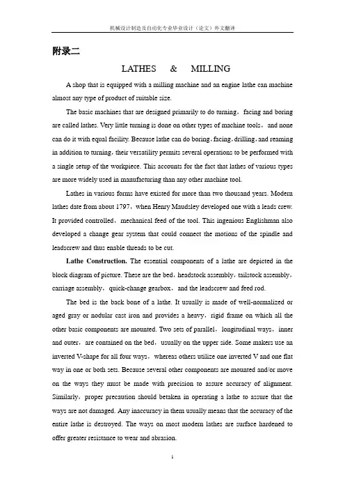
机械设计制造及自动化专业毕业设计(论文)外文翻译附录二LATHES & MILLINGA shop that is equipped with a milling machine and an engine lathe can machine almost any type of product of suitable size.The basic machines that are designed primarily to do turning,facing and boring are called lathes. Very little turning is done on other types of machine tools,and none can do it with equal facility. Because lathe can do boring,facing,drilling,and reaming in addition to turning,their versatility permits several operations to be performed with a single setup of the workpiece. This accounts for the fact that lathes of various types are more widely used in manufacturing than any other machine tool.Lathes in various forms have existed for more than two thousand years. Modern lathes date from about 1797,when Henry Maudsley developed one with a leads crew. It provided controlled,mechanical feed of the tool. This ingenious Englishman also developed a change gear system that could connect the motions of the spindle and leadscrew and thus enable threads to be cut.Lathe Construction.The essential components of a lathe are depicted in the block diagram of picture. These are the bed,headstock assembly,tailstock assembly,carriage assembly,quick-change gearbox,and the leadscrew and feed rod.The bed is the back bone of a lathe. It usually is made of well-normalized or aged gray or nodular cast iron and provides a heavy,rigid frame on which all the other basic components are mounted. Two sets of parallel,longitudinal ways,inner and outer,are contained on the bed,usually on the upper side. Some makers use an inverted V-shape for all four ways,whereas others utilize one inverted V and one flat way in one or both sets. Because several other components are mounted and/or move on the ways they must be made with precision to assure accuracy of alignment. Similarly,proper precaution should betaken in operating a lathe to assure that the ways are not damaged. Any inaccuracy in them usually means that the accuracy of the entire lathe is destroyed. The ways on most modern lathes are surface hardened to offer greater resistance to wear and abrasion.The headstock is mounted in a fixed position on the inner ways at one end of the lathe bed. It provides a powered means of rotating the work at various speeds. It consists,essentially,of a hollow spindle,mounted in accurate bearings,and a set of transmission gears——similar to a truck transmission——through which the spindle can be rotated at a number of speeds. Most lathes provide from eight to eighteen speeds,usually in a geometric ratio,and on modern lathes all the speeds can be obtained merely by moving from two to four levers. An increasing trend is to provide a continuously variable speed range through electrical or mechanical drives.Because the accuracy of a lathe is greatly dependent on the spindle,it is of heavy construction and mounted in heavy bearings,usually preloaded tapered roller or ball types. Along- itudinal hole extends through the spindle so that long bar stock can be fed through it. The size of this hole is an important size dimension of a lathe because it determines the maximum size of bar stock that can be machined when the material must be fed through the spindle.The inner end of the spindle protrudes from the gear box and contains a means for mounting various types of chucks,face plates,and dog plates on it. Whereas small lathes often employ a threaded section to which the chucks are screwed,most large lathes utilize either cam-lock or key-drive taper noses. These provide a large-diameter taper that assures the accurate alignment of the chuck,and a mechanism that permits the chuck or face plate to be locked or unlocked in position without the necessity of having to rotate these heavy attachments.Power is supplied to the spindle by means of an electric motor through a V-belt or silent-chain drive. Most modern lathes have motors of from 5 to15 horsepower to provide adequate power for carbide and ceramic tools at their high cutting speeds.The tailstock assembly consists,essentially,of three parts. A lower casting fits on the inner ways of the bed and can slide longitudinally thereon,with a means for clamping the entire assembly in any desired location. An upper casting fits on the lower one and can be moved transversely upon it on some type of keyed ways. This transverse motion permits aligning the tailstock and headstock spindles and provides amethod of turning tapers. The third major component of the assembly is the tailstock quill. This is a hollow steel cylinder,usually about2 to3 inches in diameter,that can be moved several inches longitudinally in and out of the upper casting by means of a hand wheel and screw. The open end of the quill hole terminates in a Morse taper in which a lathe center,or various tools such as drills,can be held. A graduated scale,several inches in length,usually is engraved on the outside of the quill to aid in controlling its motion in and out of the upper casting. A locking device permits clamping the quill in any desired position.The carriage assembly provides the means for mounting and moving cutting tools. The carriage is a relatively flat H-shaped casting that rests and moves on the outer set of ways on the bed. The transverse bar of the carriage contains ways on which the cross slide is mounted and can be moved by means of a feed screw that is controlled by a small hand wheel and a graduated dial. Through the cross slide a means is provided for moving the lathe tool in the direction normal to the axis of rotation of the work.On most lathes the tool post actually is mounted on a compound rest. This consists of abase,which is mounted on the cross slide so that it can be pivoted about a vertical axis,and an upper casting. The upper casting is mounted on ways on this base so that it can be moved back and forth and controlled by means of a short lead screw operated by a hand wheel and a calibrated dial.Manual and powered motion for the carriage,and powered motion for the cross slide,is provided by mechanisms within the apron,attached to the front of the carriage. Manual movement of the carriage along the bed is effected by turning a hand wheel on the front of the apron,which is geared to a pinion on the back side. This pinion engages a rack that is attached beneath the upper front edge of the bed in an inverted position.To impart powered movement to the carriage and cross slide,a rotating feed rod is provided. The feed rod,which contains a keyway through out most of its length,passes through the two reversing bevel pinions and is keyed to them . Either pinion cam be brought into mesh with amating bevel gear by means of the reversing lever on the front of the apron and thus provide “forward” or “reverse” power to the carriage. Suitable clutches connect either the rack pinion orthe cross-slide screw to provide longitudinal motion of the carriage or transverse motion of cross slide.For cutting threads,a second means of longitudinal drive is provided by a lead screw. Whereas motion of the carriage when driven by the feed-rod mechanism takes place through a friction clutch in which slippage is possible,motion through the lead screw is by a direct,mechanical connection between the apron and the lead screw. This is achieved by a split nut. By means of a clamping lever on the front of the apron,the split nut can be closed around the lead screw. With the split nut closed,the carriage is moved along the lead screw by direct drive without possibility of slippage.Modern lathes have a quick-change gear box. The input end of this gearbox is driven from the lathe spindle by means of suitable gearing. The out put end of the gear box is connected to the feed rod and lead screw. Thus,through this gear train,leading from the spindle to the quick-change gearbox,thence to the lead screw and feed rod,and then to the carriage,the cutting tool can be made to move a specific distance,either longitudinally or transversely,for each revolution of the spindle. A typical lathe provides,through the feed rod,forty-eight feeds ranging from 0.002 inch to0.118 inch per revolution of the spindle,and,through the lead screw,leads for cutting forty-eight different threads from 1.5 to 92perinch.On some older and some cheaper lathes,one or two gears in the gear train between the spindle and the change gear box must be changed in order to obtain a full range of threads and feeds.Milling is a basic machining process in which the surface is generated by the progressive formation and removal of chips of material from the workpiece as it is fed to a rotating cutter in a direction perpendicular to the axis of the cutter. .In some cases the workpiece is stationary and the cutter is fed to the work. In most instances a multiple-tooth cutter is used so that the metal removal rate is high,and frequently the desired surface is obtained in a single pass of the work.The tool used in milling is known as a milling cutter. It usually consists of acylindrical body which rotates on its axis and contains equally spaced peripheral teeth that intermittently engage and cut the workpiece. In some cases the teeth extend part way across one or both ends of the cylinder.Because the milling principle provides rapid metal removal and can produce good surface finish,it is particularly well-suited for mass-production work,and excellent milling machines have been developed for this purpose. However,very accurate and versatile milling machines of a general-purpose nature also have been developed that are widely used in job-shop and tool and die work. A shop that is equipped with a milling machine and an engine lathe can machine almost any type of product of suitable size.Types of Milling Operations. Milling operations can be classified into two broad categories,each of which has several variations:1.In peripheral milling a surface is generated by teeth located in the periphery of the cutter body;the surface is parallel with the axis of rotation of the cutter. Both flat and formed surfaces can be produced by this method. The cross section of the resulting surface corresponds to the axial contour of the cutter. This procedure often is called slab milling.1.In face milling the generated flat surface is at right angles to the cutteraxis and is thecombined result of the actions of the portions of the teeth located on both the periphery and thewith the face portions providing a finishing action.The basic concepts of peripheral and face milling are illustrated in Fig. Peripheral milling operations usually are performed on machines having horizontal spindles,whereas face milling is done on both horizontal-and vertical-spindle machines.Surface Generation in Milling. Surfaces can be generated in milling by two distinctly different methods depicted in Fig. Note that in up milling the cutter rotates against the direction of feed the workpiece,whereas in down milling the rotation is in the same direction as the feed .As shown in Fig., the method of chip formation is quitedifferent in the two cases. In up milling the c hip is very thin at the beginning, where the tooth first contacts the work,and increases in thickness, be-coming a maximum where the tooth leaves the work. The cutter tends to push the work along and lift it upward from the table. This action tends to eliminate any effect of looseness in the feed screw and nut of the milling machine table and results in a smooth cut. However, the action also tends to loosen the work from the clamping device so that greater clamping forcers must be employed. In addition, the smoothness of the generated surface depends greatly on the sharpness of the cutting edges.In down milling,maximum chip thickness occurs close to the point at which the tooth contacts the work. Because the relative motion tends to pull the workpiece into the cutter,all possibility of looseness in the table feed screw must be eliminated if down milling is to be used. It should never be attempted on machines that are not designed for this type of milling. In as mush as the material yields in approximately a tangential direction at the end of the tooth engagement,there is much less tendency for the machined surface to show tooth marks than when up milling is used. Another consider able advantage of down milling is that the cutting force tends to hold the work against the machine table,permitting lower clamping force to be employed. This is particularly advantageous when milling thin workpiece or when taking heavy cuts.Sometimes a disadvantage of down milling is that the cutter teeth strike against the surface of the work at the beginning of each chip. When the workpiece has a hard surface,such as castings do,this may cause the teeth to dull rapidly.Milling Cutters. Milling cutters can be classified several ways. One method is to group them into two broad classes,based on tooth relief,as follows:1. Profile-cutters have relief provided on each tooth by grinding a small land back of the cutting edge. The cutting edge may be straight or curved.2.In form or cam-relieved cutters the cross section of each tooth is an eccentric curve behind the cutting edge,thus providing relief. All sections of the eccentric relief,parallel with the cutting edge,must have the same contour as the cutting edge. Cutters of this type are sharpened by grinding only the face of the teeth,with the contour of the cutting edge thus remaining unchanged.Another useful method of classification is according to the method of mounting the cutter. Arbor cutters are those that have a center hole so they can be mounted on an arbor. Shank cutters have either tapered or straight integral shank. Those with tapered shanks can be mounted directly in the milling machine spindle,whereas straight-shank cutters are held in a chuck. Facing cuttersusually are bolted to the end of a stub arbor.Types of Milling Cutters. Plain milling cutters are cylindrical or disk-shaped,having straight or helical teeth on the periphery. They are used for milling flat surfaces. This type of operation is called plain or slab milling. Each tooth in a helical cutter engages the work gradually,and usually more than one tooth cuts at a given time. This reduces shock and chattering tendencies and promotes a smoother surface. Consequently,this type of cutter usually is preferred over one with straight teeth. Side milling cutters are similar to plain milling cutters except that the teeth extend radially part way across one or both ends of the cylinder toward the center. The teeth may be either straight or helical. Frequently these cutters are relatively narrow,being disklike in shape. Two or more side milling cutters often are spaced on an arbor to make simultaneous,parallel cuts,in an operation called straddle milling.Interlocking slotting cutters consist of two cutters similar to side mills,but made to operate as a unit for milling slots. The two cutters are adjusted to the desired width by inserting shims between them.Staggered-tooth milling cutters are narrow cylindrical cutters having staggered teeth,and with alternate teeth having opposite helix angles. They are ground to cut only on the periphery,but each tooth also has chip clearance ground on the protruding side. These cutters have a free cutting action that makes them particularly effective in milling deep slots. Metal-slitting saws are thin,plain milling cutters,usually from 1/32 to 3/16 inch thick,which have their sides slightly“dished”to provide clearance and prevent binding. They usually have more teeth per inch of diameter than ordinary plain milling cutters and are used for milling deep,narrow slots and for cutting-off operations.附录2车床和铣床车间里拥有一台车床和一台普通铣床就能加工出具有适合尺寸的各种产品。
英文资料High-speed millingHigh-speed machining is an advanced manufacturing technology, different from the traditional processing methods. The spindle speed, cutting feed rate, cutting a small amount of units within the time of removal of material has increased three to six times. With high efficiency, high precision and high quality surface as the basic characteristics of the automobile industry, aerospace, mold manufacturing and instrumentation industry, such as access to a wide range of applications, has made significant economic benefits, is the contemporary importance of advanced manufacturing technology. For a long time, people die on the processing has been using a grinding or milling EDM (EDM) processing, grinding, polishing methods. Although the high hardness of the EDM machine parts, but the lower the productivity of its application is limited. With the development of high-speed processing technology, used to replace high-speed cutting, grinding and polishing process to die processing has become possible. To shorten the processing cycle, processing and reliable quality assurance, lower processing costs.1 One of the advantages of high-speed machiningHigh-speed machining as a die-efficient manufacturing, high-quality, low power consumption in an advanced manufacturing technology. In conventional machining in a series of problems has plagued by high-speed machining of the application have been resolved.1.1 Increase productivityHigh-speed cutting of the spindle speed, feed rate compared withtraditional machining, in the nature of the leap, the metal removal rate increased 30 percent to 40 percent, cutting force reduced by 30 percent, the cutting tool life increased by 70% . Hardened parts can be processed, a fixture in many parts to be completed rough, semi-finishing and fine, and all other processes, the complex can reach parts of the surface quality requirements, thus increasing the processing productivity and competitiveness of products in the market.1.2 Improve processing accuracy and surface qualityHigh-speed machines generally have high rigidity and precision, and other characteristics, processing, cutting the depth of small, fast and feed, cutting force low, the workpiece to reduce heat distortion, and high precision machining, surface roughness small. Milling will be no high-speed processing and milling marks the surface so that the parts greatly enhance the quality of the surface. Processing Aluminum when up Ra0.40.6um, pieces of steel processing at up to Ra0.2 ~ 0.4um.1.3 Cutting reduce the heatBecause the main axis milling machine high-speed rotation, cutting a shallow cutting, and feed very quickly, and the blade length of the workpiece contacts and contact time is very short, a decrease of blades and parts of the heat conduction. High-speed cutting by dry milling or oil cooked up absolute (mist) lubrication system, to avoid the traditional processing tool in contact with the workpiece and a lot of shortcomings to ensure that the tool is not high temperature under the conditions of work, extended tool life.1.4 This is conducive to processing thin-walled partsHigh-speed cutting of small cutting force, a higher degree of stability, Machinable with high-quality employees compared to the company may be very good, but other than the company's employees may Suanbu Le outstanding work performance. For our China practice, we use the models to determine the method of staff training needs are simple and effective. This study models can be an external object, it can also be a combination of internal and external. We must first clear strategy for the development of enterprises. Through the internal and external business environment and organizational resources, such as analysis, the future development of a clear business goals and operational priorities. According to the business development strategy can be compared to find the business models, through a comparative analysis of the finalization of business models. In determining business models, a, is the understanding of its development strategy, or its market share and market growth rate, or the staff of the situation, and so on, according to the companies to determine the actual situation. As enterprises in different period of development, its focus is different, which means that enterprises need to invest the manpower and financial resources the focus is different. So in a certain period of time, enterprises should accurately selected their business models compared with the departments and posts, so more practical significance, because the business models are not always good, but to compare some aspects did not have much practical significance, Furthermore This can more fully concentrate on the business use of limited resources. Identify business models, and then take the enterprise of the corresponding departments and staff with the business models for comparison, the two can be found in the performance gap, a comparative analysis to find reasons, in accordance with this business reality, the final identification of training needs. The cost of training is needed, if not through an effective way to determine whether companies need to train and the training of the way, but blind to training, such training is difficult to achieve the desired results. A comparison only difference between this model is simple and practical training.1.5 Can be part of some alternative technology, such as EDM, grinding high intensity and high hardness processingHigh-speed cutting a major feature of high-speed cutting machine has the hardness of HRC60 parts. With the use of coated carbide cutter mold processing, directly to the installation of ahardened tool steel processing forming, effectively avoid the installation of several parts of the fixture error and improve the parts of the geometric location accuracy. In the mold of traditional processing, heat treatment hardening of the workpiece required EDM, high-speed machining replace the traditional method of cutting the processing, manufacturing process possible to omit die in EDM, simplifying the processing technology and investment costs .High-speed milling in the precincts of CNC machine tools, or for processing centre, also in the installation of high-speed spindle on the general machine tools. The latter not only has the processing capacity of general machine tools, but also for high-speed milling, a decrease of investment in equipment, machine tools increased flexibility. Cutting high-speed processing can improve the efficiency, quality improvement, streamline processes, investment and machine tool investment and maintenance costs rise, but comprehensive, can significantly increase economic efficiency.2 High-speed millingHigh-speed milling the main technical high-speed cutting technology is cutting the development direction of one of it with CNC technology, microelectronic technology, new materials and new technology, such as technology development to a higher level. High-speed machine tools and high-speed tool to achieve high-speed cutting is the prerequisite and basic conditions, in high-speed machining in the performance of high-speed machine tool material of choice and there are strict requirements.2.1 High-speed milling machine in order to achieve high-speed machiningGeneral use of highly flexible high-speed CNC machine tools, machining centers, and some use a dedicated high-speed milling, drilling. At the same time a high-speed machine tool spindle system and high-speed feeding system, high stiffness of the main characteristics of high-precision targeting and high-precision interpolation functions, especially high-precision arc interpolation function. High-speed machining systems of the machine a higher demand, mainly in the following areas:General use of highly flexible high-speed CNC machine tools, machining centers, and some use a dedicated high-speed milling, drilling. At the same time a high-speed machine tool spindle system and high-speed feeding system, high stiffness of the main characteristics of high-precision targeting and high-precision interpolation functions, especially high-precision arc interpolation function. High-speed machining systems of the machine a higher demand, mainly in the following areas:High-speed milling machine must have a high-speed spindle, the spindle speed is generally 10000 ~ 100000 m / min, power greater than 15 kW. But also with rapid speed or in designated spots fast-stopping performance. The main axial space not more than 0 .0 0 0 2 m m. Often using high-speed spindle-hydrostatic bearings, air pressure-bearing, mixed ceramic bearings, magneticbearing structure of the form. Spindle cooling general use within the water or air cooled.High-speed processing machine-driven system should be able to provide 40 ~ 60 m / min of the feed rate, with good acceleration characteristics, can provide 0.4 m/s2 to 10 m/s2 acceleration and deceleration. In order to obtain good processing quality, high-speed cutting machines must have a high enough stiffness. Machine bed material used gray iron, can also add a high-damping base of concrete, to prevent cutting tool chatter affect the quality of processing. A high-speed data transfer rate, can automatically increase slowdown. Processing technology to improve the processing and cutting tool life. At present high-speed machine tool manufacturers, usually in the general machine tools on low speed, the feed of the rough and then proceed to heat treatment, the last in the high-speed machine on the half-finished and finished, in improving the accuracy and efficiency at the same time, as far as possible to reduce processing Cost.2.2 High-speed machining toolHigh-speed machining tool is the most active one of the important factors, it has a direct impact on the efficiency of processing, manufacturing costs and product processing and accuracy. Tool in high-speed processing to bear high temperature, high pressure, friction, shock and vibration, such as loading, its hardness and wear-resistance, strength and toughness, heat resistance, technology and economic performance of the basic high-speed processing performance is the key One of the factors. High-speed cutting tool technology development speed, the more applications such as diamond (PCD), cubic boron nitride (CBN), ceramic knives, carbide coating, (C) titanium nitride Carbide TIC (N) And so on. CBN has high hardness, abrasion resistance and the extremely good thermal conductivity, and iron group elements between the great inertia, in 1300 ℃ would not have happened significant role in the chemical, also has a good stability. The experiments show that with CBN cutting toolHRC35 ~ 67 hardness of hardened steel can achieve very high speed. Ceramics have good wear resistance and thermal chemical stability, its hardness, toughness below the CBN, can be used for processing hardness of HRC <5 0 parts. Carbide Tool good wear resistance, but the hardness than the low-CBN and ceramics. Coating technology used knives, cutting tools can improve hardness and cutting the rate, for cutting HRC40 ~ 50 in hardness between the workpiece. Can be used to heat-resistant alloys, titanium alloys, hightemperature alloy, cast iron, Chungang, aluminum and composite materials of high-speed cutting Cut, the most widely used. Precision machining non-ferrous metals or non-metallic materials, or the choice of polycrystalline diamond Gang-coated tool.2.3 High-speed processing technologyHigh-speed cutting technology for high-speed machining is the key. Cutting Methods misconduct, will increase wear tool to less than high-speed processing purposes. Only high-speed machine tool and not a good guide technology, high-speed machining equipment can not fullyplay its role. In high-speed machining, should be chosen with milling, when the milling cutter involvement with the workpiece chip thickness as the greatest, and then gradually decreased. High-speed machining suitable for shallow depth of cut, cutting depth of not more than 0.2 mm, to avoid the location of deviation tool to ensure that the geometric precision machining parts. Ensure that the workpiece on the cutting constant load, to get good processing quality. Cutting a single high-speed milling path-cutting mode, try not to interrupt the process and cutting tool path, reducing the involvement tool to cut the number to be relatively stable cutting process. Tool to reduce the rapid change to, in other words when the NC machine tools must cease immediately, or Jiangsu, and then implement the next step. As the machine tool acceleration restrictions, easy to cause a waste of time, and exigency stop or radical move would damage the surface accuracy. In the mold of high-speed finishing, in each Cut, cut to the workpiece, the feed should try to change the direction of a curve or arc adapter, avoid a straight line adapter to maintain the smooth process of cutting.3 Die in high-speed milling processing ofMilling as a highly efficient high-speed cutting of the new method,inMould Manufacturing has been widely used. Forging links in the regular production model, with EDM cavity to be 12 ~ 15 h, electrodes produced 2 h. Milling after the switch to high-speed, high-speed milling cutter on the hardness of HRC 6 0 hardened tool steel processing. The forging die processing only 3 h20min, improve work efficiency four to five times the processing surface roughness of Ra0.5 ~ 0.6m, fully in line with quality requirements.High-speed cutting technology is cutting technology one of the major developments, mainly used in automobile industry and die industry, particularly in the processing complex surface, the workpiece itself or knives rigid requirements of the higher processing areas, is a range of advanced processing technology The integration, high efficiency and high quality for the people respected. It not only involves high-speed processing technology, but also including high-speed processing machine tools, numerical control system, high-speed cutting tools and CAD / CAM technology. Die-processing technology has been developed in the mold of the manufacturing sector in general, and in my application and the application of the standards have yet to be improved, because of its traditional processing with unparalleled advantages, the future will continue to be an inevitable development of processing technology Direction.4 Numerical control technology and equipping development trend and countermeasureEquip the engineering level, level of determining the whole national economy of the modernized degree and modernized degree of industry, numerical control technology is it develop new developing new high-tech industry and most advanced industry to equip (such as information technology and his industry, biotechnology and his industry, aviation, spaceflight, etc. national defense industry) last technology and getting more basic most equipment. Marx has ever said "the differences of different economic times, do not lie in what is produced, and lie in how to produce,produce with some means of labor ". Manufacturing technology and equipping the most basic means of production that are that the mankind produced the activity, and numerical control technology is nowadays advanced manufacturing technology and equips the most central technology. Nowadays the manufacturing industry all around the world adopts numerical control technology extensively, in order to improve manufacturing capacity and level, improve the adaptive capacity and competitive power to the changeable market of the trends. In addition every industrially developed country in the world also classifies the technology and numerical control equipment of numerical control as the strategic materials of the country, not merely take the great measure to develop one's own numerical control technology and industry, and implement blockading and restrictive policy to our country in view of " high-grade, precision and advanced key technology of numerical control " and equipping. In a word, develop the advanced manufacturing technology taking numerical control technology as the core and already become every world developed country and accelerate economic development in a more cost-effective manner, important way to improve the overall national strength and national position. Numerical control technology is the technology controlled to mechanical movement and working course with digital information, integrated products of electromechanics that the numerical control equipment is the new technology represented by numerical control technology forms to the manufacture industry of the tradition and infiltration of the new developing manufacturing industry, namely the so-called digitization is equipped, its technological range covers a lot of fields: (1)Mechanical manufacturing technology; (2)Information processing, processing, transmission technology; (3)Automatic control technology; (4)Servo drive technology;(5)Technology of the sensor; (6)Software engineering ,etc..Development trend of a numerical control technologyThe application of numerical control technology has not only brought the revolutionary change to manufacturing industry of the tradition, make the manufacturing industry become the industrialized symbol , and with the constant development of numerical control technology and enlargement of the application, the development of some important trades (IT , automobile , light industry , medical treatment ,etc. ) to the national economy and the people's livelihood of his plays a more and more important role, because the digitization that these trades needed to equip has already been the main trend of modern development. Numerical control technology in the world at present and equipping the development trend to see, there is the following several respect [1- ] in its main research focus.5 A high-speed, high finish machining technology and new trend equippedThe efficiency, quality are subjavanufacturing technology. High-speed, high finish machining technology can raise the efficiency greatly , improve the quality and grade of the products, shorten production cycle and improve the market competitive power. Japan carries the technological research association first to classify it as one of the 5 great modern manufacturing technologies forthis, learn (CIRP) to confirm it as the centre in the 21st century and study one of the directions in international production engineering.In the field of car industry, produce one second when beat such as production of 300,000 / vehicle per year, and many variety process it is car that equip key problem that must be solved one of; In the fields of aviation and aerospace industry, spare parts of its processing are mostly the thin wall and thin muscle, rigidity is very bad, the material is aluminium or aluminium alloy, only in a situation that cut the speed and cut strength very small high, could process these muscles, walls. Adopt large-scale whole aluminium alloy method that blank " pay empty " make the wing recently, such large-scale parts as the fuselage ,etc. come to substitute a lot of parts to assemble through numerous rivet , screw and other connection way, make the intensity , rigidity and dependability of the component improved. All these, to processing and equipping the demand which has proposed high-speed, high precise and high flexibility.According to EMO2001 exhibition situation, high-speed machining center is it give speed can reach 80m/min is even high , air transport competent speed can up to 100m/min to be about to enter. A lot of automobile factories in the world at present, including Shanghai General Motors Corporation of our country, have already adopted and substituted and made the lathe up with the production line part that the high-speed machining center makes up. HyperMach lathe of U.S.A. CINCINNATI Company enters to nearly biggest 60m/min of speed, it is 100m/min to be fast, the acceleration reaches 2g, the rotational speed of the main shaft has already reached 60 000r/min. Processing a thin wall of plane parts, spend 30min only, and same part general at a high speed milling machine process and take 3h, the ordinary milling machine is being processed to need 8h; The speed and acceleration of main shaft of dual main shaft lathes of Germany DMG Company are up to 120000r/mm and 1g.In machining accuracy, the past 10 years, ordinary progression accuse of machining accuracy of lathe bring 5μm up to from 10μm already, accurate grades of machining center from 3~5μm, rise to 1~1.5μm, and ultraprecision machining accuracy is i t enter nanometer grade to begin already (0.01μm).In dependability, MTBF value of the foreign numerical control device has already reached above 6 000h, MTBF value of the servo system reaches above 30000h, demonstrate very high dependability .In order to realize high-speed, high finish machining, if the part of function related to it is electric main shaft, straight line electrical machinery get fast development, the application is expanded further .5.2 Link and process and compound to process the fast development of the lathe in 5 axesAdopt 5 axles to link the processing of the three-dimensional curved surface part, can cut with the best geometry form of the cutter , not only highly polished, but also efficiency improves by a large margin . It is generally acknowledged, the efficiency of an 5 axle gear beds can equal 2 3 axle gearbeds, is it wait for to use the cubic nitrogen boron the milling cutter of ultra hard material is milled and pared at a high speed while quenching the hard steel part, 5 axles link and process 3 constant axles to link and process and give play to higher benefit. Because such reasons as complicated that 5 axles link the numerical control system , host computer structure that but go over, it is several times higher that its price links the numerical control lathe than 3 axles , in addition the technological degree of difficulty of programming is relatively great, have restricted the development of 5 axle gear beds.At present because of electric appearance of main shaft, is it realize 5 axle complex main shaft hair structure processed to link greatly simplify to make, it makes degree of difficulty and reducing by a large margin of the cost, the price disparity of the numerical control system shrinks. So promoted 5 axle gear beds of head of complex main shaft and compound to process the development of the lathe (process the lathe including 5).At EMO2001 exhibition, new Japanese 5 of worker machine process lathe adopt complex main shaft hair, can realize the processing of 4 vertical planes and processing of the wanton angle, make 5 times process and 5 axles are processed and can be realized on the same lathe, can also realize the inclined plane and pour the processing of the hole of awls. Germany DMG Company exhibits the DMUVoution series machining center, but put and insert and put processing and 5 axles 5 times to link and process in once, can be controlled by CNC system or CAD/CAM is controlled directly or indirectly.5.3 Become the main trend of systematic development of contemporary numerical control intelligently, openly, networkedly.The numerical control equipment in the 21st century will be sure the intelligent system, the intelligent content includes all respects in the numerical control system: It is intelligent in order to pursue the efficiency of processing and process quality, control such as the self-adaptation of the processing course, the craft parameter is produced automatically; Join the convenient one in order to improve the performance of urging and use intelligently, if feedforward control , adaptive operation , electrical machinery of parameter , discern load select models , since exactly makes etc. automatically; The ones that simplified programming , simplified operating aspect are intelligent, for instance intelligent automatic programming , intelligent man-machine interface ,etc.; There are content of intelligence diagnose , intelligent monitoring , diagnosis convenient to be systematic and maintaining ,etc..Produce the existing problem for the industrialization of solving the traditional numerical control system sealing and numerical control application software. A lot of countries carry on research to the open numerical control system at present, such as NGC of U.S.A. (The Next Generation Work-Station/Machine Control), OSACA of European Community (Open System Architecture for Control within Automation Systems), OSEC (Open System Environment for Controller) of Japan, ONC (Open Numerical Control System) of China, etc.. The numerical control system melts tobecome the future way of the numerical control system open. The so-called open numerical control system is the development of the numerical control system can be on unified operation platform, face the lathe producer and end user, through changing, increasing or cutting out the structure target(numerical control function), form the serration, and can use users specially conveniently and the technical know-how is integrated in the control system, realize the open numerical control system of different variety , different grade fast, form leading brand products with distinct distinction. System structure norm of the open numerical control system at present, communication norm , disposing norm , operation platform , numerical control systematic function storehouse and numerical control systematic function software development ,etc. are the core of present research.The networked numerical control equipment is a new light spot of the fair of the internationally famous lathe in the past two years. Meeting production line , manufacture system , demand for the information integration of manufacturing company networkedly greatly of numerical control equipment, realize new manufacture mode such as quick make , fictitious enterprise , basic Entrance that the whole world make too. Some domestic and international famous numerical control lathes and systematic manufacturing companies of numerical control have all introduced relevant new concepts and protons of a machine in the past two years, if in EMO2001 exhibition, " Cyber Production Center " that the company exhibits of mountain rugged campstool gram in Japan (Mazak) (intellectual central production control unit, abbreviated as CPC); The lathe company of Japanese big Wei (Okuma ) exhibits " IT plaza " (the information technology square , is abbreviated as IT square ); Open Manufacturing Environment that the company exhibits of German Siemens (Siemens ) (open the manufacturing environment, abbreviated as OME),etc., have reflected numerical control machine tooling to the development trend of networked direction.5.4 Pay attention to the new technical standard, normal setting-up5.4.1 Design the norm of developing about the numerical control systemAs noted previously, there are better common ability, flexibility, adaptability, expanding in the open numerical control system, such countries as U.S.A. ,European Community and Japan ,etc. implement the strategic development plan one after another , carry on the research and formulation of the systematic norm (OMAC , OSACA , OSEC ) of numerical control of the open system structure, 3 biggest economies in the world have carried on the formulation that nearly the same science planned and standardized in a short time, have indicated a new arrival of period of change of numerical control technology. Our country started the research and formulation of standardizing the frame of ONC numerical control system of China too in 2000.5.4.2 About the numerical control standardThe numerical control standard is a kind of trend of information-based development of manufacturing industry. Information exchange among 50 years after numerical control technology was born was all because of ISO6983 standard, namely adopt G, M code describes how processes,。
毕业论文附件材料目录1 英文文献翻译 (1)1.1 Shift gearbox (1)1.2 变速箱的换挡方式 (12)1 英文文献翻译1.1 Shift gearboxClassification usually gearbox as follows:Manual transmissionThe general automatic gearbox / mon automatic transmission with tiptronicCVT stepless gearbox with gear box of the /CVTDual clutch gearboxSequential gearbox(1) manual gearboxManual transmission, also known as manual gear, English name is manual transmission, referred to as MT, which push the shift lever to change gears meshing position inside the transmission, changing the transmission ratio, so as to achieve the purpose of speed. Step on the clutch, can move the shift lever.The working principle of a manual gearboxThe manual gear box is posed of different gear ratio of the gear group, its basic principle is through the gear group work in different, to realize the transformation of gear ratio. As the key link for power distribution, transmission must have the power input shaft and the output shaft of the big two, together constitute the transmission gear, is a manual transmission is the most basic ponent. The power input is connected with the clutch shaft clutch transmission, from the power to directly through the input shaft to the group, the gear set is posed of different diameter gear, gear power transmission effectof different proportion reached is pletely different, the usual shift driving also refers to change gear ratio.Next, let us through a simple model to tell you, the principle of manual gearbox shift. Below is a simple structural model of 3 axis 2 speed gearbox.The input shaft (green) is also called the first shaft, connected by a clutch and engine, shaft and the gear is a hard connected ponents. Red is called the intermediate gear shaft. Enter the two gear shaft and intermediate shaft is in constant mesh state, so when the input shaft rotates will drive shaft rotation. Yellow is the output shaft, it is also called the second shafts and connected to the drive shaft (only for rear wheel drive, the precursor is generally two), and then through the differential drive vehicles.When the wheel rotates the same with spline shaft to rotate together, at this time,blue gear shaft can occur on the spline shaft relative free rotation. Therefore, the engine stops, and the wheel is rotated, the blue gear and shaft in the stationary state, and the spline shaft with wheels. The principle and the rear axle of the bicycle flywheel is similar. Blue gear and spline shaft is posed of a sleeve to connect, sleeve with spline shaft to rotate, but also can be free to slide on the spline shaft to gear.With these, the shifting process is very good understanding, when connecting sleeve and a blue gear, engine power will be transmitted to the output shaft through the shaft, at the same time, blue gear left in free rotation, but because there is no and sleeve engaged, so it does not affect the spline shaft. If the sleeve between the two blue gear, the gearbox in neutral position, the two blue gear on the spline shaft rotate freely, without mutual interference.Principle of a conventional 5 speed manual gearbox shift is the same, only thegearbox structure increased the number of sleeve and the gear sets, so that it has more gear. But the reverse is based on the intermediate shaft (red) and the output shaft (blue) is added between a gear to achieve. Due to the increase of a gear, the reverse gear will always rotate toward other gear in the opposite direction. The gear because only to change gear rotation direction function, so it is also called the idler.5 block two shaft transmission structure, the input shaft and the driving gear are integrated into a whole, simplifies the structure and saves spaceIn addition to the traditional three axis manual gearbox, the widespread use of cars is two axis manual transmission, its structure and the three shaft of the gearbox is similar, only the input shaft and intermediate shaft as a shaft, therefore has the advantages of simple structure, small size advantages, in addition, it also has the middle gear transmission high efficiency, and low noise characteristics, so it is more suitable to be theprecursor home car general car transmission form, is currently the most widely used, its shortings is not set up direct gear, transmission and file than the design cannot be too high. While driving, three shaft gearbox used is still the traditional.Manual gearbox in general, is through the push rod is connected or cable to control the shift. Push rod shift control connection, more direct but vibration will be large; and the cable type although no vibration, but the shift is not very clear, it is each to have good and bad. In addition to shift the two pure mechanical control, in addition, and the use of electronic shift device of manual transmission, which can bine the merits of push and pull the shift between the good. This kind of gear box in the shift when the gear shift lever, shifting to the corresponding gear, the transmission will be motor drive the corresponding fork control sleeve and the gear is engaged, so that there is no gear is not clear, but the shift schedule can be controlled in the ideal range.So, a good manual transmission need to have what characteristic? The first transmission must have good gear handle, each gear position clear, have reasonable horizontal and vertical stroke, into the block resistance is small and with suction. What is more important is, the gear tooth between than arrangement must be reasonable. Because each gear position than distribution, directly affect the cohesion power vehicles moving in a smooth, usually require a low gear can effectively accelerate, high block to achieve high speed and efficient, and the distance between each block should be uniform, otherwise will be very easy to cause the channeling shift when the car.Analysis of the advantages and disadvantages of manual gearboxAdvantages Obviously, which is simple in structure, reliable performance,manufacturing and maintenance cost is low, and the transmission efficiency is high (theory will be more fuel-efficient), also, because it is pure mechanical control, shift reaction is fast, and can be more direct expression of driver's intention, and therefore more driving pleasure, these are the advantages of manual gearbox. But pared to automatic transmission, its operation is plicated, and frustration in gear switch when the obvious disadvantage is irreparable.(2) automatic gearboxAutomatic transmission AT, the full name of Auto Transmission, which is posed of hydraulic torque converter, posed of planetary gear and hydraulic control system, through the hydraulic transmission and gear bination to achieve variable speed moment.pared with the manual transmission, automatic transmission is very different in structure and usage. The manual is mainly regulated by different gear bination to change gear, and the automatic transmission is through the hydraulic transmission and gear bination to achieve the purpose of changing speed. Hydraulic torque converter is one of the most characteristic of the automatic gearbox parts, which is posed of a pump, turbine and guide wheel and other ponents, pump wheel and turbine is a bination of work, through the liquid pump wheel drives the turbine to rotate, and the wheel between the pump and turbine wheel through the reaction between the pump wheel and turbine implementation the speed difference and implementation of variable torque function, the driver, you only need to different intensity slam the pedal, the gearbox can automatically stop lifting. Since the torque converter automatic transmission torque range is not big enough, so in a later series several rows of planetary gear to improve efficiency, thehydraulic control system will change with the engine to manipulate the planetary gear, so as to realize the automatic transmission torque. In order to meet a variety of running process needs (such as parking, reversing), automatic transmission also has some manual shift lever position, like the P block (R block (anchor), after the block), block N (neutral), D (forward), block.From the performance that the more gear automatic gearbox, the car in the process of running more smoothly, acceleration is better, and more fuel-efficient. In addition to providing a fortable driving feeling, automatic transmission also has insurmountable defects. Dynamic automatic transmission response is not directly, which makes it in the "driving pleasure" slightly shortage. In addition, because of the use of hydraulic transmission, the automatic transmission gearbox transmission power loss.Tiptronic automatic transmissionHands appeared gearbox is in order to improve the automatic gearbox and operating economy and increase the setting, let the original puter automatic shift time back into the hands of drivers. At the same time, if in the city traffic in, or you can always switch back to automatic.A tiptronic automatic transmission is actually automatic gearbox, first appeared in a Porsche 911, manual gearbox electronic control system through the simulation of the operation of a manual gearbox. It appears, giving the driver a greater degree of freedom in the operation, can block up the blocking or shift paddles on the steering wheel to choose their own gear and shift the timing right, thereby greatly improving the driving pleasure.(3) CTV non-polar transmissionCVT (Continuously Variable Transmission), direct translation is a continuously variable transmission, which is continuously variable transmission. We often say, just as its name implies is that there is no clear and specific file, which operate on similar automatic gearbox, gear jump process but the ratio change is different from the automatic gearbox, but a continuous, so the power transmission continues smooth.CVT transmission system, the traditional gear by a pair of pulleys and a steel belt is replaced, each block is V structure is posed of two intervertebral disk, engine shaft is connected through a small pulley, steel belt drive pulley. Mystery lies in this special pulley: drive pulley structures CVT strange activity, divided into halves, can be close to or separate relative. Cone disc can tighten or open the thrust hydraulic, extrusion sheet steel chain so as to adjust the V slot width. When the cone disc inside mobile tightened, steel chain in the extrusion cones to center outside of the direction of movement (centrifugal direction), but moving to the center of the circle. In this way, steel chain drives the disc diameter increases, the transmission ratio is changed.The CVT gearbox what are the advantages?1, because there is no general automatic transmission gear, there will be no shift process of automatic transmission, shift the resulting sense of frustration will disappear, so the power output of CVT gearbox is linear, in actual driving very smooth.Theory of transmission system of 2 CVT, the gear can be an unlimited number of gear set, more freedom, the traditional transmission gear ratio, speed ratio and performance, fuel consumption, exhaust emissions balance, are more likely to achieve.3, the mechanical efficiency of CVT transmission, the province is oily considerably better than the automatic transmission mon, after manual gearbox, fuel economy is much better than.Since there are so many advantages, why not let all the cars using CVT gearbox? There are two factors:1, pared with the traditional automatic transmission, its cost is high; and the operation is undeserved word, the higher probability.2, CVT gearbox itself still has its shortings, is the transmission of the steel belt can withstand strength is limited, generally more than 2.8L capacity or power above 280N • M is its limit, but we also see that there are more and more cars such as Audi, or Nissan, has broken the limit, believe strip the problem will be solved gradually.(4) dual clutch gearboxDual clutch gearbox DCT, English name is Dual Clutch Transmission, because it has two clutches, so called "dual clutch transmission".Technology introducedDual clutch gearbox bines the advantages of manual transmission and automatic transmission, no torque converter, instead of using two sets of clutch, through two sets of clutch alternately work, to achieve seamless shift effect. Two clutches respectively control the odd block and even block, that is to say, in the shift before, DSG had the next gear meshing, after shifting instruction, DSG quickly sends instructions to the engine, the engine speed increases, the previous meshing gears quickly, while the first group of clutch fully liberalized, the pletion of a rise to block the action time, action andso on.Because without the torque converter, so the power of the engine can be fully played out, while the two clutch alternately work, shift time making, dynamic fault engine may be very limited. As the driver is the feeling that we are the most direct, switch gear action very quickly and smoothly, dynamic transmission process of almost uninterrupted, vehicle dynamic performance can be fully play. pared with the traditional automatic transmission with torque converter, the DSG shift more directly, the power loss is smaller, so the fuel consumption can be reduced by more than 10%.DeficienciesHowever, with the traditional automatic transmission ratio, DSG also has some inherent disadvantages, firstly it is because there is no use hydraulic torque converter, nor realize manual transmission "linkage" action, so for the small-displacement engine, low speed torque characteristic is not enough to be pletely exposed; secondly, because the DSG transmission using puter control, belonging to an intelligent transmission, it needs to send electronic signals to the engine block in the process of falling in the L /, the engine after reply, and the engine to be pleted with L / reduction gear. A large number of electronic ponents, but also increases the probability of its failure.The dual clutch mon with Volkswagen's DSG, Ford Powershift, Mitsubishi SST and Porsche PDK.(5) sequential gearboxSequential gearbox (AMT) is improved on the traditional manual gear transmission based on; it bines hydromechatronics automatic transmission has the advantages of bothAT and MT; AMT has the advantages of automatic transmission mon automatic transmission, and the retention efficiency of the original manual transmission gear transmission, the high cost of low, simple structure, easy manufacture. It is the reform in the present manual transmission, retained most of the original assembly, only to change the shift lever manual operating system part, the production of succession, to transform the input costs less, is very easy to be manufacturers to accept.The driver through the accelerator pedal and joystick to the electronic control unit (ECU) control signal transmission; electronic control unit collects the engine speed sensor, the speed sensor signal, the time to master the running state of the vehicle; electronic control unit (ECU) based on the best program according to these signals stored therein, optimal shifting rules, clutch fuzzy control rules engine oil, adaptive control law, action and temporal separation of the engine, clutch and transmission shift binding, the three to achieve the best matching. In order to obtain the excellent fuel economy and power performance and ability to smooth start and rapid shift, in order to achieve the desired results.But the AMT transmission is not perfect, the biggest disadvantage of AMT gearbox is shifting fort is poor, and generate power interruption in the process of shifting, the shift in the process of speed performance is not good.AMT mechanical gearbox, its basic structure and conventional manual gearbox consistent, generally only one input shaft and an output shaft (RWD usually a middle shaft), which generally is the input shaft 5 forward gear and output shaft gear is in constant mesh state, wherein the output shaft of the 1 gear and a reverse gear, 2 blockand the 3 block, 4 block and 5 block were shared by the three shift fork. The mechanism of two adjacent gear with a shifting mechanism, when the shift action, fork need once upon a gear defect, through neutral to the next gear gear meshing, due to three actions is the order, even if each action will be the time to a minimum, is still very difficult to obtain the shift speed fast enough."Independent innovation shift fork"The ISR gearbox has a unique structure, the gear arrangement it is different with the traditional AMT gearbox, also different from the dual clutch gearbox. The use of four independent shift fork, two stalls adjacent to the gear shift fork is posed of different control. Four independent fork respectively control 1 gear and reverse gear; block 3 and block 5, block 2 and block 4, block 6 and block 7, that is to say, from 1 until 6 block, two adjacent stalls are posed of two independent fork to respectively control.Because of this design, the shifting process can be further shortened: when two adjacent gear to gear switch, a shift fork and the current gear gear detachment, another gear meshing has already started, and a shift fork action and activates the electronic clutch three, because the action is almost synchronously, so that the whole time shorten. Lamborghini is pared originally claimed, performance is very good before the generation of the E-gear sequential gearbox, shift speed upgrade 40%, shift speed of 50 milliseconds is close to F1 gearbox level.Gear shift mechanism of ISR is driven by the electric hydraulic pump, a maximum of 60 bar pressure ensures the necessary operating speed, 7 hydraulic valve controls the gear shift mechanism of action, and the electric pump to provide power, double plateclutch tough also driven by hydraulic pressure, will be responsible for the torque of the 690Nm transmitted to the four wheels. Synchronizer gear ring is made from carbon fiber, not only wear but also reduce the overall quality of the gearbox.In the design process, the transmission is not only fast, shift quality is equally important, VOCIS design control procedure is also fully take into account the daily driving fort. The gearbox can choose three kinds of work modes: Strada (Road) or full automatic mode can provide fortable for shift operation oriented; Sport (motion) mode will postpone shifting node and provides a more rapid gear switch; Corsa (track) model can provide the best track shift strategy, the model can also provide the starting control, also is the ejection start function.1.2 变速箱的换挡方式通常变速箱的分类为以下几种:手动变速箱普通自动变速箱/普通自动变速箱带手自一体CVT无级变速箱/CVT带挡位的变速箱双离合变速箱序列变速箱(1) 手动变速箱手动变速器,也称手动挡,英文全称为manual transmission,简称MT,即用手拨动变速杆才能改变变速器内的齿轮啮合位置,改变传动比,从而到达变速的目的。
Optimization of fixture design with consideration of thermal deformation inface milling考虑端铣中热变形的最佳化夹具设计Huang, YingAbstract摘要Effective methods of fixture design are proposed to reduce machining error caused by cutting heat in face milling. Experiments show that thermal effect is critical to final error in the finish cut and that it dominates cutting accuracy. Therefore, a mathematical model is structured of the cutting heat source on behalf of the cutting tool, and the flatness error generation process in face finishing is demonstrated by computational simulation based on the moving cutting heat source model with FEW Concerning surface flatness due to the moving cutting heat source for relatively thin plate-shaped workpieces, different methodologies have been proposed to reduce flatness error, namely, the application of additional supports and optimization of the fixturing support layout. Cutting experiments and computational analyses show the effectiveness of the additional supports and the optimization methodology applied on the fixture design in view of flatness error due to cutting heat. The proposed methodologies are applicable and beneficial to improve cutting accuracy not only of plate-shaped workpieces but also of other geometry workpieces.用于减小端铣中因切削热而引起的加工误差的有效的夹具设计方法已经被提出。

中北大学信息商务学院本科毕业设计英文参考资料题目 Lathes系名专业姓名学号指导教师2016年6 月2 日译文标题车床简介原文标题Lathes作者(Serope kalpakjian)译名卡尔帕基安国籍美国原文出处/原文:LathesLathes are machine tools designed primarily to do turning, facing and boring, Very little turning is done on other types of machine tools, and none can do it with equal facility. Because lathes also can do drilling and reaming, their versatility permits several operations to be done with a single setup of the work piece. Consequently, more lathes of various types are used in manufacturing than any other machine tool.The essential components of a lathe are the bed, headstock assembly, tailstock assembly, and the leads crew and feed rod.The bed is the backbone of a lathe. It usually is made of well normalized or aged gray or nodular cast iron and provides s heavy, rigid frame on which all the other basic components are mounted. Two sets of parallel, longitudinal ways, inner and outer, are contained on the bed, usually on the upper side. Some makers use an inverted V-shape for all four ways, whereas others utilize one inverted V and one flat way in one or both sets, They are precision-machined to assure accuracy of alignment. On most modern lathes the way are surface-hardened to resist wear and abrasion, but precaution should be taken in operating a lathe to assure that the ways are not damaged. Any inaccuracy in them usually means that the accuracy of the entire lathe is destroyed.The headstock is mounted in a foxed position on the inner ways, usually at the left end of the bed. It provides a powered means of rotating the word at various speeds . Essentially, it consists of a hollow spindle, mounted in accurate bearings, and a set of transmission gears-similar to a truck transmission—through which the spindle can be rotated at a number of speeds. Most lathes provide from 8 to 18 speeds, usually in a geometric ratio, and on modern lathes all the speeds can be obtained merely by moving from two to four levers. An increasing trend is to provide a continuously variable speed range through electrical or mechanical drives.Because the accuracy of a lathe is greatly dependent on the spindle, it is of heavyconstruction and mounted in heavy bearings, usually preloaded tapered roller or ball types. The spindle has a hole extending through its length, through which long bar stock can be fed. The size of maximum size of bar stock that can be machined when the material must be fed through spindle.The tailsticd assembly consists, essentially, of three parts. A lower casting fits on the inner ways of the bed and can slide longitudinally thereon, with a means for clamping the entire assembly in any desired location, An upper casting fits on the lower one and can be moved transversely upon it, on some type of keyed ways, to permit aligning the assembly is the tailstock quill. This is a hollow steel cylinder, usually about 51 to 76mm(2to 3 inches) in diameter, that can be moved several inches longitudinally in and out of the upper casting by means of a hand wheel and screw.The size of a lathe is designated by two dimensions. The first is known as the swing. This is the maximum diameter of work that can be rotated on a lathe. It is approximately twice the distance between the line connecting the lathe centers and the nearest point on the ways, The second size dimension is the maximum distance between centers. The swing thus indicates the maximum work piece diameter that can be turned in the lathe, while the distance between centers indicates the maximum length of work piece that can be mounted between centers.Engine lathes are the type most frequently used in manufacturing. They areheavy-duty machine tools with all the components described previously and have power drive for all tool movements except on the compound rest. They commonly range in size from 305 to 610 mm(12 to 24 inches)swing and from 610 to 1219 mm(24 to 48 inches) center distances, but swings up to 1270 mm(50 inches) and center distances up to3658mm(12 feet) are not uncommon. Most have chip pans and a built-in coolant circulating system. Smaller engine lathes-with swings usually not over 330 mm (13 inches ) –also are available in bench type, designed for the bed to be mounted on a bench on a bench or cabinet.Although engine lathes are versatile and very useful, because of the time required for changing and setting tools and for making measurements on the work piece, thy are not suitable for quantity production. Often the actual chip-production tine is less than 30% of the total cycle time. In addition, a skilled machinist is required for all the operations, and such persons are costly and often in short supply. However, much of the operator’s time is consumed by simple, repetitious adjustments and in watching chips being made. Consequently, to reduce or eliminate the amount of skilled labor that is required, turret lathes, screw machines, and other types of semiautomatic and automatic lathes have been highly developed and are widely used in manufacturing.2 Numerical ControlOne of the most fundamental concepts in the area of advanced manufacturing technologies is numerical control (NC). Prior to the advent of NC, all machine tools ere manually operated and controlled. Among the many limitations associated with manual control machine tools, perhaps none is more prominent than the limitation of operator skills. With manual control, the quality of the product is directly related to and limited to the skills of the operator. Numerical control represents the first major step away from human control of machine tools.Numerical control means the control of machine tools and other manufacturing systems through the use of prerecorded, written symbolic instructions. Rather than operating a machine tool, an NC technician writes a program that issues operational instructions to the machine tool. For a machine tool to be numerically controlled, it must be interfaced with a device for accepting and decoding the programmed instructions, known as a reader.Numerical control was developed to overcome the limitation of human operators, and it has done so. Numerical control machines are more accurate than manually operated machines, they can produce parts more uniformly, they are faster, and the long-run tooling costs are lower. The development of NC led to the development of several other innovations in manufacturing technology:Electrical discharge machining,Laser cutting,Electron beam welding.Numerical control has also made machine tools more versatile than their manually operated predecessors. An NC machine tool can automatically produce a wide of parts, each involving an assortment of widely varied and complex machining processes. Numerical control has allowed manufacturers to undertake the production of products that would not have been feasible from an economic perspective using manually controlled machine tolls and processes.Like so many advanced technologies, NC was born in the laboratories of the Massachusetts Institute of Technology. The concept of NC was developed in the early 1950s with funding provided by the U.S. Air Force. In its earliest stages, NC machines were able to made straight cuts efficiently and effectively.However, curved paths were a problem because the machine tool had to be programmed to undertake a series of horizontal and vertical steps to produce a curve. The shorter the straight lines making up the steps, the smoother is the curve, Each line segment in the steps had to be calculated.This problem led to the development in 1959 of the Automatically Programmed Tools (APT) language. This is a special programming language for NC that uses statementssimilar to English language to define the part geometry, describe the cutting tool configuration, and specify the necessary motions. The development of the APT language was a major step forward in the fur ther development from those used today. The machines had hardwired logic circuits. The instructional programs were written on punched paper, which was later to be replaced by magnetic plastic tape. A tape reader was used to interpret the instructions written on the tape for the machine. Together, all of this represented a giant step forward in the control of machine tools. However, there were a number of problems with NC at this point in its development.A major problem was the fragility of the punched paper tape medium. It was common for the paper tape containing the programmed instructions to break or tear during a machining process. This problem was exacerbated by the fact that each successive time a part was produced on a machine tool, the paper tape carrying the programmed instructions had to be rerun through the reader. If it was necessary to produce 100 copies of a given part, it was also necessary to run the paper tape through the reader 100 separate tines. Fragile paper tapes simply could not withstand the rigors of a shop floor environment and this kind of repeated use.This led to the development of a special magnetic plastic tape. Whereas the paper carried the programmed instructions as a series of holes punched in the tape, the plastic tape carried the instructions as a series of magnetic dots. The plastic tape was much stronger than the paper tape, which solved the problem of frequent tearing and breakage. However, it still left two other problems.The most important of these was that it was difficult or impossible to change the instructions entered on the tape. To made even the most minor adjustments in a program of instructions, it was necessary to interrupt machining operations and make a new tape. It was also still necessary to run the tape through the reader as many times as there were parts to be produced. Fortunately, computer technology became a reality and soon solved the problems of NC associated with punched paper and plastic tape.The development of a concept known as direct numerical control (DNC) solved the paper and plastic tape problems associated with numerical control by simply eliminating tape as the medium for carrying the programmed instructions. In direct numerical control, machine tools are tied, via a data transmission link, to a host computer. Programs for operating the machine tools are stored in the host computer and fed to the machine tool an needed via the data transmission linkage. Direct numerical control represented a major step forward over punched tape and plastic tape. However, it is subject to the same limitations as all technologies that depend on a host computer. When the host computer goes down, the machine tools also experience downtime. This problem led to the development of computernumerical control.3 TurningThe engine lathe, one of the oldest metal removal machines, has a number of useful and highly desirable attributes. Today these lathes are used primarily in small shops where smaller quantities rather than large production runs are encountered.Th e engine lathe has been replaced in today’s production shops by a wide variety of automatic lathes such as automatic of single-point tooling for maximum metal removal, and the use of form tools for finish on a par with the fastest processing equipment on the scene today.Tolerances for the engine lathe depend primarily on the skill of the operator. The design engineer must be careful in using tolerances of an experimental part that has been produced on the engine lathe by a skilled operator. In redesigning an experimental part for production, economical tolerances should be used.Turret Lathes Production machining equipment must be evaluated now, more than ever before, this criterion for establishing the production qualification of a specific method, the turret lathe merits a high rating.In designing for low quantities such as 100 or 200 parts, it is most economical to use the turret lathe. In achieving the optimum tolerances possible on the turrets lathe, the designer should strive for a minimum of operations.Automatic Screw Machines Generally, automatic screw machines fall into several categories; single-spindle automatics, multiple-spindle automatics and automatic chucking machines. Originally designed for rapid, automatic production of screws and similar threaded parts, the automatic screw machine has long since exceeded the confines of this narrow field, and today plays a vital role in the mass production of a variety of precision parts. Quantities play an important part in the economy of the parts machined on the automatic screw machine. Quantities less than on the automatic screw machine. The cost of the parts machined can be reduced if the minimum economical lot size is calculated and the proper machine is selected for these quantities.Automatic Tracer Lathes Since surface roughness depends greatly on material turned, tooling , and feeds and speeds employed, minimum tolerances that can be held on automatic tracer lathes are not necessarily the most economical tolerances.In some cases, tolerances of 0.05mm are held in continuous production using but one cut . groove width can be held to 0.125mm on some parts. Bores and single-point finishes can be held to 0.0125mm. On high-production runs where maximum output is desirable, a minimum tolerance of 0.125mm is economical on both diameter and length of turn。


Optimization of fixture design with consideration of thermal deformation inface milling考虑端铣中热变形的最佳化夹具设计Huang, YingAbstract摘要Effective methods of fixture design are proposed to reduce machining error caused by cutting heat in face milling. Experiments show that thermal effect is critical to final error in the finish cut andthat it dominates cutting accuracy. Therefore, a mathematical model is structured of the cutting heat source on behalf of the cutting tool, and the flatness error generation process in face finishing is demonstrated by computational simulation based on the moving cutting heat source model with FEW Concerning surface flatness due to the moving cutting heat source for relatively thin plate-shaped workpieces, different methodologies have been proposed to reduce flatness error, namely, the application of additional supports and optimization of the fixturing support layout. Cutting experiments and computational analyses show the effectiveness of the additional supports and the optimization methodology applied on the fixture design in view of flatness error due to cutting heat. The proposed methodologies are applicable andbeneficial to improve cutting accuracy not only of plate-shaped workpieces but also of other geometry workpieces.用于减小端铣中因切削热而引起的加工误差的有效的夹具设计方法已经被提出。
译文标题精密机械加工工艺原文标题Precision Machining Technology作者Peter J. Hoffman 译名彼得·J·霍夫曼国籍美国原文出处Cengage Learning译文:在机械加工过程中,工件受到切削力、离心力、惯性力等的作用,为了保证在这些外力作用下,工件仍能在夹具中保持已由定位元件确定的加工位置,而不致发生振动或位移、夹具结构中应设置夹紧装置将工件可靠夹牢。
一、夹紧装置的组成夹紧装置的种类很多,但其结构均由两部分组成。
1 .动力装置夹紧力的来源,一是人力;二是某种装置所产生的力。
能产生力的装置称为夹具的动力装置。
常用的动力装置有:气动装置、液压装置、电动装置、电磁装置、气—液联动装置和真空装置等。
由于手动夹具的夹紧力来自人力,所以它没有动力装置。
2 .夹紧部分接受和传递原始作用力使之变为夹紧力并执行夹紧任务的部分,一般由下列机构组成:1 )接受原始作用力的机构。
如手柄、螺母及用来连接气缸活塞杆的机构等。
2)中间递力机构。
如铰链、杠杆等。
3 )夹紧元件。
如各种螺钉压板等。
其中中间递力机构在传递原始作用力至夹紧元件的过程中可以起到诸如改变作用力的方向、改变作用力的大小以及自锁等作用。
二、夹紧装置的基本要求在不破坏工件定位精度,并保证加工质量的前提下,应尽量使夹紧装置做到:1.夹紧力的大小适当。
既要保证工件在整个加工过程中其位置稳定不变、振动小,又要使工件不产生过大的夹紧变形。
2 .工艺性好。
夹紧装置的复杂程度应与生产纲领相适应,在保证生产效率的前提下,其结构应力求简单,便于制造和维修。
3 .使用性好。
夹紧装置的操作应当方便、安全、省力。
三、基本夹紧机构原始作用力转化为夹紧力是通过夹紧机构来实现的。
在众多的夹紧机构中以斜楔、螺旋、偏心以及由它们组合而成的夹紧机构应用最为普遍。
(一)紧机构 采用斜传力元紧元紧机斜楔 机构。
直接采用,斜楔条件是:斜楔的升角小于斜楔与工 件、斜 具的摩擦角之和。
英文原文Cutting process and fixture designMachine tools have evolved from the early foot-powered lathes of the Egyptians and John Wilkinson's boring mill. They are designed to provide rigid support for both the workpiece and the cutting tool and can precisely control their relative positions and the velocity of the tool with respect to the workpiece. Basically, in metal cutting, a sharpened wedge-shaped tool removes a rather narrow strip of metal from the surface of a ductile workpiece in the form of a severely deformed chip. The chip is a waste product that is considerably shorter than the workpiece from which it came but with a corresponding increase in thickness of the uncut chip. The geometrical shape of workpiece depends on the shape of the tool and its path during the machining operation.Most machining operations produce parts of differing geometry. If a rough cylindrical workpiece revolves about a central axis and the tool penetrates beneath its surface and travels parallel to the center of rotation, a surface of revolution is produced, and the operation is called turning. If a hollow tube is machined on the inside in a similar manner, the operation is called boring. Producing an external conical surface uniformly varying diameter is called taper turning, if the tool point travels in a path of varying radius, a contoured surface like that of a bowling pin can be produced; or, if the piece is short enough and the support is sufficiently rigid, a contoured surface could be produced by feeding a shaped tool normal to the axis of rotation. Short tapered or cylindrical surfaces could also be contour formed.Flat or plane surfaces are frequently required. They can be generated by radial turning or facing, in which the tool point moves normal to the axis of rotation. In other cases, it is more convenient to hold the workpiece steady and reciprocate the tool across it in a series of straight-line cuts with a crosswise feed increment before each cutting stroke. This operation is called planning and is carried out on a shaper. For larger pieces it is easier to keep the tool stationary and draw the workpiece under it as in planning. The tool is fed at each reciprocation. Contoured surfaces can be produced by using shaped tools.Multiple-edged tools can also be used. Drilling uses a twin-edged fluted tool for holes with depths up to 5 to 10 times the drill diameter. Whether thedrill turns or the workpiece rotates, relative motion between the cutting edge and the workpiece is the important factor. In milling operations a rotary cutter with a number of cutting edges engages the workpiece. Which moves slowly with respect to the cutter. Plane or contoured surfaces may be produced, depending on the geometry of the cutter and the type of feed. Horizontal or vertical axes of rotation may be used, and the feed of the workpiece may be in any of the three coordinate directions.Basic Machine ToolsMachine tools are used to produce a part of a specified geometrical shape and precise I size by removing metal from a ductile material in the form of chips. The latter are a waste product and vary from long continuous ribbons of a ductile material such as steel, which are undesirable from a disposal point of view, to easily handled well-broken chips resulting from cast iron. Machine tools perform five basic metal-removal processes: I turning, planning, drilling, milling, and grinding. All other metal-removal processes are modifications of these five basic processes. For example, boring is internal turning; reaming, tapping, and counter boring modify drilled holes and are related to drilling; bobbing and gear cutting are fundamentally milling operations; hack sawing and broaching are a form of planning and honing; lapping, super finishing. Polishing and buffing are variants of grinding or abrasive removal operations. Therefore, there are only four types of basic machine tools, which use cutting tools of specific controllable geometry: 1. lathes, 2. planers, 3. drilling machines, and 4. milling machines. The grinding process forms chips, but the geometry of the abrasive grain is uncontrollable.The amount and rate of material removed by the various machining processes may be I large, as in heavy turning operations, or extremely small, as in lapping or super finishing operations where only the high spots of a surface are removed.A machine tool performs three major functions: 1. it rigidly supports the workpiece or its holder and the cutting tool; 2. it provides relative motion between the workpiece and the cutting tool; 3. it provides a range of feeds and speeds usually ranging from 4 to 32 choices in each case.Speed and Feeds in MachiningSpeeds, feeds, and depth of cut are the three major variables for economical machining. Other variables are the work and tool materials, coolant and geometry of the cutting tool. The rate of metal removal and power required for machining depend upon these variables.The depth of cut, feed, and cutting speed are machine settings that must be established in any metal-cutting operation. They all affect the forces, the power, and the rate of metal removal. They can be defined by comparing them to the needle and record of a phonograph. The cutting speed (V) is represented by the velocity of- the record surface relative to the needle in the tone arm at any instant. Feed is represented by the advance of the needle radially inward per revolution, or is the difference in position between two adjacent grooves. The depth of cut is the penetration of the needle into the record or the depth of the grooves.Turning on Lathe CentersThe basic operations performed on an engine lathe are illustrated. Those operations performed on external surfaces with a single point cutting tool are called turning. Except for drilling, reaming, and lapping, the operations on internal surfaces are also performed by a single point cutting tool.All machining operations, including turning and boring, can be classified as roughing, finishing, or semi-finishing. The objective of a roughing operation is to remove the bulk of the material as rapidly and as efficiently as possible, while leaving a small amount of material on the work-piece for the finishing operation. Finishing operations are performed to obtain the final size, shape, and surface finish on the workpiece. Sometimes a semi-finishing operation will precede the finishing operation to leave a small predetermined and uniform amount of stock on the work-piece to be removed by the finishing operation.Generally, longer workpieces are turned while supported on one or two lathe centers. Cone shaped holes, called center holes, which fit the lathe centers are drilled in the ends of the workpiece-usually along the axis of the cylindrical part. The end of the workpiece adjacent to the tailstock is always supported by a tailstock center, while the end near the headstock may be supported by a headstock center or held in a chuck. The headstock end of the workpiece may be held in a four-jaw chuck, or in a type chuck. This method holds the workpiece firmly and transfers the power to the workpiece smoothly; the additional support to the workpiece provided by the chuck lessens the tendency for chatter to occur when cutting. Precise results can be obtained with this method if care is taken to hold the workpiece accurately in the chuck.Very precise results can be obtained by supporting the workpiece between two centers. A lathe dog is clamped to the workpiece; together they are driven by a driver plate mounted on the spindle nose. One end of the Workpiece is mecained;then the workpiece can be turned around in the lathe to machine the other end. The center holes in the workpiece serve as precise locating surfaces as well as bearing surfaces to carry the weight of the workpiece and to resist the cutting forces. After the workpiece has been removed from the lathe for any reason, the center holes will accurately align the workpiece back in the lathe or in another lathe, or in a cylindrical grinding machine. The workpiece must never be held at the headstock end by both a chuck and a lathe center. While at first thought this seems like a quick method of aligning the workpiece in the chuck, this must not be done because it is not possible to press evenly with the jaws against the workpiece while it is also supported by the center. The alignment provided by the center will not be maintained and the pressure of the jaws may damage the center hole, the lathe center, and perhaps even the lathe spindle. Compensating or floating jaw chucks used almost exclusively on high production work provide an exception to the statements made above. These chucks are really work drivers and cannot be used for the same purpose as ordinary three or four-jaw chucks.While very large diameter workpieces are sometimes mounted on two centers, they are preferably held at the headstock end by faceplate jaws to obtain the smooth power transmission; moreover, large lathe dogs that are adequate to transmit the power not generally available, although they can be made as a special. Faceplatejaws are like chuck jaws except that they are mounted on a faceplate, which has less overhang from the spindle bearings than a large chuck would have.I ntroduction of MachiningMachining as a shape-producing method is the most universally used and the most important of all manufacturing processes. Machining is a shape-producing process in which a power-driven device causes material to be removed in chip form. Most machining is done with equipment that supports both the work piece and cutting tool although in some cases portable equipment is used with unsupported workpiece.Low setup cost for small Quantities. Machining has two applications in manufacturing. For casting, forging, and press working, each specific shape to be produced, even one part, nearly always has a high tooling cost. The shapes that may he produced by welding depend to a large degree on the shapes of raw material that are available. By making use of generally high cost equipment but without special tooling, it is possible, by machining; to start with nearly any form of raw material, so tong as the exterior dimensions are great enough, and produce any desired shape from any material. Therefore .machining is usually the preferred method for producing one or a few parts, even when the design of the part would logically lead to casting, forging or press working if a high quantity were to be produced.Close accuracies, good finishes. The second application for machining is based on the high accuracies and surface finishes possible. Many of the parts machined in low quantities would be produced with lower but acceptable tolerances if produced in high quantities by some other process. On the other hand, many parts are given their general shapes by some high quantity deformation process and machined only on selected surfaces where high accuracies are needed. Internal threads, for example, are seldom produced by any means other than machining and small holes in press worked parts may be machined following the press working operations.Primary Cutting ParametersThe basic tool-work relationship in cutting is adequately described by means of four factors: tool geometry, cutting speed, feed, and depth of cut.The cutting tool must be made of an appropriate material; it must be strong, tough, hard, and wear resistant. The tool s geometry characterized by planes and angles, must be correct for each cutting operation. Cutting speed is the rate at which the work surface passes by the cutting edge. It may be expressed in feet per minute.For efficient machining the cutting speed must be of a magnitude appropriate to the particular work-tool combination. In general, the harder the work material, the slower the speed.Feed is the rate at which the cutting tool advances into the workpiece. "Where the workpiece or the tool rotates, feed is measured in inches per revolution. When the tool or the work reciprocates, feed is measured in inches per stroke, Generally, feed varies inversely with cutting speed for otherwise similar conditions.The depth of cut, measured inches is the distance the tool is set into the work. It is the width of the chip in turning or the thickness of the chip in a rectilinear cut. In roughing operations, the depth of cut can be larger than for finishing operations.The Effect of Changes in Cutting Parameters on Cutting TemperaturesIn metal cutting operations heat is generated in the primary and secondary deformation zones and these results in a complex temperature distribution throughout the tool, workpiece and chip. A typical set of isotherms is shown in figure where it can be seen that, as could be expected, there is a very large temperature gradient throughout the width of the chip as the workpiece material is sheared in primary deformation and there is a further large temperature in the chip adjacent to the face as the chip is sheared in secondary deformation. This leads to a maximum cutting temperature a short distance up the face from the cutting edge and a small distance into the chip.Since virtually all the work done in metal cutting is converted into heat, it could be expected that factors which increase the power consumed per unit volume of metal removed will increase the cutting temperature. Thus an increase in the rake angle, all other parameters remaining constant, will reduce the power per unit volume of metal removed and the cutting temperatures will reduce. When considering increase in unreformed chip thickness and cutting speed the situation is more complex. An increase in undeformed chip thicknesstends to be a scale effect where the amounts of heat which pass to the workpiece, the tool and chip remain in fixed proportions and the changes in cutting temperature tend to be small. Increase in cutting speed; however, reduce the amount of heat which passes into the workpiece and this increase the temperature rise of the chip m primary deformation. Further, the secondary deformation zone tends to be smaller and this has the effect of increasing the temperatures in this zone. Other changes in cutting parameters have virtually no effect on the power consumed per unit volume of metal removed and consequently have virtually no effect on the cutting temperatures. Since it has been shown that even small changes in cutting temperature have a significant effect on tool wear rate it is appropriate to indicate how cutting temperatures can be assessed from cutting data.The most direct and accurate method for measuring temperatures in high -speed-steel cutting tools is that of Wright &. Trent which also yields detailed information on temperature distributions in high-speed-steel cutting tools. The technique is based on the metallographic examination of sectioned high-speed-steel tools which relates microstructure changes to thermal history.Trent has described measurements of cutting temperatures and temperature distributions for high-speed-steel tools when machining a wide range of workpiece materials. This technique has been further developed by using scanning electron microscopy to study fine-scale microstructure changes arising from over tempering of the tempered martens tic matrix of various high-speed-steels. This technique has also been used to study temperature distributions in both high-speed -steel single point turning tools and twist drills.Wears of Cutting ToolDiscounting brittle fracture and edge chipping, which have already been dealt with, tool wear is basically of three types. Flank wear, crater wear, and notch wear. Flank wear occurs on both the major and the minor cutting edges. On the major cutting edge, which is responsible for bulk metal removal, these results in increased cutting forces and higher temperatures which if left unchecked can lead to vibration of the tool and workpiece and a condition where efficient cutting can no longer take place. On the minor cutting edge, which determines workpiece size and surface finish, flank wear can result in an over sized product which has poor surface finish. Under most practical cutting conditions, the tool will fail due to major flank wear before the minor flank wear is sufficiently large to result in the manufacture of an unacceptable component.Because of the stress distribution on the tool face, the frictional stress in the region of sliding contact between the chip and the face is at a maximum at the start of the sliding contact region and is zero at the end. Thus abrasive wear takes place in this region with more wear taking place adjacent to the seizure region than adjacent to the point at which the chip loses contact with the face. This result in localized pitting of the tool face some distance up the face which is usually referred to as catering and which normally has a section in the form of a circular arc. In many respects and for practical cutting conditions, crater wear is a less severe form of wear than flank wear and consequently flank wear is a more common tool failure criterion. However, since various authors have shown that the temperature on the face increases more rapidly with increasing cutting speed than the temperature on the flank, and since the rate of wear of any type is significantly affected by changes in temperature, crater wear usually occurs at high cutting speeds.At the end of the major flank wear land where the tool is in contact with the uncut workpiece surface it is common for the flank wear to be more pronounced than along the rest of the wear land. This is because of localised effects such as a hardened layer on the uncut surface caused by work hardening introduced by a previous cut, an oxide scale, and localised high temperatures resulting from the edge effect. This localised wear is usually referred to as notch wear and occasionally is very severe. Although the presence of the notch will not significantly affect the cutting properties of the tool, the notch is often relatively deep and if cutting were to continue there would be a good chance that the tool would fracture.If any form of progressive wear allowed to continue, dramatically and the tool would fail catastrophically, i. e. the tool would be no longer capable of cutting and, at best, the workpiece would be scrapped whilst, at worst, damage could be caused to the machine tool. For carbide cutting tools and for all types of wear, the tool is said to have reached the end of its useful life long before the onset of catastrophic failure. For high-speed-steel cutting tools, however, where the wear tends to be non-uniform it has been found that the most meaningful and reproducible results can be obtained when the wear is allowed to continue to the onset ofcatastrophic failure even though, of course, in practice a cutting time far less than that to failure would be used. The onset of catastrophic failure is characterized by one of several phenomena, the most common being a sudden increase in cutting force, the presence of burnished rings on the workpiece, and a significant increase in the noise level.Mechanism of Surface Finish ProductionThere are basically five mechanisms which contribute to the production of a surface which have been machined. These are:(l) The basic geometry of the cutting process. In, for example, single point turning the tool will advance a constant distance axially per revolution of the work price and the resultant surface will have on it, when viewed perpendicularly to the direction of tool feed motion, a series of cusps which will have a basic form which replicates the shape of the tool in cut.(2) The efficiency of the cutting operation. It has already been mentioned that cutting with unstable built-up-edges will produce a surface which contains hard built-up-edge fragments which will result in a degradation of the surface finish. It can also be demonstrated that cutting under adverse conditions such as apply when using large feeds small rake angles and low cutting speeds, besides producing conditions which lead to unstable built-up-edge production, the cutting process itself can become unstable and instead of continuous shear occurring in the shear zone, tearing takes place, discontinuous chips of uneven thickness are produced, and the resultant surface is poor. This situation is particularly noticeable when machining very ductile materials such as copper and aluminum.(3) The stability of the machine tool. Under some combinations of cutting conditions; workpiece size, method of clamping ,and cutting tool rigidity relative to the machine tool structure, instability can be set up in the tool which causes it to vibrate. Under some conditions this vibration will reach and maintain steady amplitude whilst under other conditions the vibration will built up and unless cutting is stopped considerable damage to both the cutting tool and workpiece may occur. This phenomenon is known as chatter and in axial turning is characterized by long pitch helical bands on the workpiece surface and short pitch undulations on the transient machined surface.(4)The effectiveness of removing swarf. In discontinuous chip production machining, such as milling or turning of brittle materials, it is expected that the chip (swarf) will leave the cutting zone either under gravity or with the assistance of a jet of cutting fluid and that they will not influence the cut surface in any way. However, when continuous chip production is evident, unless steps are taken to control the swarf it is likely that it will impinge on the cut surface and mark it. Inevitably, this marking besides looking.(5)The effective clearance angle on the cutting tool. For certain geometries of minor cutting edge relief and clearance angles it is possible to cut on the major cutting edge and burnish on the minor cutting edge. This can produce a good surface finish but, of course, it is strictly a combination of metal cutting and metal forming and is not to be recommended as a practical cutting method. However, due to cutting tool wear, these conditions occasionally arise and lead to a marked change in the surface characteristics.Limits and TolerancesMachine parts are manufactured so they are interchangeable. In other words, each part of a machine or mechanism is made to a certain size and shape so will fit into any other machine or mechanism of the same type. To make the part interchangeable, each individual part must be made to a size that will fit the mating part in the correct way. It is not only impossible, but also impractical to make many parts to an exact size. This is because machines are not perfect, and the tools become worn. A slight variation from the exact size is always allowed. The amount of this variation depends on the kind of part being manufactured. For examples part might be made 6 in. long with a variation allowed of 0.003 (three-thousandths) in. above and below this size. Therefore, the part could be 5.997 to 6.003 in. and still be the correct size. These are known as the limits. The difference between upper and lower limits is called the tolerance.A tolerance is the total permissible variation in the size of a part.The basic size is that size from which limits of size arc derived by the application of allowances and tolerances.Sometimes the limit is allowed in only one direction. This is known as unilateral tolerance.Unilateral to learning is a system of dimensioning where the tolerance (that is variation) is shown in only one direction from the nominal size. Unilateral to learning allow the changing of tolerance on a hole or shaft without seriously affecting the fit.When the tolerance is in both directions from the basic size it is known as a bilateral tolerance (plus and minus).Bilateral to learning is a system of dimensioning where the tolerance (that is variation) is split and is shown on either side of the nominal size. Limit dimensioning is a system of dimensioning where only the maximum and minimum dimensions arc shown. Thus, the tolerance is the difference between these two dimensions.Surface Finishing and Dimensional ControlProducts that have been completed to their proper shape and size frequently require some type of surface finishing to enable them to satisfactorily fulfill their function. In some cases, it is necessary to improve the physical properties of the surface material for resistance to penetration or abrasion. In many manufacturing processes, the product surface is left with dirt .chips, grease, or other harmful material upon it. Assemblies that are made of different materials, or from the same materials processed in different manners, may require some special surface treatment to provide uniformity of appearance.Surface finishing may sometimes become an intermediate step processing. For instance, cleaning and polishing are usually essential before any kind of plating process. Some of the cleaning procedures are also used for improving surface smoothness on mating parts and for removing burrs and sharp corners, which might be harmful in later use. Another important need for surface finishing is for corrosion protection in a variety of: environments. The type of protection procedure will depend largely upon the anticipated exposure, with due consideration to the material being protected and the economic factors involved.Satisfying the above objectives necessitates the use of main surface-finishing methods that involve chemical change of the surface mechanical work affecting surface properties, cleaning by a variety of methods, and the application of protective coatings, organic and metallic.In the early days of engineering, the mating of parts was achieved by machining one part as nearly as possible to the required size, machining the mating part nearly to size, and then completing its machining, continually offering the other part to it, until the desired relationship was obtained. If it was inconvenient to offer one part to the other part during machining, the final work was done at the bench by a fitter, who scraped the mating parts until the desired fit was obtained, the fitter therefore being a 'fitter' in the literal sense. J It is obvious that the two parts would have to remain together, and m the event of one having to be replaced, the fitting would have to be done all over again. In these days, we expect to be able to purchase a replacement for a broken part, and for it to function correctly without the need for scraping and other fitting operations.When one part can be used 'off the shelf' to replace another of the same dimension and material specification, the parts are said to be interchangeable. A system of interchangeability usually lowers the production costs as there is no need for an expensive, 'fiddling' operation, and it benefits the customer in the event of the need to replace worn parts.Automatic Fixture DesignTraditional synchronous grippers for assembly equipment move parts to the gripper center-line, assuring that the parts will be in a known position after they arc picked from a conveyor or nest. However, in some applications, forcing the part to the center-line may damage cither the part or equipment. When the part is delicate and a small collision can result in scrap, when its location is fixed by a machine spindle , or when tolerances are tight, it is preferable to make a gripper comply with the position of the part, rather than the other way around. For these tasks, zaytran Inc. Of Elyria, Ohio, has created the GPN series of non- synchronous, compliant grippers. Because the force and synchronizations systems of the grippers are independent, the synchronization system can be replaced by a precision slide system without affecting gripper force. Gripper sizes range from 51b gripping force and 0.2 in. stroke to 40Glb gripping force and 6in stroke. Grippers。
6102曲轴工艺及夹具设计外文献英文黑龙江八一农垦大学毕业论文(设计)Process Planning and Concurrent EngineeringT. Ramayah and Noraini IsmailABSTRACTThe product design is the plan for the product and its components and subassemblies. To convert the product design into a physical entity, a manufacturing plan is needed. The activity of developing such a planis called process planning. It is the link between product design and manufacturing. Process planning involves determining the sequence of processing and assembly steps that must be accomplished to make the product. In the present chapter, we examine processing planning and several related topics.1.Process PlanningProcess planning involves determining the most appropriate manufacturing and assembly processes and the sequence in which they should be accomplished to produce a given part or product according to specifications set forth in the product design documentation. The scope and variety of processes that can be planned are generally limited by the available processing equipment and technological capabilities of the company of plant. Parts that cannot be made internally must be purchased from outside vendors. It should be mentioned that the choice ofprocesses is also limited by the details of the product design. This is a point we will return to later.Process planning is usually accomplished by manufacturing engineers. The process planner must be familiar with the particular manufacturing processes available in the factory and be able to interpret engineering drawings. Base d on the planner’s knowledge, skill, and experience, the processing steps are developed in the most logical sequence to make each part. Following is a list of the many decisions and details usually include within the scope of process planning..Interpretation of design drawings. The part of product design must be analyzed (materials, dimensions, tolerances, surface finished, etc.) at the start of the process planning procedure..Process and sequence. The process planner must select which processes are required and their sequence. A brief description of processing steps must be prepared..Equipment selection. In general, process planners must developplans that utilize existing equipment in the plant. Otherwise, the component must be purchased, or an investment must be made in new equipment.- 1 -黑龙江八一农垦大学毕业论文(设计).Tools, dies, molds, fixtures, and gages. The process must decide what tooling is required for each processing step. The actual design and fabrication of these tools is usually delegated to a tool designdepartment and tool room, or an outside vendor specializing in that type of tool is contacted..Methods analysis. Workplace layout, small tools, hoists for lifting heavy parts, even in some cases hand and body motions must be specified for manual operations. The industrial engineering department is usually responsible for this area..Work standards. Work measurement techniques are used to set time s .Cutting tools and cutting conditions. These must be specified for machining operations, often with reference to standard handbook recommendations.2.Process planning for partsFor individual parts, the processing sequence is documented on aform called a route sheet. Just as engineering drawings are used to specify the product design, route sheets are used to specify the process plan. They are counterparts, one for product design, the other for manufacturing.A typical processing sequence to fabricate an individual part consists of: (1) a basic process, (2) secondary processes, (3) operations to enhance physical properties, and (4) finishing operations.A basic process determines the starting geometry of the work parts. Metal casting, plastic molding, and rolling of sheet metal are examples of basic processes. The starting geometry must often be refined by secondary processes, operations that transform the starting geometry (or close to final geometry). The secondary geometry processes that might beused are closely correlated to the basic process that provides the starting geometry. When sand casting is the basic processes, machining operations are generally the second processes. When a rolling mill produces sheet metal, stamping operations such as punching and bending are the secondary processes. When plastic injection molding is the basic process, secondary operations are often unnecessary, because most of the geometric features that would otherwise require machining can be created by the molding operation. Plastic molding and other operation that require no subsequent secondary processing are called net shape processes. Operations that require some but not much secondary processing (usually machining) are referred to as near net shape processes. Some impression die forgings are in this category. These parts can often be shaped in the forging operation (basic processes) so that minimal machining (secondary processing) is required.Once the geometry has been established, the next step for some parts is to improve their mechanical and physical properties. Operations to enhance properties do not alter the geometry of the part; instead, they alter physical properties. Heat treating operations on metal parts are the most common examples. Similar heating treatments are performed on glass to produce tempered glass. For- 2 -黑龙江八一农垦大学毕业论文(设计)most manufactured parts, these property-enhancing operations are not required in the processing sequence.Finally finish operations usually provide a coat on the work parts (or assembly) surface. Examples included electroplating, thin film deposition techniques, and painting. The purpose of the coating is to enhance appearance, change color, or protect the surface from corrosion, abrasion, and so forth. Finishing operations are not required on many parts; for example, plastic molding rarely require finishing. When finishing is required, it is usually the final step in the processing sequen 3.Processing Planning for AssembliesThe type of assembly method used for a given product depends onfactors such as: (1) the anticipated production quantities; (2) complexity of the assembled product, for example, the number of distinct components; and (3) assembly processes used, for example, mechanical assembly versus welding. For a product that is to be made in relatively small quantities, assembly is usually performed on manual assembly lines. For simple products of a dozen or so components, to be made in large quantities, automated assembly systems are appropriate. In any case, there is a precedence order in which the work must be accomplished. The precedence requirements are sometimes portrayed graphically on a precedence diagram.Process planning for assembly involves development of assembly instructions, but in more detail .For low production quantities, the entire assembly is completed at a single station. For high production on an assembly line, process planning consists of allocating work elements to the individual stations of the line, a procedure called linebalancing. The assembly line routes the work unit to individual stations in the proper order as determined by the line balance solution. As in process planning for individual components, any tools and fixtures required to accomplish an assembly task must be determined, designed, built, and the workstation arrangement must be laid out. 4.Make or Buy DecisionAn important question that arises in process planning is whether a given part should be produced in the company’s own factory or purchased from an outside vendor, and the answer to this question is known as the make or buy decision. If the company does not possess the technological equipment or expertise in the particular manufacturing processesrequired to make the part, then the answer is obvious: The part must be purchased because there is no internal alternative. However, in many cases, the part could either be made internally using existing equipment, or it could be purchased externally from a vendor that process similar manufacturing capability.- 3 -黑龙江八一农垦大学毕业论文(设计)In our discussion of the make or buy decision, it should be recognized at the outset that nearly all manufactures buy their raw materials from supplies. A machine shop purchases its starting bar stock from a metals distributor and its sand castings from a foundry. Aplastic molding plant buys its molding compound from a chemical company.A stamping press factory purchases sheet metal either fro a distributoror direct from a rolling mill. Very few companies are vertically integrated in their production operations all the way from raw materials, it seems reasonable to consider purchasing at least some of the partsthat would otherwise be produced in its own plant. It is probably appropriate to ask the make or buy question for every component that is used by the company.There are a number of factors that enter into the make or buy decision. One would think that cost is the most important factor in determining whether to produce the partor purchase it. If an outside vendor is more proficient than the company’s own plant in the manufacturing processes used to make the part, then the internal production cost is likely to be greater than the purchase price even after the vendor has included a profit. However, if the decision to purchase results in idle equipment and labor in the company’s own plant, then the apparent advantage of purchasing the p art may be lost. Consider the following example make or Buy Decision.The quoted price for a certain part is $20.00 per unit for 100 units. The part can be produced in the company’s own plant for $28.00. The components of making the part are as follows:Unit raw material cost = $8.00 per unitDirect labor cost =6.00 per unitLabor overhead at 150%=9.00 per unitEquipment fixed cost =5.00 per unitTotal =28.00 per unitShould the component by bought or made in-house?Solution: Although the vendor’s q uote seems to favor a buy decision, let us consider the possible impact on plant operations if the quote is accepted. Equipment fixed cost of $5.00 is an allocated cost based on investment that was already made. If the equipment designed for this job becomes unutilized because of a decision to purchase the part, then the fixed cost continues even if the equipment stands idle. In the same way, the labor overhead cost of $9.00 consists of factory space, utility, and labor costs that remain even if the part is purchased. By this reasoning, a buy decision is not a good decision because it might be cost the company as much as $20.00+$5.0+$9.00=$34.00 per- 4 -黑龙江八一农垦大学毕业论文(设计)unit if it results in idle time on the machine that would have been used to produce the part. On the other hand, if the equipment inquestion can be used for the production of other parts for which the in-house costs are less than the corresponding outside quotes, then a buy decision is a good decision.Make or buy decision are not often as straightforward as in this example. A trend in recent years, especially in the automobile industry, is for companies to stress the importance of building closerelationships with parts suppliers. We turn to this issue in our later discussion of concurrent engineering.5. Computer-aided Process PlanningThere is much interest by manufacturing firms in automating the task of process planning using computer-aided process planning (CAPP) systems. The shop-trained people who are familiar with the details of machining and other processes are gradually retiring, and these people will be available in the future to do process planning. An alternative way of accomplishing this function is needed, and CAPP systems are providingthis alternative. CAPP is usually considered to be part of computer-aided manufacturing (CAM). However, this tends to imply that CAM is a stand-along system. In fact, a synergy results when CAM is combined with computer-aided design to create a CAD/CAM system. In such a system, CAPP becomes the direct connection between design and manufacturing. The benefits derived from computer-automated process planning include the following:.Process rationalization and standardization. Automated process planning leads to more logical and consistent process plans than when process is done completely manually. Standard plans tend to result in lower manufacturing costs and higher product quality..Increased productivity of process planner. The systematic approach and the availability of standard process plans in the data files permit more work to be accomplished by the process planners..Reduced lead time for process planning. Process planner workingwith a CAPP system can provide route sheets in a shorter lead time compared to manual preparation..Improved legibility. Computer-prepared rout sheets are neater and easier to read than manually prepared route sheets..Incorporation of other application programs. The CAPP program canbe interfaced with other application programs, such as cost estimating and work standards.6. Concurrent Engineering and Design for Manufacturing- 5 -黑龙江八一农垦大学毕业论文(设计)Concurrent engineering refers to an approach used in product development in which the functions of design engineering, manufacturing engineering, and other functions are integrated to reduce the elapsed time required to bring a new product to market. Also called simultaneous engineering, it might be thought of as the organizational counterpart to CAD/CAM technology. In the traditional approach to launching a new product, the two functions of design engineering and manufacturing engineering tend to be separated and sequential, as illustrated inFig.(1).(a).The product design department develops the new design, sometimes without much consideration given to the manufacturing capabilities of the company, There is little opportunity for manufacturing engineers to offer advice on how the design might be alerted to make it more manufacturability. It isas if a wall exits between design and manufacturing. When the design engineering department completes the design, it tosses the drawings and specifications over the wall, and only then does process planning begin.- 6 -黑龙江八一农垦大学毕业论文(设计)Fig.(1). Comparison: (a) traditional product development cycle and (b) product development using concurrent engineeringBy contrast, in a company that practices concurrent engineering, the manufacturing engineering department becomes involved in the product development cycle early on, providing advice on how the product and its components can be designed to facilitate manufacture and assembly. It also proceeds with early stages of manufacturing planning for the product. This concurrent engineering approach is pictured in Fig.(1).(b).In addition to manufacturing engineering, other function are also involved in the product development cycle, such as quality engineering, the manufacturing departments, field service, vendors supplying critical components, and in some cases the customer who will use the product. All if these functions can make contributions during product development to improve not only the new product’s function and performance, but also its produceability, inspectability, testability, serviceability, and maintainability. Through early involvement, as opposed- 7 -黑龙江八一农垦大学毕业论文(设计)to reviewing the final product design after it is too late to conveniently make any changes in the design, the duration of the product development cycle is substantially reduced.Concurrent engineering includes several elements: (1) design for several manufacturing and assembly, (2) design for quality, (3) design for cost, and (4) design for life cycle. In addition, certain enabling technologies such as rapid prototyping, virtual prototyping, and organizational changes are required to facilitate the concurrent engineering approach in a company.7. Design for Manufacturing and AssemblyIt has been estimated that about 70% of the life cycle cost of a product is determined by basic decisions made during product design. These design decisions include the material of each part, part geometry, tolerances, surface finish, how parts are organized into subassemblies,and the assembly methods to be used. Once these decisions are made, the ability to reduce the manufacturing cost of the product is limited. For example, if the product designer decides that apart is to be made of an aluminum sand casting but which processes features that can be achieved only by machining(such as threaded holes and close tolerances), the manufacturing engineer has no alternative expect to plan a process sequence that starts with sand casting followed by the sequence of machining operations needed to achieve the specified features .In this example, a better decision might be to use a plastic molded part that can be made in a single step. It is important for the manufacturing engineer to be given the opportunity to advice the design engineer as the product design is evolving, to favorably influence the manufacturability of the product.Term used to describe such attempts to favorably influence the manufacturability of a new product are design for manufacturing (DFM) and design for assembly(DFA). Of course, DFM and DFA are inextricably linked, so let us use the term design for manufacturing and assembly (DFM/A). Design for manufacturing and assembly involves the systematic consideration of manufacturability and assimilability in the development of a new product design. This includes: (1) organizational changes and (2) design principle and guidelines..Organizational Changes in DFM/A. Effective implementation of DFM/A involves making changes in a company’s organization structure, either formally or informally, so that closer interaction and bettercommunication occurs between design and manufacturing personnel. This can be accomplished in several ways: (1)by creating project teams consisting of product designers, manufacturing engineers, and other specialties (e.g. quality engineers, material scientists) to develop the new product design; (2) by requiring design engineers to spend some career time in manufacturing to witness first-hand how manufacturability and assembility are impacted by a product’s design; and (3)by assigning manufacturing engineers to the product design department on either a temporary or full-time basis to serve as reducibility consultants.- 8 -黑龙江八一农垦大学毕业论文(设计).Design Principles and Guidelines. DFM/A also relies on the use of design principles and guidelines for how to design a given product to maximize manucturability and assembility. Some of these are universal design guidelines that can be applied to nearly any product design situation. There are design principles that apply to specific processes, and for example, the use of drafts or tapers in casted and molded parts to facilitate removal of the part from the mold. We leave these more process-specific guidelines to texts on manufacturing processes.The guidelines sometimes conflict with one another. One of the guidelines is to “simplify part geometry, avoid unnecessary features”. But another guidelin e in the same table states that “special geometric features must sometimes be added to components” to design the product for foolproofassembly. And it may also be desirable to combine features ofseveral assembled parts into one component to minimize the number of parts in the product. In these instances, design for part manufacture is in conflict with design for assembly, and a suitable compromise must be found between the opposing sides of the conflict.- 9 -。