FANUC机器人控制柜CRMA接线图
- 格式:pdf
- 大小:722.69 KB
- 文档页数:10
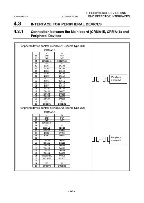
B-82725EN-2/05 CONNECTIONS4. PERIPHERAL DEVICE ANDEND EFFECTOR INTERFACES 4.3INTERFACE FOR PERIPHERAL DEVICES4.3.1Connection between the Main board (CRMA15, CRMA16) andPeripheral Devices-2NDEND EFFECTOR INTERFACESControl unit (peripheral device control interface A1)+24FConnector pin No.CRMA15 (49、50)Peripheral deviceDI101 DI102 Receiver circuit3.3kRV CRMA15 (01) CRMA15 (02) DI103DI104 RV DI105 RV DI106 RV DI107 RV DI108 RV SDICOM1 RV DI109 RV DI110 RV DI111 RV DI112 RV DI113 RV DI114 RV DI115 RV DI116 RV DI117 RV DI118 RV DI119 RV DI120 RV SDICOM2RVCRMA15 (03) CRMA15 (04) CRMA15 (05) CRMA15 (06) CRMA15 (07) CRMA15 (08) CRMA15 (19) CRMA15 (09) CRMA15 (10) CRMA15 (11) CRMA15 (12) CRMA15 (13) CRMA15 (14) CRMA15 (15) CRMA15 (16) CRMA15 (22) CRMA15 (23) CRMA15 (24) CRMA15 (25) CRMA15 (20)CRMA15 (17、18)0VNOTEIn this diagram, common voltage of input devices is +24V.RVRV4. PERIPHERAL DEVICE ANDEND EFFECTOR INTERFACES CONNECTIONS B-82725EN-2/05Control unit (peripheral device control interface A1)DOSRC1Connector pin No.CRMA15 (31,32)Driver circuitDVDO101CRMA15 (33)Peripheral device+24V 0V+24V regulatedpower supplyLOADRELAYDO102 DO103 DO104 DO105 DO106 DO107 DO108DVDVDVDVDVDVDVCRMA15 (34)CRMA15 (35)CRMA15 (36)CRMA15 (37)CRMA15 (38)CRMA15 (39)CRMA15 (40)CRMA15 (17、18)LOADLOADLOADLOADLOADLOADLOAD 0VA maximum output current per DO point is 0.2 A.B-82725EN-2/05CONNECTIONS 4. PERIPHERAL DEVICE AND END EFFECTOR INTERFACESControl unit (peripheral device control interface A2)+24F Connector pin No.CRMA16 (49、50)Peripheral deviceXHOLD RESET Receiver circuit3.3kRVCRMA16 (01)CRMA16 (02)CRMA16 (03)CRMA16 (04)CRMA16 (05)CRMA16 (06)CRMA16 (07)CRMA16 (08)CRMA16 (19)CRMA16 (17、18).RVRVRVSTARTRVENBLPNS1PNS2PNS3PNS4SDICOM3RVRVRVRV0 VNOTEIn this diagram, common voltage of input devices is +24V4. PERIPHERAL DEVICE ANDEND EFFECTOR INTERFACES CONNECTIONS B-82725EN-2/05Control unit (peripheral device control interface A2)Connector pin No.Pe ripheral device+24V 0VDriver circuitDO109DVCRMA16 (31、32)CRMA16 (41)+24V regulatedpower supplyLOADRELAYDO110DO111DO112DO113DO114DO115DO116DO117DO118DO119DO120 CMDENBLFAULTBATALMBUSY DVDVDVDVDVDVDVDVDVDVDVDVDVDVDVCRMA16 (42)CRMA16 (43)CRMA16 (44)CRMA16 (45)CRMA16 (46)CRMA16 (47)CRMA16 (48)CRMA16 (26)CRMA16 (27)CRMA16 (28)CRMA16 (21)CRMA16 (33)CRMA16 (34)CRMA16 (35)CRMA16 (36)LOADLOADLOADLOADLOADLOADLOADLOADLOADLOADLOADLOADLOADLOADLOADCRMA16 (17、18)0VA maximum output current per DO point is 0.2 A.DOSRC2B-82725EN-2/05 CONNECTIONS4. PERIPHERAL DEVICE ANDEND EFFECTOR INTERFACES The following shows the connector interface of the optional peripheral device cables on the peripheraldevice side.CONNECTIONS B-82725EN-2/054. PERIPHERAL DEVICE ANDEND EFFECTOR INTERFACES 4.3.2Connection between the Process I/O Board MA andPeripheral DevicesNOTE1 The peripheral device connection cable is optional.2 The DOSRC3 pin of CRMA52A and CRMA52B supply power to the drivers (connect all pins).B-82725EN-2/05CONNECTIONS 4. PERIPHERAL DEVICE AND END EFFECTOR INTERFACESControl unit +24F Connector pin No.Peripheral device (Peripheral device controlinterface:B1)DI121RVDI122RVDI123RVDI124RVDI125RVDI126RVDI127RVDI128RVDI129RVDI130RVCOM1RV+24E B Common-level change-over setting pin (ICOM1) ACRMA52A (49、50)CRMA52A (01)CRMA52A (02)CRMA52A (03)CRMA52A (04)CRMA52A (05)CRMA52A (06)CRMA52A (07)CRMA52A (08)CRMA52A (09)CRMA52A (10) CRMA52A (17、18)0V0V(This common voltage is for 24V.)DOSRC3Driver circuitDVDO121Connector pin No.CRMA52A (31、32)CRMA52A (33)EXT24V+24V0V+24V regulatedpower supplyLOADRELAYDO122 DO123 DO124 DO125 DO126 DO127 DO128DVDVDVDVDVDVDVCRMA52A (34)CRMA52A (35)CRMA52A (36)CRMA52A (37)CRMA52A (38)CRMA52A (39)CRMA52A (40)CRMA52A (29、30)0VLOADLOADLOADLOADLOADLOADLOADEXT0VNOTEIn this diagram, common voltage of input device is 24V.4. PERIPHERAL DEVICE ANDEND EFFECTOR INTERFACES CONNECTIONS B-82725EN-2/05 Control unit +24F Connector pin No.Peripheral device(Peripheral device control interface:B2)DI131RVDI132RVDI133RVDI134RVDI135RVDI136RVDI137RVDI138RVDI139RVDI140RVCOM1RV+24E B ACRMA52B (49、50)CRMA52B (01)CRMA52B (02)CRMA52B (03)CRMA52B (04)CRMA52B (05)CRMA52B (06)CRMA52B (07)CRMA52B (08)CRMA52B (09)CRMA52B (10) CRMA52B (17、18)0VCommon-level change-over setting pin (ICOM2)(This common voltage isfor 24V.)DOSRC30VConnector pin No.EXT24V+24V0VDriver circuitDO129DVCRMA52B (31、32)CRMA52B (33)+24V regulatedpower supplyLOADRELAYDO130 DO131 DO132 DO133 DO134 DO135 DO136DVDVDVDVDVDVDVCRMA52B (34)CRMA52B (35)CRMA52B (36)CRMA52B (37)CRMA52B (38)CRMA52B (39)CRMA52B (40)CRMA52B (29、30)0VLOADLOADLOADLOADLOADLOADLOADEXT0VNOTEIn this diagram, common voltage of input device is 24V.CONNECTIONS 4. PERIPHERAL DEVICE AND END EFFECTOR INTERFACESThe following shows the connector interface of the optional peripheral device cables on the peripheral device side.ControllerCRMA 52A 010203040506070809101112131415161718DI 121DI 122DI 123DI 124DI 125DI 126DI 127DI 128DI 129DI 1300V0V19202122232425262728293031320V0VDOSRC3DOSRC3Peripheral device A133 DO 12134 DO 12235 DO 12336 DO 12437 DO 12538 DO 12639 DO 12740 DO 128414243444546474849 24F50 24FCRMA 52B 010203040506070809101112131415161718DI 131DI 132DI 133DI 134DI 135DI 136DI 137DI 1380V0V19202122232425262728293031320V0VDOSRC3DOSRC3Peripheral device A233 DO 12934 DO 13035 DO 13136 DO 13237383940414243444546474849 24F50 24FDI 139DI 140DO 134DO 133DO 135DO 136。