在线溶解氧数字式传感器使用手册
- 格式:pdf
- 大小:644.23 KB
- 文档页数:6
杭州联测自动化技术有限公司杭州联测自动化技术有限公司U-SIN-DO-7013-L X CN 2第2版溶解氧电极使用说明书前言●感谢您购买本公司产品。
●本手册是关于产品的各项功能、接线方法、设置方法、操作方法、故障处理方法等的说明书。
●在操作之前请仔细阅读本手册,正确使用本产品,避免由于错误操作造成不必要的损失。
●在您阅读完后,请妥善保管在便于随时取阅的地方,以便操作时参照。
注意●本手册内容如因功能升级等有修改时,恕不通知。
●本手册内容我们力求正确无误,如果您发现有误,请与我们联系。
●本手册内容严禁转载、复制。
●本产品禁止使用在防爆场合。
版本U-S IN-DO-7013-LXCN2第二版2021年3月确认包装内容打开包装箱后,开始操作之前请先确认包装内容。
如发现型号和数量有误或者外观上有物理损坏时,请与本公司联系。
产品清单产品包装内容目录第一章产品概述 (1)第二章主要特点 (2)第三章技术参数 (3)第四章电气连接 (4)第五章溶解氧电极保存和维护 (5)第六章质保及售后服务 (7)第七章通讯协议 (8)7.1信息帧格式 (8)7.2寄存器数据格式 (9)7.3参数设置 (10)7.4常见指令集【HEX】 (11)7.5执行用户命令 (12)7.6用户命令错误代码返回 (13)7.7设备状态代码 (14)第一章产品概述第一章产品概述我司针对养殖行业设计的DO数字传感器,带RS485数字接口,可用于测量量程范围内水溶液体系中DO值的变化情况。
其带有标准RS485Modbus RTU协议接口功能,可以与上位机进行远程通讯。
第二章主要特点第二章主要特点●隔离电源设计,数据稳定性,抗干扰能力强成熟的传感器制造工艺,可靠性高,长期工作稳定性好使用耐久性溶解氧电解液配方,维护周期延长数字接口方式●通讯方式:RS485接口*1●通讯速率:4800/9600(默认)/14400/19200可选通讯协议:Modbus-RTU协议●溶解氧DO支持自动温度、手动大气压力,海水盐度补偿温度补偿范围:0.0–60.0℃●温度修正范围:±0.5℃大气压力补偿范围:600.0–800.0mmhg海水盐度补偿范围:0–40.0ppt第三章技术参数第三章技术参数第四章电气连接第四章电气连接第五章溶解氧电极保存和维护第五章溶解氧电极保存和维护(1)电极保存:电极长时间不用时,请将膜头内药水倒掉,并保持腔体干爽,电极膜套+橡胶套,用于保护膜头顶部透气膜,请勿丢弃(2)配件更换周期电极膜套:建议6个月进行更换电解液:建议3-6个月周期进行更换更换(3)维护-检查旧电极膜套旋开电极膜套,观察电极膜套头部-透气膜,检查其外观是否完整无瑕疵,如破损则需更换新的膜套。
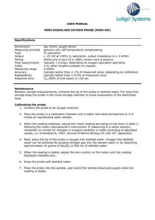
USER MANUALMINI DISSOLVED OXYGEN PROBE(MINI-DO)SpecificationsDimensions dia 15mm, length 90mmMeasuring principle galvanic cell, self temperature compensatingType % saturationOutput c. 25 mV at 100% O2 saturation, output impedance is c. 2 kOhm Wiring White wire is zero (0 or GND,) brown wire is positiveFlow requirements typically 1 cm/sec, depending on oxygen saturation and tempCable 3 m, other lengths available on requestMeasuring range 0-200%Accuracy typically better than ± 1% of measured value, depending on calibration Repeatability typically better than ± 0.5% of measured valueResponse time T90 (90% of end value) is <20 secMaintenanceBetween sample measurements, immerse the tip of the probe in distilled water. For long-time storage keep the probe in the moist storage chamber to avoid evaporation of the electrolyte fluid.Calibrating the probe1.Connect the probe to an oxygen analyzer.2.Place the probe in a calibration chamber with a water saturated atmosphere or in amixed air-equilibrated water sample.3.When the reading stabilizes, adjust the meter reading according to the chart in table 1,following the meter manufacturer’s instructions. If measuring in a saline solution,remember to correct for changes in oxygens solubility in water according to tabulated values, i.e. Green&Carrit, 1967. Journal of Marine Biology 25:140-147 (appendix).4.Next, place the tip of the probe in oxygen free distilled water. Oxygen free distilledwater can be achieved by purging nitrogen gas into the sample water or by dissolving approximately 10 grams of Na2SO3 in 500 mL of distilled water.5.When the reading is stable, adjust the zero control on the meter until the readingdisplayed indicates zero.6.Rinse the probe with distilled water.7.Place the probe into the sample, and record the sample dissolved oxygen when thereading is stable.Table 1. Table of oxygen saturation in waterTemperature Air saturated water Atmospheric pressure (deg C) (ppm or mgO2 l-1) (mmHg)10 11.3 157.311 11.1 157.112 10.8 156.913 10.6 156.714 10.4 156.515 10.2 156.316 10.0 156.017 9.7 155.818 9.5 155.619 9.4 155.420 9.2 155.221 9.0 154.922 8.8 154.723 8.7 154.424 8.5 154.125 8.4 153.826 8.2 153.527 8.1 153.228 7.9 152.829 7.8 152.530 7.6 152.235 7.1 150.040 6.6 148.045 6.1 145.5 Changing membranesChanging the membrane should not be necessary during normal use, unless it has been damaged or got very dirty. A damaged or dirty membrane will result in poor performance and erroneous readings, and eventually will require changing.For changing the membrane, follow the procedure as explained in the following pages.Membrane replacement for the MINI-DO oxygen probeClean the probe, unscrew the cap and press a knife into the gap between the ring and the cap to remove the ring. Discard the old membrane, clean and dry the parts. Then proceed as follows:1) Place the ring, chamfered edge down, into the base2) Place a new membrane on the base above the ring.3) Place the guide over the base, and4) place the cap in the hole in the guide5) Press the cap firmly down by hand6) Fill the cap with electrolyte fluid and screw it slowly up onto theprobeExcess electrolyte fluid should dribble from the thread。
溶解氧标定溶解氧标定必须在已知氧浓度的环境中进行。
YSI 550A溶氧仪可用mg/L或%饱和度来标定。
以下是这两种方式的标定步骤。
标定前要准确标定YSI 550A,你需要知道以下资料:1.被测水样的大概盐度。
新鲜淡水的盐度大约为零,海水盐度约为35ppt。
如果你不知水样的盐度,可以用YSI 30盐度一电导一温度仪来测得盐度值。
2.对于在%饱和度模式下标定,需要知道你所处位置的海拔高度(英尺)。
这些资料可从互联网或者当地机场或气象台获得。
如果要从米转化到英尺,除以0.3048要得到最佳结果:1.每次使用前都标定仪器,以防止漂移。
溶解氧读数取决于标定。
2.在与样品温度相差不超过±1 0℃范围内进行校正。
用%饱和度标定:1.确定仪器标定室内的海绵是湿润的。
把探头插入标定室。
2.打开仪器,等待约15—20分钟,让仪器预热及读数稳定。
3.同时按下并释放上箭头和下箭头键,进入标定菜单。
4.按下Mode键直至“%”作为氧气单位出现在屏幕右侧。
然后按下ENTER。
5.LCD屏幕上会提示你输入以百英尺为单位的当地海拔高度。
用箭头键增加或碱少输入的海拔高度,当正确的海拔高度出现在LCD上时,按下ENTER键。
例如:输入数字12代表1200英尺。
6.CAL将显示在屏幕左下角,右下端则显示校正值,主显示栏则显示DO读数(标定前)。
一旦当前溶解氧读数稳定,按下ENTER键。
7 .LCD将提示你输入被测水样的近似盐度,输入0至70(ppt)数字。
用箭头键可增加或减少盐度设定数字。
当LCD显示正确盐度时按ENTER键。
仪器将返回至正常操作状态。
用MG/L来标定1.打开仪器,等待约15—20分钟,让仪器预热及读数稳定。
2 将探头放入已知mg/L渎数的溶液,在整个标定过程中以最少1/2英尺每秒(16厘米每秒)的频率在水样中持续搅拌或晃动探头。
3.同时按下并释放上箭头和下箭头键,进入标定菜单。
4.按下Mode键直至“mg/L”作为氧气单位出现在屏幕右侧。
![[E+H] CM42-溶氧标定 说明书](https://uimg.taocdn.com/065f70cbd5bbfd0a795673a7.webp)
BA382C/07/zh/POD 有效版本:软件版本20.02.01操作指南Liquiline M CM42用于氧测量的带数字传感器二线制变送器第2部分:操作操作原理图 1: 按下软键:直接选择菜单图 2: 旋转浏览器:在菜单中移动光标图 3: 按下浏览器:选择功能图 4: 旋转浏览器:改变数值图 5: 按下浏览键:接受新数值操作原理1.通过按下相关软键直接选择菜单。
2.通过旋转浏览器,在菜单中移动光标。
3.按下浏览器并选择期望的功能。
4.通过旋转浏览器改变数值。
5.按下浏览器以接受新数值。
Liquiline M CM42目录1 显示屏 . . . . . . . . . . 4 1.1 总览 . . . . . . . . . . . . . . 4 1.2 状态信息 . . . . . . . . . . . . 42 有关软件描述的提示 . . . . 5 2.1 设置类型 . . . . . . . . . . . . 5 2.2 编辑表格 . . . . . . . . . . . . 5 2.3 用户管理 . . . . . . . . . . . . 53 测量(MEAS) . . . . . . . . 64 指定参数(测量参数). . . . 6 4.1 菜单结构,顶级层 . . . . . . . . 6 4.2 传感器 . . . . . . . . . . . . . 6 4.3 基本设置 . . . . . . . . . . . . 9 4.4 显示屏 . . . . . . . . . . . . . 11 4.5 快捷设定 . . . . . . . . . . . . 125 设备诊断(诊断). . . . . .14 5.1 菜单结构,顶级层 . . . . . . . . 14 5.2 错误/信息 . . . . . . . . . . . 14 5.3 传感器状态 . . . . . . . . . . . 14 5.4 传感器信息 . . . . . . . . . . . 15 5.5 设备信息 . . . . . . . . . . . . 16 5.6 维修服务 . . . . . . . . . . . . 176 标定(CAL). . . . . . . . .17 6.1 标定类型 . . . . . . . . . . . . 17 6.2 标定 . . . . . . . . . . . . . . 18 6.3 标定菜单 . . . . . . . . . . . . 187 通讯 . . . . . . . . . . .20 7.1 周期性数据交换 . . . . . . . . . 20 7.2 非周期数据交换 . . . . . . . . . 228 故障排除 . . . . . . . . .32 8.1 故障排除指导 . . . . . . . . . . 32 8.2 诊断消息 . . . . . . . . . . . . 32 8.3 过程错误(不显示信息) . . . . . 35 8.4 软件历史 . . . . . . . . . . . . 36索引 . . . . . . . . . . .37 Endress+Hauser显示屏Liquiline M CM424Endress+Hauser1显示屏1.1总览1.2状态信息图 6: 本地显示(测量模式)123状态行显示和设置区分配软键Liquiline M CM42有关软件描述的提示Endress+Hauser52有关软件描述的提示2.1设置类型•显示域-数值仅供读取,不能改变。
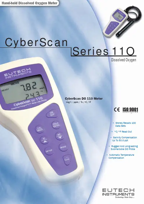
CyberScan DO 110 Metermg/l / ppm / % / o C / o FDissolved OxygenHand-held Dissolved Oxygen Meter• Stores/Recalls 100 Data Sets • °C/°F Read Out • Salinity Compensation Up To 50.0 ppt • Rugged And Long-lasting Submersible DO Probe • Automatic Temperature CompensationCyberScanSeries11ODistributed By:1 Large customised LCD2 Hinge3 Galvanic probeEC-DO110/01K CyberScan DO 110 meter with 3 meter electrode, ECDOHANDYNEW and EC-WPDRYKITEC-DO110/02K CyberScan DO 110 meter with 8 meter electrode and EC-WPDRYKITEC-DOHANDYNEW Submersible dissolved oxygen electrode with 3-metre cable (17 x 2.3cm)EC-POUCH-02Carrying pouch for meter01X241603Membrane & O-Ring (Pack of 5) 15X241402Assembled Membrane Cap Housing 15X241502Membrane Removal Tool 15X241504Electrode Guard Removal Tool 01X211226DO Refilling Electrolyte (60 ml)Dissolved Oxygen Range 0.00 - 19.99 mg/l or ppmResolution 0.01 mg/l ; 0.01 ppm Accuracy ±1.5% of full scale% Saturation Of Oxygen Range 0.0 - 199.9%Resolution 0.1%Accuracy ±1.5% of full scaleMeter Temperature Range -10 to 110 o C (14-230.0 o F)Resolution 0.1 o C / 0.1 °F (14 to 199.9 °F);1.0 °F (200 to 230 °F)Accuracy ± 0.5 o C (± 0.9 o F)Salinity Correction Range 0.0 - 50.0 pptResolution 0.1 ppt Method Manual input andautomatic correctionBarometric Pressure Range 500 to 1499 mm Hg or Correction 66.6 to 199.9 kPAResolution 1 mm Hg or 0.1 kPA Method Manual input andautomatic correctionProbe Galvanic Probe Operating Range 0 to 50 o C Response Time 40 seconds to achieve 93% of the reading No. Of Calibration Points One or two point at 0 % (Zero solution) and/or100% (in saturated air) or in air saturated waterMemory 100Hold Function Yes Auto-Off Selectable Display Custom LCD Power Requirements 4 ‘A AA ’ batteries; AC/DC adapter 9V , 50 mA Battery Life > 200 hours Temperature Compensation Automatic Operating Range 0 to 50 o C Dimension / Weight Meter: 18 x 9 x 4cm ; 220gBoxed: 24 x 23 x 7cm ; 600gThe CyberScan DO 110 Dissolved Oxygen meter is equipped with an Application Specific Integrated Circuit (ASIC). The ASIC mi-croprocessor provides many advanced features that offer users flexibility through customisable setup functions, while maintaining a user-friendly interface.MEMORYand secondary (temperature) values measured, complete with mode and measurement units. Graphic symbols and error message codes provide user comprehensive information for easy and trouble-free operation.ELECTRODE WITH BUILT-IN TEMPERATURE SENSORbe polarised as is the case with amperometric electrodes. The rugged galvanic electrode is optimised for quick response and is able to withstand the rigours of portable use. It requires little or no maintenance and has a built-in automatic temperature compensator. Includes an integral 3 or 8 metre waterproof cable.ELECTRODE DIAGNOSISuser to check on the accuracy of readings.INNOVATIVE DESIGNEutech Instruments hand-held meters are ergonomically designed for field operation and include a sturdy hinge for bench top measurements. Connections for the probe and optional AC adapter can be easily accessed.WARRANTY3 years and electrodes for 6 months.The CyberScan series are registered under U.S. Patent #354,921. Patents outside U.S. are pending.Note: We reserve the right to make changes, improvements and modifications to products shown. ************************Singapore ◆ USA ◆ Netherlands ◆ Malaysia ◆ ChinaP O R 08X 233206 9/05 R e v 4。
Products Solutions Services操作手册CCS120DMemosens数字式总氯传感器BA01950C/28/ZH/01.19714314962019-01-31CCS120D 目录Endress+Hauser 3目录1文档信息 (4)1.1安全图标 (4)1.2信息图标 (4)2基本安全指南 (5)2.1人员要求 (5)2.2指定用途 (5)2.3工作场所安全 (6)2.4操作安全 (6)2.5产品安全 (6)3产品描述 (7)3.1产品设计 (7)4到货验收和产品标识 (10)4.1到货验收 (10)4.2产品标识 (10)5安装 (12)5.1安装环境 (12)5.2安装传感器 (14)5.3安装后检查 (20)6电气连接 (20)6.1连接传感器 (20)6.2确保防护等级 (21)6.3连接后检查 (21)7调试 (22)7.1功能检查 (22)7.2向覆膜帽中充注电解液 (22)7.3传感器极化 (22)7.4传感器标定 (22)8诊断和故障排除 (24)9维护 (26)9.1维护计划 (26)9.2维护任务 (26)10维修 (31)10.1备件 (31)10.2返厂 (31)10.3处置 (31)11附件............................3211.1设备专用附件......................3212技术参数.......................3312.1输入..............................3312.2性能参数..........................3412.3环境条件..........................3412.4过程条件..........................3512.5机械结构..........................3513在Cl. I Div. 2防爆区中安装和使用传感器....................36索引. (38)文档信息CCS120D 1 文档信息1.1 安全图标1.2 信息图标1.2.1 设备上的图标4Endress+HauserCCS120D 基本安全指南Endress+Hauser52基本安全指南2.1 人员要求仅允许经培训的专业技术人员进行测量系统的安装、调试、操作和维护。
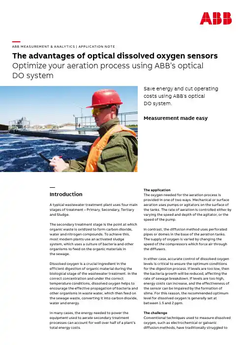
—A B B M E A SU R EM ENT & A N A LY TI C S | A PPLI C ATI O N NOTEThe advantages of optical dissolved oxygen sensors Optimize your aeration process using ABB’s optical DO systemSave energy and cut operatingcosts using ABB’s opticalDO system.Measurement made easy—IntroductionA typical wastewater treatment plant uses four main stages of treatment – Primary, Secondary, Tertiary and Sludge.The secondary treatment stage is the point at which organic waste is oxidized to form carbon dioxide, water and nitrogen compounds. To achieve this, most modern plants use an activated sludge system, which uses a culture of bacteria and other organisms to feed on the organic materials inthe sewage.Dissolved oxygen is a crucial ingredient in the efficient digestion of organic material during the biological stage of the wastewater treatment. In the correct concentration and under the correct temperature conditions, dissolved oxygen helps to encourage the effective propagation of bacteria and other organisms in waste water, which then feed on the sewage waste, converting it into carbon dioxide, water and energy.In many cases, the energy needed to power the equipment used to aerate secondary treatment processes can account for well over half of a plant’s total energy costs.The applicationThe oxygen needed for the aeration process is provided in one of two ways. Mechanical or surface aeration uses pumps or agitators on the surface of the tanks. The rate of aeration is controlled either by varying the speed and depth of the agitator, or the speed of the pump.In contrast, the diffusion method uses perforated pipes or domes in the base of the aeration tanks. The supply of oxygen is varied by changing the speed of the compressors which force air through the diffusers.In either case, accurate control of dissolved oxygen levels is critical to ensure the optimum conditions for the digestion process. If levels are too low, then the bacteria growth will be reduced, affecting the rate of sewage breakdown. If levels are too high, energy costs can increase, and the effectiveness of the sensor can be impaired by the formation of slime. For this reason, the recommended optimum level for dissolved oxygen is generally set at between 1.5 and 2 ppm.The challengeConventional techniques used to measure dissolved oxygen, such as electrochemical or galvanic diffusion methods, have traditionally struggled tomaintain accurate measurement over long periods of time without frequent recalibration due to sensor drift.Drawbacks such as limited membrane life havemade it difficult to achieve long-term accuracy and reliability. Moreover, the need for electrochemical sensors to be inspected, serviced and recalibrated, in some cases as often as every two weeks, adds to the overall cost of ownership. Optical sensors have provided a much more stable measurement, but many types on the market are still slow to respond and require regular calibration due to degradation of the lumiphore material.Measuring DO levels within an aeration process can prove a challenge in such a harsh environment. With high-fouling water and high sediment loads passing through the secondary stage at a rapid flow rate, the instrument needs to be robust and reliable.In addition to this, installations can prove difficult as although the basic technology in aerationprocesses remain basically the same, the methods can vary from mechanical or surface aeration to diffusion. It can also be extremely inconvenient when a sensor needs to be frequently replaced.Finally, transmitter devices can be complicated to program and commission, with calibration details, serial numbers and lifetime indication requiring input.The solutionThese problems are overcome by ABB’s new ADS420 optical DO sensor. Able to be used standalone or as part of a complete aeration control system featuring other ABB equipment such as the ACQ580 variable frequency drive, the ADS420 can help to provide accurate and stable measurement of dissolved oxygen levels.Unlike other optical DO systems, the sensor can be deployed for extended periods of time without a need for calibration. Each sensor cap is individually calibrated and profiled to the lumiphorecharacteristics, which are continually monitored throughout the life of the sensor. This avoids the need for frequent recalibration.The sensor’s construction features lumiphore molecules embedded in a gas-permeable sensing foil element, a blue LED, a red LED, and photodiode. When the blue LED emits light, red photons are emitted, caused by excitation of the lumiphore molecules embedded in the gas-permeable sensing foil.Any oxygen molecules present in the foil quench the luminescence, causing a phase shift in the returned red light which is measured by the photodiode. This phase shift is measured by comparing thedifference between the original red reference light and the red light being returned. The higher the levelOxygen molecules react with the lumiphore foilLuminescence is quenched causing a phase shiftPhase shift is measured by the photodiode—Figure 1Optical sensors – how they workof dissolved oxygen present, the lower the amount of red light is returned.The DO concentration is calculated and relayed to the transmitter. The resulting information is then used to fine-tune dissolved oxygen levels to match the requirements of the process. By using the phase shift to measure the lifetime of the luminescence rather than its intensity, the sensor offers the highest accuracy and stability across the widest operating range.As the patented signal processing is up to five times faster than other optical systems, improved control of dissolved oxygen levels can be achieved, enabling a return on investment in as little as six months. Impervious to drift, the non-consumptive, non-reactive method is ideal for high-fouling environments and can withstand the harshest operating conditions.—What can ABB offer?Comprised of a sensor and multi-channel transmitter, ABB’s optical DO sensor system utilizes the latest advances in optical measurement technology to give you the highest levels of stability and accuracy for dissolved oxygen measurement.The AWT420 dual-channel transmitter provides true flexibility for measuring a wide variety of parameters in a single device. The AWT420 can be used with either analog or digital EZLink sensors, providing plug-and-play sensor connectivity, automatic sensor recognition/set-up and advanced predictive diagnostics. It features an SD port for data storage and graphical trending and is compatible with a range of communications, including HART, Ethernet, Modbus and Profibus. The Ethernet module contains an embedded webserver that enables the unit to be viewed remotely and fully controlled securely via a web browser. Configuration data and processdata can be downloaded via a secure FTP connection.Setting up the transmitter and sensor is easy. Simply connect the sensor using ABB’s EZLink connection and the transmitter will automatically configure the sensor set-up.Added simplicity is provided by the sensor’s smart sensing cap with automatic setup.The SmartCap comes pre-loaded with factory calibration coefficients, serial number, lifetime indication, and manufacture date which are automatically uploaded to the ADS420 opticalDO sensor.—Figure 2Comprised of a sensor and multi-channel transmitter, ABB’s optical dissolved oxygen system can deliversignificant savingsThe SmartCap is capable of up to 24 months of continuous operation, greatly reducing the requirement for maintenance. When the cap does need replacing, it will be as easy as the original installation – the calibration details will be pre-loaded and the transmitter will automatically recognize the new sensor.When cleaning is necessary, it can be cleaned and redeployed without calibration. For high-fouling applications, the sensor can be automatically cleaned using ABB’s auto-clean system. This system periodically injects a high pressure burst of air across the sensor surface to remove any fouling.The ADS420 sensor is available with a range of installation options, including dip mount systems, floating ball systems and chain mount immersion systems for open tank and channel installations, as well as a flow-through system for panel mount systems.As a way of boosting performance whilst minimising energy costs, the optical dissolved oxygen system is ideal for large-scale municipal and industrial wastewater treatment plants.It could also be used in any application where water must be cleansed before re-entering the water cycle, including aquaculture, dam or discharge monitoring and in food and beverage production processes.—A complete offering for aerationABB has extensive experience in the design, manufacture and lifelong support of aerationcontrol systems for water, wastewater and process applications. Additional products available includethe ACQ580 variable frequency drive, thermal massand electromagnetic flowmeters, pressure transmitters and the CM30 range of PID controllers.For more information contact your local sales representativeAN/ANALYTICAL/8-ENRev.A5.222—We reserve the right to make technical changes or modify the contents of this document without prior notice. With regard to purchase orders, the agreed particulars shall prevail. ABB AG does not accept any responsibility whatsoever for potential errors or possible lack of information in this document.We reserve all rights in this document and in the subject matter and illustrations contained therein. Any reproduction, disclosure to third parties or utilization of its contents – in whole or in parts – is forbidden without prior written consent of ABB AG. Copyright© 2022 ABBAll rights reserved—ABB Limited/measurement。
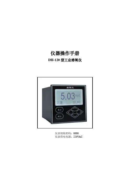
仪器操作手册DH-120型工业溶氧仪仪表初始密码:0000仪表供电电源:220V AC简要操作说明该手册包含了仪表所有的操作细节,以下的简要操作说明用于帮助用户尽快学会操作使用仪表。
1、仪表安装:将仪表固定在仪表柜的面板上或仪表箱内,防止太阳直射或水淋,连接好电源电缆线,先不要通电;2、电极安装:根据现场要求,将电极以沉入式(配沉入式护套管,请不要将电极电缆线直接浸泡在溶液中)、管道式(配不锈钢或PVC安装底座)、法兰式(配套特殊法兰),可查看P6页参考;3、摘除电极前面的橡胶保护帽,先不要将电极插入被测溶液中;4、将电极的接线端按所标号码与仪表后接线端标号一一对接;5、接通电源后进入标定菜单进行一点空气斜率标定,见P10;6、标定完成后将电极插入被测溶液中并安装好即可进行正常测量。
目录一概述 (4)二结构特征和工作原理 (4)2.1结构特征 (4)2.2工作原理 (4)三技术参数 (4)四功能特性 (5)五安装与电气连接 (5)5.1仪表安装 (5)5.2电极安装 (6)5.3仪表后接线板连接 (7)5.4电气连接 (7)六功能键说明 (8)七详细操作说明 (8)7.1开机 (8)7.2主菜单 (8)7.3子菜单 (8)7.4参数说明 (9)7.5标定说明 (9)八校验维护菜单 (10)8.1输出电流校验 (10)8.2测试继电器校验 (11)8.3修改密码 (11)8.4输出信号校验 (11)8.5售后服务 (11)九日常维护 (11)一概述DH-120型工业溶氧仪(以下简称仪表)是带微处理器的水质在线监测仪。
广泛用于工业水、生活水和污水处理,及养殖业等。
对水溶液中的含氧量进行连续监测和控制。
仪表采用LCD液晶显示屏;智能型中文菜单操作;具有电流或电压输出,测量范围自由设定,高低超限报警提示和两组继电器控制开关、迟滞量范围可调;自动或手动温度补偿,电极自动标定。
二结构特征和工作原理1、结构特征:整套测量系统主要由DH-120型仪表(二次表)和溶氧电极(一次表)两部分组成,溶氧电极接触被测溶液,仪表显示水溶液的含氧量和温度及工作状态。
JPBJ-608型便携式溶解氧测定仪使用说明书友情提示●欢迎您选用JPBJ-608型便携式溶解氧测定仪,请您在初次使用或长时间未使用本仪器前先详细阅读使用说明书,它将帮助您更好的使用本仪器。
●仪器超过一年必须送计量部门或有资格的单位复检,合格后方可使用。
●仪器的插座必须保持清洁、干燥,切忌与酸、碱、盐溶液接触。
●仪器可供长期稳定使用。
测试完样品后,应将电极储藏于煮沸冷却后的蒸馏水中,切忌将电极浸入亚硫酸钠溶液中,因为上述溶液一旦渗透到电极腔体内,会使电极性能恶化。
●新装电解液和薄膜后,需要极化60分钟后才能使用。
目 录1 JPBJ-608型便携式溶解氧测定仪安装.............................. 1.1 开箱......................................................................................1.2 JPBJ-608型便携式溶解氧测定仪安装............................. 1.3 电化学传感器(氧电极)的安装.................................. 1.4 氧电极的使用注意......................................................... 2 JPBJ-608型便携式溶解氧测定仪操作指南.......................2.1 简介.................................................................................2.1.1 术语解释...............................................................2.1.2 JPBJ-608型便携式溶解氧测定仪的特点........ 2.1.3 仪器主要技术性能............................................... 2.1.4 JPBJ-608型便携式溶解氧测定仪图示........... 2.1.5 使用溶解氧测定仪的方法.................................2.2 操作基本知识................................................................ 2.2.1 启动JPBJ -608型溶解氧测定仪................... 2.2.2 溶解氧电极测量................................................ 2.2.3 溶解氧电极的标定........................................... 2.2.4 其他仪器功能.................................................... 2.2.5 关闭JPBJ-608型便携式溶解氧测定仪...........222 56 7 7 7 7 10 1216 16 17 19 20 23 293 仪器的维护与维修............................................................... 3.1 维护............................................................................. 3.2 故障排除...................................................................... 3.3 电极的保养、维护和贮存........................................... 3.3.1 电极的保养和维护............................................. 3.3.2 溶解氧电极的储存......................................... 4 JPBJ-608型便携式溶解氧测定仪的附件信息................. 5 附录....................................................................................... 附录1:.............................................................................. 附录2:本系列产品订购信息 (30)303031313232 33 33 341 JPBJ-608型便携式溶解氧测定仪安装1.1 开箱在溶解氧测定仪(套装)装运包装箱中可找到以下部件:1. JPBJ-608型便携式溶解氧测定仪 1台2. DO-958-BF溶解氧电极 1支1.2 JPBJ-608型便携式溶解氧测定仪安装 仪器组成仪器整机图(图1)仪器由电子单元和电极系统组成,电极系统由极谱式氧电极(DO-958-BF型溶解氧电极)构成,可以同时测量溶液溶解氧值和温度值。
目录前言 (2)第一章产品简介 (5)1.1概述 (5)1.2原理简介 (5)1.3性能指标 (5)第二章安装 (6)2.1仪表安装 (6)2.2传感器与流通池安装 (7)2.3电气连接 (8)第三章仪表界面与操作 (10)3.1按键 (10)3.2主菜单 (11)3.3界面与操作 (12)3.3.1 基本说明 (12)3.3.2 密码设置 (13)3.3.3 滤波设置 (13)3.3.4 量程设置 (13)3.3.5 4mA校准 (13)3.3.6 20mA校准 (13)3.3.7 12mA测试 (13)3.3.8 高位报警 (13)3.3.9 低位报警 (13)3.3.10 零点标定 (14)3.3.11 斜率设置 (14)3.3.12 仪表信息 (14)3.3.13 载入出厂值 (14)第四章产品维护保养与常见问题 (15)4.1维护保养 (15)4.2常见问题 (15)免维护微量溶解氧分析仪前言非常感谢贵公司购买我公司生产的溶解氧在线分析仪。
本说明书对仪表可实现的各项功能、接线方法、设置方法、操作方法、故障处理方法进行了详尽的介绍。
在仪表投入运行之前,需详细阅读本说明书,正确掌握使用方法后再进行具体操作,避免由于错误操作造成不必要的损失,如果用本手册上所讲述的以外的方法操作,有时会损坏本仪表提供的保护,如果是因为违反这些注意事项而产生的故障及事故,我公司不承担责任。
使用仪表之前,请仔细阅读本说明书。
在充分理解的前提下,必须由现场相关电气专业类人员才能对仪表进行安装、操作和维护。
错误的安装或操作会导致仪表损坏或人身伤害。
本公司向用户承诺,本仪表供货时所应提供的硬件、附件在材质和制造工艺上都不存在任何缺陷。
从仪表购买之日起开始计算,在质保期内,若收到用户关于此类缺陷的通知,本公司对确实有缺陷的产品实行无条件免费维修或免费更换。
本公司对所有产品一律保证终身维修。
为遵循可持续发展的原则,本公司保留在事先不告知的情况下,对本说明书中所描述的各项性能参数进行修改的权利。
DO500 Loop-Powered Dissolved Oxygen TransmitterSpecificationsDO Range mg/L of oxygen: 0.00-20.00 mg/Lppm of oxygen: 0.00-19.99 ppm% saturation oxygen: 0.00 - 200.0 % Resolution 0.01 mg/L, 0.01 ppm, 0.1% Accuracy ±1.5% of full scaleTemperature Range 0 °C to 100 °C (32 °F to 212 °F) Temperature Resolution 0.1 °C (0.1 °F)Relative Temperature Accuracy ±0.5 °C (±0.9 °F)Temp Sensor Pt100(3 wire / 2 wire) Temperature Compensation Auto/ManualTemperature Coefficient 0 to 10°C (selectable)Salinity Compensation 0.0 -50.0 ppt (manual & automatic) Pressure Compensation 0.74 -3.00 bar; 55-225cm Hg;10.7- 43.5 psi (manual & automatic) Output 4.0-20.0mADisplay Dual Display Custom LCDPower Requirements 12 to 24V DC, maximum 600 Watt load Dimension 96 x 96 x 66 mm (3.78 x 3.78 x 2.6 inch) Weight 210 gCertifications CE Isolated Output prevents output interference caused by electrical noise or leakage from the input source. Out-of-range Output Current Indicator indicates an out-of-range measurement by emitting a 3.8mA output current.Hold Output Current Indicator to indicate `HOLD’ mode during calibration or set up mode. Scaleable 4-20 mA Current OutputPrimary and secondary display for simultaneous display of Dissolved Oxygen and Temperature values. Easy Push Button OperationAutomatic (with Pt 100) or manual Temperature CompensationPanel or Wall Mount, Nema 4x, IP65 Weatherproof HousingOffset Adjustment allows correction without sensor removalThis isolated output 4-20mA industrial transmitter is a sturdy microprocessor-based instrument that measures dissolved oxygen and temperature and transmits the dissolved oxygen output via a two-wire power supply loop. This transmitter has many user-friendly features—all of which are easily accessible via the water resistant membrane keypad. Ideal for connecting to a PLC for advanced control systems, the transmitter can also be connected to a recorder for a low-cost documentation system. The instrument housing is designed for panel or wall mounting.11751 Markon Dr.Garden Grove, CA 92841 USA Tel: 714-895-4344 Fax: 714-894-4839E-mail:*****************DO500 Loop-Powered DissolvedOxygen TransmitterOrdering InformationPart numberDescriptionDO500 1/4 DIN, 2-wire, loop-powered, 4-20mA, dissolved oxygen transmitter 972006 DO6400T/TC sensor wired for use with DO500 transmitter only972291 DO1200TC/H2M sensor with pre-installed 3/4" compression fitting wired for use withDO500 transmitter only。
s4-standard kit溶解氧测定仪说明书全文共四篇示例,供您参考第一篇示例:### 前言本说明书为S4-Standard Kit溶解氧测定仪的使用说明,它将帮助您正确、安全地操作溶解氧测定仪,以获取准确可靠的测定结果。
### 仪器概述S4-Standard Kit溶解氧测定仪是一种用于测定水体中溶解氧浓度的仪器,广泛应用于环境监测、水质监测、水产养殖等领域。
本仪器采用了先进的传感技术和数字化处理技术,具有高精度、高灵敏度、易操作等特点。
### 仪器组成S4-Standard Kit溶解氧测定仪包含以下组件:1. 主机:包括显示屏、操作按钮、数据接口等,用于显示测定结果和进行操作设置。
2. 传感器:用于测定水体中的溶解氧浓度。
3. 标准溶液:用于校准仪器。
4. 电源适配器:用于给主机供电。
### 使用方法1. 准备工作:将仪器连接电源适配器并打开开关,待仪器启动完成后,对传感器进行检查,确保传感器表面清洁无损。
2. 校准仪器:使用标准溶液对仪器进行校准,校准过程应准确无误,以保证测定结果的准确性。
3. 取样测定:将传感器放入待测水体中,等待一段时间后,仪器将显示出水体中的溶解氧浓度。
### 注意事项1. 仪器在操作前应进行充分的检查和校准,确保传感器和主机工作正常,避免因故障导致的误差。
2. 使用过程中应避免将仪器长时间暴露在阳光直射或潮湿环境中,以防损坏仪器。
3. 操作结束后,应将仪器及时清洗干净,存放在干燥通风的地方,以延长仪器的使用寿命。
### 维护保养1. 定期对仪器进行检查和维护,保持仪器的清洁和正常工作状态。
2. 存放时应将仪器放置在防尘、防湿、通风良好的环境中,远离化学腐蚀物品。
### 总结S4-Standard Kit溶解氧测定仪是一款先进的水质监测仪器,能够准确、可靠地测定水体中的溶解氧浓度。
正确使用和维护仪器,将有助于提高水质监测工作的效率和准确性。
希望本说明书能够帮助您顺利使用S4-Standard Kit溶解氧测定仪,取得理想的测定效果。
57900-18sc100™ LDO™溶解氧在线分析仪使用手册© 哈希公司Hach Company, 2003. 版权所有目录第一章技术指标........................................................................................................- 1 -第二章概述...............................................................................................................- 3 -2.1安全性信息 (3)2.1.1 警告图标 (3)2.2传感器概述 (3)2.3操作原理 (4)第三章安装...............................................................................................................- 5 -3.1机械安装 (6)3.1.1 控制器尺寸示意图......................................................................................- 6 -3.1.3 安装控制器.................................................................................................- 9 -3.2电气安装 (11)3.2.1 不带插头的电源线安装.............................................................................- 11 -3.2.2 电源线安装...............................................................................................- 11 -3.2.3 控制器端的电源接线.................................................................................- 12 -3.3继电器与模拟输出电流 (14)3.3.1 连接继电器...............................................................................................- 15 -3.3.2 连接模拟电流输出接线端子............................................................- 15 - 3.4连接传感器电缆. (16)3.5连接可选的网卡 (18)第四章系统启动......................................................................................................- 21 -4.1一般操作 (21)第五章操作.............................................................................................................- 22 -5.1使用键盘 (22)5.2控制器显示功能 (23)5.2.1 重要的按键...............................................................................................- 23 -5.2.2 调节显示屏的对比度.................................................................................- 24 -5.2.3 定制显示语言...........................................................................................- 24 -5.2.4 设置时间和日期........................................................................................- 25 - 5.3配置系统 (26)5.3.1 建立系统安全性........................................................................................- 26 -5.3.2 压力和海拔...............................................................................................- 27 - 5.4校准. (29)5.4.1 空气中校准...............................................................................................- 29 -5.4.2 样品校准——通过与温克勒(Winkler)滴定法进行比较..........................- 30 -5.4.3 样品校准——通过与手持式DO测定仪的结果相比较进行校准................- 32 -5.4.4 两个传感器同时进行校准..........................................................................- 33 -5.5输出选项 (33)5.5.1 保持/传输输出值.......................................................................................- 34 - 5.6继电器选项.. (35)5.7菜单结构 (38)第六章故障排除......................................................................................................- 44 -6.1错误代码 (44)6.2报警 (45)6.3一般的错误排除 (46)第七章维护.............................................................................................................- 47 -7.1维护计划 (47)7.2清洗传感器 (47)7.3清洁控制器 (47)7.4保险丝更换 (47)第八章订货信息......................................................................................................- 49 -第九章如何定购......................................................................................................- 50 -第十章维修服务.. (52)第十一章质量保证 (53)第十二章认证信息 (54)附录A MODBUS注册信息 (56)第一章规格下面的规格参数可能会在无预先告知的情况下有所更改。
中文Signet 2610 过程光学溶解氧传感器*3-2610.091*3-2610.091 Rev. 4 12/182Signet 2610 过程光学溶解氧传感器3Signet 2610 过程光学溶解氧传感器使用以下步骤校准传感器:1. 可选:读取传感器数据缓存超时寄存器49463并存储该值。
2. 将传感器数据高速缓存超时寄存器49463写入一个小于您想要的采样速率并大于1000毫秒的值。
这将确保您在稳定化过程中获得新的传感器读数。
3. 可选:读取温度单位寄存器40049和饱和单位寄存器40041并存储它们的值。
4. 将温度单位寄存器40049写入其默认值(1),并将饱和单位寄存器40041写入其默认值(117)。
5. 将校准模式开启命令(0xE000)写入传感器命令寄存器49305。
6. 必要时更新实时盐度和气压记录器。
7. 提示用户将探头置于100%饱和度环境中。
8. 读取氧气浓度和温度参数。
当这些值达到平衡时,将它们记录在各自的100%饱和度校准寄存器中。
将当前的实时盐度和气压读数写入各自的校准寄存器。
9. 提示用户将传感器置于0%饱和环境中。
当这些寄存器达到平衡时,将它们记录在各自的0%饱和校准寄存器中。
如果不执行零点校准,可以将这些寄存器设置为零或保留其先前的值。
注意:如果您的溶解氧传感器固件版本早于1.15,并且您没有进行零点校准,则必须将0%校准寄存器设置为零。
10. 将校准更新命令(0xE001)写入传感器命令寄存器。
传感器将计算新的斜率和偏移量,将当前时间写入最后一个用户校准时间寄存器,并将下一个用户校准时间寄存器设置为零(禁用)。
如果100%和0%饱和度下的浓度相等,则探针将返回带有代码的异常响应0x97(无效校准),并且不会尝试计算可能被零除的新斜率和偏移量。
如果斜率不在0.85和1.20之间,或者偏移量不在-0.2和+0.2之间,则探头将返回代码为0x97的异常响应(无效校准)。
JPB-607A便携式溶解氧分析仪使用说明书一、概述JPB-607型便携式溶解氧分析仪(以下简称仪器),主要是为方便用户携带到现场操作而设计的。
该仪器可分为传感器和电子单元两个部份。
传感器采用极谱型复膜氧电极。
电子单元为带有自动温度补偿的集成运算放大器组成。
仪器采用31/2位液晶显示可显示溶解氧值和温度。
二、技术参数2.1 仪器工作条件:2.1.1 环境温度:(O~4O)℃;2.1.2 相对湿度;不大干90%;2.1.3 被测样品温度:(O~40)℃;2.1.4 供电电源:9F22型9伏电池一节;2.1.5 除地磁场外,无显著电磁场影响。
2.2 主要技术指标:2.2.1 测量围:溶解氧:(0~20.0)mg.L-1 温度:(0~40)℃2.2.2 电子单元的准确度:±0.1mg/L±1个字2.2.3 仪器准确度:溶解氧:±0.1mg/L±1个宇(校准温度与测量温度相同)±0.5mg/L±1个字标准温度与测量温度相差±10℃时)温度:±1℃2.2.4传感器响应时间:不大于3Os(2O℃时90%响应)2.2.5传感器残余电流:不大于O.15mg.L-1±1个字;2.2.6电子单元的稳定性:在3h不超过±0.1mg/L±1个宇;2.2.7仪器稳定性:不超过±0.2mg.L-1±1个字/1h;2.2.8自动温度补偿围:(0~40)℃;2.2.9外形尺寸L×b×h,mm:165×72×35;2.10仪器重量(kg):0.3。
三、工作原理仪器由极谱型复膜氧电极与带有微处理机电子单元两大部分组成。
极化电压输出0.7伏左右电压,施加于氧电极上,银接电源正极,黄金接电源负极。
黄金电极与I-V转换单元的集成运算放大器连接。
在此单元中,来自于电极的电流讯号转换成电压讯号,同时对电极的温度系数作部份补偿,I-V单元的输出讯号,再送入温度补偿单元中,对电极温度系数进行全补偿,最后由数字显示测量结果。
SX751型pH/ORP/电导率/溶解氧测量仪使用说明书上海三信仪表厂SX700系列便携式测量仪1. SX711型pH/mV计2. SX712型ORP计3. SX713型电导率/TDS/盐度/电阻率测量仪4. SX716型溶解氧测量仪5. SX721型pH/ORP计6. SX723型pH/mV/电导率测量仪7. SX725型pH/mV/溶解氧测量仪8. SX726型电导率/溶解氧测量仪9. SX731型pH/ORP/电导率测量仪10. SX736型pH/mV/电导率/溶解氧测量仪11.SX751型pH/ORP/电导率/溶解氧测量仪目录1. 概述 -------------------------------------------------------------------------------------------------2. 技术参数 ------------------------------------------------------------------------------------------- 2.1. pH ------------------------------------------------------------------------------------------------- 2.2. ORP ---------------------------------------------------------------------------------------------- 2.3. 电导率 ------------------------------------------------------------------------------------------- 2.4. 溶解氧 ------------------------------------------------------------------------------------------- 2.5. 其它技术参数 ----------------------------------------------------------------------------------2.6. 工作条件 ----------------------------------------------------------------------------------------3. 仪器说明 ------------------------------------------------------------------------------------------- 3.1. LCD显示 --------------------------------------------------------------------------------------- 3.2. 操作键 -------------------------------------------------------------------------------------------3.3. 测量信息的储存、回显和清除 ------------------------------------------------------------4. pH测量 ---------------------------------------------------------------------------------------------- 4.1. 准备工作 --------------------------------------------------------------------------------------- 4.2. 仪器校准 ---------------------------------------------------------------------------------------- 4.3. 溶液测量 ---------------------------------------------------------------------------------------- 4.4. 参数设置 ---------------------------------------------------------------------------------------- 4.5. 注意事项 ---------------------------------------------------------------------------------------4.6. 自诊断信息 ------------------------------------------------------------------------------------5. ORP测量 ------------------------------------------------------------------------------------------- 5.1. 溶液测试 ---------------------------------------------------------------------------------------- 5.2. 注意事项 ----------------------------------------------------------------------------------------5.3. 参数设置 ----------------------------------------------------------------------------------------6. 电导率测量 ---------------------------------------------------------------------------------------- 6.1. 准备工作 --------------------------------------------------------------------------------------- 4 6 6 6 6 6 7 7 7 7 8 910 10 10 11 11 14 15 16 16 16 17 18 186.2. 仪器校准 ---------------------------------------------------------------------------------------- 6.3. 溶液测试 ---------------------------------------------------------------------------------------- 6.4. 重要说明 ---------------------------------------------------------------------------------------- 6.5. 参数设置 ---------------------------------------------------------------------------------------- 6.6. 注意事项 ----------------------------------------------------------------------------------------7. 溶解氧测量 ---------------------------------------------------------------------------------------- 7.1. 准备工作 --------------------------------------------------------------------------------------- 7.2. 仪器校准 --------------------------------------------------------------------------------------- 7.3. 水样测试 --------------------------------------------------------------------------------------- 7.4. 注意事项 --------------------------------------------------------------------------------------- 7.5. 参数设置 --------------------------------------------------------------------------------------- 7.6. 更换隔膜帽 ------------------------------------------------------------------------------------ 7.7. 零氧校准 --------------------------------------------------------------------------------------- 7.8. 盐度校准 --------------------------------------------------------------------------------------- 7.9. 气压设置 --------------------------------------------------------------------------------------- 8. 仪器成套性 ---------------------------------------------------------------------------------------- 9. 仪器保证事项 ------------------------------------------------------------------------------------- 1818182023242425252526282929303031附表Ⅰ 仪器参数设置一览表 附表Ⅱ 仪器恢复出厂设置一览表 附表Ⅲ 代码符号及缩写一览表 附表Ⅳ 氧在不同温度水中的饱和含量 附表Ⅴ 氧在不同气压中的饱和含量 附表Ⅵ 氧在不同海拔高度中的饱和含量1. 概述:感谢您购买和使用SX751型pH/ORP/电导率/溶解氧测量仪(以下简称仪器)。
在线溶解氧数字式传感器
用户手册
目录
一、设备应用环境说明 (3)
二、技术参数、功能和规格要求 (3)
1. 技术参数 (3)
2. 数据通信 (3)
3. 尺寸图 (5)
4. 产品规格 (6)
5. 产品维护指导 (6)
6. 配件和备件 (7)
7. 质量保证 (7)
8. 售后服务承诺 (7)
应用于水产养殖行业的溶解氧传感器,能够在水下深度 20cm 至 1000cm 工作,能适应海水或淡水水体中多微生物、鱼虾类、水草类、泥沙等环境条件。
2、通信协议
2.1Modbus 通信默认的数据格式为:9600、n、8、1(波特率 9600bps,1 个起始位,8 个数据位,无校验,1 个停止位)。
波特率等参数可以定制。
2.2信息帧格式
a) 读数据指令帧:
b) 读数据应答帧:
2.3 寄存器地址
注意:
a) 寄存器地址为根据 Modbus 协议定义的带寄存器类型的寄存器起始地址(括号中的 16进制表示的实际的寄存器起始地址)。
b) 更改传感器地址时,返回指令中的传感器地址为更改后的地址。
c) 读取数据时返回测量值的数据定义:
数据类型默认为:双字节整型,高字节在前;其他如浮点数类型可选。
2.4 命令示例
a) 设置设备 ID 地址
作用:设置电极的 Modbus 设备地址;
将设备地址 06 改为 01,范例如下
请求帧:06 06 20 02 00 01 E3 BD
应答帧:01 06 20 02 00 01 E2 0A
b) 开始测量指令
作用:获取测量探头的溶解氧值和温度;温度的单位为摄氏度,溶解氧的值为mg/l
请求帧:06 03 00 00 00 04 45 BE
应答帧:06 03 08 01 02 00 02 00 B0 00 01 14 B4
读数示例:
如:溶解氧值 01 02 表示十六进制读数溶解氧值,00 02 表示溶解氧数值带 2 位小数点;
温度值 00 B0 表示十六进制读数温度值,00 01 表示温度数值带 1 位小数点。
c) 校准指令
零点校准,作用:设定电极的溶解氧零点校准值;
请求帧:06 06 10 00 00 00 8C BD
应答帧:06 06 10 00 00 00 8C BD
斜率校准,作用:设定电极的溶解氧斜率校准值;此处斜率值校准在空气中进行。
请求帧:06 06 10 04 00 00 CD 7C
应答帧:06 06 10 04 00 00 CD 7C
2.5 错误响应
如果传感器不能正确执行上位机命令,则会返回如下格式信息:
a) CODE:01 –功能码错
03 –数据错
b) COM:接收到的功能码
3. 尺寸图
4. 产品规格
4.1 线缆信息
其引接定义为:
a) 红色线—电源线(12~24V)
b) 黑色线—地线(GND)
c) 蓝色线—485A
d) 白色线—485B
e) 裸露线—屏蔽线
4.2 线缆规格说明
考虑到线缆长期浸泡在水中(包括海水)或暴露在空气中,要求线缆具有一定的防腐蚀能力。
线缆外径Φ 6 mm,所有接口均要求做防水处理。
5.
5.1 电极的检测与维护
新电极和长期放置的电极,使用前需要进行电极极化,将电极通电,在空气中静置 30 分钟。
如果返回数值不准确,则需要进行以下操作:
对电极进行零点和斜率校准。
检查更换电解液。
返厂检查。
5.2 电解液和电极溶氧膜套的更换
a) 电解液的更换
垂直放置溶氧电极,小心旋下溶氧膜套。
用柔软的纸巾小心清洁玻璃体的前端。
用滴管往溶氧膜套中加入 1.5ml 的电解液,用手指轻弹溶氧膜套,确保电解液中没有气泡。
仔细查看溶氧膜套,任何溢出的电解液都需要用吸水纸小心吸去。
b) 电极膜套的更换
垂直放置溶氧电极,小心旋下溶氧膜套。
用柔软的纸巾小心清洁玻璃体的前端。
取一个新的膜头,重加入 1.5ml 的电解液,用手指轻弹溶氧膜套,确保电解液中没有气泡后旋紧膜头。
仔细查看溶氧膜套,任何溢出的电解液都需要用吸水纸小心吸去。
6.
此产品包括:
传感器 1 支
电解液 1 瓶
溶解氧膜头 1 个
说明书一份
合格证一张。