GM615双输入输出模块使用说明书
- 格式:pdf
- 大小:759.13 KB
- 文档页数:5
BEFORE USE ....Thank you for choosing M-System. Before use, please check contents of the package you received as outlined below .If you have any problems or questions with the product, please contact M-System’s Sales Office or representatives. ■PACKAGE INCLUDES:Discrete output module.......................................................(1) ■MODEL NO.Confirm Model No. marking on the product to be exactly what you ordered.■INSTRUCTION MANUALThis manual describes necessary points of caution when you use this product, including installation, connection and basic maintenance procedures.POINTS OF CAUTION■CONFORMITY WITH EU DIRECTIVE• Use dual-shield cables (Shinko Seisen Industry Model ZHY262 PBA) for the network. If it is not sufficient, use a ferrite core (Kitagawa Industries Model GRFC-13) for the network cable.• The equipment must be mounted inside the instrument panel of a metal enclosure.• The actual installation environments such as panel con-figurations, connected devices, connected wires, may af-fect the protection level of this unit when it is integrated in a panel system. The user may have to review the CE requirements in regard to the whole system and employ additional protective measures to ensure the CE conform-ity . ■POWER INPUT RATING & OPERATIONAL RANGE• Locate the power input rating marked on the product and confirm its operational range as indicated below:24V DC rating: 24V ±10%, approx. 45mA ■GENERAL PRECAUTIONS• Before you remove the unit or mount it, turn off the power supply and output signal for safety .• DO NOT set the switches on the module while the power is supplied. The switches are used only for maintenance without the power. ■ENVIRONMENT • Indoor use.• When heavy dust or metal particles are present in the air, install the unit inside proper housing with sufficient ventilation.• Do not install the unit where it is subjected to continuous vibration. Do not subject the unit to physical impact.• Environmental temperature must be within -10 to +55°C (14 to 131°F) with relative humidity within 30 to 90% RH in order to ensure adequate life span and operation. ■WIRING• Do not install cables close to noise sources (relay drive cable, high frequency line, etc.).• Do not bind these cables together with those in which noises are present. Do not install them in the same duct. ■AND ....• The unit is designed to function as soon as power is sup-plied, however, a warm up for 10 minutes is required for satisfying complete performance described in the data sheet.056 222 38 18SEN TRONIC AGCOMPONENT IDENTIFICATION■ FRONT VIEW■ SIDE VIEW■STATUS INDICATOR LED ID COLOR FUNCTIONPWR Green Turns on when the internal 5V is sup-plied normally .RUNGreenTurns on when the refresh data is re-ceived normally .■DISCRETE OUTPUT STATUS INDICATOR LED LED indicators shows the signal status.ON : LED ON (red)OFF : LED OFF■STATION ADDRESSThe left switch determines the sixteenths place digit, while the right switch does the ones place digit of the address.(Range: 01H to 3FH)Station Address Setting (x1)Station Address Setting (x16)■OPERATING MODE (*) Factory setting•Output at the loss of communication (SW1-7)SW1-7OUTPUT AT THE LOSS OF COMMUNICATIONOFF Hold the output (*)(maintains the last data received normally) ONReset the output (turned off)•Transfer rate (SW1-8)SW1-8TRANSFER RA TE OFF 12 Mbps (*)ON6 MbpsNote: Be sure to set unused SW1-1 through 1-6 to OFF .■TERMINATING RESISTORTo use the terminating resistor, turn the switch ON, and OFF to invalidate. (Factory setting OFF)■NETWORK, POWER SUPPLY TERMINAL ASSIGNMENT •Full-duplex communication4RXD+567123RXD–+24V 0V TXD+TXD–FGNO.ID FUNCTION, NOTES1TXD+Network (slave, transmission +)2TXD–Network (slave, transmission –)3FG FG4RXD+Network (master, transmission +)5RXD–Network (master, transmission –)6+24V Power input (24V DC)70VPower input (0V)•Half-duplex communication4TR +567123TR –+24V 0V NC NC FGNO.ID FUNCTION, NOTES 1NC No connection 2NC No connection3FG FG 4TR+Network 5TR–Network6+24V Power input (24V DC)70VPower input (0V)■OUTPUT TERMINAL ASSIGNMENT10 +24V 11Y112Y310V 2Y03Y213Y54Y414Y75Y615Y96Y816YB7YA17YD8YC9YE18YFNO.ID FUNCTION NO.ID FUNCTION 10V0V10+24V24V DC (common) 2Y0Output 011Y1Output 1 3Y2Output 212Y3Output 3 4Y4Output 413Y5Output 5 5Y6Output 614Y7Output 7 6Y8Output 815Y9Output 9 7YA Output 1016YB Output 11 8YC Output 1217YD Output 13 9YE Output 1418YF Output 15 TERMINAL CONNECTIONSConnect the unit as in the diagram below.■EXTERNAL DIMENSIONS unit: mm (inch)TERMINALS for Network, POWER TERMINALS for OUTPUT■CONNECTION DIAGRAM■ O utput Connection Example0V24V DCFG TXD– (NC)TXD+ (NC)RXD– (TR–)RXD+ (TR+)YD YB 0VYF Y9Y7Y5Y3Y1YE YC YAY8Y6Y4Y2+24V Y0Note 1: Terminal numbers in parentheses are for half-duplex communication model.Note 2: In order to improve EMC performance, bond the FG terminal to ground.Caution: FG terminal is NOT a protective conductor terminal.WIRING INSTRUCTIONS■SCREW TERMINAL Torque: 0.5 N·m■SOLDERLESS TERMINALRefer to the drawing below for recommended ring tongue terminal size. Spade tongue type is also applicable.Recommended solderless terminal:• Communication cablesApplicable wire size: 0.2 to 0.5 mm 2 (AWG 26 to 22) Recommended manufacturer: Japan Solderless Terminal MFG. Co., Ltd.• OthersApplicable wire size: 0.25 to 1.65 mm 2 (AWG 22 to 16) Recommended manufacturer: Japan Solderless Terminal MFG. Co., Ltd. or Nichifu Co., Ltd.COMMUNICATION CABLE CONNECTIONSMaster ModuleSlave ModuleSlave ModuleResistorResistorNote: Be sure to turn ON the switch of the terminating resistor located at both ends of the modules.ResistorResistor■ MASTER CONNECTION• Full-duplex communicationI/O DATA DESCRIPTIONS■DISCRETE OUTPUT Unused15• Di• DoOutput 0Output 1Output 2Output 3Output 15Output 7Output 8::: 0: OFF 1: ON。

Think-WiFi 快速使用手册2013-04-12Think-WiFi深圳圣湖高科通讯技术有限公司1 Think-WiFi模块简介1.1 产品简介1.2 产品技术规格:下表列出了Think-WiFi模块的主要特点:表1-1 产品技术规格项 目 参 数无线部分 无线标准 IEEE802.11b/g 802.11n forcast频率范围 2.412~2.484 GHz接收灵敏度 802.11b: -90 dBm @ 11Mbps (typical)802.11g: -70 dBm @ 54Mbps(typical)数据速率 802.11b: 1,2,5.5,11 Mbps802.11g: 6,9,12,18,24,36,48,54 Mbps调制方式 DSSS, OFDM, DBPSK, DQPSK, CCK, QAM16/64 输出功率 802.11b: 17±2 dBm(typical)802.11g: 15±1 dBm(typical)天线接口 IPX/微带硬件部分接口类型 UART/SPI接口速率 1200~460800 bps 工作电压 3.3±0.3 V工作电流 170mA (typical) 存储温度 -40~+85 ℃工作温度 -20~75 ℃外形尺寸 23*37mm环保认证 RoHS网络类型 Infra/Adhoc/AP软 件安全机制 WEP/WPA-PSK/WPA2-PSK 加密类型 WEP64/WEP128/TKIP/CCMP(AES) AP模式支持4个STA连接仅支持STA和AP间通信,不支持STA和STA间通信加密认证方式支持OPEN、WEP 工作模式 自动/命令 串口命令 AT+指令集 IP协议 IPv4/IPv6网络协议 TCP/UDP/ARP/ICMP/DHCP/DNS/HTTP/IGMP/PPPOE最大Socket连接 15TCP连接 最大连接数:8 最大Client数:8 最大Server数:3~4本端Server最大接入Client数:4 UDP连接 最大连接数5~6最高传输速率 44Kbytes参数配置方式支持最多4种参数配置方式:方式一、UART接口命令(AT指令模式) 方式二、SmartConfig一键模式 方式三、Web页面参数配置 方式四、Udp远程方式(* 要使用IGMP/PPPOE/IPv6功能请联系我们的技术支持获取更多帮助)1.3硬件说明 1.3.1 产品外形无线模块,外形图如下。
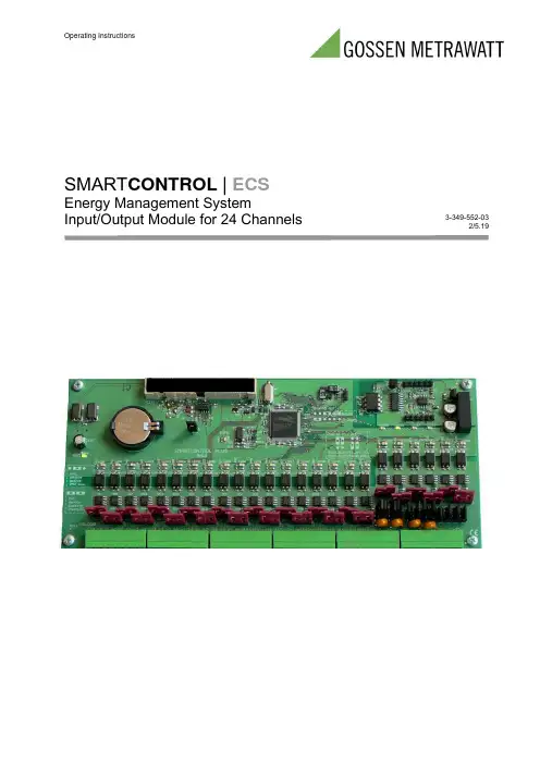
Operating InstructionsSMART CONTROL | ECSEnergy Management SystemInput/Output Module for 24 Channels3-349-552-032/5.19Table of Contents1.Input/Output Module for 24 Channels (3)1.1Jumper Designations and Functions (4)2.Input/Output Module for 24 Channels and SmartControl Manager (7)2.1Command Type IO24Analog (8)2.2Command Type IO24Meter (10)2.3Command Type IO24Relay (10)2.4Command Type IO24Status (11)2.5Backup Battery (13)3.Characteristic Values (14)4.Repair and Replacement Parts Service, Calibration Center and RentalInstrument Service (16)5Product Support Industry (16)2 GMC-I MesstechnikGmbH1. Input/Output Module for 24 ChannelsThe I/O module for 24 channels expands the SmartControl with 24 additional digital inputs (DI0 through DI23).Furthermore, ports DI18 through DI21 can be configured as switching outputs K1 through K4 by means of jumpers. Ports DI22 and DI23 can be configured as analog outputs with jumpers as well.The module is mounted with the help of the included accessories, and is connected to the expansion port at the SmartControl PCB (at the bottom in the picture) with the included cable.Please observe all safety precautions for assembly and the connection of ports included in the SmartControl user’s manual.GMC-I Messtechnik GmbH 34 GMC-I Messtechnik GmbH 1.1 Jumper Designations and FunctionsThe terminals for ports DI0 through DI23 are designated a and b. The terminals for the digital inputs, for example DI0, are designated a0 and b0. Jumpers for the active or passive digital input mode: If the ports are used as digitalinputs, either sensors with their own power supply or, e.g., floating contacts/reed contacts can be connected. For a more detailed description of this function please refer to the “Digital Inputs ” section in the SmartControl user’s manual. However, the digital input tariff and synchronization functions described in the user’s manu al are not available in this case.Digital in / option:Jumpers for selecting options for the last six digital inputs (DI18 through DI23). Ports DI18 through DI21 can be configured as switching outputs K1 through K4. For example, SV27/SV29 plugged onto 2-3,respectively, configures DI18 as floating NO contact K1. For a more detailed description of the relays please refer to the “Analog Inputs, Relays ” section in the SmartControl user’s manual. The jumpers required for selecting switching outputs K1 through K4 are:SV29/SV27, SV33/SV31, SV38/SV36, SV42/SV40.The following are then available at the terminals, for example for DI18 as switching output K1: DI18a and DI18b, the switching function is configured as a normally open contact (NO). Ports DI22 through DI23 can be configured as analog outputs.The jumpers required for selecting analog outputs ANA0 through ANA1 (command address: 0-1) are:SV37/SV39, SV41/SV43.Function selection for the analog outputs:Required jumpers for ANA0 -> SV30 SV28 SV26Required jumpers for ANA1 -> SV35 SV34 SV32Example ANA0 as 0-10V output -> Jumper plugged onto SV28, SV26.The following are then available at the terminals for DI22:DI22a analog plus (+)DI22b analog ground (-)Example ANA0 as 0-20mA output -> no jumper plugged onto SV30, SV28, SV26The following are then available at the terminals for DI22:DI22a analog plus (+)DI22b analog ground (-)The following combinations are possible for both analog outputs:ANA0 ANA1 Use0-10V 0-10V Common ground0-20mA - Common ground- 0-20mA Common ground0-20mA 0-20mA Electrical isolation required0-10V 0-20mA Electrical isolation required0-20mA 0-10V Electrical isolation requiredWithin this context, electrical isolation means, for example, that the ground terminals at ANA0 and ANA1 are neither connected with each other nor with any external ground terminals.GMC-I Messtechnik GmbH 56GMC-I Messtechnik GmbH Further components:Jumper SV44 (always plugged in) disconnects the reset cable from the main PCB. Briefly unplugging the jumper results in a reset.Jumper SV45 (always open) is used to reinitialize the BBSRAM.LEDs 1 through 24 (red): indicates pulses at inputs DI0 through DI23.LED 30 (green) DIAG, blinks approx. once per second for normal operation.LEDs 25 through 28 (green): status display for the switching outputsLED on = contact closed LED off = contact openSV1 is the interface to the main PCB at the SmartControl (expansion port).The jumpers for active and passive inputs correspond to those of the SmartControl (refer to the “Digital Inputs ” section in the SmartControl user’s manual).The connection terminals for DI0 through DI23 are numbered 49 through 96.2. Input/Output Module for 24 Channelsand SmartControl ManagerThe input/output module for 24 channels is configured with SmartControl Manager software. The “IO24Meter” spreadsheet can be accessed under calibrat ion in the SmartControl Manager:Factor, unit of measure and meter reading can be entered. These entries are written to the SmartControl after c licking the “Accept” button, and all entries can be returned to their default values by clicking the “Reset” button.Click the current reading for setting the meter readings. Change the reading and acknowledge with enter. Save the changes to the SmartContr ol with the button …...“ which then appears.The units of measure entered here are used automatically when the meters are read.Units of measure and meter factors can only be changed here.One of the following IO24 commands can now be entered to a new program in the SmartControl Manager under menu item “programming”:The symbols are located in the middle at the top of the main window.Just click the symbols and drag them to an empty command field. “D/A” means analog, “123” means meter, the third symbol represents a relay, “I/O” means status.GMC-I Messtechnik GmbH 78 GMC-I Messtechnik GmbH 2.1 Command Type IO24AnalogThe address determines the output channel (ANA0=0 or ANA1=1). The command variable determines the analog output value. Any desired reference can be used.Only analog values within the output range are displayed. Larger and smaller values are shortened accordingly.Example: the command variable has the value 15, whereas the value 10 is shown as analog value.The value range of the input value can be further adjusted to the output range by adjusting the slope, etc. of the command variable.By clicking …Test“ a window opens. Upon entering a test value and clicking the “Start”button, the analog output is set to the corresponding value. If no test value is entered, the command variable is used.GMC-I Messtechnik GmbH 910 GMC-I Messtechnik GmbH 2.2 Command Type IO24MeterThe name can be changed in the bottom field in the meter command, and selection can be made as to whether or not writing to flash memory will take place.Furthermore, it can be specified for each input whether or not this value will be stored to flash memory.Attention : If changes are made here (clear or add meter, or use another input), another ID is assigned to the data as of this point in time which must be given special consideration during read-out because the configuration of the data has been changed! Further settings, for example unit of measure, can be entered under “Calibration” -> “IO24Meter”.2.3 Command Type IO24RelayPlease refer to the “SmartControl Manager, Command Type Relay ” section in the user’s manual for the SmartControl with regard to this command type.The functions are the same, only the addresses for DI18 through DI21 in the address field of this command type are 0-3.2.4 Command Type IO24StatusAn IO24 status command can be created for recording status changes.The status command queries all digital inputs at the clock-pulse rate of the measuring cycle. The address field has no significance in this case.Status changes are saved at the clock-pulse rate of the measuring cycle at most. However, data are always saved at the clock-pulse rate of the saving cycle, regardless of whether a status change has taken place or not.By clicking …Test“ -> …Start“, all digital inputs are queried.GMC-I Messtechnik GmbH 1112GMC-I MesstechnikGmbHThe digital inputs u nder the network ID are individually available under menu item …Network Variables“ and can be used for example as reference for system commands.The …Network Variables “ are automatically created with pre-defined values by theSmartControl under …IO24“ commands. They are automatically assigned a new virtual ID which is calculated as follows::Virtual ID = 10,000 + ID of the IO24 command x 100 + No. value.Example for the IO24 status command of digital input 12:Virtual ID = 10,112 = 10,000 + 1 x 100 + 12The values which have been saved to memory can be queried under menu item …Table“ -> …Read-in “.The status of the other inputs is also saved by this command for channel 12.2.5 Backup BatteryThe battery on the PCB is a lithium round cell, type CR2032 3V.It serves to maintain the meter readings in the event of a power failure.If the instrument is stored for a lengthy period of time without being used, we recommend replacing the battery every 2 years.In the case of permanent operation, we recommend replacing the battery every five years. Please supply the instrument with mains power during battery replacement in order to avoid the loss of data. Please be careful in the process, do not remove any cables and do not connect the two poles of the battery holder with each other.GMC-I Messtechnik GmbH 133.Characteristic Values* Actual power consumption depends upon power pack efficiency, as well as any other connected sensors and devices.14 GMC-I Messtechnik GmbHAdditional Documentation / NotesGMC-I Messtechnik GmbH 154. Repair and Replacement Parts Service,Calibration Center andRental Instrument ServiceIf required please contact:GMC-I Service GmbHService CenterBeuthener Str. 4190471 Nürnberg, GermanyPhone: +49 911 817718-0Fax: +49 911 817718-253e-mail:***************************This address is only valid in Germany.Please contact our representatives or subsidiaries forservice in other countries.5 Product Support IndustryIf required please contact:GMC-I Messtechnik GmbHProduct Support Hotline IndustryPhone: +49 911 8602-500Fax: +49 911 8602-340e-mail:*************************************Edited in Germany • Subject to change without notice • PDF version available on the InternetPhone: +49 911 8602-111GMC-I Messtechnik GmbH Fax: +49 911 8602-777Südwestpark 15 e-mail:************************90449 Nürnberg,Germany 16 GMC-I MesstechnikGmbH。
免责声明HotDisplay,HOTLCD和HOTHMI是深圳市鑫洪泰电子科技有限公司的商标,HOTHMI拥有多项专利、商标、商业机密和其它知识产权。
HOTHMI对公司产品提供可靠性数据(包括数据表)、设计资料(包括参考设计)、应用或其它设计建议、技术支持和其它资源,但不就本司任何产品用于任何特定目的做出担保。
HOTHMI不承担任何因产品的使用产生责任,包括使用方须遵守的法律法规和安全使用标准。
对于在规格书中提到的产品参数,在不同的应用条件下实际性能可能会产生变化。
任何参数的配置和使用必须经由客户的技术支持进行验证,对本文档所涉及的内容进行变更,恕不另行通知。
HOTHMI对您的使用授权仅限于产品的应用,除此之外不得复制或展示所述资源,HOTHMI也不提供任何人或第三方机构的知识产权授权许可。
如因使用所述资源而产生任何索赔、赔偿、成本、债务及任何损失,HOTHMI对此概不负责,并且您须赔偿由此对HOTHMI造成的损害。
HOTHMI所提供产品均受HOTHMI的销售条款以及上或随附HOTHMI产品提供的其他可适用条款的约束。
HOTHMI提供所述资源并不扩展或以其他方式更改HOTHMI针对HOTHMI产品所发布的可适用的担保范围或担保免责声明。
HOTHMI反对并拒绝您可能提出的任何其他或不同的条款。
DisclaimersHotDisplay,HOTLCD and HOTHMI are trademarks of Shenzhen Xinhongtai Electronic Technology Co.,Ltd.and HOTHMI owns several patents,trademarks,trade secrets and other intellectual property rights.HOTHMI provides reliability data(including data sheets),design information (including reference designs),application or other design advice,technical support and other resources for the Company's products,but does not warrant the use of any of its products for any particular purpose.HOTHMI assumes no liability arising from the use of its products,including compliance by the user with laws,regulations and standards for safe use.For the product parameters mentioned in the specification,the actual performance may vary under different application conditions.The configuration and use of any parameter must be verified by the customer's technical support.The content of this document is subject to change without notice.HOTHMI's license to use you is limited to the application of the product and no other reproduction or display of said resources is permitted,nor does HOTHMI provide a license to the intellectual property of any person or third party organization.HOTHMI shall not be liable for any claims,damages,costs,liabilities and any losses arising out of the use of said resources and you shall indemnify HOTHMI for any damage caused thereby.HOTHMI offers its products subject to HOTHMI's Terms of Sale and other applicable terms provided on or with HOTHMI products at .HOTHMI provides the resources described and does not extend or otherwise modify the scope of applicable warranties or warranty disclaimers issued by HOTHMI with respect to HOTHMI products.HOTHMI objects to and rejects any other or different terms that you may offer.2.对比度测量应在θ=0的视角和LCD 表面的中心进行。

国泰怡安六类消防产品接线与安装示意图!1、L 、L-是信号总线接线端子,总线无极性。
2、GT601底座与烟感GY601W、温感GW601W、烟温复合GF601W配合使用。
3、信号线宜采用1.5mm2阻燃双色双绞软铜线,耐压值≥250V。
4、安装孔距62.5mm。
5、接线简单、快捷、方便。
1、L 、L-是信号总线接线端子,此端子由中继模块GM614W 端子OL 、OL-引出;作为防爆探测器底座使用时端子,由防爆接口箱GM642中的中继模块GM614端子OL 、OL-到安全栅,由安全栅引出,接线时分极性。
2、GT610底座与非编码烟感GY601W、温感GW601W、防爆烟感GY602EX、防爆温感GW602DEX配合使用。
3、信号线宜采用1.5mm2阻燃双色双绞软铜线,耐压值≥250V。
4、安装孔距62.5mm。
5、接线简单、快捷、方便。
特点:此底座适用范围广。
1、1为L ,2为L-,L 、L-是信号总线接线端子,信号总线无极性。
2、3为24V ,4为24V-,24V 、24V-是探测器的电源接线端子,24V电源有极性。
3、可燃探测器底座与可燃探测器GQ601W配合使用,注:此探测器与底座不分开销售。
4、信号线宜采用1.5mm2阻燃双色双绞软铜线,耐压值≥250V,24v电源线采用阻燃双色双绞线,线径≥2.5mm2。
5、安装孔距53mm,外距68mm,内距38mm。
6、接线简单、快捷、方便。
探测器安装方式1、上图表述了探测器安装示意图,锯齿与凹槽对应或者圆柱与圆柱对应按照顺时针方向旋拧即可将探测器安装牢固。
2、安装方式适用于烟感、温感、烟温复合、可燃气体探测器、非编烟感、非编温感。
手报、消报类接线与安装示意图手报、消报及防爆手报底座接线方式1、L 、L-是信号总线接线端子,信号总线无极性。
2、D1、D2是电话信号线接线端子,D1、D2端子无极性。
注:作手报时使用此端子。
3、GM620按钮底座与手报按钮GM603W配合使用。
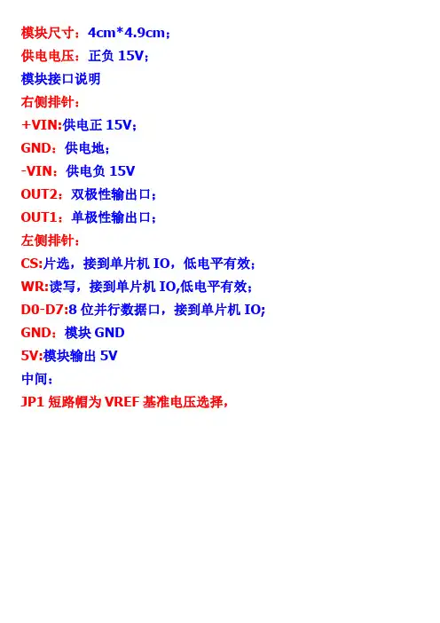
模块尺寸:4cm*4.9cm;供电电压:正负15V;模块接口说明右侧排针:+VIN:供电正15V;GND:供电地;-VIN:供电负15VOUT2:双极性输出口;OUT1:单极性输出口;左侧排针:CS:片选,接到单片机IO,低电平有效;WR:读写,接到单片机IO,低电平有效;D0-D7:8位并行数据口,接到单片机IO; GND:模块GND5V:模块输出5V中间:JP1短路帽为VREF基准电压选择,如果套上短路帽,模块的VREF为5V;如果取下短路帽,VREF可以自己外部输入自己要的基准电压;JP2单/双极性输出选择,短路帽套上为双极性输出(OUT2为双极性输出口);短路帽取下为单极性输出(OUT1为单极性输出口);本模块自带1路7805稳压电路,可以输出5V给单片机系统供电,接线图如下:如果单片机系统和AD模块要分开供电,接线图如下:模块电路图:单片机和DAC0832模块共用电源的接线实物图片:单片机模块图片:如果需要单片机模块、正负15V稳压模块、双12V变压器的,请点击以下链接另购:https:///item.htm?id=17269560671+-15V稳压模块链接:https:///item.htm?id=521413252575&mt=双12V变压器链接https:///item.htm?spm=a1z10.3-c.w4002-453401453.12.m4m4Tu&id=16400412775JP2取下时,模块为单极性输出,输出接口为OUT1,OUT1输出范围为-5V到0V;OUT1=-Vref*d/256 其中Vref为基准电压5V,d为单片机输出的数字量.JP2套上时,模块为双极性输出,输出接口为OUT2,OUT2输出范围为-5V到+5V;OUT2=Vref*d/128-Vref;其中Vref为基准电压5V,d为单片机输出的数字量。
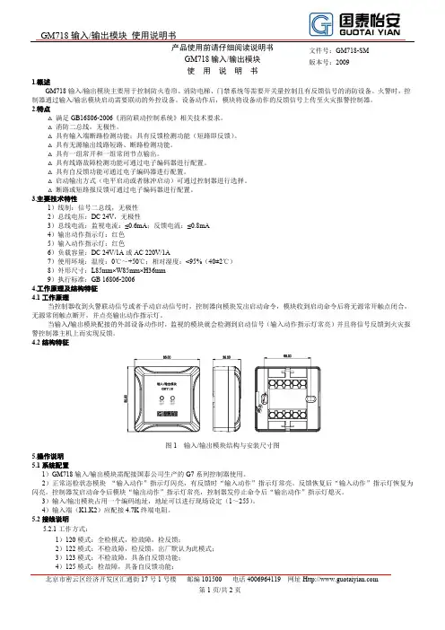
GM718输入/输出模块使用说明书北京市密云区经济开发区汇通街17号1号楼邮编101500 电话4006964119 网址第1页/共2页1.概述GM718输入/输出模块主要用于控制防火卷帘、消防电梯、门禁系统等需要开关量控制且有反馈信号的消防设备。
火警时,控制器通过输入/输出模块启动需要联动的外控设备。
设备动作后,模块将设备动作的反馈信号上传至火灾报警控制器。
2.特点△满足GB16806-2006《消防联动控制系统》相关技术要求。
△消防二总线,无极性。
△具有输入端断路检测功能;具有反馈检测功能(短路即反馈)。
△具有无源输出线路短路、断路检测功能。
△具有一组常开和一组常闭节点输出。
△具有线路故障检测功能可通过电子编码器进行配置。
△具有自反馈功能可通过电子编码器进行配置。
△启动输出方式(电平启动或者脉冲启动)可通过控制器进行选择。
△断路或短路报反馈可通过电子编码器进行配置。
3.主要技术特性1)线制:信号二总线,无极性2)总线电压:DC 24V,无极性3)总线电流:监视电流:≤0.6mA;反馈电流:≤0.8mA4)输出动作指示灯:红色5)输入动作指示灯:红色6)负载容量:DC 24V/1A或AC 220V/1A7)使用环境:温度:0℃~+50℃;相对湿度:<95%(40±2℃)8)外形尺寸:L85mm×W85mm×H36mm9)执行标准:GB 16806-20064.工作原理及结构特征4.1工作原理当控制器收到火警联动信号或者手动启动信号时,控制器向模块发出启动命令,模块收到启动命令后将无源常开触点闭合,无源常闭触点断开,并点亮输出动作指示灯。
当输入/输出模块配接的外部设备动作时,监视的模块就会检测到启动信号(输入动作指示灯常亮)并且将信号反馈到火灾报警控制器主机上而实现反馈。
4.2结构特征图1 输入/输出模块结构与安装尺寸图5.操作说明5.1系统配置1)GM718输入/输出模块需配接国泰公司生产的G7系列控制器使用。

PROFIBUS module for use with C440, S611, S811+ and as stand-alone I/OInstallationThe PROFIBUS T module is designed to be used in industrial applications and installed in accordance with this document.Mount the moduleThis PROFIBUS module is the stand-alone version. It can be used to interface a C440 motor protection OL relay, S611 or S811+ soft starters to PROFIBUS or can be used as a stand-aloneI/O module on PROFIBUS.The stand-alone design provides two optional mounting methods for the customer.• 35 mm DIN rail mounting• Panel mounting features 79x18 mm withtwo #10 screwsConnect the PROFIBUS adapterto PROFIBUSConnect the PROFIBUS cable to the PROFIBUS DB9 connector located on the side of the module. The connector has screws for positive retention to eliminate accidental unplugging.Connect 24 Vdc control power to the 5-position header.• The connector has screws for positive retention to eliminate accidental unplugging• Use one wire per terminal Set the PROFIBUS addressThe PROFIBUS address is set using the DIP switches located on the face of the module.The PROFIBUS address is binary with the major units numbered to the left of the switch on the side label. Adding up the major units set to ON determines the address of the module. Switches 1–7 are used for the address (shown below).T able 1. Switch addressDIP switch Value76463251648342211DIP switch 8 is used for special functions. Refer to the C441 PROFIBUS User Manual. Example: To set the address to 25, start fromthe switch mark 32 and set the switches toOFF (32), ON (16), ON (8), OFF (4), OFF (2), ON (1) (16+8+1=25).otee:N DIP switches are read only at power up.The PROFIBUS baud rate is set automatically using an auto baud technology; there is no need to set the baud rate.The GSD file is located on the Eaton website at .Figure 1. C441SS—120 Vac input specification2Instruction Leaflet IL042002ENEffective March 2015PROFIBUS module for use with C440, S611, S811+ and as stand-alone I/OEATON Figure 2. C441QS—24 Vdc input specificationInputsT able 2. 120 Vac input specificationsSpecificationValueNumber of inputs 4Voltage category 120 Vac Operating range 80–140 Vac Operating frequency 50/60 Hz Signal delay max.30 ms Off state voltage 0–30 Vac On state voltage 79–140 Vac On state current max.15 mASupply External supplyT able 3. 24 Vdc input specificationsSpecificationValueNumber of inputs 4Supply voltage 24 VdcTypeCurrent sinking On state voltage15 V – 30 Vdc Steady state current max.15 mA Off state voltage0–5 Vdc 24 Vdc source current limit 50 mA Isolation voltage 250 VacRelay outputsTwo relay outputs are provided, one Form A (NO) and one Form C (NO, NC).T able 4. Relay specificationsSpecification ValueNumber of contacts Two independent relays (one Form A, one Form C)Thermal contact5 A Rated insulation voltage 300 Vac Operating voltage240 VacOperating AC current (rated) 3 A at 120 Vac; 1.5 A at 240 Vac Operating DC current (rated)24 A at 110 Vdc, 0.1 A at 220 Vdc Minimum operating current 10 mA at 5 VdcResistive load rating 5 A at 240 Vac, 5 A at 30 Vdc Inductive loading 2 A at 240 Vac, 2 A at 30 VdcT able 5. Pilot duty relay requirementsSpecificationValuePilot duty ratingB300Thermal continuous test current5 AMaximum current (120 Vac)—make/break 30 A / 3 A Maximum current (240 Vac)—make/break 15 A / 1.5 AMaximum VA (volt-amperes)—make/break 3600 VA / 360 VA3Instruction Leaflet IL042002ENEffective March 2015PROFIBUS module for use with C440, S611, S811+ and as stand-alone I/O EATON PROFIBUS diagnosticsThe C441 PROFIBUS adapter provides the user with status information along with fault and warning data relevant to the operation of the attached base module. Fault and warninginformation is presented to the user through extended diagnostics. All fault information is sent to the Master as high priority diagnostic messages (ext. diag. bit set in diagnostic message). All warning information is sent as low priority diagnostic messages (ext diag. bit clear). Low priority diagnostic messages are issued as the fault condition clears.See the user manual for the attached base module’s diagnostic message bit definitions.T able 6. Environmental ratingsDescriptionRatingTransportation and storage Temperature –50 °C to +80 °C (–58 °F to +176 °F)Humidity 5–95% noncondensingOperatingTemperature –40 °C to +55 °C (–40 °F to +131 °F)Humidity 5–95% noncondensingAltitude Above 2000 meters (6600 feet) consult factory ShockIEC 68-2-2715 G any direction for 11 milliseconds Vibration IEC 68-2-610–150 Hz, 3 G, 0.3 mm maximum peak-to-peak Pollution degree Pollution IIIPower draw <30 mA steady state from 24 VdcDielectric withstandEquipment rating volts more than 50 V, potential volts AC 1000+2*V (max. marked voltage)T able 7. CertificationsDescriptionRatingAgency certificationscULus by UL T to UL 508, CSA T C22.2 No. 14 CE (Low Voltage Directive, EMC Directive), C-TICKRadiated and conducted emissions EN 55011 Class AElectrical/EMCESD immunity (IEC 61000-4-2)±8 kV air, ±4 kV contactRadiated immunity (IEC 61000-4-3)10 V/m 80–1000 MHz, 80% amplitude modulation at 1 kHz Fast transient (IEC 61000-4-4)±2 kV supply and IO ±1 kV communicationsSurge (IEC 61000-4-5)±2 kV line to PE and ±1 kV line-to-line RF conducted (IEC 61000-4-6)10 V, 0.15–100 MHz Magnetic field (IEC 61000-4-8)DNA Voltage dips (IEC 61000-4-11)DNA Protection degree (IEC 60947-1)IP20Certification of Compliance to the EU Directive 2011/65/EU (RoHS 2.0)YesReachYesPCB laminateManufactured by a UL Recognized (ZPMV2) printed wiring board manufacturer, which meets the requirements in UL 508, paras. 15.1, 15.3, 36.12, and 39.4(b). CB to be marked with Vendor UL-ID code, Vendor Date Code, material, flammability rating. Polarizedcomponents shall be marked so that polarity can be verified after assembly.T able 8. Module electrical requirementsDescriptionRatingVoltage range 18–30 VdcCurrent draw Approximately 50 mAotese:N For use with Eaton UL Listed Power Supply Catalog Nos. PSG240E or PSG240F24RM. Any UL Listed isolated power supply with a maximum of 30 Vdc output may be used, provided that a UL Listed or Recognized fuse rated no more than 3 A maximum be installed.Figure 3. 5-pin 24 Vdc power, RS-485 connectorModule LEDsT able 9. Input LEDs (I1–I4)DescriptionStatusLED color Green Input ON LED ON Input OFFLED OFFT able 10. Output LEDs (Q1 and Q2)DescriptionStatusLED colorYellow Relay (normally open) closed LED ON Relay (normally open) open LED OFFT able 11. PROFIBUS status LEDsDescriptionStatusPBUS BF SF Fault condition ON OFF OFF Everything OK ON ON OFF No communicationON Blinking OFF Communication, but not in data exchange ON ON ON Configuration not OKEaton1000 Eaton Boulevard Cleveland, OH 44122 United States © 2015 EatonAll Rights ReservedPrinted in USAPublication No. IL042002EN / Z16126 March 2015Eaton is a registered trademark.All other trademarks are propertyof their respective owners. PROFIBUS module for use with C440, S611, S811+ and as stand-alone I/OInstruction Leaflet IL042002EN Effective March 2015。
数字量输入/输出模块使用手册目录1. 输入模块 (1)1.1.16点12/24V直流输入模块(IDD40) (1)1.2.32点12/24V直流输入模块(IDD50) (3)1.3.16点数110V交流输入模块(IDA40) (5)1.4.16点数220V交流输入模块(IDA41) (7)2. 输出模块 (9)2.1.16点直流0.1A NPN输出模块(ODD40) (9)2.2.16点直流2A PNP输出模块(ODD42) (11)2.3.16点继电器输出模块(ODA40) (13)3. 电气和环境参数 (15)4. 模块安装与连接 (16)1. 输入模块1.1. 16 点12/24V直流输入模块 (IDD40)a.参数:b. 前面板:1)ACT 指示灯: 如果CPU模块正在对该模块进行服务时,ACT 指示灯亮,如果CPU模块停止服务超过0.2秒以上的时间,ACT指示灯熄灭。
2)输入显示LED灯:共有 16个LED灯用来显示输入状态。
对应的输入点工作时相应的指示灯亮。
3)接线端子:外部连线的接线端子是一个可拆卸的端子排,在模块出现故障时,用户不需要松开连线,只需要拆卸下端子排,更换故障模块即可。
c. 对应输入电路:1.2. 32点12/24V直流输入模块(IDD50)a. 参数:b. 前面板:1)ACT 指示灯: 如果CPU模块正在对该模块进行服务时,ACT 指示灯亮,如果CPU模块停止服务超过0.2秒以上的时间,ACT指示灯熄灭。
2)输入显示LED灯:共有 32个LED灯用来显示输入状态。
对应的输入点工作时相应的指示灯亮。
3)外部接线连接器: 37针连线D型连接器,需要与转接板ADD50配合使用,才能够方便连接。
c. 相应输入电路:1.3. 16点数110V交流输入模块 (IDA40)a.参数b.前面板:1)ACT 指示灯: 如果CPU正在对模块进行服务,ACT 指示灯会亮 ,如果CPU模块停止对模块服务的时间超过0.2秒时,ACT灯将会熄灭。
Eaton Logic ControllerELCM Combination AnalogInput/Output ModulesINSTRUCTION SHEET [Applicable Combination Analog Input/Output modules]ELCM-AN06AANNIL05004003E002-1301220-02The ELCM-AN06AANN combination analog input/output module supports 4 analog input channels (either voltage or current) and converts analog input signals into 16-bit digital data. For the analog outputs, theELCM-AN06AANN supports 2 channels of 16-bit digital data from the ELCM and converts this digital data into analog output signals (either voltage or current). You can access the data in the module by using the FROM/TO instructions, and read the average value or write the output value of channels directly by using the MOV instruction (Please refer to allocation of special registers D9900 ~ D9999).This instruction sheet provides only information on the electrical specification, general functions, installation and wiring. It should be read and understood before attempting to install or use the module.Further information can be found in the “ELC Programming Manual” and “ELC Special Modules Operation Manual”.This analog I/O module is a part of an OPEN TYPE control system. The ELCM should be kept in an enclosure away from airborne dust, humidity, electric shock risk and vibration. Your application may require that the enclosure be locked to prevent non-maintenance staff from operating the controller (e.g. key or specific tools that are required for opening the enclosure) in cases where danger and damage to equipment orpersonnel may occur. Do NOT touch the terminals while power isapplied.Do not connect AC power to any of the input terminals, as it will damage the modules. Check all wiring prior to power up.Ensure the ground terminal is correctly grounded in order to prevent electromagnetic interference.This manual is subject to change without notice.Product Profile & DimensionUnit: mm External WiringInput: Active-typeInput: Passive-typeOutputrecorder,scale valve...Terminal of recorder, scale valve...Note 1: Please isolate analog input signals from power wiring.Note 2: When the XA module analog input is connected to current signals, make sure youshort-circuit "V+” and “I+” terminals. Note 3: If the ripples at the loaded input terminal are large enough to cause noise interferenceon the wiring, connect a 0.1 ~ 0.47μF 25V capacitor as shown. Note 4: Please isolate analog output signals from power wiringNote 5: If the ripples at the loaded output terminal are large enough to cause noise interferenceon the wiring, connect a 0.1 ~0.47μF 25V capacitor as shown. Note 6: Please connect the terminal on both the power supply and the combination analogmodule to a suitable system earth groundI /O Terminal LayoutNote: Use 12-28 AWG single-core bare wire or multi-core (stranded) wire for the I/O wiring.The ELCM terminal screws should be tightened to 4.75kg-cm (4.12 in-lbs) and please use60/75°C copper conductor only.Electrical SpecificationsFunctions SpecificationsControl Register※CR#43: Error status value. See the table below:Explanation on Special Registers D9900~D9999 When ELCM-PH/PA is connected with modules, registers D9900~D9999 will be reserved for storing values from those modules. You can apply the MOV instruction to access values in D9900~D99999.When ELCM-PH/ELCM-PA controllers use ELCM-AN06AANN combination analog input/output modules, special registers are configured as shown below:Note 1: D9900 ~ D9999 are average input values of CH1 ~ CH4 and the average times is K1 ~ K100. When the average times is set to K1, the values displayed in D9900 ~ D9999 arecurrent values. You can use: 1. ELCM_AIO Configuration Function of ELCSoft or 2. FROM/TO instructions (CR#8~CR#11) to set the average times as K1.Adjust A/D Conversion CurveUsers can adjust the conversion curves according to the actual needs by changing the Offset value (CR#28 ~ CR#31) and Gain value (CR#34 ~ CR#37).Gain: The corresponding voltage/current input value when the digital output value = 16,000.Offset: The corresponding voltage/current input value when the digital output value = 0.Equation for voltage input Mode0 / Mode2: 0.3125mV = 20V/64,000 = 10V/32,000()Offset Gain Offset V V X Y -⎪⎪⎭⎫ ⎝⎛-⨯⨯=320001016000)()(Y=Digital output, X=Voltage input Equation for voltage input Mode1 / Mode3: 0.15625mV = 10V/64,000 =()Offset Gain Offset V V X Y -⎪⎪⎭⎫⎝⎛-⨯⨯=32000516000)()(Y=Digital output,X=Voltage inputEquation for current input Mode4 / Mode5: 0.625μA = 40mA/64,000 = 20mA/32,000()Offset Gain Offset mA mA X Y -⎪⎪⎭⎫ ⎝⎛-⨯⨯=320002016000)()(Y=Digital output, X=Current input Equation for current input Mode6: 0.5μA = 16mA/32,000Adopt the equation of current input mode4/mode5, substitute Gain for19,200 (12mA) and Offset for 6,400 (4mA)()6400192006400320002016000-⎪⎪⎭⎫ ⎝⎛-⨯⨯=)()(mA mA X YY=Digital output, X=Current inputMode 0:Mode 1:Mode 2:Mode 3:Digital outputDigital outputMode 4:Mode 5:Mode 6:Adjust D/A Conversion CurveUsers can adjust the conversion curves according to the actual needs by changing the Offset value (CR#32 ~ CR#33) and Gain value (CR#38 ~ CR#39).Gain: The corresponding voltage/current output value when the digital input value = 16,000.Offset: The corresponding voltage/current output value when the digital input value = 0.Equation for voltage output Mode0: 0.3125mV = 20V/64,000()()⎪⎭⎫ ⎝⎛⨯⎥⎦⎤⎢⎣⎡+-⨯=32000)(1016000V Offset Offset Gain X V YY=Voltage output, X=Digital input Equation for current output Mode1: 0.625μA = 20mA/32,000()()⎪⎭⎫ ⎝⎛⨯⎥⎦⎤⎢⎣⎡+-⨯=32000)(2016000mA Offset Offset Gain X mA YY=Current output, X=Digital input Equation for current output Mode2: 0.5μA = 16mA/32,000 Adopt the equation of current output Mode 1, substitute Gain for19,200(12mA) and Offset for 6,400(4mA)()()⎪⎭⎫ ⎝⎛⨯⎥⎦⎤⎢⎣⎡+-⨯=32000)(20640016000640019200mA X mA YY=Current output, X=Digital inputmode 0:mode 1:mode 2:。
SpecificationsSUPDM56HW - UPS Accessory - Hardwire PDU ModuleMODEL NUMBER: SUPDM56HWDescriptionThe SUPDM56HW hardwire input/output PDU module converts compatible SmartOnline Hot-Swappable Modular UPS Systems (models SU5000RT4U and SU6000RT4U) to a totally hardwired solution. Easy quick-connect terminal block allows installation of hardwire distribution module in minutes. Can accept input voltages of 120/208 or 120/240 VAC split-phase power. Detachable hardwire module allows for effortless UPS maintenance without the need to power down connected loads and re-wire input/output connections.FeaturesThe SUPDM56HW hardwire input/output PDU module converts compatible SmartOnline Hot-Swappable Modular UPS Systems (models SU5000RT4U and SU6000RT4U) to a totally hardwired solutionqEasy quick-connect terminal block allows installation of hardwire distribution module in minutes q Can accept input voltages of 120/208 or 120/240 VAC split-phase powerq Detachable hardwire module allows for effortless UPS maintenance without the need to power down connected loads and re-wire input/output connectionsqHighlightsConverts compatibleSmartOnline Hot-Swappable Modular UPS systems to hardwire input and output qFor use with input voltages of 120/208 or 120/240 VAC split-phase powerqConvenient quick-disconnect terminal block allows installation in minutesqSystem RequirementsUse with SU5000RT4U and SU6000RT4U split-phase SmartOnline Hot-Swappable Modular UPS SystemsqPackage IncludesSUPDM56HW hardwire PDU q Mounting Hardware q Owner's Manualq© 2023 Eaton. All Rights Reserved. Eaton is a registered trademark. All other trademarks are the property of their respective owners.。
松江消防模块和系统调试的详解松江控制模块及系统调试随着社会经济的发展和进步,现代化智能建筑的增多,消防联动控制系统在智能建筑中的楼宇自动化系统(BAS)起着重要作用。
联动控制模块是消防控制系统实现对建筑内消防设备、电梯设备、照明、空调、给排水等安全设备联动控制的重要单元。
建筑内一旦发生火灾消防探测设备把探测信号传送到消防控制中心,确认火灾发生后,消防控制中心要通过模块控制启动防排烟系统设备、消防电梯降到首层、防火门(防火卷帘)关闭、警铃及声光报警器启动、消火栓、自动喷淋系统设备启停等。
一、按信号的输入输出方式分为输入模块、单输入单输出模块、双输入双输出模块、输出模块。
1、输入模块:在消防系统中适时接受处理现场各种报警探测装置发出的无源报警信号,并实现把信号向火灾报警控制器传输。
可接收可燃气体探测器、紫外线火焰探测器、水流指示器、压力开关等无源接点的动作信号。
消防控制中心接到设备动作信号后,根据模块的编码地址可快速判断现场报警设备的地址,确认火灾是否发生。
输入模块用于接收消防联动设备输入的常开或常闭开关量信号,并将联动信息传回火灾报警控制器(联动型)。
主要用于配接现场各种主动型设备如水流指示器、压力开关、位置开关、信号阀及能够送回开关信号的外部联动设备等。
这些设备动作后,输出的动作信号可由模块通过信号二总线送入火灾报警控制器,产生报警,并可通过火灾报警控制器来联动其它相关设备动作。
输入模块上有两对有效接点,其中一对接点与二总线连接,另一对与现场设备的无源接点连接。
HJ-1750型中继模块用于接收消防联动设备输入的常开或常闭开关量信号,并将联动信息传回火灾报警控制器(联动型)。
主要用于配接现场各种主动型设备如水流指示器、压力开关、位置开关、信号阀、湿式报警阀及能够送回开关信号的外部联动设备等。
这些设备动作后,输出的动作信号可由模块通过信号二总线送入火灾报警控制器;产生动作报警信号,并可通过火灾报警控制器来联动其它相关设备动作,应与无源触点连接。
硬件产品手册北京和利时系统工程股份有限公司 6/28/2006目录1基本说明 (1)1.1 简介 (1)1.2 组成 (1)2原理说明 (2)3使用说明 (3)3.1端子接线说明 (3)3.2有源单线制接法 (4)3.3有源两线制接法 (4)3.4无源两线制接法 (5)3.5 状态指示灯说明 (5)4安装与拆卸 (6)4.1安装 (6)4.2拆卸 (6)5相关产品信息 (7)6技术指标 (7)HollySys端子模块FM136十六路交流220V开关量输入端子模块1基本说明1.1 简介FM136端子模块是16路交流220V开关量输入模块,将现场以220V AC为查询电源的16路开关量输入信号转换成以24VDC为查询电源的晶体管开关量信号,并通过40针扁平电缆将信号送入FM161系列DI模块,实现对220V AC/50Hz的交流开入信号的处理。
FM136模块在220V交流输入端子的L端加入了保险管,对模块进行限流保护。
从交流接线端子输入的220VAC查询电压,全部通道最大输入电流为250mA。
1.2 组成FM136模块主要由接线端子、LED灯、跳线器和40针牛角连接器构成,如图1-1所示。
LED灯D1~D16分别对应第1通道~第16通道;跳线器JP1~JP16分别对应第1通道~第16通道;接线端子J2~J9对应第1通道~第8通道, J11~J18对应第9通道~第16通道;图1-1 FM136模块外观图HollySys 1HollySys 2现场220V AC 交流开入信号由端子接入FM136端子模块后,经分压、整流、滤波、光耦转换成24VDC 晶体管开关量信号,通过FM131-C-A 底座送入FM161系列开关量信号输入模块,从而实现对查询电源为交流220V AC 的开关量信号的采集与处理。
FM136端子模块的电气原理接口框图如图2-1所示:图2-1 FM136端子模块的电气原理接口图3.1端子接线说明现场信号接到FM136端子模块的接线端子J2~J18上,其中J10为220V AC接线端子。