(整理)卷帘门机变频器说明书.
- 格式:doc
- 大小:1.67 MB
- 文档页数:14
nais门机变频器说明书
调试方法:
1、确定电机的定位角。
进入菜单332按确定键。
出厂前已经定位好,新门机不需要定位。
如果确实需要定位,必须保证电机空载运行。
2、确定开、关门方向。
进入菜单311,按确定键。
门应往开门方向缓慢运动。
按CLEAR 键,门停止。
如果方向相反(往关门方向运动),则进入菜单3311,修改[Rotatedir1/0]。
修改方法为:如果[Rotatedir1/0]的当前值为1,则改为0;如果当前值为0,则改为1。
修改后再次确认开、关门方向。
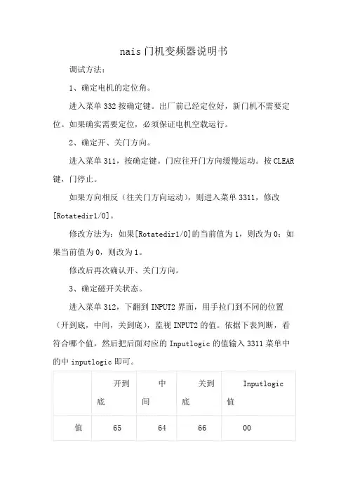
3、确定磁开关状态。
进入菜单312,下翻到INPUT2界面,用手拉门到不同的位置(开到底,中间,关到底),监视INPUT2的值。
依据下表判断,看符合哪个值,然后把后面对应的Inputlogic的值输入3311菜单中的中inputlogic即可。
4、自学习。
进入菜单334,按确定键。
耐心等待,直到自学习完成。
至此,调试完成,门机能较好的运行。
把门机的控制模式改为演示运行(Runcomdsource=2),然后进入菜单313按确认键,使门机演示运行。
然后观察门机,根据门机运动状况做适当的调整。
![电梯门机专用变频器说明书V2[1].06__010111](https://uimg.taocdn.com/349ad8d97f1922791688e887.webp)
目录1 前言 (1)2 安全使用注意事项 (2)3 键盘面板操作 (3)4 快速调试 (4)4. 1 使用机械限位开关 (4)4.2 使用绝对值编码器 (5)4.3使用增量式编码器 (6)5 功能参数说明 (7)5.1基础功能 (7)5.2速度调节 (8)5.3编码器模式 (9)5.4运行时间及保护 (10)5.5 V/F 曲线、开关量输出 (11)5.6通讯 (12)5.7通用型变频器模式 (12)6 故障信息及排除........................................... (13)7 电气接线图................................................... 1 51 前言感谢您选用多功能、高性能的研和C102双核(双CPU快速门控制系统。
本产品性能稳定、控制参数界面友好、功能强大、方便调试和维护。
可配套控制PVC快速卷帘门、堆积门、硬质快卷门等工业门类。
产品特点:1 、可选择机械限位开关、绝对值编码器、增量式编码器控制模式。
2、内置卷帘门控制的核心芯片;双CPU。
3、体积更小,功能更强;380V/2.2KW-220V/1.5KW统一安装尺寸。
4、具备双门互锁且自动开门、风帘机控制、门上升到位、门下降到位、手动不联锁/ 自动联锁功能。
5、具备编码器控制模式下全开/半开功能、拉绳开关功能。
6、可直接显示编码器位置数据。
7、恢复出厂值、密码保护、电机双重保护功能。
8、设定及故障均有提示或报警代码,方便调试及维护。
9、全部输入信号均可参数实时监控。
10、变频器、PLC合二为一,高度集成。
2 安全使用注意事项1、实施配线前,请务必关闭电源。
2、切断交流电源后,指示灯未熄灭前,表示变频器内部仍有高压,十分危险,请勿触摸内部电路及零部件。
3、运转时,请勿检查电路板上零部件及信号。
4、请勿自行拆装更改变频器内部连接线、线路及零部件。
5、所选用电源电压必须与变频器输入电压规格相同。
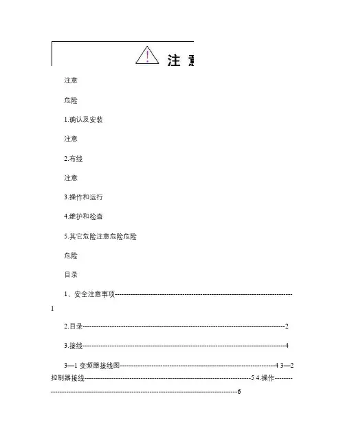
1.确认及安装注 意2.布线注意注意危险3.操作和运行4.维护和检查5.其它危险注意危险危险危险目录1、安全注意事项-------------------------------------------------------------------------------1 2.目录------------------------------------------------------------------------------------------2 3.接线------------------------------------------------------------------------------------------4 3—1 变频器接线图---------------------------------------------------------------------4 3—2 控制器接线--------------------------------------------------------------------------5 4.操作-------------------------------------------------------------------------------------------6 4—1 各按键功能及指示-----------------------------------------------------------------6 4—2 基本操作-----------------------------------------------------------------------------7 4—3 系统参数-----------------------------------------------------------------------------7 5.其它参数------------------------------------------------------------------------------------10 5—1 相关技术参数-----------------------------------------------------------------------10 5—2 电气参数-----------------------------------------------------------------------------10 6.调试说明------------------------------------------------------------------------------------11 6-1两个关键词的解释---------------------------------------------------------------------11 6-2门机控制器调试的具体步骤---------------------------------------------------------11 7.故障处理-------------------------------------------------------------------------------------13 8、其它---------------------------------------------------------------------------------------------138—1 废物处理------------------------------------------------------------------------------13 8—2 咨询修理------------------------------------------------------------------------------13 9、附页---------------------------------------------------------------------------------------------14附页1:门机安装注意事项-----------------------------------------------------------------14 附页2:双折门机直梁安装示意图--------------------------------------------------------15 附页3;轿顶安装示意图--------------------------------------------------------------------161-12、外观和各部分的名称3-1 控制器接线注:P3开关门指令输入,要求是开关量无源输入。
138172801_EN_0614Roller shutter drive RolTop /D+ 868 1Operating and installation instructionsPlease keep these operating instructions for later use, to be available throughout the life of the product! The German manual is the original version.All other documents represent the language translations of the original text.All rights in the case of a patent, utility model or ornamental design registration are reserved.2 General for instructionsThe content structure is based on the life cycles of the elec-tric motor drive (hereinafter referred to as "Product"). The manufacturer reserves the right to make changes to the Speci fi cations stated in these Operating Instructions at any time. These may, in individual cases, be different from the respective product version, however the functional information will not undergo signi fi cant changes or become invalid. The current version of the Speci fi cations may be requested from the manufacturer at any time. No claims may be asserted against the manufacturer as a result of the preceding sentence. Deviations from text or picture state-ments are possible and depend on the technical develop-ment, features, and accessories of the products. Deviating information on special versions will be explained by themanufacturer in the sales documentation. Other information shall remain unaffected by these provisions.2.1 Standards and DirectivesDuring the design process, the basic health and safety requirements of the applicable laws, Standards and Direc-tives were complied with. The safety is con fi rmed by the declaration of conformity (see "Declaration of Conformity"). All safety information in these Operating Instructions refer to the laws and regulations currently applicable in Germany. All instructions in the Operating Instructions shall be ob-served without limitation and at any time. Beside the safety instructions contained in these Operating Instructions, the provisions for accident prevention, environmental protection and occupational safety, which are applicable for the op-erating site, must be observed. Provisions and Standards for the safety rating can be found in the EC Declaration of Conformity2.2 Intended useThe product is intended for use in façade engineering todrive electrically powered roller shutters.The determining factor for the drive is the elero drive com-putation program (/de;service;antriebsberechnungsprogramm.htm). Further fi elds of application have to be arranged with the manufacturer, elero GmbH Antriebstechnik (see Address). The operator will be solely responsible for damages result-ing from improper use of the product. The manufacturer cannot be held liable for personal or material damages caused by misuse or procedural errors, and by improper operation and commissioning.The product may be operated only by trained and author-ized personnel under observance of all safety.Table Of Contents 1Operating and installation instructions12 General for instructions 12.1 Standards and Directives 12.2 Intended use 12.3 Foreseeable misuse 22.4 Warranty and liability22.5Customer service of the manufacturer23 Safety 23.1 General safety instructions 23.2 Layout of the safety guidelines 24Product description35 Assembly 35.1 Mechanical fastening 45.2Electrical connection45.3 Connection example,RolTop /D+ 868 230 V/50 Hz 45.4Initial operation55.4.1 Connection for cable assembly 55.4.2 Connection for radio(transmission operation)55.4.3 Changing / Deleting the end positions 55.4.4 Programme or delete further curtainpositions 55.5 Programming the transmitter 55.6Programming (additional) transmitter56 Troubleshooting 67 Maintenance 68 Repair 69 Manufacturer's address 610 Disassembly and disposal611 Notes on the EC declaration of conformity 712Technical data and dimensions73 Safety3.1General safety instructionsThe instructions on safety that must be observed under all circumstances are included in the separately enclosed lea fl et on safety instructions (13 820 0001).3.2 Layout of the safety guidelinesThe safety instructions in this document are identi fi ed by hazard signs and safety symbols and are designed accord-ing to the SAFE principle. They contain information on the nature and source of the danger of possible consequences and to prevent the danger.The following table de fi nes the representation and descrip-tion of hazard levels with possible personal injury, as used in this manual.Fig. 1 Notation of personal injuryThe following table describes the icons used in these op-erating instructions that are used for imaging of the dan-gerous situation in connection with the symbol of the threat level.Fig. 2 Notation-speci fi c hazardThe following table de fi nes the representation used in the operating instructions and description of situations where damage can occur to the product or refers to important facts, conditions, tips and information.2 | EN © elero GmbHStandards and Directives| SafetyOnly if used according to the speci fi cations of these operat-ing and installation instructions for the safe and proper use and safe operation of the product are guaranteed.Only use radio receivers with equipment and units approved by the manufacturer. The operator does not bene fi t from any protection whatsoever against interference from other remote control equipment and terminal equipment (e.g. also from radio equipment which is correctly operated in the same frequency range). Please note that radio systems must not be operated in areas with an increased risk ofinterference (e.g. hospitals, airports,....). The radio control is only permitted for devices and units with which a functional interference in hand-held/wall transmitters or receiversposes no danger for persons, animals or materials or where this risk is covered by other safety appliances.Intended use includes the observance and compliance with all safety instructions with regards to this operating manual and all applicable regulations, and professional associations of applicable laws for environmental protection. Intended use includes the observance of prescribed operating rules in these operating and installation instructions.2.3 Foreseeable misuseA use which deviates from the intended use stated by themanufacturer, elero GmbH Antriebstechnik (see "Address"), is deemed as foreseeable misuse.2.4 Warranty and liabilityPrincipally, the General Terms and Conditions of the man-ufacturer, elero GmbH Antriebstechnik (see "Address"), apply. The terms and conditions are part of the sales documents and handed over to the operator upon deliv-ery. Liability claims for personal or material damages are excluded when they can be attributed to one or more of the following causes:• Opening of the product by the customer • Unintended use of the product• Improper installation, commissioning, or operation of the product • Structural modi fi cations to the product without the written consent of the manufacturer • Operation of the product with improperly installed con-nections, defective safety devices or improperly installed safeguards • Non-observance of the safety provisions and instructions of these Operating Instructions • Non-compliance with the technical data2.5 Customer service of the manufacturerThe product should only be repaired by the manufacturer in case of a failure. The address for sending to customer service, see the chapter "Address".If you have not purchased the product directly from elero, please contact the supplier of the product.Fig. 3 Notation of property damage as well as additionalinformation The following example represents the basic structure of a safety warning:Type and source of dangerExplanation of the type and source of the danger ►Measures to prevent the danger.4 Product descriptionThe RolTop /D + 868 is a radio-controlled electromechanical tubular motor drive. It performs parallel axial movements. ❑Commissioning of the RolTop /D + 868 does not require any elero assembly cable. The elero assembly cableserves only for the deletion of the end positions and/or for restoring the delivery status if necessary. Commissioning of the RolTop /D+ 868 for setting of different functions takes place using the elero assembly cable or an elero radio transmitter. ❑The RolTop /D + 868 needs fi xed stops at the top and bottom. The use of rigid shaft connectors and plugs stop or angle strips or covert attacks is a prerequisite. There is a relief function at both stop points. ❑If an obstacle is recognised, type S will perform a relief by approx. 2 motor turns; type M will perform approx. 1 motor turn (hanging protection with running free). ❑When the same force deactivation has taken place three times in sequence at the top and bottom, the end posi-tions have been set (self-learning). ❑After obstacle recognition in the area of the end positions, they are immediately corrected down by up to 1 motor turn (360°) if, e.g., a window sill has been installed sub-sequently.5 AssemblyPersonal injury from hot surfaces.Drive heats up during operation, the drive housing can be hot. Possible burning of the skin.►Wear personal protective equipment (gloves).Triggered by a possible material errors may occur orimpact shock and injury due to a gearbox break, bud break or a clutch defect.►Suitable materials are to be used for the construction as well as perform a sampling inspection by double load test according to DIN EN 60335-2-97.Risk of injury due to impact or shock caused by not prop-erly mounted or latched motor bearings. Hazards caused by insufficient stability or stability and stored energy (grav-ity).►Selection of engine bearing torque speci fi cations. ►Drive must be backed up with all attached backup devic-es. ►Check for proper latching on engine mounts and correct tightening torques.Danger of injury due to electric current. Electric shock possible.►Electrical work can only be performed by an authorizedelectrician. Danger of injury due to electric current.Hazardous possibly by parts that have become live in the error state.►Electrical connection is described in the operating and installation instructions including cable bushing.Risk of injury due to malfunctions due to improper installa-tion.Driven by winds and possibly destroyed parts of the appli-cation.►For safe operation, the end positions must be set / pro-grammed. ►Training program of the manufacturer for specialist com-panies.Loss of power supply, termination of machine parts and other malfunctions.►For safe operation, no false mount must be made and the end position settings must be carried out during commis-sioning. Damage to the RolTop /D + 868 due to moisture penetra-tion►For devices with protection class IP44, the ends of all cables or connectors must be protected against theingress of moisture. This measure must be implemented immediately after removal of the RolTop /D+ 868 from the original packaging. ►The drive must be installed in a position in which it is not sprinkled.ImportantIn the delivery status (factory setting), the RolTop /D + 868 in commissioning mode.►You have to set the end positions (see chapter 5.6). This is done self-learning (torque-dependent). Best utilisation of the radio signal.►Place the aerial as freely as possible; in case of bad reception, move the aerial. ►Do not kink, shorten or extend the aerial.►Do not undercut the minimum distance of 15 cm between two radio drives.© elero GmbH EN | 3Product description | Assembly►For units with protection class IP 44, the customer con-nection of the cable ends or connector (cable bushing)must also be carried out in accordance with protection class IP 44. Damage to the Venetian blind from incorrect running direc-tion►The assignment of the running direction UP/DOWN with an elero radio transmitter must be reviewed after teach-ing. Adjustment of the end position at the drive.►Any adjustment of the end positions that occurs indicates an electrical connection error. Readjustment of the end positions is not suf fi cient in this case, since the endpositions are adjusted often. In this case, the drive needs to be replaced and the cause removed.ImportantAll applicable standards and provisions must be observedfor the electrical installation.When connecting the drive to a control, the operating instructions of the control must be observed.For electric connection no transmission and retransmission of the access line or connector is required as a rule. Depending on the mounting plate and/or adapter plateused it is necessary in particular with the RolTop /D+ 868 to remove this screwed plate before a cable exchange. Connection only in free of tension status, in addition drive line without tension1 Using a suitable screwdriver, press out the lock of the device connector to the line.2 Disconnect the plug.3 Insert connector until the latch engages.5.3 Connection example,RolTop /D+ 868 230 V/50 HzN PEL1swbr bl gr/ge 4 | EN © elero GmbHMechanical fasteningElectrical connection | Programming the end positions9 Manufacturer'saddress elero GmbHAntriebstechnik Linsenhofer Str. 65 72660 Beuren Deutschland / Germany Phone: +49 7025 13-01 Fax: +49 7025 13-212 *************Please visit our website if you require a contact outsideGermany.10 Disassembly and disposalDispose of the packaging according to current regulations.Dispose the product after previous use in accordance withapplicable regulations. Disposal is partially subject to stat-utory provisions. The goods to be disposed of must only bedelivered to authorised acceptance points.Environmental informationNo unnecessary packaging was used. The packaging canbe easily divided into three material types: Cardboard (box),Styrofoam (padding) and polyethylene (bag, foam materialprotective foil).The device is made up of materials that can be reused if itis disassembled by a specialist operation. Please observethe local provisions on disposal of packaging material andold devices.Always expect additional danger that does not occur inoperation during disassembly.Danger of injury due to electric current.Electric shock possible.►Physically disconnect power supply lines and dischargecharged energy storage. Wait for at least 5 minutes afterdeactivation for the motor to cool down and the capaci-tors to lose their voltage.►Use suitable, tested and stable climbing aids when per-forming disassembly work above body height.►All work at the electrical system must only be performedby the staff described in the chapter "Safety instructionsfor electrical installation".ScrappingDuring the scrapping of the product, the international,national and regional-specifi c laws and regulations are to becomplied with.Please make sure to consider material recyclability, ease ofdismantling, and separability of materials and componentsas well as environmental and health hazards during recy-cling and disposal.Environmental damage at incorrect disposal►Electronic scrap and electronic components are subjectto the hazardous waste rules and must only be disposedof by approved specialist operation.►Groups of materials such as plastics and metals of vari-ous kinds are sorted for recycling and disposal process.Dispose electrical and electronic componentsDisposal and recycling of electric and electronic compo-nents must comply with the applicable national laws andregulations.6 | EN © elero GmbHTeach in transmitter | TroubleshootingStop bidirectional radio teaching mode:Keep the STOP button pushed for at least 6 seconds untilthe status display lights up (depending on transmitter).6 TroubleshootingFig. 8 Troubleshooting for the RolTop /D+ 8687 MaintenanceThe RolTop /D + 868 is maintenance-free.8 RepairPlease contact your dealer if you have any questions.Please always provide the following information:• Item number and name on the type plate• Type of fault• Previous and unusual events• Surrounding circumstances• Own assumptionTechnical data11 Notes on the EC declaration ofconformityelero GmbH hereby declares that the pipe drive RolTop/D+ 868 complies with the basic prerequisites and the otherrelevant provisions of the EC directives. The completedeclaration of conformity can be found in the download areaof our website.12 Technical data and dimensions© elero GmbH EN | 7We reserve the right to make technical changes.elero GmbH Antriebstechnik Linsenhofer Straße 65 D-72660 Beuren *************Phone: +49 7025 13-01 Fax: +49 7025 13-212。
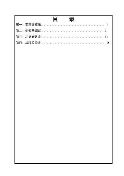
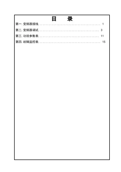
目录第一、变频器接线 (1)第二、变频器调试 (3)第三、功能参数表 (11)第四、故障监控表 (15)日期:2007-05-18版本:第A版第二部分变频器调试修改:第0次第二、变频器调试操纵说明:为使门机完成自学习及正常运行,需适当改变一些参数值.修改参数的基本操纵如下:按“MODE”键会循环出现Fr,dr,n及P菜单,d菜单在P菜单后.进入P菜单后,按“▲”键,P菜单的参数项增加,达到P79后再按“▲”键就进入d菜单,按“▼”键可返回P菜单.进入指定菜单项,按“SET”键,再根据情况按“▲”或“▼”键,可改变该参数值,改完后按“SET”键参数值就修改完毕并返回该参数的下一项.注:P08和P09的值不克不及在线修改,须按下“STOP”键后方可修改.一:磁开关节制方式1检查线路,请参考图1-2接线图仔细检查变频器信号是否接错.2 确认电机正反转:2.1 按“MODE”键出现Fr菜单,设置Fr为3.2.2 进入P级菜单,设置P08=1,P09=0.然后按“MODE”键返回原始界面(OOO).2.3 先按▲,再按RUN,确认门在开动作;然后按下▼,再按RUN确认门在关动作.若门不动作或动作太缓慢,需按“STOP”键返回原始界面(OOO),再进入P级菜单把P05的值增大到20左右(力矩提升).若门运行方向相反,则改变电机U,V,W中的任意两相.2.4 确认电机转向正确后按“STOP”键,返回原始界面(OOO).3 形式设定:请参考表2-1,表2-2.4进入P级菜单,设置P43的值为3(有编码器)、27(无编码器).5 运行:设置P09的值为5,然后按“MODE”键返回原始界面(OOO).先按▲,再按RUN或先按▼,再按RUN;门机将自动检测磁开关的位置,并自动运行.6 运行曲线调整:参数设置完毕后,门机在开关门时已经有了一定的运行曲线,如果运行曲线不敷平滑,则可以对运行曲线停止微调.开门调节曲线见图2-1,关门调节曲线见图2-2,曲线调节方法见图2-5.P级菜单和d级菜单中每一个的含义见表3-1、表3-2.日期:2007-05-18版本:第A版第二部分变频器调试修改:第0次图2-1无编码器方式速度曲线(开门运行曲线)1、以力矩提升为P05,加减速时间d28,频率d15启动,再以加减速时间d29,方针值为d16进入开门起始低速运行;2、颠末时间d47后,开端以加减速时间d30,方针值为d17进入开门高速运行.高速段频率一般设置的d17=d19;3、当门运行到开门变速开关位置时,通过延时d48后,开端以加减速时间d33,方针值为d20进入开门低速运行;4、当门运行到开门到位开关位置时,门以坚持频率d21,坚持电流d40进入开门到位力矩坚持.注意:1、开门到位坚持频率为d21,坚持电流d40,坚持时间d42,范围为0.1~999(sec),当设置为0时,则长期坚持.2、高速段频率一般设置为一段即设置参数d17=d19,此时d17与d19之间的加减速d32不起作用.3、若低速段开门力矩较小,可以适当调大P05.注意过大P05值能够会引起过流呵护.日期:2007-05-18版本:第A版第二部分变频器调试修改:第0次图2-2无编码器方式速度曲线(关门运行曲线)1、以力矩提升为P05,加减速时间d34,频率d22启动,再以加减速时间d35,方针值为d23进入关门起始低速运行;2、颠末时间d49后,开端以加减速时间d36,方针值为d24进入关门高速运行.高速段频率一般设置的d24=d26;3、当门运行到关门变速开关位置时,通过延时d50后,开端以加减速时间d39,方针值为d27进入关门低速运行;4、当门运行到关门到位开关位置时,门以坚持频率d14,坚持电流d41进入关门到位力矩坚持.注意:1、关门到位坚持频率为d14,坚持电流d41,坚持时间d42,范围为0.1~999(sec),当设置为0时,则长期坚持.4、高速段频率一般设置为一段即设置参数d24=d26,此时d24与d26之间的加减速d32不起作用.5、若低速段关门力矩较小,可以适当调大P05.注意过大P05值能够会引起过流呵护.日期:2007-05-18版本:第A版第二部分变频器调试修改:第0次图2-3编码器方式速度曲线(关门运行曲线)1、以力矩提升为P05,加减速时间d34,频率d22启动,进入关门起始低速运行;2、当门位置脉冲≥d09*门宽后,开端以加减速时间d35,方针值为d23进入关门高速运行.高速段频率一般设置的d23=d24=d25=d26;3、当门位置脉冲≥d13*门宽时,门机以加减速时间d39,方针值为d27进入关门低速运行;4、当门位置脉冲≥d02*门宽时,门以坚持频率d14,坚持电流d41进入关门到位力矩坚持.注意:1、关门高速段一般设置d23=d24=d25=d26,对应时间参数d36/d37/d38不起作用.2、需要情况下,可不设置关门起始低速段,即设置d22=d23,同时,应增大参数值d34(d34=1.2),减小参数d09(d09=75),以包管关门运行平稳.3、在改变门位置点参数时,要包管数值的大小(比方d13<d12).4、关门到位坚持频率为d14,坚持电流为d41.坚持时间为d42,范围为0.1~999,当设置为0时,则长期坚持.5、关门过程中当有卡门阻力大于设定值(过载)时,会执行开门.设定参数为:p64(低速区)、p65(高速区)、高低速区的分界频率参数 p66.参数p64、p65设定值越大,执行开门的卡门阻力越小.卡门阻力断定时间为p67.6、若低速段关门力矩较小,可以适当调大P05.注意过大P05值能够会引起过流呵护.日期:2007-05-18版本:第A版第二部分变频器调试修改:第0次图2-4 编码器方式速度曲线(开门运行曲线)1、以力矩提升为P05,加减速时间d28,频率d15启动,进入开门起始低速运行;2、当门位置脉冲≥d03*门宽后,开端以加减速时间d29,方针值为d16进入开门高速运行.高速段频率一般设置的d16=d17=d18=d19;3、当门位置脉冲≥d07*门宽时,门机以加减速时间d33,方针值为d20进入开门低速运行;4、当门位置脉冲≥d08*门宽时,门以坚持频率d21,坚持电流d40进入开门到位力矩坚持.注意:1、开门高速段一般设置d16=d17=d18=d19,对应时间参数d31/d32/d33不起作用.2、在改变门位置点参数时,要包管数值的大小(比方d06<d07).3、开门到位坚持频率为d21,坚持电流为d40.坚持时间为d42,范围为0.1~999,当设置为0时,则长期坚持.4、若低速段关门力矩较小,可以适当调大P05.注意过大P05值能够会引起过流呵护.。
目录第一.变频器接线 (1)第二.变频器调试 (3)第三.功效参数表 (11)第四.故障监控表 (15)日期:2007-05-18版本:第A版第二部分变频器调试修正:第0次第二.变频器调试操纵解释:为使门机完成自进修及正常运行,需恰当转变一些参数值.修正参数的根本操纵如下:按“MODE”键会轮回消失Fr,dr,n及P菜单,d菜单在P菜单后.进入P菜单后,按“▲”键,P菜单的参数项增长,达到P79后再按“▲”键就进入d菜单,按“▼”键可返回P菜单.进入指定菜单项,按“SET”键,再依据情形按“▲”或“▼”键,可转变该参数值,改完后按“SET”键参数值就修正完毕并返回该参数的下一项.注:P08和P09的值不克不及在线修正,须按下“STOP”键后方可修正.一:磁开关掌握方法1检讨线路,请参考图1-2接线图细心检讨变频器旌旗灯号是否接错.2 确认电机正反转:2.1 按“MODE”键消失Fr菜单,设置Fr为3.2.2 进入P级菜单,设置P08=1,P09=0.然后按“MODE”键返回原始界面(OOO).2.3 先按▲,再按RUN,确认门在开动作;然后按下▼,再按RUN确认门在关动作.若门不动作或动作太迟缓,需按“STOP”键返回原始界面(OOO),再进入P级菜单把P05的值增大到20阁下(力矩晋升).若门运行偏向相反,则转变电机U,V,W中的随意率性两相.2.4 确认电机转向准确后按“STOP”键,返回原始界面(OOO).3 模式设定:请参考表2-1,表2-2.4进入P级菜单,设置P43的值为3(有编码器).27(无编码器).5 运行:设置P09的值为5,然后按“MODE”键返回原始界面(OOO).先按▲,再按RUN或先按▼,再按RUN;门机将主动检测磁开关的地位,并主动运行.6 运行曲线调剂:参数设置完毕后,门机在开关门时已经有了必定的运行曲线,假如运行曲线不敷腻滑,则可以对运行曲线进行微调.开门调节曲线见图2-1,关门调节曲线见图2-2,曲线调节办法见图2-5.P级菜单和d级菜单中每个的寄义见表3-1.表3-2.日期:2007-05-18版本:第A版第二部分变频器调试修正:第0次图2-1无编码器方法速度曲线(开门运行曲线)1.以力矩晋升为P05,加减速时光d28,频率d15启动,再以加减速时光d29,目的值为d16进入开门肇端低速运行;2.经由时光d47后,开端以加减速时光d30,目的值为d17进入开门高速运行.高速段频率一般设置的d17=d19;3.当门运行到开门变速开关地位时,经由过程延时d48后,开端以加减速时光d33,目的值为d20进入开门低速运行;4.当门运行到开门到位开关地位时,门以保持频率d21,保持电流d40进入开门到位力矩保持.留意:1、开门到位保持频率为d21,保持电流d40,保持时光d42,规模为0.1~999(sec),当设置为0时,则长期保持.2、高速段频率一般设置为一段即设置参数d17=d19,此时d17与d19之间的加减速d32不起感化.3、若低速段开门力矩较小,可以恰当调大P05.留意过大P05值可能会引起过流呵护.日期:2007-05-18版本:第A版第二部分变频器调试修正:第0次图2-2无编码器方法速度曲线(关门运行曲线)1.以力矩晋升为P05,加减速时光d34,频率d22启动,再以加减速时光d35,目的值为d23进入关门肇端低速运行;2.经由时光d49后,开端以加减速时光d36,目的值为d24进入关门高速运行.高速段频率一般设置的d24=d26;3.当门运行到关门变速开关地位时,经由过程延时d50后,开端以加减速时光d39,目的值为d27进入关门低速运行;4.当门运行到关门到位开关地位时,门以保持频率d14,保持电流d41进入关门到位力矩保持.留意:1.关门到位保持频率为d14,保持电流d41,保持时光d42,规模为0.1~999(sec),当设置为0时,则长期保持.4、高速段频率一般设置为一段即设置参数d24=d26,此时d24与d26之间的加减速d32不起感化.5、若低速段关门力矩较小,可以恰当调大P05.留意过大P05值可能会引起过流呵护.日期:2007-05-18版本:第A版第二部分变频器调试修正:第0次图2-3编码器方法速度曲线(关门运行曲线)1.以力矩晋升为P05,加减速时光d34,频率d22启动,进入关门肇端低速运行;2.当门地位脉冲≥d09*门宽后,开端以加减速时光d35,目的值为d23进入关门高速运行.高速段频率一般设置的d23=d24=d25=d26;3.当门地位脉冲≥d13*门宽时,门机以加减速时光d39,目的值为d27进入关门低速运行;4.当门地位脉冲≥d02*门宽时,门以保持频率d14,保持电流d41进入关门到位力矩保持.留意:1.关门高速段一般设置d23=d24=d25=d26,对应时光参数d36/d37/d38不起感化.2.须要情形下,可不设置关门肇端低速段,即设置d22=d23,同时,应增大参数值d34(d34=1.2),减小参数d09(d09=75),以包管关门运行安稳.3.在转变门地位点参数时,要包管数值的大小(比方d13<d12).4.关门到位保持频率为d14,保持电流为d41.保持时光为d42,规模为0.1~999,当设置为0时,则长期保持.5.关门进程中当有卡门阻力大于设定值(过载)时,会履行开门.设定参数为:p64(低速区).p65(高速区).高下速区的分界频率参数 p66.参数p64.p65设定值越大,履行开门的卡门阻力越小.卡门阻力断定时光为p67.6、若低速段关门力矩较小,可以恰当调大P05.留意过大P05值可能会引起过流呵护.日期:2007-05-18版本:第A版第二部分变频器调试修正:第0次图2-4 编码器方法速度曲线(开门运行曲线)1.以力矩晋升为P05,加减速时光d28,频率d15启动,进入开门肇端低速运行;2.当门地位脉冲≥d03*门宽后,开端以加减速时光d29,目的值为d16进入开门高速运行.高速段频率一般设置的d16=d17=d18=d19;3.当门地位脉冲≥d07*门宽时,门机以加减速时光d33,目的值为d20进入开门低速运行;4.当门地位脉冲≥d08*门宽时,门以保持频率d21,保持电流d40进入开门到位力矩保持.留意:1.开门高速段一般设置d16=d17=d18=d19,对应时光参数d31/d32/d33不起感化.2.在转变门地位点参数时,要包管数值的大小(比方d06<d07).3.开门到位保持频率为d21,保持电流为d40.保持时光为d42,规模为0.1~999,当设置为0时,则长期保持.4.若低速段关门力矩较小,可以恰当调大P05.留意过大P05值可能会引起过流呵护.。

FJK-F/S-F/D型防火卷帘门控制器使用手册上海林宇电气有限公司第一部份 概述FJK-3型防火卷帘门控制器是严格按照《GA386-2002》标准开发生产,其功能齐全,安装调试简单方便,能广泛应用于商场、车库、宾馆、工业厂房、医院等重要防火场所。
每二部份 主要技术参数电源:AC380V±15%,50HZ±1%;功耗:静态≤5W,报警≤10W;蓄电池:12V×2,2.2AH;报警音量:85DB-115DB;最大控制卷门机功能:≤1.5W;外形尺寸:300×400×140;使用环境:温度-10℃-50℃,相对湿度<90%(不凝露);主电中限位时间可调范围:0-63S;备电中限位时间可调范围:0-63S;门限位反馈输出触点容量:AC22OV/1A,DC30V/2A;速放输出功率:≤150W(1min)。
第三部份 基本功能1.操作功能:手动操作卷帘门上升、下降、停止。
2.不间断供电功能:当主供电电源(AC380V)断电时,能自动转换到备用电源,当主电恢复时,能自动转换到主供电电源,并对备用电瓶充电,对备用电源有欠压保护功能。
主、备电电源故障显示功能。
3.三相电源相序错相、缺相、无零线报警指示功能。
4.速放功能:在三相电源故障时,通过速放装置控制卷帘门依靠自重下放,并能在任意位置停留后下降至中位或底位(视最高级火警信号而定)。
5.急停逃生功能:在火警时,按任意键卷帘会停留于中位以上或返升到中位,提供人员逃生能道,实现人员疏散。
6.具有感烟和感温探测器,并接受消防有源或无源联动全降、半降信号,控制卷帘门至中位信留或直降到底。
7.采用拨码设置中位位置,定位精确,操作简单方便。
8.限位反馈功能:非火警状态下限位及故障反馈;火警状态增加中限位。
9.自检功能:能对音响部件及状态指示灯进行功能自检。
10.其它功能:无主电或者无备用电故障报警,超限报警,卷帘动作音,消防音(一次降、二次降音为不同音),以及故障音,各种功能指示灯(具体见后面相关说明)。
3000F一HJ04一1R5快速门说明书快速门的功能使用说明:光电保护:反射型光电开关,感应范围0至5米(超过5米需用对射型)安装在门的两侧门柱,高度在30至40公分。
门体下降运行时,有物体挡住传感器,门体会立即停止下降,自动上升到顶,移开物体后,门体会自动下降到底部。
此功能在自动手动时都有效。
气囊保护:由高弹力三元乙丙橡胶气管和压力开关与无线发射器组成,安装在门体门帘的底部,在门体下降时,如碰到障碍物,只要受到4牛顿左右的压力,门体会立即停止下降,自动上升到顶。
物体移开后门体会自动下降。
快速门此功能在自动手动时都有效。
传感器功能说明:雷达感应控制:采用微波发射来感知移动物体,当物体进入发射区时,微处理器会立即发出信号,门体会自动上升到顶,按照预先设定的延时时间,门体会自动下降,其感应的灵敏度和感应距离可调,此功能自动有效。
注意事项:1、有横向通道时或要检测人车识别探测时需要用工业型雷达。
订货时需和万盛销售人员特别注明。
2、如要求快速卷帘门2米内感应,有可能门体下降时,会感应到雷达,会上升下降不停运动。
3、两樘快速卷帘门中间间距不足6米,可能会同时感应,影响门开启。
地磁检测控制:利用预埋在地面下的长方形线圈所发生的电感变化,检测车辆的存在。
当车辆经过感应区时,会立即发出信号,门体会自动上升到顶,车辆离开感应区后,按照预先设定的延时时间,门体会自动下降,其感应的灵敏度可调。
注意事项:1、地磁感应高度约在20至30厘米之间,如超出此范围灵敏度下降甚至感应不到。
2、地磁环感应区内切勿放置金属物体,否则快速卷帘门检测到信号始终会处于开启状态。
门机电气调试说明书目录1. 电气接线说明 (2)2. 面板说明 (4)3. 运行状态 (5)4. 电气调试 (6)5. 完整运行 (8)6. 门机参数的存取 (8)7. 参数设置报警 (8)8. 门机故障 (9)9. 门机常见故障及处理 (9)10. 服务 (11)开关门运行示意图 (13)数字式VVVF同步带门机参数表 (14)1 电气接线图(电气附图1)1.1供电电源使用单相交流电源AC220V±10%,50Hz±5%;1.2建议通过6A的C45N后向门机供电。
电源线:棕色―L,兰色―N,黄绿色―E。
1.3编码器接线出厂时配有编码器连线,只需与控制器紧密连接即可。
1.4电机线出厂时电机上配有三相电机线,只需与控制器紧密连接即可。
1.5输入/输出信号接线1.5.1输入输入共有四个共COM的端子,每个输入端子均可独立定义成参数表中H组任一功能,常开或常闭也可任意定义,但不可重复定义,否则报错。
参数h1-h4分别对应输入端子h1-h4。
以下为出厂缺省定义:1.5.1.1关门输入――即加在COM和h1上的持续导通信号;1.5.1.2开门输入――即加在COM和h2上的持续导通信号;1.5.1.3慢关门输入――即加在COM和h3上的持续导通信号,一般用于超时强迫关门使用。
1.5.1.4电眼信号――在o1=03/04门机自动运行时,可以接入电眼保护信号,一般用于演示,正常运行时门机由端子信号控制,此设定不起作用。
注意:输入信号电源由门机控制器提供,不得接入外界电源!1.5.2输出输出共有四对相互独立的继电器触点(容量为3A,30VDC/250VAC),每对输出端子均可独立定义成参数表中P组任一功能,常开或常闭也可任意定义。
参数P1-P4分别对应输出端子对c1-P1到c4-P4。
以下为出厂缺省定义:1.5.2.1关门到位信号――关门到位时c1与P1导通;1.5.2.2开门到位信号――开门到位时c2与P2导通;1.5.2.3门障碍信号――开关门遇障碍时c3与P3导通;1.5.2.4系统故障信号――有系统内部故障时c4与P4导通。
之阳早格格创做1.确认及拆置 注 意● 受益的变频器战整部件不齐的变频器,切勿拆置.● 请拆置正在金属等阻挡易焚烧的资料上,免得爆收火灾. ● 拆置时请不要抓正在中壳或者二端接线端子上,当心掉下去压足,有受伤的伤害.● 请决定已拆置牢固.可则,大概会掉下去砸伤人.2.布线注 意● 请确认接流主回路电源的电压取变频器的额定电压是可普遍.切勿对于变频器举止耐电压考查.● 请勿将电源接到输出U 、V 、W 端子上.● 接线前,请确认输进电源是可处于OFF 状态.● 只允许对接接流单相220V 的输进电源,本设备必须接天(NEC 战其余应 用尺度).● 非博业电气工程人员,请勿举止接线做业.3.支配战运止● 果集热片温度会变得很下,所以,请不要触摸,免得被烫伤.● 请勿随意变动变频器的设定,本变频器正在出厂时已经举止了适合的设定.安 齐 注 意 事 项危 险注 意正在拆置战设备加进运止前,请小心阅读仄安证明战告诫,预防对于人员、设备制成伤害及益坏.本证明书籍有关仄安注意事项的等第分为“注意”战“伤害”二级.注意 伤害:过得使用会有伤害,大概会致人沉伤、残兴以至牺牲以及沉要财物益坏.:过得使用会有伤害,大概会制成沉伤、中度伤害或者财物益坏.危险●请务必正在拆上中壳后再接通电源.接通电源前请将启关置于OFF位子.●变频器通电时,纵然正在停机状态也不要触摸变频器的端子,免得触电.4.维护战查看危险●查看要正在切断电源5分钟后举止,可则有触电的伤害.●查看战维护要由博业人员举止●变频器的端子正在通电情况下切勿触摸,端子上有下电压,非常伤害.●举止查看、维护做业时请使用绝缘工具,并预防脚上佩戴脚表、戒指等金属物.5.其余危险●千万于克制对于变频器举止变革,免得爆收伤亡事变.目录1、仄安注意事项-------------------------------------------------------------------------------12.目录------------------------------------------------------------------------------------------23.接线------------------------------------------------------------------------------------------43—1 变频器接线图 ---------------------------------------------------------------------43—2 统制器接线--------------------------------------------------------------------------5-----------------64—1 各按键功能及指示 -----------------------------------------------------------------64—2 基础支配 -----------------------------------------------------------------------------74—3 系统参数 -----------------------------------------------------------------------------75.其余参数------------------------------------------------------------------------------------105—1 相关技能参数 -----------------------------------------------------------------------105—2 电气参数 -----------------------------------------------------------------------------106.调试证明------------------------------------------------------------------------------------116-1二个关键词汇的阐明---------------------------------------------------------------------116-2门机统制器调试的简直步调---------------------------------------------------------117.障碍处理-------------------------------------------------------------------------------------13------------------138—1 宝物处理 ------------------------------------------------------------------------------138—2 接洽建理 ------------------------------------------------------------------------------139、附页---------------------------------------------------------------------------------------------14附页1:门机拆置注意事项-----------------------------------------------------------------14附页2:单合门机直梁拆置示企图--------------------------------------------------------15附页3;轿顶拆置示企图--------------------------------------------------------------------161、序止1-1●标牌真质2、中瞅战各部分的称呼3、接线3-1 统制器接线插座号 端子及标记 功能 插座号 端子及标记功能 P11 L 电源相线 P44 启门到位 2 PE 接天5 公用 3 N 电源中性线6 关门到位 P21 U 电机端子 7 公用2 V 8 位子3 W 9 公用 4PE 接天 P61 A P31 启门指令 3 5V2 公用 5 B3 关门指令 6 PE 接天P510 中接启门到位(到位通)9OV11注:P3启关门指令输进,央供是启关量无源输进.P4所有输出均为继电器触面输出.DC :24V ,2A ;AC :220V/110V1A P5中接启门到位输进启关(单稳态磁启关), 央供启关动做时触面关合. 3-2圆框图4.操 做4-1 各按键服从及指示所有的参数必须由合格的人员输进,要特天注意仄安告诫OOUT COUT SOUT OIN CIN DSINC aution:Before adjustment read the operating manual.注意P▲▼4-2 基础支配设定的基础支配要领如下所示.那种要领用去设定启门总速度4-3 系统参数不妨通过前里板上的薄膜型按键改变战设定参数,以安排出所需要的启关门个性.比圆启关速度等.被选定的参数号战设定的参数值通过四位LED隐现屏隐现出去.共时可参瞅上页直线图举止安排.※注:设定参数时必须先断启启关门输进旗号,可则按P键将不起效率.如果间断性天按△或者▽键,数值将一步一步天改变,如果万古间天按下那些键,数值将赶快天改变.如果出现得慎将参数过得设定,通过将参数F017设定为1,※注:参数F022—F032由厂圆设定,普遍情况下用户勿须现场设定. 5.其余参数5-1 相关技能参数5—2 电气参数6.调试证明6-1 二个关键词汇的阐明1)脱机运奇迹态:脱启电梯主统制器、脱启层门拆置,门机单独运止的状态.2)中接启门到位启关:正在门机底板上拆置一单稳态磁启关、启关动做触面关合,门机统制器得到启门到位旗号,启门到位时通.6-2、门机统制器调试的简直步调1)依照程序拆置门机完成,安排佳门机下度战位子、轿门扇、门刀;让门机处于脱机运奇迹态,包管轿门无阻拦启门到位战关门到位.2)查看门机统制器的输进电源:AC220V±15%;如电源电压不正在AC220V ±15%范畴内,切勿上电,可则会益坏门机统制器.3)确认输进电源电压仄常,挨启门机统制器电源启关.初上电,门机统制器隐现已存出厂门宽度脉冲数,以自教习速度背启门目标运止,直到中接启门到位启关关合背门机统制器输进启门到位旗号,共时支配里板上中接到位启关指示灯DSIN明,表示门机已启门到位.惟有门机统制器接支到中接启门到位启关动做关合旗号,统制器才赞同端子指令战里板支配;如不启门到位旗号输进,只隐现目前脉冲数,不赞同去自端子或者支配里板的启关门指令,门机背去处于矮速启门状态.有下列情况之一有大概制成不启门到位旗号输进:①插件P5紧动或者插件P5到磁启关连线障碍.插紧插件或者精确连线.②磁钢共磁启关位子不匹配,不克不迭让磁启关动做,安排磁启关位子,使启门到位时磁启关动做关合.③磁钢的N、S极反背,启门到位磁启关动做断启.将磁钢上、下翻里拆置即可.④磁启关触面益坏,调换共型号磁启关即可.4)常常情况,门机出厂已调试完成,正在现场初上电,只消门机启门到位后,门机统制器即可举止仄常启关门,先用短接线对接P3端子或者里板上的△、▽键去举止启关门支配,关门历程里板隐现门宽度脉冲数最大,依次递减,直至关门到位隐现为0000;启门历程里板隐现0000,依次递加,直至启门到位隐现门宽最大脉冲数.如关门到位后里板隐现为000X (X正在0-10之内)属仄常.5)根据现场本质情况,安排相关参数,直到达到理念运止直线.如关门到位门板有碰打声,把F004的参数改小,F005的参数改大一面;关门到位门刀不克不迭挨启,除安排相关的板滞拆拆置(请参照门机拆置门刀安排部分),将F004的参数改大,或者将F005的参数改小.6)正在现场拆置安排中如果移动门机启门宽度限位,屡屡便必须正在脱机状态自教习,起初应不正在关门到位位子(门不处于关门到位)自教习支配如下(如果中接启门到位启关不仄常将不克不迭自教习):7)确认门机运止仄常后,启关门统制线接到插件P3端上;电梯主统制系统所需要门机统制器输出的启门或者关门到位旗号由插件P4端子输出,接进主统制系统相映接线端子上.(注意:①启关门统制输进旗号是启关量无源旗号,可则便会益坏门机统制器;②启关门到位输出是继电器输出,其触面可启受AC220V/ 110V、1A;DC24V、2A).8)保证精确接线,通过F021暗号加进F029建改参数,让门机统制器输出形式切合电梯主统制系统央供.普遍已由电梯厂商设定.9)正在保证门机所有的参数皆切合电梯主统制系统央供,圆可戴上厅门举止启关门支配,参照系统参数,精确建改相映参数,直到达到理念的运奇迹态.7.障碍处理一朝爆收障碍,统制器将关断,而且隐现屏上出现一个障碍码,障碍处理复位后,沉新上电即可仄常处事.8.其它8—1 宝物处理出卖商将免费回支报兴的设备,但是不支付输送费.如果用户间接处理,必须按照当天有关兴料处理的规则,如果处置的要领不切合强制性确定,出卖商概不控制,中壳战集热器均由铝制成.正在处理线路板时应按照有关处置电子宝物的确定举止处理.8—2 接洽建理正在接洽时,应提供系列号战订货号,正在复函时应沉复此号.由于技能本果,只可整套建理.附页1:门机拆置注意事项1、门机板滞拆置佳后,下速门机拆置支架使门机底板、门机挂板笔直,门机核心线取轿厢核心线对于齐.脚推门板应机动.2、安排门刀核心取门板核心的距离为150+3mm(层门为150mm).3、脚推皮戴使门关关,门刀挨启到最大,安排锁钩间隙(如下图),A间隙为2毫米,B间隙为0毫米.如果关门脆持力过大,可适合删大A间隙4、门机上电举止自教习(最佳取层门摆脱),自教习前,应将启关门指令旗号P3插头(绿色)拔出,教佳后回.5、仄常启关门时,如某层出现门构制到位而门刀挨不启时,应安排该层门锁钩位子,使层门比门机早后2-3毫米关到位.6、启关门到位时应让门机底板上的限位橡胶起效率.。
变频门机调试说明书松下变频器一、前言变频门机调试是门机安装的重要一步,调试的好坏对机器的日后使用起到非常大的影响。
而作为门机中控制电器的核心部件,松下变频器的正确设置和调试更是关键。
二、松下变频器的介绍松下变频器是一种电力电子设备,可将交流电源通过变频处理转化为可调节的交流电源,是工业领域广泛使用的重要设备。
在门机控制系统中,变频器是用于控制电机转速、加速和减速及制动的关键部件。
松下变频器具有以下特点:1.能够适应各种负载2.稳定可靠3.节能环保,使用寿命长4.易于安装和调试三、松下变频器的安装与连接为确保变频门机的工作稳定,松下变频器的安装非常重要。
在安装前,必须先检查变频器的型号和电源电压是否匹配。
接下来我们来了解一下变频器的安装步骤:1.检查变频器的安装位置,并固定变频器安装底板。
2.将变频器从原包装箱中取出,并将其安装在底板上。
3.根据变频器的输入电源要求,正确接线。
4.将变频器的输出端与电机接线。
5.连接变频器的控制线,包括开关量输入、模拟量输入、数字量输出等。
6.对所有线路进行检查,确保其连接正确。
四、变频器参数调试在进行变频门机调试时,需要正确设置松下变频器的参数,以满足机器运行的要求。
针对不同的应用场景和使用要求,变频器可设置的参数不同,一般包括:1.电机额定功率和电压2.实际转速和额定转速3.最大输出频率4.加速和减速时间5.刹车方式6.控制模式等等。
五、变频器故障排除在整个使用过程中,变频器也有可能会出现一些故障,这时候需要通过排除故障来维持机器的正常运行。
以下是一些常见的故障及处理方法:1.松下变频器不能正常启动:检查控制线路是否正常连接。
2.松下变频器工作不稳定:检查电源和输出线路是否接触良好。
3.松下变频器频率不变:检查输出线路是否损坏。
4.松下变频器发生超载:检查负载是否超过变频器额定容量。
总结变频门机调试永远是一项耐心的工作,要求技术人员细心认真、慎重处理。
松下变频器是智能变频器的代表型号,其使用范围广泛,性能稳定可靠,且易于安装和调试。
目录
1变频器型号及尺寸说明 (1)
1.1 变频器型号说明及标准规格 (1)
1.1.1 变频器型号说明 (1)
1.1.2 变频器标准规格 (1)
1.2 变频器尺寸及部件说明 (1)
2变频器的接线 (2)
2.1 基本运行配线连接 (2)
2.2 主回路端子的连接 (3)
2.3 控制板端子的连接 (4)
2.3.1 输入控制端子 (4)
2.3.2 输出端子 (5)
3变频器的面板操作及参数说明 (6)
3.1 操作面板说明 (6)
3.2 参数说明 (7)
3.3 调试说明 (11)
3.3.1 行程开关模式 (12)
3.3.2 编码器模式 (12)
4故障代码及说明 (12)
1 变频器型号及尺寸说明
1.1 变频器型号说明及标准规格
1.1.1 变频器型号说明
图1—1 变频器的型号1.1.2 变频器标准规格
1.2 变频器尺寸及部件说明
变频器尺寸及部件如图1—2所示:
2 变频器的接线
2.1 基本运行配线连接
LB20GL变频器基本配线图如图2-1所示:
图2-1 LB20GL变频器基本配线图
注意:输入端子默认为常开输入,接线时如有常闭输入开关,请通过参数F020,把相应的端子设成常闭;上升按钮和下降按钮只能为常开输入;急停默认为常闭输入。
2.2 主回路端子的连接
表2-1 变频器主电路端子名称及功能描述
2.3 控制板端子的连接
2.3.1 输入控制端子
表2-2 输入控制端子端子功能说明
端子接线注意事项
请使用多芯屏蔽电缆或绞合线连接控制端子。
使用屏蔽电缆时,电缆屏蔽层的近端(靠变频器的一端)应连接到变频器的接地端子PE。
布线时控制电缆应充分远离主电路和强电线路(包括电源线、电机线、继电器、接触器连接线等)20cm以上,并避免并行放置,建议采用垂直布线,以防止由于干扰造成变频器误动作。
2.3.2 输出端子
表2-3 CN5 端子功能说明
3 变频器的面板操作及参数说明
3.1 操作面板说明
LB20GL变频器的键盘操作面板,主要由LED数码管、LED指示灯和按键三个部分组成,其外形及各功能区如图3—1所示。
图3—1 操作面板(键盘)示意图
操作面板各序号功能说明请参见表3—1
表3—1 操作面板功能说明
3.2 参数说明
变频器功能参数如表3—2所示
表3—2 变频器功能参数表
3.3 调试说明
3.3.1 行程开关模式
将参数F000设成0行程开关模式(出厂默认),按照图2-1安装接线正确后即可使用。
通过调整参数F001~F011优化开关门过程。
3.3.2 编码器模式
1、将参数F000设成1(增量编码器模式),按照图2-1安装接线,此时X1、X2端子
接编码器A、B信号(编码器未连接时,变频器在运行过会报警,显示“ECdE”)。
X7端子连接编码器清零开关,此开关必须安装于门的最下限位置。
2、编码器学习:把参数F013设成0(编码器学习),参数F025设成7(操作面板LED
上监视门行程脉冲数值),完成编码器方向,总门高度对应编码器脉冲数的学习。
(1)、编码器方向学习:按上升按钮时,操作面板LED上显示的门行程脉冲数值应该增加;相反,按下降按钮时,操作面板LED上显示的门行程脉冲数值应该减小;如果相反,可以交换X1、X2端子接线或设定参数F014为1。
(2)、总门高度的学习:一直按住下降按钮,门开始下降,当门碰到编码器清零开关X7时,变频器自动停止,同时门行程脉冲数值清零。
再一直按上升按钮,门开始上升,到达上限位置时松开上升按钮,变频器停止。
这时先按住急停按钮,再按住上升或下降按钮不放,5秒钟后变频器器自动记录当前门行程脉冲数到参数F015中,或者也可以手动设定参数F015为当前门行程脉冲数。
完成后,变频器会按照参数F016、F017、F018的设定值,自动计算下限位、中限位和上限位。
具体运行过程中如发现下限位、中限位和上限位的位置不合适时,可以手工调整参数F016、F017、F018的设定值。
如果需要半开/全开状态功能,设定参数F019为1,同时X4端子有效时,变频器上升运行到中限位值时停止。
(3)、限位设定完成后,改动参数F013=1,变为自动模式。
4 故障代码及说明
LB20GL系列变频器的故障代码及说明如表5-1所示。
当变频器检测到故障时会显示如下代码,可以通过按操作面板上的故障复位键复位到正常状态,或者通过断电后再上电也可以恢复到正常状态。
表5-1 故障代码及说明表。