SOA 锁模2
- 格式:pdf
- 大小:573.07 KB
- 文档页数:6
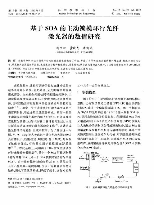


基于SOA的主动锁模环行光纤激光器的数值研究杨文艳;董晓龙;唐海燕【摘要】An actively mode-locked fiber ring laser with SOAs Is presented. The materal gain profile, spatial distribution of carriers and the broad-band spontaneous noise emission are considered in the model. The result of theoretical study and numerical simulations reveals that 7. 5 ps stable mode-locked pulse trains at repetition rate of 20 GHz can be obtained, and the pulse trains are constant over a 40 nm tuning range.%对基于SOA的主动锁模环行光纤激光器模型进行了研究,考虑了半导体光放大器的材料增益谱、载流子的空间分布、带宽放大自发辐射等因素,通过理论分析和数值模拟,得出结论:调节激光器的注入脉冲,可以输出重复频率为20 GHz,脉宽(FWHM)约为7.5ps的稳定锁模光脉冲序列,其波长可调谐范围超过40 nm.【期刊名称】《科学技术与工程》【年(卷),期】2012(012)019【总页数】4页(P4647-4650)【关键词】半导体光放大器;锁模脉冲序列;重复频率;交叉增益调制【作者】杨文艳;董晓龙;唐海燕【作者单位】重庆科技学院数理学院,重庆401331;重庆科技学院数理学院,重庆401331;重庆科技学院数理学院,重庆401331【正文语种】中文【中图分类】TN248.35高重复频率、波长可调谐的超短光脉冲源是高速率光纤通信系统、全光处理、全光网络中的重要组成部分。
锁模激光器的工作原理及其特性摘要: 本文主要介绍了锁模的基本原理和实现方法,并简单介绍了锁模激光器。
关键词:锁模,速率方程,工作原理一、引言如果在激光谐振腔内不加入任何选模装置,那么激光器的输出谱线是由许多分立的,由横纵模确定的频谱组成的。
锁模就是将多纵模激光器中各纵模的初相位关系固定,形成等时间间隔的光脉冲序列。
使各纵模在时间上同步,频率间隔也保持一定,则激光器将输出脉宽极窄、峰值功率很高的超短脉冲。
二、锁模的概念一般非均匀加宽激光器,如果不采取特殊选模措施,总是得到多纵模输出。
并且,由于空间烧孔效应,均匀加宽激光器的输出也往往具有多个纵模。
每个纵模输出的电场分量可用下式表示])-([),(q q z t i q q e E t z E ϕυω+= (2.1)式中,q E 、q ω、q ϕ为第q 个模式的振幅、角频率及初相位。
各个模式的初相位q ϕ无确定关系,各个模式互不相干,因而激光输出是它们的无规叠加的结果,输出强度随时间无规则起伏。
但如果使各振荡模式的频率间隔保持一定,并具有确定的相位关系,则激光器将输出一列时间间隔一定的超短脉冲。
这种激光器称为锁模激光器。
假设只有相邻两纵模振荡,它们的角频率差Ω='=L cq q πωω1-- (2.2)它们的初相位始终相等,并有01-==q q ϕϕ。
为分析简单起见,假设二模振幅相等,二模的行波光强I I I q q ==1-。
现在来讨论在激光束的某一位置(设为0=z )处激光场随时间的变化规律。
不难看出,在0=t 时,二纵模的电场均为最大值,合成行波光强是二模振幅和的平方。
由于二模初相位固定不变,所以每经过一定的时间0T 后,相邻模相位差便增加了π2,即πωω2-01-0=T T q q (2.3)因此当0mT t =时(m 为正整数),二模式电场又一次同时达到最大值,再一次发生二模间的干涉增强。
于是产生了具有一定时间间隔的一列脉冲,脉冲峰值光强为I 4,由式(2.3)可求出脉冲周期为cL T '=Ω=220π 如果二纵模初相位随机变化,则在0=z 处,合成行波光强在I 2附近无规涨落。
10 GHz pulses generated across a ~100 nm tuning range using a gain-shifted mode-lockedSOA ring laserW. W. Tang, M. P. Fok, and Chester ShuDepartment of Electronic Engineering and Center for Advanced Research in Photonics,The Chinese University of Hong Kong, Shatin, N.T., Hong Kong.ctshu@.hkAbstract: Widely-tunable picosecond pulses have been generated from aharmonically mode-locked semiconductor optical amplifier (SOA) ring laserwith a center wavelength spanning from 1491 to 1588 nm. An intra-cavitybirefringence loop mirror filter is used to define a 1.6 nm comb that governsthe wavelength spacing of the tunable output pulses. The filter also serves tocontrol the spectral gain profile of the laser cavity and thus extends thetuning range. By exploiting the spectral shift of the SOA gain with differentamount of optical feedback, the output can be obtained over a widewavelength range. Applying mode-locking together with the dispersiontuning approach, 10 GHz picosecond pulses have been successfullygenerated over a tuning range of 97 nm.©2006 Optical Society of AmericaOCIS code s: (140.4050) Mode-locked lasers; (140.3600) Lasers, tunableReferences and links1.M. Y. Jeon, H. K. Lee, K. H. Kim, E.H. Lee, S. H. Yun, B. Y. Kim and Y. W. Koh, “An electronicallywavelength-tunable mode-locked fiber laser using an all-fiber acoustooptic tunable filter,” IEEE Photon.Technol. Lett. 8, 1618-1620 (1996).2.J. M. Roth, T. G. Ulmer, N. W. Spellmeyer, S. Constantine and M. E. Grein, “Wavelength-tunable 40-GHzpicosecond harmonically mode-locked fiber laser source,” IEEE Photon. Technol. Lett. 16, 2009–2011 (2004).3. A. Bergonzo, E. Gohin, J. Landreau, O. Durand, R. Brenot, G. H. Duan and J. Jacquet, “Tuning range extensionby active mode-locking of external cavity laser including a linearly chirped fiber Bragg grating,” IEEE J. Sel.Top. Quantum Electron. 9, 1118–1123 (2003).4. D. N. Wang and X. H. Fang, “Generation of electrically wavelength-tunable optical short pulses using a Fabry-Perot laser diode in an external-injection seeding scheme with improved sidemode suppression ratio,” IEEE Photon. Technol. Lett. 15, 123-125 (2003).5.L. Schares, R. Paschotta, L. Occhi and G. Guekos, “40-GHz mode-locked fiber-ring laser using a Mach-Zehnder interferometer with integrated SOAs,” J. Lightwave Technol. 22, 859–873, (2004).6.X. Fang and R. O. Claus, “Polarization-independent all-fiber wavelength-division multiplexer based on aSagnac interferometer,” Opt. Lett. 20, 2146-2148 (1995).7.K. Tamura and M. Nakazawa, “Dispersion-tuned harmonically mode-locked erbium fiber ring laser for self-synchronization to an external clock,” Opt. Lett. 21, 1984-1986 (1996).8. D. Lingze, M. Dagenais and J. Goldhar, “Smoothly wavelength-tunable picosecond pulse generation using aharmonically mode-locked fiber ring laser,” J. Lightwave Technol. 21, 930–937 (2003).9.M. J. Connelly, “Wideband semiconductor optical amplifier steady-state numerical model,” IEEE J. QuantumElectron. 37, 439–447 (2001).10. F. W. Tong, W. Jin, D. N. Wang and P. K. A. Wai, “Multiwavelength fibre laser with wavelength selectablefrom 1590 to 1645 nm,” Electron. Lett. 40 , 594-595 (2004).11.K. L. Lee and C. Shu, “Alternate and simultaneous generation of 1-GHz dual-wavelength pulses from anelectrically tunable harmonically mode-locked fiber laser,” IEEE Photon. Technol. Lett. 12, 624–626 (2000). 12.K. Chan and C. Shu, “Compensated dispersion tuning in harmonically mode-locked fiber laser,” Appl. Phys.Lett. 75, 891-893 (1999).#9534 - $15.00 USD Received 15 November 2005; revised 16 January 2006; accepted 2 March 2006 (C) 2006 OSA20 March 2006 / Vol. 14, No. 6 / OPTICS EXPRESS 21581. IntroductionWavelength-tunable pulsed sources at high repetition rates are important for applications in optical communications and measurements. Among the different techniques to generate such pulsed source, active mode locking of a fiber ring laser provides a simple solution [1]. To define the output wavelength, the laser usually contains a wavelength selective element such as a fiber Fabry Perot (FP) filter [2], a fiber Bragg grating [3], or a FP laser diode [4]. In general, the wavelength selective elements will have a limited tuning range or gain bandwidth that restricts the tunability of the pulsed source. Hence, the bandwidth of the optical gain medium may not be fully utilized and most of the published works have tuning ranges of about 50 nm [5]. In this work, we demonstrate the generation of wavelength-tunable pulses with the dispersion tuning approach using a birefringence loop mirror filter (LMF) in a mode-locked semiconductor optical amplifier (SOA) ring laser. The LMF [6] is a passive, all-fiber, and polarization-independent device that serves as a comb filter in the laser. Thus, the output wavelengths can be tuned over a wide spectral range while maintaining a fixed grid spacing. In addition, with the controllable transmission ratio of the LMF, the SOA gain can be spectrally shifted to extend the wavelength tuning range of the laser. By applying the technique of dispersion tuning [7, 8], electrical tuning of 10 GHz mode-locked pulses has been achieved across a range of 97nm. 2. ExperimentThe experimental setup is shown in Fig. 1(a). A pigtailed SOA with a maximum small-signal gain of 25 dB is used to provide the cavity gain. The SOA is biased at 102.5 mA. The optical output is then connected to a birefringence LMF through a 90:10 coupler and an isolator. The LMF is constructed with a 5-m polarization-maintaining fiber (PMF) connected to the output ports of a 3 dB coupler. A polarization controller is placed in the loop filter and acts as a polarization state rotator for both the clockwise and the counter-clockwise propagating branches. The transmission characteristic of the LMF is shown in Fig. 1(b). An output comb with a spacing of ~1.6nm is obtained near 1550 nm. Another isolator is connected to the output port of the loop filter to block the amplified spontaneous emission (ASE) of the SOA from entering the loop in the opposite direction. The ring cavity is completed by connecting the isolator to the SOA through a dispersion compensating fiber (DCF), a polarization controller, and a LiNbO 3 Mach-Zehnder intensity modulator. The 25-m DCF provides a dispersion of -2 ps/nm at 1550 nm. The modulator is sinusoidally driven by a 27-dBm electrical signal at about 10 GHz. The modulator provides periodic loss modulation with a modulation depth of 94% to 96% throughout the tuning range. The fundamental frequency of the laser is 4.57 MHz and harmonic mode-locking is obtained near 10 GHz.Fig. 1. (a) Experimental setup of the wavelength tunable, harmonically mode-locked SOA ring laser that contains an intracavity birefringence loop mirror filter (LMF). DCF: dispersion compensating fiber; PC: polarization controller; PMF: polarization-maintaining fiber; SOA: semiconductor optical amplifier. (b) Measured transmission function of a 5-m LMF near 1550 nm.(a) (b) -90-80-70-60-50-40155015511552155315541555Wavelength (nm)I n t e n s i t yI n t e n s i t y (d B m ) #9534 - $15.00 USD Received 15 November 2005; revised 16 January 2006; accepted 2 March 2006(C) 2006 OSA 20 March 2006 / Vol. 14, No. 6 / OPTICS EXPRESS 21593. PrincipleThe key to achieve widely wavelength-tunable pulses using our dispersion tuning approach is the use of a LMF to shift the spectral gain of the SOA. The LMF defines a comb such that the output wavelength of the fiber laser can be tuned across a pre-determined wavelength grid. The working principle of the LMF is described as the following. The input light is split into two counter-propagating branches at the 3 dB coupler. After traveling through the fiber loop, the two branches will recombine again and interfere at the coupler. By controlling the polarization controller (PC) in the fiber loop, the counter-propagating branches are set to have a 90° polarization difference during their transit in the PMF. The light intensity that couples back to the cavity depends on the phase difference between the two interfering branches, and is related to the product of the modal birefringence and the length of the PMF. The transmission function is a wavelength dependent sinusoidal function given by()⎥⎦⎤⎢⎣⎡⎟⎠⎞⎜⎝⎛Δ−=λπλnL T 2cos 15.0 (1) The PMF defines the comb spacing (Δλ) given bynLλλΔ=Δ2(2) where Δn and L are the birefringence and the length of the PMF, respectively. In our work, a 5-m PMF with a birefringence of 3x10⁻⁴ is used, resulting in a wavelength spacing of 1.6nm at around 1550nm.The gain peak position of the SOA ring laser is dependent on the amount of the optical power in the cavity. A strong optical feedback tends to saturate the SOA, leading to gain compression and a shift of the gain peak towards a longer wavelength [9, 10]. The transmission ratio of the LMF is also tunable through adjustment of the PC. The function of adjusting the PC is to change the transmission ratio of the LMF and hence switch the gain band of the SOA between the short and the long wavelength region. The ring laser will oscillate in short wavelength band if the transmission ratio is low. Hence, the amount of cavity feedback power is controllable and the gain peak of the SOA can be tuned. Figure 2 shows the spectra of a continuous wave output that is generated by the SOA ring laser under different levels of the optical feedback. Figure 2(a) shows that the laser oscillates in the short wavelength region centered at 1513 nm when there is a large cavity loss. By adjusting the PC inside the LMF, a stronger feedback power can be obtained to support oscillation in the long wavelength region centered at 1582 nm, as shown in Fig. 2(b). The study shows that the output wave band can simply be tuned by adjusting the PC inside the LMF.Fig. 2. Output spectra of the SOA cw ring laser with (a) weak optical feedback, laser output centered at 1513 nm. (b) strong optical feedback, laser output centered at 1582 nm.(b)(a) R e l a t i v e I n t e n s i t y (5d B /d i v .)Wavelength (nm) 14801540 1600 R e l a t i v e I n t e n s i t y (5d B /d i v .)Wavelength (nm) 1480 15401600 #9534 - $15.00 USD Received 15 November 2005; revised 16 January 2006; accepted 2 March 2006(C) 2006 OSA 20 March 2006 / Vol. 14, No. 6 / OPTICS EXPRESS 2160Wavelength selection of the output pulses is performed by dispersion tuning [7]. The dispersion inside the cavity is provided by the 25-m DCF. As different wavelengths propagate at different group velocities in the DCF, adjustment of the modulation frequency will result in a corresponding tuning of the center mode-locked wavelength. Electrical tuning of the wavelength can be achieved by slightly varying the frequency applied to the modulator. The tuning relation can be expressed asDLF NF 2−≅δδλ (3)where D is the dispersion coefficient of the fiber, F is the mode-locking frequency, L is the length of propagation and N is the harmonic order. Since D is negative for a fiber providing a normal dispersion , a slight increase in the modulation frequency at a given harmonic will favor lasing at a longer wavelength. The pulsed output is coupled out of the cavity via a 90:10 coupler and is monitored using a 40GHz photo-detector and a 40GHz digital sampling oscilloscope. The spectral characteristic is measured with an optical spectrum analyzer with a 0.01 nm resolution. 4. Results and discussionWith the LMF, the output wavelength can be electrically tuned in steps of 1.6-nm. Figure 3(a) and (b) show some samples of the 10-GHz mode-locked pulses obtained at different center wavelengths within the 97-nm tuning range along with the corresponding optical spectrum. It is noted that the ground floor of the optical pulses is raised when the pulses are generated near the tuning edge at the short wavelength side. The observation is mainly caused by the incomplete suppression of the non-lasing modes.Fig. 3. Characteristics of the output at different wavelengths. (a) Pulse trains (Arrows indicatethe ground level). (b) Corresponding optical spectraIn Fig. 3(b), it is interesting to note the appearance of small peaks located at ~50 nm away from the output wavelength. The peaks are more pronounced when the output wavelength is near the edges of the tuning range. The observation is explained by simultaneous mode-Time (50ps/ div.)S i g n a lWavelength (nm)I n t e n s i t y (10 d B /d i v .)1490 1510 1530 1550 1570 1590(a) (b)#9534 - $15.00 USDReceived 15 November 2005; revised 16 January 2006; accepted 2 March 2006(C) 2006 OSA 20 March 2006 / Vol. 14, No. 6 / OPTICS EXPRESS 2161locking of two different center wavelengths in the ring laser [11]. The repetition rate of the output pulses is about 10 GHz, corresponding to a period of 100 ps. In principle, in order to obtain mode-locked output at only one center wavelength within the tuning range of 97nm, the amount of cavity dispersion should be less than 1.03ps/nm. However, the 25-m DCF provides a dispersion of ~2.0 ps/nm and thus dual-wavelength operation can be supported in our setup. Fortunately, by adjusting the LMF, the gain peak of the SOA can be arbitrarily shifted to the desired range to suppress one of the output wavelengths. Therefore, a single center mode-locked wavelength can be obtained throughout the whole tuning range.149015101530155015701590W avelength (nm)R e l a t i v e I n t e n s i t y (10d B /d i v .)Fig. 4. The superimposed optical spectra of the output pulses throughout the 97-nm tuning range.Figure 4 shows the superimposed optical spectra of the output pulses within the 97-nm tuning range from 1491.1 nm to 1587.7 nm. The wavelength spacing of neighboring outputs is 1.6 nm. The variations of the peak power and the pulse width at different output wavelengths are plotted in Fig. 5. The power varies between 0.4 and 2 mW, whereas the deconvolved pulse width spans the range of 18.6-26.4 ps. The time-bandwidth product of the output pulses varies between 0.53 and 1.00. The degradation of the output peak power near the edges of the tuning range is caused by the finite gain bandwidth of the SOA. The SOA in our setup has a gain peak at 1520 nm and a 3-dB bandwidth of ~45 nm. With the use of LMF to shift the gain peak of the SOA, the mode-locked laser can oscillate at 1587.7 nm that is about 68 nm away from the original gain peak. However, near the short wavelength region, the LMF will have no effect in extending the tuning range. In addition, since the intensity modulator cannot operate at the short wavelength side, the degradation of the peak power is more severe near the region.Figure 6(a) shows the variation of the signal-to-background suppression ratio across the tuning range. The highest value of 34.6 dB is obtained at 1533 nm. Degradation is more severe towards the edge of the tuning range in the short wavelength region, and is believed to be caused by the limited operating bandwidth of the modulator. During the 2-hour stability test, the SMSR varies less than 2.4 dB at both the short-wavelength and the long wavelength edges of the tuning curve. Moreover, less than 5% of pulse width variation is observed over the 1-hour measurement. Figure 6(b) shows the dependence of the output wavelength on the detuning of the modulating frequency. A linear plot with a slope of 10.56 nm/MHz is obtained from our experimental measurement. In our setup, the fundamental frequency is 4.57 MHz and the harmonic order is around the 2333rd. The measured slope of the tuning curve corresponds to a group velocity dispersion of 1.95ps/nm, in close agreement with the dispersion of ~2.0 ps/nm provided by the DCF. Although the frequency-varying tuning scheme has limitations in its application to communications, the source can be applied to highspeed testing of the spectral response of optical components. Alternatively, by including a#9534 - $15.00 USD Received 15 November 2005; revised 16 January 2006; accepted 2 March 2006(C) 2006 OSA 20 March 2006 / Vol. 14, No. 6 / OPTICS EXPRESS 2162variable air gap or by adoption of the compensated dispersion-tuning scheme [12], the modulation frequency can be kept unchanged during the tuning.Fig. 5. The variations of the peak power and the pulse width across the tuning range.Fig. 6(a) The signal-to-background suppression ratio of the output within the tuning range of1491.1 to 1587.7 nm. (b) The dependence of the output wavelength on the detuning of the modulating frequency.5. ConclusionWidely wavelength-tunable optical pulses have been generated in a harmonically mode-locked SOA fiber laser using the dispersion tuning approach. A birefringence loop mirror filter is used to define the grid spacing of the output wavelengths. By exploiting the controllable transmission ratio of the LMF and the spectral shift in the gain peak of the SOA, the tuning range of the output can be significantly enhanced. A tuning range of 97 nm has been successfully demonstrated. The 10 GHz optical pulses show an output signal-to-background suppression ratio as high as 34 dB. AcknowledgmentThe work described in this paper is supported by project grants from the Research Grants Council of Hong Kong (CUHK 4369/02E, CUHK 4196/03E)(a)(b)05101520253035401480150015201540156015801600Wavelength (nm)S u p p r e s s i o n r a t i o (10d B /d i v .)14801500152015401560158016000246810Frequency detuning (MHz)W a v e l e n g t h (n m )#9534 - $15.00 USD Received 15 November 2005; revised 16 January 2006; accepted 2 March 2006(C) 2006 OSA 20 March 2006 / Vol. 14, No. 6 / OPTICS EXPRESS 2163。