Probe Card Basics
- 格式:pdf
- 大小:205.88 KB
- 文档页数:10

P r o b e锁频测试步骤内部编号:(YUUT-TBBY-MMUT-URRUY-UOOY-DBUYI-0128)
P r o b e锁频和解锁步骤probe 以上版本自带功能,前期版本不是非常好,要点很多次,现在只需要点1-2次,显示success 就可以了,不现实成功success,power off之后再power on就可以了。
详细步骤!
1.打开软件,开启海思,将mifi连接到软件上,点击connect
2.点击工具栏上的Test→Forcing Fuction→LTE Forcing Feature,如下图所
示:
3.如果要求同时锁PCI和频点,在Function Select 中选择Lock EARFCN and
PCI,填入要锁定的PCI和频点后,单击Apply,如果只是锁定频点的话,在Function Select 中选择Lock EARFCN ,然后填入相应的频点就可以了,如下图所示:
4.右击海思,选择Command→Power Off,会弹出如下图所示的窗口,勾选UE#0,
然后再次右击海思,选择Command→Power On,在弹出的窗口中勾选UE#0。
5.上面1-4是锁频的步骤,锁频测试完成后,要求将mifi解锁,点击工具栏上的
Test→Forcing Fuction→LTE Forcing Feature,在弹出的窗口中选择Reset,如下图所示:
6. 右击海思,选择Command→Power Off,在弹出的窗口中勾选UE#0,然后再次
右击海思,选择Command→Power On,在弹出的窗口中勾选UE#0。

From Nuremberg BT-VS/MKP-XPT Product Management 20.04.2023Release LetterProduct: VIDEOJET decoder 7000 VJD-7513Version: Firmware 10.40.0055This letter contains latest information about the above-mentioned product.1. GeneralThis firmware release 10.40.0055 is a feature release based on FW 10.31.0005.Changes since last release FW 10.31.0005 are marked in blue.VIDEOJET decoder 7000 uses robust, fan-less technology designed for ambitious environmental conditions while providing maximum performance on minimum space in a nicely designed industrial housing.VIDEOJET decoder 7000 displays video from Standard Definition (SD), High Definition (HD), 4K Ultra High Definition (UHD), and Megapixel (MP) cameras and encoders using H.265, H.264 or MPEG-4 encoding at up to 60 frames per second over IP networks.VIDEOJET decoder 7000 is the successor of VIDEOJET decoder 8000 (VJD-8000, VJD-8000-N). It is using the same housing but comes with different video output interfaces and provides improved performance and functionality.Notes:•Firmware update may take several minutes due to a large cumulative Microsoft patch.•This firmware includes OpenSSL.From NurembergBT-VS/MKP-XPT Product Management 20.04.20232. Applicable products•VIDEOJET decoder 7000, VJD-75133. New Features•SRTP for encrypted multicast traffic is supported. This allows fully secured communication with and video streaming from CPP13 and CPP14 cameras in multicast environments.•SNMPv3 trap service has been added, including the support of SNMP-related RCP+ commands for configuration.• A JPEG snapshot is now possible from each of the displays, including JPEG quality settings parameter.•Display order can be re-arranged in case Windows display detection differs from mechanical order.•The default layout is depending on the display number to simplify the identification of display order. The number of video windows per display increases as square of the display number.•The web interface of the decoder has been updated to the latest style guide and re-structured to ease usage for installation, licensing, and integration purposes.o The new web pages provide links to documentation and include a live preview.o Maintenance log file creation and download is supported by a workflow mechanism.o A keyboard emulator supports initial setup for IP Matrix even without keyboard connected.From NurembergBT-VS/MKP-XPT Product Management 20.04.20234. Changes•The Video SDK as one of the core components for the decoder firmware has been updated to latest version 6.40, providing a great number of improvements and fixes, mainly aroundONVIF and RTSP support, increasing the overall robustness.•An issue is fixed for banner upload when banners are activated.•An issue is fixed for zooming out in client dewarping mode of panoramic camera streams.•An issue is fixed where client dewarping was not working on line 1 of a panoramic camera in onboard dewarping mode. Onboard dewarping is only available for lines 2 and higher, line 1 always provides the full warped image circle.•An issue with DNS server configuration is fixed.•An issue is fixed where CPP13 and CPP14 cameras were not correctly connected in camera sequences.•Maintenance log file download is improved, supported by the new web interface structure.•An issue is fixed where daylight saving time was incorrectly reflected in time zone offset calculation.5. System RequirementsFor configuration purposes:•Configuration Manager 7.61 or newerFor operation purposes:•Bosch Video Management System 12.0 or higherNote that not all features may be supported by BVMS yet.Please refer to BVMS release notes.From NurembergBT-VS/MKP-XPT Product Management 20.04.20236. Restrictions; Known Issues•Connecting encrypted streams without proper signalling may result in crashing the software decoder instance, resulting in black video displayed.•Alarms will not be signaled with a red border around the cameo if connection was established using CONNECT_PRIMITIVE.•Using CONNECT_PRIMITIVE via TCP is not possible.•CONNECT_PRIMITIVE does not support "first available" feature.•Audio may remain audible despite layout change to other than single view.•RCP+ command CONF_ALARM_CONNECT_TO_IP is not supported.•Alarm connection does not support audio, nor does it include metadata.•Maximum password length is 19 characters.•With “Reconnect last devices” active camera connections are stored and automatically reconnected after reboot. To avoid deadlock in case of an overload situation the automaticreconnect will be deactivated after the decoder was forced into reboot for ten times within 10 minutes.•Monitors may be swapped after update. Swap back is possible using Configuration Manager.•IP Matrix pre-requisites for multi-decoder clustering:o Fixed IP addresses must be assigned; DHCP configuration is not functional.o Passwords for service level must be same on all clustered decoders.o Passwords for user level must be same on all clustered decoders.•After removing a slave decoder from the IP Matrix master, both decoders must be restarted.•Camera sequences are paused when picture-in-picture mode is activated.•Time related settings may appear in Configuration Manager only with delay or after a reboot.•Monitors connected to the Display Port via USB-C may not always be detected during booting.In this case, unplug and reconnect the adapter or cable to the monitor. If only one monitor isused it is recommended to connect to the direct HDMI output.•Log file download stability may be affected by workload of decoder. As a workaround, the download may need to be repeated, or the workload of the decoder may need to be reduced (disconnect all camera streams).•Time zone configuration is only supported via TIME_ZONE_STRING.•The KBD-DIGITAL keyboard is locked automatically during start-up of the decoder, or with re-connect. It will be unlocked after entering the PIN but the lock screen will remain until the next action on the keyboard.•Certificates used with the decoder must not have any Windows policies defined.•DNS resolution is not implemented yet, thus time server entry only works with IP addresses.•Dewarping zoom does not work correctly for panoramic cameras in on-board dewarping mode for camera line 1.•Overload messages and traps may appear too sensitive in cases where display refresh rates are lower than video stream frame rates.From NurembergBT-VS/MKP-XPT Product Management 20.04.20237. Previous Revisions7.1. New Features with 10.31.0005•Support for HOST_NAME to get and set the device’s hostname; only supported in extended configuration mode.•Support for DNS_SERVER_IP_STRING to get and set primary and secondary DNS server IPv4 addresses.7.2. Changes with 10.31.0005•Optimized transparent data processing time to allow adequate transparent data pass-through for serial PTZ keyboard.•An issue is fixed to apply e-PTZ presets correctly in camera sequences.•Feature loss due to suppressing encrypted UDP multicast connections for Bosch IP cameras with firmware 8 and higher, and fall back to TCP, tunneled via HTTPS control connection.(This feature will be added again with FW 10.40.)From NurembergBT-VS/MKP-XPT Product Management 20.04.20237.3. New Features with 10.30.0005•The default setting for Automatic IPv4 address assignment is set to “DHCP plus Link-Local”.Though this might seem a small change, it may have an impact:The former default IP address 192.168.0.200 will virtually become obsolete.Instead, the camera will assign itself an auto-IP address out of the range 169.254.1.0 to169.254.254.255 as long as there is no other IP address assigned by a DHCP server.(https:///wiki/Link-local_address)The advantage is that there are no more duplicate IP addresses, which is consideredprohibited in a network.•Network authentication 802.1x with EAP/TLS has been added.Please note that the server certificate needs to get the usages ‘Trust’ and ‘EAP_TLS_Trusted’ assigned.The client certificate will get the necessary usages assigned automatically.•The possibility of large banner overlays has been introduced.o Banners can be uploaded as images that can be displayed over three areas: top, center and bottom. The images are scaled to fill the area and cropped wherenecessary.o Banners can be sequenced with a configurable dwell time.o Configuration Manager 7.60 is supporting this with upload and banner sequence configuration, including banner previews.•Set and recall prepositions for moving cameras (AUTODOME, MIC) as well as for ONVIF PTZ cameras via keyboard has been added to the IP Matrix functionality.•Images can be uploaded to the decoder for two purposes, using Configuration Manager. The images shall be in JPG format and must be named as follows:o‘monitor background’ image, shown as background of an empty video window: ‘Logo.jpg’o‘’no camera’ image, shown on connection failure: ‘NoCamLogo.jpg’7.4. Changes with 10.30.0005•An issue was fixed where uploading a new video loss image did not break the software seal.From NurembergBT-VS/MKP-XPT Product Management 20.04.20237.5. Changes with 10.23.0002• A security vulnerability has been fixed where a crafted configuration packet sent by an authenticated administrative user can be used to execute arbitrary commands in systemcontext (CVE-2021-23862).For more details refer to our Security Advisory BOSCH-SA-043434-BT, published at ourSecurity Advisory web pagehttps:///xc/en/support/product-security/security-advisories.htmlor visit our PSIRT website at https://.7.6. New Features with 10.22.0038•APIPA (link-local address, Auto-IP) is used instead of a default IP address when DHCP is on and no DHCP server responded.•Transparent data pass-through for serial PTZ keyboard (SERIAL_PORT_APP_VAL and TRANSFER_TRNSPARENT_DATA) has been added.•Support of RCP+ via CGI (including WRITE commands) has been added.•HTTP digest authentication is supported for RCP+ via CGI.•Display orientation can be changed per line via RCP+.•RCP+ WRITE command MONITOR_NAME now supported for custom monitor names.•Updated RCP+ documentation is now available via the VIDEOJET decoder webpage.•Download of screen and tile snapshots via snap.jpg is now supported (requires at least user privileges).•Firmware update on-screen countdown dialog now shows a heartbeat whenever a single update step takes longer.•Support of CONNECT_URL read queries to get current video connection details, including current digital and dewarping zoom settings, has been added.•Support of various digital and dewarping zoom persistence modes(DIGITAL_ZOOM_PERSISTENCE_MODE) has been added.•Support of SYSTEM_DATETIME_V2 to read/write UTC system time has been added.•Support for new Sentinel RMS licenses has been added. Legacy licenses can now also be based on new installation code (lock code from Sentinel RMS).From NurembergBT-VS/MKP-XPT Product Management 20.04.20237.7. Changes with 10.22.0038•IP Matrix initialization is now working also for camera lines larger than 1.•RCP+ response for query on connected cameras is now working correctly.•URL extension for camera configuration in IP Matrix is no longer truncated.•An issue with an unexpected application restart has been fixed.•The DECODER_GROUP command is no longer supported when decoder IP address is not static. This disables the whole IP matrix configuration pages in Configuration Manager until a static IP is configured in the decoder’s network settings.•Improvements were made for log export via webpage and via Configuration Manager.•KBD-DIGITAL keyboard PIN is now used immediately without application restart.•KBD-DIGITAL keyboard PIN is now required whenever keyboard is attached and at application start.•Display orientation is now working for further monitor types.•Support of further USB to serial COM port adapters for KBD-DIGITAL keyboard connectivity.o Current: Prolific PL2303 [hardware ID USB\VID_067B&PID_2303]o New: Prolific PL2303GT [hardware ID USB\VID_067B&PID_23C3]o New: ATEN UC232A [hardware ID USB\VID_0557&PID_2008]o New: Unitek Y-108 [hardware ID FTDIBUS\VID_0403+PID_6001]o CableCreation CD0489 (PL2303) [hardware ID USB\VID_067B&PID_2303] is compatible to the already supported Prolific PL2303 adapter.Please note that the KBD-DIGITAL keyboard connectivity requires continuous maintenance, since new or not listed USB-to-serial COM port adapters typically require the installation of a suitable driver on the VIDEOJET decoder and an adaption of the hardware ID filter in thekeyboard detection software module. Newer USB adapters may require a firmware update to become supported.From NurembergBT-VS/MKP-XPT Product Management 20.04.20237.8. New Features with 10.01.0036Security• A protected configuration mode has been implemented, allowing too enable SSD encryption (BitLocker) and too disable USB ports, e.g. for installation of the decoder in public areas.•The configuration of the decoder can be protected by Software Sealing, similar to IP cameras.•The latest Microsoft Windows security updates have been included.Miscellaneous• A dewarped cutout from panoramic cameras can be defined with PTZ coordinates.• A new way to control and integrate the decoder into a management system has been added by a JSON RPC API. This allows to send commands and retrieve status information via JSON remote procedure calls. The API documentation is added to the distribution package.• A video output capture service (VOCS) has been implemented which could be activated via a license, applicable per display output. This service captures the memory of the video outputand encodes it into a camera-like video stream, which can be recorded via Video StreamingGateway (VSG) onto iSCSI storage.• A time server can be added to synchronize the decoder.•Decoder log file can be downloaded via Configuration Manager. This is especially recommended when download of the log file is not working correctly via web browser.7.9. Changes with 10.01.0036•Upload of background image and connection loss image to the decoder and reverting them to default is now also possible with service password set. The former restriction is obsolete.•Various minor bug fixes.From NurembergBT-VS/MKP-XPT Product Management 20.04.20237.10. New Features with 9.60.0017IP Matrix enhancements•KBD-DIGITAL is supported in addition to KBD-UNIVERSAL XF.This keyboard requires a serial-to-USB adapter to connect to the decoder.Both keyboards can be mixed in a clustered multi-decoder IP Matrix, one keyboard perdecoder.•Playback from local recording is supported.Permission is configured via Configuration Manager for the whole IP Matrix, valid for all users.•Buttons for next and previous camera have been added to the KBD-UXF functions.•Audio can be switched on or off via keyboard.•Camera channels can be extended via license up to 64 cameras per decoder unit.Note:IP Matrix manual is now separated intoo One configuration manual for IP Matrixo One operation manual for IP Matrix using KBD-UXFo One operation manual for IP Matrix using KBD-DIGITALSecurity•The latest Microsoft Windows security updates have been included.Miscellaneous•Background image and connection loss image can be uploaded to the decoder, replacing the default images. Reverting them to default is done by uploading an empty image.Note: Upload is only possible in conjunction with an empty service password.7.11. Changes with 9.60.0017•Temperature control margin increased to improve maximum performance at the specified maximum temperature, covering component tolerances, and to ensure that all productsadhere fully to their specification.•Various minor bug fixes.Security SystemsFromNuremberg BT-VS/MKP-XPT Product Management 20.04.202311BOSCH and the symbol are registered trademarks of Robert Bosch GmbH, Germany 7.12. Features with initial release 9.51• VIDEOJET decoder 7000 displays video from Standard Definition (SD), High Definition (HD),4K Ultra High Definition (UHD), and Megapixel (MP) cameras and encoders using H.264 or MPEG -4 encoding at up to 60 frames per second over IP networks.• VIDEOJET decoder 7000 provides an HDMI and a DisplayPort (via USB-C connector) output, both capable of driving up to 4K UHD displays simultaneously.• Display settings are automatically discovered and set for optimal display performance. • Monitor layouts can be switched independently for each display.• Upright monitors (portrait mode) are supported.• Video window (cameo) aspect ratio can be set to 16:9, 9:16, 3:4, or 1:1.• Active camera connections and layout are stored and automatically reconnected after reboot if configured. To avoid deadlock in case of an overload situation the automatic reconnect will be deactivated after VIDEOJET decoder 7000 was forced into reboot for 3 times within 10 minutes.• Video smoothing can be configured.• RTSP connections are supported, enabling connectivity to 3rd party and ONVIF cameras. • Discovery port is configurable.• Cameo distance is configurable.• VIDEOJET decoder 7000 supports IP Matrix application as built-in feature.• VIDEOJET decoder 7000 is able to display VCA metadata.• VIDEOJET decoder 7000 provides bi-directional G.711 audio for the video stream shown in single view on the first monitor.• Configuration is done using the Configuration Manager.• The number of decoders presented in capabilities is configurable to regulate the consumption of VMS licenses. Default value is 30.• System access is password-protected with two levels.• The system firmware can be upgraded remotely.• System API is compatible to predecessor VIDEOJET decoder 8000 for easy plug-and-play integration.• Operating temperature iso 0 °C to +50 °C (+32 °F to +122 °F) ambient temperature, with airflow o 0 °C to +40 °C (+32 °F to +104 °F) ambient temperature, still airFor detailed functional description of inherited firmware features, please refer to the VIDEOJET decoder 8000 firmware 9.51 release notes.For detailed technical specification, please refer to the datasheet.。
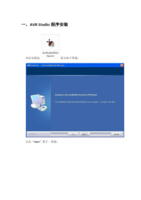
一、AVR Studio程序安装双击安装包显示如下界面:点击“Next”到下一界面:选择“I accept…”点击“Next”到下一界面:选择你需要安装的位置。
点击“Next”到下一界面:将勾号点上,点击“Next”到下一界面:点击“Install”,进入下一界面:软件安装中,请耐心等待几分钟。
此过程中不要任何操作,等待此命令串口结束后,软件安装完成。
二、仿真器驱动安装将仿真器的usb线插入电脑上,提示下面安装要求:选择自动安装软件,点击下一步后电脑会自动安装仿真器驱动程序。
打开设备管理器查看驱动是安装正确:三、运行AVR Studio软件第一次运行AVR Studio软件,需要进行一些设置,并且要将仿真器连接上电脑。
在开始菜单中“程序—AVR Tools—AVR Studio 4”打开AVR Studio软件:打开软件界面后:直接点击“Cancel”,进入下一界面:点击第二排工具栏中的AVR或Con图标,如上图所示,进入下一界面:选择“JTAGICE mkll”和“AUTO”,点击“Connect”,若出现下面提示界面,即软件和仿真器连通。
此时仿真器若未连接主板或DHS板将无法进行任何操作,直接关闭即可。
四、主板程序烧写主板程序烧写准备工作:1、连接好仿真器与电脑,仿真器与主板(接口在主芯片边十芯牛耳插座);2、打开主板供电;3、按照第三章节打开AVR Studio软件;在小窗口中,选择第一个“Main”菜单项,如下图:本菜单项中,必须按照上图所示进行设置:1、第一个方框中必须选择“ATmega1280”;2、第三个方框中必须选择“JTAG mode”;上面设置完成后,点击第二个方框后面的“Read Signature”,就会显示如上图所示的第二方框中熔丝位信息,同时小窗口最下面提示栏中会提示各种信息OK,主板连接成功。
在小窗口中选择第三个菜单“Fuses”,检查“Mina”菜单中第二个方框中熔丝位信息是否正确(“Read Signature”读取的信息都是正确的,这里提供手动检查,防止程序烧写后无法正常运行),如下图所示“Fuses”菜单项。

LCD 驱动与控制电路BL55022BL55022是一款通用型TN/STN 液晶控制和驱动芯片,具有256位显示单元的输出能力,适用于字符/图形/点阵式液晶屏幕。
BL55022具有较宽的工作电压范围和环境条件,同时还有适合各类微机系统的3或4线通讯接口。
特点特点● 工作电压2.4~ 5.2V ● 内嵌256KHz RC 振荡器 ● 1/4偏压,1/8占空比 ● 片内时基频率源● 节电命令可用于减少功耗● 内嵌时基发生器和看门狗定时器WDT ● 时基或看门狗定时器溢出输出 ● 一个32 x 8 的LCD 驱动器● 一个内嵌的32 x 8 位显示RAM 内存 ● 3/4线串行接口 ● 片内LCD 驱动频率源 ● 软件配置● 数据模式和命令模式指令● 提供VLCD 管脚用于调整LCD 操作电压产品列表产品列表管脚说明管脚说明BL550XX BL550XXBL55021BL55021BL55022BL55022BL55066BL55066BL55076BL55076COM COM 4 8 4 4 SEG SEG3232 3232 2424 4040管脚号管脚号管脚名称管脚名称 功 能能 1 CS 使能控制 3 READ 测试时使用 4 CPW 数据写入控制 5 DI 数据输入 6 Vss 电源负端 7 CPI 系统控制时钟 8 Vdd 电源正端 9 Vlcd LCD 工作电源 10 TIS 测试时使用,响应信号 11、13 TB1、TB2 测试时使用,频率信号17,18,20~25Row1~Row8 背板输出 26~32, 36~48,53~64Dot0~Dot31点位输出 2,12,14,15,16,19,33,34,35,49,50,51,52NC未使用结构框图结构框图管脚排列管脚排列极限参数极限参数参参 数数 符符 号 参数范围参数范围参数范围 单单 位位 电源电压 V DD -0.3~5.5V 输入电压 V IL Vss-0.3~ V DD +0.3 V工作温度 Topr -40~ +85 oC贮存温度Tstg-50~ +125oC直流电参数直流电参数 (除非特别指明, Ta=25oC)测试条件测试条件测试条件 符号符号 参参 数V DD 条条 件 最 小 值 典型典型 值 最大最大 值 单位单位Vdd 工作电压---- ---- 2.7 ---- 5.2 V 3V ---- 80 210 I DD1 5V空载/LCD显示用芯片上RC谐振器 ---- 135 415 uA 3V ---- 8 30 I DD2 工作电流5V空载/LCD不显示用芯片上RC谐振器 20 55 uA 3V ---- 1 8 I STB 待机电流 5V空载待机模式 ---- 2 16 uA Vil 输入低电压 5V C、DI、CPW 0 1.0 V Vih 输入高电压 5V C、DI、CPW 4.0 5 V Rph上拉电阻5V DI 50 100 150 kΩ交流电参数交流电参数 (除非特别指明, Ta=25oC)测试条件测试条件测试条件 符 号 参参 数 V DD 条条 件 最小最小 值 典型典型 值 最大最大 值 单位单位 3V 22 32 40Fsys1系统时钟 5V片上RC谐振器 24 32 40 kHz 3V ---- 32 ----Fsys2系统时钟 5V外部时钟源 ---- 32 ---- kHz 3V 44 64 80Flcd1LCD扫描时钟 5V片上RC谐振器 44 64 80 Hz 3V ---- 64 ----Flcd2LCD扫描时钟 5V片上RC谐振器 ---- 64 ---- Hz 3V ---- ---- 150 Fclk 通信时钟 5V 占空比50% ---- ---- 300 kHz Tc 复位脉冲宽度 C ---- 250 ---- ns 3V 3.34 ---- ---- Tclk 控制脉冲宽度 5V 1.67 ---- ---- us Tr,Tf 升降沿宽度---- 120 ---- ns Tsu 对DI数据准备 ---- 120 ---- ns Th 对DI数据保持 ---- 120 ---- ns Tsu1 对C时钟准备 ---- 100 ---- ns Th1对C时钟保持---- 100 ----ns系统说明系统说明显示内存显示内存RAM RAM RAM静态显示内存RAM 以64 x 4位的格式储存所显示的数据RAM的数据直接映象到LCD 驱动器。

Si53108-EVB Si53108 E VALUATION B OARD U SER’S G UIDEDescriptionThe Si53108-EVB can be used to evaluate the Si53108-A01AGM, an 8-output PCIe Gen1/2/3 buffer that can operate in either fanout or zero delay mode.Features⏹ 10-inch traces to evaluate signal integrity⏹ The signal traces of the input and outputs have asingle-ended impedance of 50 ohms, anddifferential impedance of 100 ohms.⏹ The series resistance on the outputs are set tomatch to this impedance design.⏹ DC pin controls per data sheet specification.⏹ Ability to measure input to output propagationdelay.⏹ Ability to measure PCIe clock jitter.⏹ Ability to program features of Si53108-A01AGMvia I2C interface.Si53108-EVB2SkyworksSolutions,Inc.•Phone[781]376-3000•Fax[781]376-3100•*********************•1. SchematicsFigure 1.Schematic 1Si53108-EVBSkyworksSolutions,Inc.•Phone[781]376-3000•Fax[781]376-3100•*********************• 3Figure 2.Schematic 2Si53108-EVB4SkyworksSolutions,Inc.•Phone[781]376-3000•Fax[781]376-3100•*********************•Figure 3.Schematic 3Si53108-EVBSkyworksSolutions,Inc.•Phone[781]376-3000•Fax[781]376-3100•*********************• 52. Input and Power Supply SequencingThe Si53108-A01AGM should be powered up with supply at both the VDD and VDD_IO nodes (at the jumpers available on the EVB). A 100MHz or 133MHz HCSL input clock should be applied to pins 8 and 9. There is no internal or on-board resistive termination, therefore HCSL termination needs to be provided at the input if needed by the driver. The input clock should be applied only after the supplies are stable.3. Quick Start Guide:1. Enable supply on the VDD pin.2. Enable supply on the VDDIO pin.3. Apply input clock on the SMA connectors CLK_IN/CLK_IN# and measure the return path clock on CLK_IN_RET, CLK_IN#_RET.Figure 4.Clock Return Patha. The input clock measured at J32, J33 needs a 50-ohm termination on the scope.b. The attenuation will be 1:10 after the above termination. Appropriate scaling (10x) needs to be set at the scope to adjust for the scaling.4. The output clocks are now set up and can be measured on an oscilloscope or frequency domain measurement instrument.4. Usage of the EVB1. Once the EVB has been set up, the following can be evaluated:2. Signal integrity of the device when driving 10-inch, 100-ohm differential traces.3. Effect of capacitance load on output signal integrity.4. Output-to-output skew over 10-inch traces.5. Input-to-output prorogation delay in BYPASS, HBW, and LBW modes using the input clock return path.6. Measuring the power consumption of the device.7. Modification of the device settings via the I 2C interface.Copyright © 2021 Skyworks Solutions, Inc. All Rights Reserved.Information in this document is provided in connection with Skyworks Solutions, Inc. (“Skyworks”) products or services. These materials, including the information contained herein, are provided by Skyworks as a service to its customers and may be used for informational purposes only by the customer. Skyworks assumes no responsibility for errors or omissions in these materials or the information contained herein. Skyworks may change its documentation, products, services, specifications or product descriptions at any time, without notice. Skyworks makes no commitment to update the materials or information and shall have no responsibility whatsoever for conflicts, incompatibilities, or other difficulties arising from any future changes.No license, whether express, implied, by estoppel or otherwise, is granted to any intellectual property rights by this document. Skyworks assumes no liability for any materials, products or information provided hereunder, including the sale, distribution, reproduction or use of Skyworks products, information or materials, except as may be provided in Skyworks’ Terms and Conditions of Sale.THE MATERIALS, PRODUCTS AND INFORMATION ARE PROVIDED “AS IS” WITHOUT WARRANTY OF ANY KIND, WHETHER EXPRESS, IMPLIED, STATUTORY, OR OTHERWISE, INCLUDING FITNESS FOR A PARTICULAR PURPOSE OR USE, MERCHANTABILITY, PERFORMANCE, QUALITY OR NON-INFRINGEMENT OF ANY INTELLECTUAL PROPERTY RIGHT; ALL SUCH WARRANTIES ARE HEREBY EXPRESSLY DISCLAIMED. SKYWORKS DOES NOT WARRANT THE ACCURACY OR COMPLETENESS OF THE INFORMATION, TEXT, GRAPHICS OR OTHER ITEMS CONTAINED WITHIN THESE MATERIALS. SKYWORKS SHALL NOT BE LIABLE FOR ANY DAMAGES, INCLUDING BUT NOT LIMITED TO ANY SPECIAL, INDIRECT, INCIDENTAL, STATUTORY, OR CONSEQUENTIAL DAMAGES, INCLUDING WITHOUT LIMITATION, LOST REVENUES OR LOST PROFITS THAT MAY RESULT FROM THE USE OF THE MATERIALS OR INFORMATION, WHETHER OR NOT THE RECIPIENT OF MATERIALS HAS BEEN ADVISED OF THE POSSIBILITY OF SUCH DAMAGE.Skyworks products are not intended for use in medical, lifesaving or life-sustaining applications, or other equipment in which the failure of the Skyworks products could lead to personal injury, death, physical or environmental damage. Skyworks customers using or selling Skyworks products for use in such applications do so at their own risk and agree to fully indemnify Skyworks for any damages resulting from such improper use or sale.Customers are responsible for their products and applications using Skyworks products, which may deviate from published specifications as a result of design defects, errors, or operation of products outside of published parameters or design specifications. Customers should include design and operating safeguards to minimize these and other risks. Skyworks assumes no liability for applications assistance, customer product design, or damage to any equipment resulting from the use of Skyworks products outside of Skyworks’ published specifications or parameters.Skyworks, the Skyworks symbol, Sky5®, SkyOne ®, SkyBlue™, Skyworks Green™, Clockbuilder ®, DSPLL ®, ISOmodem ®, ProSLIC ®, and SiPHY ® are trademarks or registered trademarks of Skyworks Solutions, Inc. or its subsidiaries in the United States and other countries. Third-party brands and names are for identification purposes only and are the property of their respective owners. Additional information, including relevant terms and conditions, posted at , are incorporated by reference.Portfolio/ia/timingSW/HW/CBProQuality/qualitySupport & Resources/supportSkyworksSolutions,Inc.|Nasdaq:SWKS|*********************| USA: 781-376-3000 | Asia: 886-2-2735 0399 | Europe: 33 (0)1 43548540 |。

FSB-200(A) and FSB-200S(A)Single-Ended, Reflector-TypeAddressable Beam Smoke DetectorDN-6985:C • H-212GENERALThe Notifier FSB-200 and FSB-200S are intelligent,addressable reflected beam smoke detectors for protectingopen areas with high and sloping ceilings, and wide-openareas, where spot-type smoke detectors are difficult to installand maintain. Ideal applications are atriums, cathedralceilings, aircraft hangars, warehouses, sporting arenas,concert halls, and enclosed parking facilities. They arecompatible with the NFS-3030, NFS2-3030, NFS-640, NFS2-640, and NFS-320 in FlashScan® or CLIP mode, as well aslegacy addressable panels. Installation of the single-endedreflective design is much quicker than a dual-ended projectedbeam detector. Alignment is easily accomplished with anoptical sight and a two-digit signal strength meter incorporatedinto the beam detector. Listed for operation from –22°F to131°F, the FSB-200 and FSB-200S are usable in open areaapplications where temperature extremes exceed the designlimits of other types of smoke detection.The FSB-200 and FSB-200S are a transmitter/receiver unitand a reflector. When smoke enters the area between the unitand the reflector it causes a reduction in the signal strength.When the smoke level (signal strength) reaches thepredetermined threshold, an alarm is activated. The detectorshave four standard sensitivity selections as well as twoAcclimate® settings. When either Acclimate® setting is selected, the detector’s advanced software algorithms automatically adjust to the optimum sensitivity for the specific environment.The FSB-200S has an integral sensitivity test feature of a filter attached to a servomotor inside the detector optics. Activation of the RTS151 or RTS151KEY remote test stations moves the filter into the pathway of the light beam, testing the detector’s sensitivity. This sensitivity test feature allows the user to quickly and easily meet the annual maintenance and test requirements of NFP A 72, without physical access to the detector. The servomotor must be powered by +24 VDC, not SLC power.FEATURES•Listed to UL 268, ULC CAN/ULC S529.•T ransmitter/receiver built into same unit.•Six user-selectable sensitivity levels.•16' to 328' (use BEAMLRK beyond 230') protection range.•Removable plug-in terminal blocks.•Digital display — no special tools required.•Built-in automatic gain control compensates for signal dete-rioration from dust buildup.•Optional remote test station.•Optional long-range kit (BEAMLRK) for applications in excess of 230' (70 m).•Optional multi-mount kit (BEAMMMK) providing ceiling or wall mount capability with increased angular adjustment.•Optional heater kits (BEAMHK and BEAMHKR) for prevention of condensation (not intended to increase orreduce the specified operating temperature).•Paintable cover.SPECIFICATIONSOPERATIONAL SPECIFICATIONSProtection Range: 16 to 230 feet (5 to 70 m), 230 to 328 feet (70 to 100 m) using optional BEAMLRK kit.Adjustment Angle: ±10° horizontal and vertical. Note that the optics move independently of the unit.Sensitivity (6 levels):NOTE: Sensitivity settings are a feature of specific control panels.•Level 1 — 25%.•Level 2 — 30%.•Level 3 — 40%.•Level 4 — 50%.•Acclimate® Level 5 — 30% to 50%.•Acclimate® Level 6 — 40% to 50%.Fault Condition (trouble):•96% or more obscuration blockage.•In alignment mode.•Improper initial alignment.•Self-compensation limit reached.Alignment Aid:•Optical gunsight.•Integral signal strength indication.•Two-digit display.Indicators:•Alarm — local red LED and remote alarm.•Trouble — local yellow LED and remote trouble.•Normal — local flashing green LED.FSB-200 withReflective PlateFSB-200 withBEAMMMK6975reflect.jpg6975beammk.jpgTest/reset features:•Integral sensitivity test filter (FSB-200S only, requires external power supply).•Sensitivity filter (incremental scale on reflector).•Local alarm test switch.•Local alarm reset switch.•Remote test and reset switch (compatible with RTS151 and RTS151KEY test stations).Smoke Detector Spacing: On smooth ceilings, 30 – 60 feet (9.1 to 18.3 m) between projected beams and not more than one-half that spacing between a projected beam and a sidewall. Other spacing may be used depending on ceiling height, airflow characteristics, and response requirements. See NFPA 72.ENVIRONMENTAL SPECIFICATIONS Temperature: –22°F to 131°F (–30°C to 55°C).Humidity: 10 – 93% RH noncondensing.ELECTRICAL SPECIFICATIONS •Voltage: 15 to 32 VDC.•Average Standby Current (24 VDC): 2 mA maximum (LED flashing, SLC @ 24 V).•Alarm Current (LED on): 8.5 mA maximum.•Trouble Current (LED on): 4.5 mA maximum.•Alignment Current: 20 mA maximum.•External Supply (FSB-200S only):Voltage — 15 to 32 VDCCurrent — 0.5 A maximum.•Remote Output (Alarm):Voltage - 15 to 32 VDC (Output voltage same as deviceinput voltage)Current - 15 mA maximum, 6 mA minimum (Output current is limited by 2.2K ohm resistor)•Heater Kit BEAMHK:Voltage - 15 to 32 V; Current - 92 mA maximum @ 32 V (heater only); Power Consumption -nominal 1.6 W @ 24 V, maximum 3.0 W @ 32 V.•Reflector Heater Kit BEAMHKR:Voltage - 15 to 32 V;Current - 450 mA maximum @ 32 V (per reflector); Power Consumption (per reflector) - nominal 7.7 W @ 24 V,maximum 15.0 W @ 32 V.MECHANICAL SPECIFICATIONSShipping Weight: 3.7 lbs (1.68 kg)Detector Dimensions: 10.0" H x 7.5" W x 3.3" D (254 mm H x 191 mm W x 84 mm D).Reflector Dimensions for 16' to 230' (5 to 70m) Applications: 7.9" x 9.1" (200 x 230 mm).Reflector Dimensions for Applications Beyond 230'/70m: 15.7" x 18.1" (400 x 460 mm).SENSITIVITY SELECTIONThe detector has six sensitivity selections (sensitivity settings are a feature of specific control panels). Each of these selections is only acceptable over a specific distance separation between the detector and the reflector per UL 268. The chart below determines which selections are acceptable for your installed distance. The sensitivity of the detector can be set only when the housing is removed and the detector is not in the fine adjustment step of the alignment mode, indicated by the illumination of the dual digital display. T o set the sensitivity, depress the sensitivity button one time. See Switch Locations diagram. Once the switch is pressed, the digital display will illuminate and read the current sensitivity setting in percent obscuration. To change the sensitivity, continue to depress the sensitivity switch until the desired setting is achieved. The digital display will turn off automatically if no further switch presses occur.In addition to the four standard sensitivity selections, the detector has two Acclimate® settings. When either Acclimate®setting is chosen the detector will automatically adjust its sensitivity using advanced software algorithms to select the optimum sensitivity for the environment. The sensitivity will be continuously adjusted within the ranges specified in the chart above.Total obscuration can be converted to percent per foot, assuming uniform smoke density for the entire length of the beam. The chart below converts total obscuration percent per foot for all acceptable sensitivity settings.SensitivitySettingPercentObscurationDisplayReadingAcceptableDISTANCEbetweenDetectorandReflector(ft)AcceptableDISTANCEbetweenDetectorandReflector(m) Level 125%2516.4 to 120 5.0 to 36.6 Level 230%3025 to 1507.6 to 45.7 Level 340%4060 to 22018.3 to 67 Level 450%5080 to 32824.4 to 100 Acclimate ®Level 130% to 50%A180 to 15024.4 to 45.7 Acclimate ®Level 240% to 50%A280 to 20024.4 to 67Table 1: Total ObscurationWiring Diagram with RTS151/KEYWiring Diagram6985graph.tif6985wirerts151.tif Alignment and Adjustment Locations6985adjloc.tif Housing Screw Locations6985screwlocs.tifPARTS LISTItem QuantityT ransmitter/Receiver Unit 1Paintable Trim Ring 1Reflector 1Plug-In Terminal Blocks 3Isolator Shunts 2Instruction Manual 1Orange Sticky Paper 1FSB-200/FSB-200SSee RTS151/KEY Installation Instructionsfor electrical ratings of the RTS151/KEYRTS151/KEYPin 1Pin 2Pin 4Pin 3Pin 5Remote Alarm OutAUX (-)Reset InputTest InputSee electricalratings.or Previousdevice.32 VDC MaximumTwisted pair isrecommendedDeviceAcclimate® Plus™ is a trademark of Honeywell International Inc.©2009 by Honeywell International Inc. All rights reserved. Unauthorized use of this document is strictly prohibited.This document is not intended to be used for installation purposes. We try to keep our product information up-to-date and accurate. We cannot cover all specific applications or anticipate all requirements.All specifications are subject to change without notice.For more information, contact Notifier. Phone: (203) 484-7161, FAX: (203) 484-7118.AGENCY LISTINGS AND APPROVALSThese listings and approvals apply to the devices specified in this document. In some cases, certain modules or applications may not be listed by certain approval agencies, or listing may be in process. Consult factory for latest listing status.•UL Listed: S2522 (FSB-200, FSB-200S)•ULC Listed: S2522 (FSB-200A, FSB-200SA)•CSFM: 7260-0028:228•MEA: 95-04-E•Maryland State Fire Marshal: Permit # 2167•FM ApprovedPRODUCT LINE INFORMATIONFSB-200: Intelligent beam smoke detector FSB-200A:Same as FSB-200 with ULC Listing.FSB-200S:Intelligent beam smoke detector with integral sen-sitivity test.FSB-200SA: Same as FSB-200S with ULC Listing.BEAMLRK: Long range accessory kit (required for applica-tions in excess of 230 ft/70 m).BEAMMMK:Multi-mount kit (provides ceiling or wall mount capability with increased angular adjustment).BEAMSMK: Surface-mount kit.RTS151: Remote test station.RTS151A: Same RTS151 with ULC listing.RTS151KEY: Remote test station with key lock.RTS151KEYA: Same as the RTS151KEY with ULC listing.BEAMHK: Heating kit for use with the transmitter/receiver unit of FSB-200S. For prevention of condensation.BEAMHKR: H eating kit for use with the reflector on FSB-200S. For prevention of condensation6500-MMK: Heavy-duty multi-mount kit for installations prone to vibration or where there is difficulty mounting the set angle.When installed with the transmitter/receiver unit, the 6500-SMK must be used as well.6500-SMK: Surface-mount kit (required when using 6500-MMK to mount transmitter/receiver).BEAMMMK(ceiling or wall mount kit sold sepa-rately)RTS151RTS151KEYBEAMHK6975b e a m m k .j p gr t s 151.w m frts151key.wmf6985hk.tif。
博科存储网络运维指导手册V ERSION 1.02016年7月文档修订记录文档编号:标题博科存储网络运维指导手册摘要本文档是为博科存储网络定制的运维指导手册当前版本V1.0创建日期2016-7文档作者舒磊文件名称博科存储网络维指导手册.doc修改记录日期修改人编写者摘要目录文档修订记录.................................................................................................................................... I I 目录.................................................................................................................................................. I II 前言 (1)文档目的 (1)编写环境 (1)适用人员 (1)内容范围 (1)一、网络架构描述 (2)二、主要运维场景 (4)1.端口故障 (4)具体现象 (4)故障信息确认 (4)故障处理 (7)影响范围 (14)预计处理时间 (14)验证方案 (14)2.磁盘访问故障 (15)具体现象 (15)故障信息确认 (15)故障处理 (15)影响范围 (17)预计处理时间 (17)验证方案 (17)3.端口板故障 (18)具体现象 (18)故障信息确认 (18)故障处理 (19)影响范围 (20)预计处理时间 (20)验证方案 (21)4.引擎故障 (21)具体现象 (21)故障信息确认 (21)故障处理 (22)影响范围 (24)预计处理时间 (24)验证方案 (24)5.风扇故障 (24)故障信息确认 (24)故障处理 (26)影响范围 (26)预计处理时间 (27)验证方案 (27)6.电源故障 (27)具体现象 (27)故障信息确认 (27)故障处理 (28)影响范围 (29)预计处理时间 (29)验证方案 (29)7.CR故障处理过程及方法 (29)具体现象 (29)故障信息确认 (29)故障处理 (30)影响范围 (32)预计处理时间 (33)验证方案 (33)8.边缘交换机整机故障 (33)具体现象 (33)故障信息确认 (33)故障处理 (34)影响范围 (34)预计处理时间 (34)验证方案 (34)9.核心光纤交换机整机故障 (35)具体现象 (35)故障信息确认 (35)故障处理 (35)影响范围 (36)预计处理时间 (36)验证方案 (36)三、主要变更场景 (37)1.微码升级 (37)配置备份 (38)微码升级 (38)校验微码升级 (40)微码升级常见问题 (40)2.新设备上线 (43)3.新增ZONE配置 (62)4.修改CFG、ZONE、A LIAS的名字 (64)5.删除ZONE或Z ONE的成员 (65)7.交换机扩容 (69)补充命令介绍 (71)F RAMELOG --SHOW 指令: (71)F ABRICLOG --SHOW 指令: (72)前言文档目的此文档主要用于工行博科存储网络的日常变更操作、故障处理以及存储网络的规模扩展,帮助行内博科SAN岗维护人员快速定位修复故障、熟悉日常变更操作流程,以及提高博科SAN日常运维效率。
R F I D设备选型方案一、概述市场上RFID的种类繁多,广泛应用于物流、制造业、医疗卫生、安全防伪等各个领域。
RFID分为读写设备、电子标签以及业务应用展示等几部分。
对于RFID在无线电台站管理中的应用,主要包括RFID标签选择、读写设备选择、以及RFID在台站系统的具体业务应用等几部分。
本项目旨在解决服装管理、资产管理等系统在使用RFID过程中的硬件设备选型,以及给子系统提供的对硬件的读、写及数据传输接口,不需要知道实际业务应用。
二、RFID标签选型方案尽管识别技术有多种选择,但是兼顾成本及技术成熟度以及服装、仓储和自身设备的实际特点,以二维条码和无线射频识别(RFID)为首选。
二维条码虽然具有信息容量大、成本低,易制作、可用多种阅读设备阅读等特点,但RFID技术具有条形码所不具备的防水、防磁、耐高温、使用寿命长、存储数据容量更大、存储信息更改自如等优点,在物品管理中更具有优势。
RFID具有足够的信息存储能力,能够将相关信息存储到芯片中,便于现场快速识别比对。
安全性和防伪性高,RFID承载的是电子式信息,其数据内容可经由加密算法保护,使其内容不易被伪造及变造。
可重复使用,RFID标签则可以重复地新增、修改、删除RFID卷标内储存的数据,方便信息的更新。
可承载相关信息的动态。
抗污染能力和耐久性好,抗干扰能力强。
对物品进行管理时,环境比较复杂,有的在机房内部、有的设备可能在室外,RFID标签防水、防磁、耐高温,可以在低劣的作业环境下工作,使用寿命较长。
目前RFID使用的频率跨越低频(LF)、高频(HF)、超高频(UHF)、微波等多个频段。
RFID频率的选择影响信号传输的距离、速度等,同时还受到各国法律法规限制。
针对不同类型项目中的应用,我们主要选择超高频(UHF)射频标签。
超高频标签优点:读写距离较远,可以发射至1-5米(与标签的天线有关,纽扣式的标签,发射距离不超过0.5米)。
缺点:对环境及其他硬性条件有要求(金属、水类对标签距离有影响)。
Probe Card BasicsThis section is intended to provide general information about the function of a probe card, as well as an introduction to its primary components. This is not to provide any specific manufacturing instructions, but simply to help answer the question, “What is a probe card?”The type of probe card introduced here is generally known as an epoxy-type probe card. The technology is relatively simple and in contrast to the rapid advances being made in IC device technology each year, the epoxy-type probe card has remained relatively unchanged. With smaller device sizes and increasingly tight requirements, however, industry is beginning to demand an advance in probe card technology as well. New materials and manufacturing methods are slowly being introduced. In spite of these changes, the epoxy-type probe card has remained an integral part of the IC testing process.General Function1.1 The Integrated CircuitSemiconductor Integrated Circuits (ICs) are essential in today’s high-tech society. They can be found at the heart of a variety of products, from the simplest calculators to the fastest computers. As a result, the production of ICs has become a billion dollar industry, involving some of the world’s most advanced technology. Probe cards are important in the final phase of this production process, playing a vital role in the testing and measuring of integrated circuits.Integrated circuits are built from round, thin sheets of semiconducting material. Standard sheets, or wafers, are commonly made of silicon. These wafers can range from 5 cm (~2 in) to 20 cm (~8 in) in diameter and are roughly 0.10 cm (~0.04 inch) thick. On a single wafer, anywhere from 50 to 200 identical integrated circuits, or die, can be made. The process of taking a simple silicon wafer and creating from it circuitry which can use and store electricity is a complex process. In a sense, the circuitry is “embedded” in the silicon, just below its surface. Within this microscopic maze of circuitry, electrical signals flow from one point to the next, much in the same way that water flows in a riverbed. To interact with the world outside of the IC, these signals are passed back and forth through small metal pads attached to the wafer’s surface (see Figure 1-1). The ability to make electrical contact with these metal pads is critical. Without some method of making this contact, the integrated circuit can not be used.Figure 1-1: Integrated Circuit Wafer1.2 Testing the ICIn the testing of integrated circuits, probe cards play this vital role of contacting the metal pads on awafer’s surface. ICs are tested by large machines, called testers, which send a series of electrical signalsto each IC. During testing, the probe card and IC are held in place by another machine, called a prober.The prober might be described as the "arm" of a tester, doing the mechanical work of moving andaligning the probe card and IC. The probe card then functions primarily as the "hand" of a tester, allowingit to "touch" the metal pads on a wafer’s surface (see Figure 1-2). This establishes an electricalconnection between tester and IC, allowing signals to flow freely between them. An ICs response tothese test signals then indicates whether it has been made correctly. Good ICs can then be separatedfrom bad ones. Probe cards are at the center of this testing process.Figure 1-2: IC Tester and Prober (with probe card and wafer)With the help of the prober, the probe card is lowered onto the IC wafer until the probe tips come into contact with the wafer’s metal pads. Test signals can then be passed between tester and IC.Figure 1-3: Probe Card and WaferThe movement of the probes as they touch the surface of the metal pads is also important. Generally, the surface of each metal pad is covered by a very thin layer of glass-like material, called an oxide. In order to make contact with the metal underneath, the probe tips must break through this thin oxide.Because the probes are very thin, roughly 0.250 mm (~0.010 in) in diameter, they flex when touching the wafer. As they flex, the probe tips slide, or scrub, across the surface of the pads (See Figure 1-4). This scrubbing action causes the probe tips to break through the surface oxide, helping make good electrical contact with the metal underneath.Figure 1-4: Probe Scrub ActionAlthough its basic function is relatively simple, building a probe card requires precise and careful work. Probe cards are an assembly of a variety of parts, some fragile and some sturdy. In the following chapters, you will be introduced to the primary components which make up a standard probe card. Because no two probe cards are exactly the same, each component is described in its most common form.Probe2.1 FunctionEarlier in section 1.0, a probe card was described as the “hand” of the tester. If we think of a probe card in this way, the probes then function as its "fingers." As was shown in Figure 1-4, the probe is the part of a probe card that actually makes contact with the integrated circuit.2.2 Straight ProbesFigure 2-1: Straight Probe (not to scale)Generally, if probes are purchased from a vendor, they arrive just as shown above in Figure 2-1. They are straight, thin, needle-like pieces of metal, with one end that tapers down into a sharp point. Probes are most commonly made of Tungsten (W), although materials such as Beryllium Copper (BeCu), Palladium (Pd), Rhenium Tungsten (ReW) are also used. J-Probe is a new probe material developed by JEM America. [See J-ProbeTM System for details onJ-Probe.] A straight probe is defined by four basic parameters: material, probe length (L), probe diameter (D), and taper length (T). Common material and dimensions are listed below in Table 2-1.Table 2-1: Straight Probe parameters2.3 Bent ProbesFigure 2-2: Bent ProbeBefore a probe card is assembled, the tapered end, or tip, of these straight probes must be bent. Again, depending on a customer’s specifications, these tips can be bent at a variety of angles, although 103 degrees is standard. Throughout the assembly process, the shape of a probe remains just as it has been bent, with a sharp, pointed tip. After a probe card has been fully assembled, however, these probe tips are sanded down to create a desired tip diameter (d) and tip length (l). Including the parameters from Table 3-1, a bent probe is defined by seven parameters, which are listed below in Table 2-2.Table 2-2: Bent Probe parametersRing3.1 FunctionA probe card ring’s basic function is straight forward. It is simply a sturdy piece of material to which the probes are attached. Once the probes are attached to the ring, they can conveniently be handled and operated as a single unit.3.2 MaterialAlthough a ring’s basic function is purely mechanical, the type of material it is made from is very important. A ring must be•sturdy, to give the probes a firm foundation,•electrically non-conductive, to protect the test signals being passed through each probe,•able to withstand high temperatures, sometimes as high as 200 deg C (~392 deg F).To meet all of these requirements, ceramic is often used.3.3 ShapeThe size and shape of a ring depends on the IC device which will eventually be tested. It is most common for the pads to be arranged along the outer edge of an IC device. When probing a single die, this results in a ring that is most often square or rectangular, as shown in Figure 3-2.Figure 3-2: Standard Rectangular RingRings, too, come in all shapes and sizes. A few examples are shown below in Figure 3-3.3.4 EpoxyIn order to attach the probes to the ring, a special glue, or epoxy, is used (see Figure 3-1). Although the ring provides support for the probes, it is the epoxy which actually holds the probes in place. After curing, an epoxy generally has properties similar to those of the ring. It must be very sturdy, electrically non-conductive, and be able to withstand high temperatures. In addition, an epoxy must adhere itself well to both the ring and the probes, in order to hold the probes in position.A variety of epoxies are used in the probe card industry. Some are designed for high temperature applications, while others are designed for low leakage applications. The epoxy which is used for any individual probe card depends primarily on the customer’s requirements.Printed Circuit Board4.1 FunctionThe largest of the components which make up a probe card is the board. It functions both as a support for the assembled ring, as well as the point where test signals are passed from the probes to the prober. Because the test signals pass through the board, it is also a convenient place to mount components, such as capacitors, resistors, and relays. These components can then help in manipulating and controlling the test signals as they are passed back and forth between tester and IC.4.2 Material and ShapeA few different materials are used in making a board, the choice of which depends on a customer’s testing temperature and leakage requirements. As was true of both the ring and epoxy, the main board material must also be electrically non-conductive. A type of fiberglass, FR-4, is commonly used, as well as polyimide. To carry the test signals, thin strips of metal run along the top and bottom of the board.Unlike the ring and probes, which are designed entirely to match the IC, the board is designed to match the prober. For this reason, boards come in many sizes. Although there are many sizes, they come in two basic shapes: round and rectangular. Round boards commonly range in diameter from 5.7 cm (~2.25 in) to 34 cm (~13.5 in), while rectangular boards are roughly 11.5 cm (~4.5 in) X 21.5 cm (~8.5 in).Figure 4-1: Common Boards (bottom side view)Figure 4-2: Round Board, Trace and T-Pin Location4.3 TracesThe thin strips of metal located on the bottom-side (or ring-side) of a board are called traces (see Figure 4-1). It is here that the probes are soldered to the board (see Figure 4-2). These traces are very much the same on most boards, regardless of size or shape.4.4 T-pin, Pogo Pad, and Edge ConnectorAs was mentioned in section 4-1, the board must also connect to the prober. While the probes are generally soldered to the traces near a board’s center, the prober connection is usually made near a board’s outer edge. The way this connection is made depends on the type of prober, but there are generally three methods which are used. They are as follows:Table 4-1: The Board/Prober ConnectionKey ParametersHere is a general diagram of a completed probe card, labeled with a few of the more important parameters. See the following table for additional explanation.Figure 5-1: Probe Card and WaferTable 5-1: Key Parameters。