发电机安装使用维护说明书 英文
- 格式:doc
- 大小:76.50 KB
- 文档页数:6

FDSL系列小型风力发电机用户安装使用手册FDSL series small wind generators User installationmanual2致用户首先我们感谢您购买、使用我公司生产的小型风力发电机,并为能向您提供产品和服务而感到自豪。
我们建议您在安装、使用FDSL系列小型风力发电机前,详细阅读本《用户安装使用手册》,以保证您更加熟悉产品、并进行正确地安装、连接及使用。
请妥善保管本《用户安装使用手册》以备将来查阅。
本《用户安装使用手册》的编制依据GB/T19068.1-2003《离网型风力发电机组第1部分:技术条件》、GB9969.1-1998《工业产品使用说明书总则》和JB/T5995-1992《工业产品使用说明书机电产品使用说明书编写规定》的有关要求。
3To consumerFirstly, we are thankful for your purchasing, using our products -the small wind generators, and we are proud of being able to provide you with the products and servicesRead this "user installation and use handbook.” carefully before you install or use the product.Please keep this "user installation using manual” properly for future reference.This handbook is based on GB/T19068.1-2003”from the nets type WTG part 1: technical conditions”, GB9969.1-1998 "industrial product manuals general "and T5995-1992 "JB/industrial product manuals electromechanical products instructions written provisions of relevant requirements.4目录致用户 (3)1 产品组成、特点和用途 (7)2产品规格 (7)3产品的使用环境 (7)4 工作原理 (9)5装箱清单 (10)6安装步骤 (11)7 接线流程 (13)8使用注意事项 (14)9特别提示 (15)10常见故障排除指南 (16)11 定期检查 (17)12特别声明 (18)13风力等级表 (19)5ContentsTo consumer (3)1 the product composition, characteristics and uses (7)2 product specification (7)3 Product use environment (7)4 Working principle (9)5 Packing list (10)6 Installation steps (11)7 Wiring process (13)8 using cautions (14)9 Special hints (15)10 Common trouble shooting guides (16)11 Regular inspection (17)12 Especially declare (18)13 Wind rating table (19)6SLM型水平轴小型风力发电机用户安装使用手册1产品组成、特点和用途FDSL系列小型风力发电机是一种水平轴风力发电机,主要由风叶、永磁式发电机、集流转向装置、尾翼连杆和尾翼、整流桥、控制器、逆变器等部分组成,适合在风力资源较好、市电保证不便的地区或场合使用,如海岛、边防哨所、牧场、农场、通讯基站、风光互补、野外作业等,根据风力资源的情况可以部分或完全取代市电,满足在其额定输出功率范围内各种用电器的用电要求,具有工作噪声低、使用免维护、可靠性高、安装架设方便、工作寿命长等特点。
INSTALLATION MANUAL FOR 600MW/660MW/680MWTURBINE GENERATOR600MW/660MW/680MW汽轮发电机安装说明书Document No.(文件号) : AQ-9Document Code:文件编码AQ-9Rev. CDongfang Electric Machinery Co., Ltd. 东方电气集团东方电机有限公司2012-09-24REV. CINSTALLATION MANUAL FOR 600MW /660MW/680MW TURBINE GENERATOR AQ-9DONGFANG ELECTRIC MACHINERY CO., LTD. 第 1页Contents 目录CHAPTER 1: GENERAL第一篇:总论1. Site Check, Acceptance and Storage for Equipment ………………………… 设备的清点验收及现场保管2. Preparation and Requirement for Installation ……………………………………安装前的准备工作及施工要求3. Weight List for Major Parts (estimated)………………………………………… 主要起吊零部件重量(粗略值)4. Installation Flow Chart …………………………………………………………… 安装流程图CHAPTER 2: PROCEDURE FOR INSTALLATION第二篇:分部安装说明 1. Making of Flowable Grout Pads & Installation of Foundation Plate …………… 浮动水泥墩的灌浆制作及基础板的安装2. Assembly of Stator …………………………………………………………………定子装配3. Inspection of Hydrogen Cooler ……………………………………………………氢气冷却器的安装4. Stator Teminal Assembly ……………………………………………………………定子出线装配5. Preliminary Centering of Stator ……………………………………………………定子初找中心6. Insertion of Rotor ……………………………………………………………………穿转子7. Installation of Bearing ………………………………………………………………发电机轴承安装8. Measurement of Air-gap between Stator and Rotor ………………………… 定、转子空气隙的测量9. Installation of Fan ……………………………………………………………………风扇装配10. Installation of Upper End Bracket and Centering of Generator ………………发电机的封盖、找正及定位11. Installation of Oil Gland Seal and Deflector ……………………………………油密封及挡油盖装配12. Generator Air Leakage Test ………………………………………………… 发电机整体试验13. Final installation of Bearing …………………………………………………………轴承总装配2 3 4 1012 14 31 33 37 39 46 49 50 52 58 6975INSTALLATION MANUAL FOR 480MW GAS TURBINE GENERATOR AQ-9DONGFANG ELECTRIC MACHINERY CO., LTD.第 2页14. Installation of Brush Holder & Steady Bearing …………………………………碳刷架及稳定轴承安装15. Inspection and Test Before Starting ……………………………………………启动前的检查与试验Fig.1-6 Figures for Inserting Rotor ………………………………………………… 图1-6穿转子示意图CHAPTER 3: QUALITY CONTROL RECORD OF GENERATOR 第三篇:发电机质量控制记录QCR1001~5003………………………………………………………………………76 81 8698-134INSTALLATION MANUAL FOR 600MW/660MW/680MWTURBINE GENERATOR600MW/660MW/680MW 汽轮发电机安装说明书CHAPTER 1: GENERAL第一篇:总论This installation manual is applicable to “600MW/660MW/680MW” turbinegenerator supplied by DFEM. Three types of stator are distinguished as follows according to their structure and mode of transportation.本安装说明书用于东方型600MW/660MW/680MW 汽轮发电机,按照定子结构形式和运输方式可分为如下3种类型: ¾ Single-stator整体定子结构Description: For this type of stator, the stator should be transported as a single one.描述:对于此种结构的定子,定子作为一个整体进行运输。

REV 1.0/0607ENGGAThree-phase Synchronous Generators 三相同步发电机Operation & Maintenance Manual安装和维护手册安全指南EG发电机采用最新的发电机设计、生产工艺、质量控制理念,拥有出众性能、可靠质量、优质发电机。
敬请各位用户在使用前务必仔细阅读和理解本手册中有关发电机安装、使用和维护的内容。
安装、调试、检修必须由具备相关工作资格的专业人员进行,操作人员应能掌握正确的使用方法、安全操作,否则有可能引起严重的人员伤亡或设备损坏事故。
①警示标识本手册中使用和随发电机提供的警示和警告标识的含义如下,发电机组配套商应确保警示标签位置放置正确并清晰,标签含义如下:A.普通警告标识,可能会导致人员伤亡、设备损坏的危险B.电气危险标识,可能电气原因会导致人员伤亡的直接危险C.通用危险标识,可能会导致人员伤亡的直接危险② 发电机警告标签的位置目录1 概述1.1 标准1.2 发电机型号代表意义1.3 铭牌1.4 接收检查及储存2 发电机的使用环境2.1 使用环境2.2 发电机的容量修正3 发电机结构3.1 发电机的工作原理3.2 定子3.3 转子3.4 励磁系统4 安装4.1 安装环境4.2 安装4.3 转向4.4 接线4.5 接地、保护5 运行5.1 运行前的检查5.2 运行前的试验调整5.3 开机与停机5.4 并联运行6 维护和检修6.1 一般维护6.2 检修项目6.3 发电机的拆装6.4故障现象及排除6.5 A VR故障检修7 结构图结构图零件表本安装使用维护手册阐述了英格EG系列交流发电机的结构特点、性能原理、安装使用和维护检修。
1 概述1.1 标准发电机符合下列国际和相关国家标准:I.E.C 60034-1 国际电工委员会标准BC5000 英国标准NEMA MG21 美国标准C.S.A C22-2 加拿大标准VDE 0530 德国标准GB755 中国标准1.2 发电机型号意义:EG发电机的型号按照以下方式命名例如:EG280S—120NEG---表示EG系列发电机280---表示发电机的机座号(160、225、280、315、355、400、500)S---表示机座的长短(M、L)120---表示发电机的容量带,KWN---表示发电机的改进、用途,N---新改进的NEW系列;H---船用系列;B---变形产品1.3 铭牌发电机铭牌位于驱动端右侧机体上。
MOTOYAMA Titanium Series Professional Power GeneratorOWNER’S OPERATING MANUAL TM1800/TM1800ETM2800/TM2800ETM3800/TM3800ETM4800/TM4800ETM5800/TM5800ETM6800/TM6800EPREFACEThank you for purchasing MOTOYAMA Titanium Series gasoline generatorWe want to help you get the best results from your new generator and to operate it safely. This manual contains the information on how to do that, please read it carefully. This owner’s manual describes the operation and maintenance of the MOTOYAMA Generator. All the information in this publication is based on the latest product information available at the time of printing. MOTOYAMA reserves the right to make changes at any time without notice and without incurring any obligation. No part of this publication may be reproduced without written permission. This manual should be considered a permanent parts of the generator and should remain with it if it is unsold.IMPORTANT NOTICESPlease pay special attention to statements by the following words:△WARNINGA warning is used to alert the user to fact that hazardous operating and maintenance procedures may result in injury to or death of personnet if not strictly observed.CAUTIONA caution is used to alert the user to fact that hazardous operating and maintenance procedures may result in damage to or destruction of equipment if not strictly observed.NOTEA note is used to give helpful information.This manual should be considered as a permanent part of the unit and should remain with the unit when resold.Contents1 Generator Safety (4)2 Introduction to Parts and Components (6)3 Pre-Operating Inspection (7)4 Starting the Engine (11)5 Service (13)6 Stopping the Engine (18)7 Maintenance (19)8 St orage (23)9 Troubleshooting (25)10 Assembly of parts (27)11 Specifications (29)12 Wiring D iagram (30)App endix Warranty Evidence (34)1 GENERATOR SAFETY1.1 Never operate it in an enclosed room(Fig.1) . 1.3 Never connect it to home circuit(Fig.3).1.2 Do not operate it under wet circumstances1.4 Place inflammables away from the unit (Fig.2).at least one meter(Fig.4).1.5 No smoking when filling fuel(Fig.5).1.6 Do not spill out when filling fuel(Fig.6)1.7 Always fill fuel after stopping it(Fig.7)2 INTRODUCTION TO PARTS AND COMPONENTSMain components of the unit are located as follows :Fig. 71. Fuel sensor 9. Starting handle2. Fuel filler cap 10.Fuel cock3. AC plug socket 11.Air cleaner4. AC breaker 12.Chock lever5. Voltmeter 13. Ground terminal6. Dipstick 14.Muffler7. Ignition switch 15.Spark plug8. Drain plug3 PRE-OPERATING INSPECTION3.1 ENGINE OIL LEVELNOTE: Always check the generator in the case of stopping the generator on a level ground.3.1.1 Turn out the oil 3.1.3 In the case thatfiller cap and clean the the oil level is belowdipstick with a clear the lower level markcloth(Fig.9) of the dipstick, fill oilto the upper level markof the dipstick(Fig.11)3.1.2 Insert the dip-stick back into the oilfiller hole withoutturn ing it in(Fig.10) 3.1.4 Reinstall the oilfiller cap well(Fig.12)3.2 FUEL LEVEL3.2.1 Open the fuel filler cap (Fig.13)3.2.3 Fill fuel to the shoulder of the fuel (Fig.15)3.2.2 Check the fuel level, and fill fuel if necessary(Fig.14) 3.2.4 Reinstall the fuel filler cap well(Fig.16)3.3 AIR CLEANER3.3.1 Remove the air cleanerhousing (Fig.17) 3.3.4 Put the filter element intothe original position, install the 3.3.2 Check and makecover and secure it well(Fig.19)sure the air cleaner coreis intact and clean.If itis broke,replace it with anew one.3.3.3 If the core is filthy,Clean it in the followingSequence(Fig.18)a) Clean the core in thecleaning solvent.b) Dry it upc) Dip a few drops of en-gine oil into it.d)Squeeze excess oil.5GF-4) 3.4 BATTERY(only for 4GF-4&Check and make sure that theelectrolyte level of each battery cell is between is upper and lower levelmarks(Fig.20).1.upper level mark2.lower level mark4 STARTING THE GENERATOR4.1 Remove all loads from AC socket. 4.4 Set the choke lever to OFF position (Fig.23)4.2 Switch off the AC breaker(Fig.21)Don’t close the choke when starting th e engine in hot condition.4.3 Turn on the fuel cock(Fig.22)4.5 Turn on the ignition switch(Fig.24) 4.7 Once the engine is warmed up, set the choke lever to ON position (Fig.26)4.6 Pull the start handle gentling until feeling an anti-action,and then pull it up strongly(Fig.25). △WARNINGAfter starting up, release the starting lever slightly so avoid injuring personnel or damaging equipment due to its bouncing back.5 SERVICEAlways do as the following as to keep the generator in a sound condition. △WARNING5.1 Always connect the generator to the earth to preventmisusing(Fig.27)5.2 The following table gives reference information for connecting electric appliances to the generator.5.3 If the generator is to supply two or above loads with power supply, be sure to connect them one by one with higher start current first(Fig.28).5.4 Connencting methods are illustrated as follows(Fig.29).a)Correctc)Correctb)Fobidden△WARNINGWhen connect the generator to home power supply,be sure that a skilled electrician does this job.Improper connecting between the generator and loads may cause damage to the generator,even a fire.5.5 USE INSTRUCTION WHEN PROVIDING ALTERATIVE CURRENT SUPPLY5.5.1Start the generator (Fig.30). 5.5.3 The unit is able to supply 110/220V.Setthe voltage selector to position suitabletoequipment(Fig.32).5.5.2 Connect devices(Fig.31). 5.5.4 Swith on the AC breaker(Fig.33).6 STOPING THE ENGINE6.1 Switch off the ACbreaker(Fig.34) 6.3 Set the fuel cock to OFF(Fig.36)6.2 Turn the ignition switch to OFF (Fig.35).To stop the generator in an emergency,Turn the ignition switch to OFF.MAINTENANCEUser should service the unit according to the maintenance schedule as follows:7.1REPLACEMENT OF ENGINE OIL7.1.1 Turn and then take out the dipstick(Fig.37).7.1.2 Unscrew the drain plug, and empty the engine oil from the crankcase.7.1.3 Screw on the drain plug(Fig.38).7.1.4 Fill engine oil to the upper level mark of the dipstick.Engine oil recommended:4-stroke gasoline oil-engine oil class SE,SF from API Srviceclassification or SEA 10W-30 engine oil equivalent to Class SG.7.1.5 Fit the dipstick to the original position.7.2 SPARK PLUG7.2.1 Withdraw the 7.2.2 Dismantle the spark 7.2.4 Check the spark plug capSpark plug cap front the plug by means of a special and adjust if necessary.The cap Spark plug(Fig.39). tool(Fig.40). should be 0.7-0.8mm(Fig.42).7.2.3 Clear away carbon fouling around the spark7.2.5 Reinstall the spark plug and plug(Fig.41).cap well(Fig.43).Spark plug recommended:F6RTC7.3 MAINTENANCE OF FUEL FILTER CUP7.3.1 Set the fuel cock to OFF,and disdmantle7.3.3 Fit the fuel filter cup and gauze to the the fuel filter cup and gauze(Fig.44).original position(Fig.45). 7.3.2 Fit the fuel filter cup and gauze to theoriginal position.8 STORAGEDuring long-term storage of the unit which are not kept in use. Carry out procedures as follows:8.1 Empty the fuel from the fuel tank(Fig.46)8.2 Having wash the fuel cup and gauze,Install them to the original position.8.4 Turn off the oil filler cap and oil drainplug ,and the empty the engine oil from thecrankcase(Fig.48).8.3 Discharge the fuel from the carburetor(Fig.47).8.5 Reinstall the oil drain plug,fill engine oil to 8.6 Pull up the starting handle gently The upper level mark of the dipstick,followed until an anti-action(Fig.50).by fitting the oil filler cap to the original pod-sition(Fig.49).8.7 Place the generator set in the cleanarea(Fig.51).9 TROUBLESHOOTING9.1 TROUBLE: the generator fails to 9.1.3 Check the fuel inside tank(Fig.55). Start(Fig.52).9.1.4 Remove the spark plug, and check 9.1.1 Check to see if the ignition switch it for proper sparks(Fig.56).is at ON(Fig.53).9.1.5 If the generator set is still out of work, see your dealer for help(Fig.57).9.1.2 Check engine oil level(Fig.54)9.2 TROUBLE: the unit fails to generate electricity.9.2.1Check the light bulb(Fig.58).9.2.2 Check to see if the AC breaker is at ON(Fig.59).9.2.3 If such check is still unsatisfactory, see your dealer for help(Fig.60).10 ASSEMBLY OF PARTSAssemble the wheels, to this end:10.1.1 Fit the wheel onto the axle,thensecure them with washer and split pin.10.1.2 Mount the assembled axle on the Feame with bolt and nut.Fig.611.Inner side2.Shorter side3.Longer side4. Latch5.Stopping disc6.Engine location7.Retainer 8.Split pin9.Wheel 10.Right axle(close to engine) 11.Left axle(close to generator)12.Nut 13.Bolt10.2 BATTERY(Fig.62)To install the battery,procced as follows: Array 10.2.1 Assemble the battery with nuts,bolts and washers.10.2.2 Connect the starting cable to the starting motor terminal alone the bottom of the fuel tank.10.2.3 Connect the earth line with the rear end of the generator.10.2.4 Connect the starting cable to the positive lead of the battery first,and then to the negative one.Disconnect in the reverse order.Fig.621. Starting motor2. Starting cable3. Protective frame4. Battery bracket5. Battery guard6. retaining frame7. Battery (with a rating of 12V-35Ah)8. Negative wireAPPENDIXINSTRUCTIONS FOR THE WARRANTY CERTIFICATE1. Keep the certificate well.2. Be familiar with the warranty details IMPORTANT NOTEin the certificate. The evidence will be kept as one of the owner’s in-3. When you draw the certificate, pay portent documents,so,be sure to give the evidence to theattention to item in the certificated filled by seller.your seller. TO OWNERS:When purchasing a new product in a seller,be sure to COMMODITIES PURCHASING EVIDENCE read carefully the following in the table and be sure tomake a mark O beside the description which youunderatand,at last,sign your name.Agree with all the details contained in the warrantycertificate and accept them。
电机安装与维护英语作文Electric Motor Installation and Maintenance。
Electric motors are widely used in various industries and play an important role in the production process. However, improper installation and maintenance can lead to motor failure and even accidents. Therefore, it is necessary to understand the correct installation and maintenance methods of electric motors.Installation。
Before installing the electric motor, it is necessary to check whether the motor model, voltage, power, and rotation direction meet the requirements of the equipment. In addition, the installation location should be dry, ventilated, and free of dust, and the ambient temperature should not exceed the rated value of the motor.The installation process should be carried out inaccordance with the instructions provided by the manufacturer. The motor should be placed on a flat surface and fixed with bolts. The alignment of the motor shaft and the equipment shaft should be checked to ensure that they are parallel and concentric.After the motor is installed, it is necessary to check the insulation resistance of the motor winding with a megohmmeter. The insulation resistance value should be greater than the specified value, and the motor should be grounded reliably.Maintenance。
QF系列18~22MW汽轮发电机安装使用维护说明书MANUAL FOR18~22MW TURBO-GENERATOROF QF SERIES0JS・461・402 编制 TRANSLATOR: 刘红蕾 校核 CORRECTOR: 薛守栋 李 霖批准 APPROVER:时间D A T E: 2004.6山东济南发电设备厂SHANDONG JINAN POWER EQUIPMENT FACTORY THE PEOPLE’S REPUBLIC OF CHINA目录Content1.概述第 2 页General2.安装地点及使用条件第2 页Installation site and working conditions3.结构说明第 4 页Structure introduction4.安装说明第 12 页Installation5.使用说明第 18 页Operation6.维护检修说明第 26 页Maintenance7.无刷励磁机使用维护说明 第33 页Brushless Exciter type Operation and Maintenance Instruction 8.保证期第 40 页Guarantee period1. 概述本系列汽轮发电机为QF系列18~22MW空冷三相两极交流同步发电机,额定转速为3000r/min,频率为50Hz。
发电机设计为封闭循环通风系统,径向双流式通风系统。
发电机型号:如QF(NW)-18-2型,QF代表空冷汽轮发电机,18代表容量18兆瓦,2-代表2极,N 代表双支点,W代表无刷励磁方式。
本系列发电机有无刷励磁和静止励磁两种励磁方式供选择。
此系列汽轮发电机的旋转方向,从汽轮机端看为顺时针方向。
GeneralAll this series of Air-Cooled turbo-generators are three-phase, two-pole, synchronous generators whose powers range from 18 MW to 22 MW. Their rated speed and frequency are 3000r/min, 50Hz. The design of generators is closed and circular aeration system and radial double-flow aeration system. Generators model: For example QF(NW)-18-2, QF means Air-Cooled turbo-generators, 18 means Power is 18MW, 2 means 2 poles, N means two supports, W means Brushless Exciter type. This series of generators have two Exciter types, brushless exciter and static exciter. All this series of generators clockwise rotate when looking from driving-end.2. 安装地点及使用条件Installation site and working conditions:2.1 安装地点海拔不超过1000米。
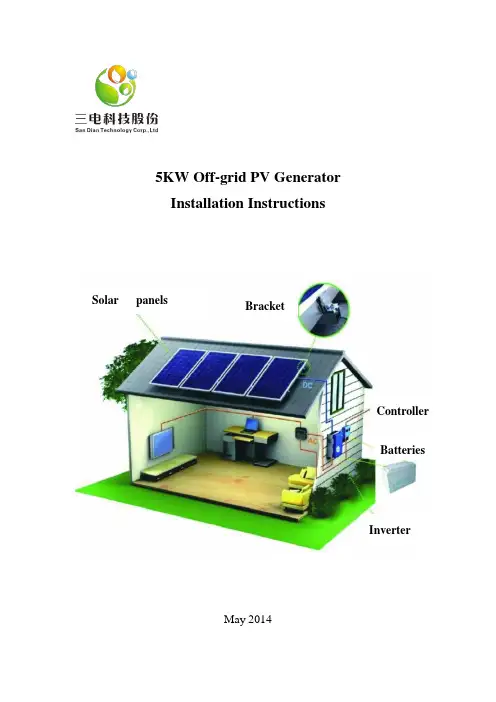
5KW Off-grid PV GeneratorInstallation InstructionsMay 2014Solar panels BracketControllerBatteriesInverterFirst, the purpose of this manualThis manual provides PV module (hereinafter referred to as "components") the installation and use of information.Before installation, the installer must read and understand this manual, if you have any questions, please contact the company for further explanation. Meanwhile, when install the components , please observe all of this manual safety precautions and local laws and regulations.Before installing solar power systems, installers should be familiar with the mechanical and electrical requirements of this system, please keep this manual for future reference when maintenance or component need to sell or need to be addressed.Second, the GeneralInstallation of solar photovoltaic systems requires specialized skills and knowledge, it must be made by qualified engineers . Each component comes with a permanently attached junction box. For easy installation, the company provides customer demand prefabricated cables. Installers should know in advance the risk of injury (including electric shock and other injuries.) that may occur during the installation, Individual components in direct sunlight can produce more than 30V DC voltage, and the contact voltage above 30V is dangerous.twoDo not disconnect the cable under load conditions.Component can convert light energy into DC energy, component applied to the ground, roofs, vehicle or vessel, and other outdoor environments. Rational design and use of the support structure is a system designer or installer's responsibility.Do not disassemble the assembly, movement or adhere to any part of any nameplate on the assembly.Do not paint or other adhesive on the surface of the component (glass surface).threeDo not use mirrors or lenses to focus sunlight onto the component. When the component installation, shall comply with all local regions and countries relevant laws and regulations , the relevant permit is needed when it necessaryThird, the security processing①Properly package the components before installation .②Hold the junction box can not be directly handling components.③Must not stumble on the component or components in the obstacle falls.④To gently, especially where there are edges.⑤After installation, Do not disassemble components,do not move any part or label of the component.⑥Can not spray paint or other items stuck in the back of the assembly.⑦Not in the component border or drill holes in the glass.⑧Do not put the components into place where not stand or safe.⑨Components broken glass can not continue to use after retirement.⑩Require a clean environment, with dry tool operation.fourFourth, security installation①Do not let children near the installation.②Do not install components in high winds.③Prevent components falling, the site should be used when installing the appropriate operating methods and safety equipment④Avoid currents in the installation, components should be completely cover up.⑤Installing components or assemblies can not touch the cord or wire connection port when exposed to sunlight.⑥In the implementation of security operations can not wear metal jewelry or jewelry.⑦Do not disconnect the line when the circuit or disconnect the wiring plug.Fifth, the installation procedure of solar PV modules1, Clamp installation: clip secured housing on top, in the same direction and at the same horizontal plane.fivesixAs shown in Figures 1:Figure 1 clip2, Purlins Installation: Housing purlins laid on top of the tank on the clamps with screws.As shown in Figures 2 and 3:Figure 2 purlin installationsevenFigure 3 purlin installation3. Harness laying: laying the wiring harness on the roof, set a good size, and fixed it with a tie and purlins .As shown in Figure 4, Figure 5 and Figure 6:Figure 4 panels to the combiner box connectoreightFigure 5 Wiring HarnessFigure 6 Wiring Harness4, Battery installation components:the component is laid on purlins, first laying of top-level components, laying one of the component ,put connector into a pre-laid wiring harness, just for avoid assembly harnessnineconnector caused unnecessary trouble .As shown in Figure 7:Figure 7 Battery Installation5, Briquetting installation: first of all ,put the briquetting into the purlins notch ,tighten the clamp screws and fixed the components in the purlins.As shown in Figure 8 and Figure 9:Figure 8 side briquettingtenFigure 9 briquetting6, Combiner box wiring: The wiring harness laying on combiner box where stay a position in advance, according to the mark of wire line core to put the wire harness into the combiner box, the wiring should be strong and reliable.As shown in Figure 10:Figure 10 components into the combiner box wiringeleven7:Battery installation and wiring: the battery should be placed neatly, using four series connection and five in parallel to made the battery cable connected to combiner box.As shown in Figures 11 and 12:Figure 11 battery pack lead into the combiner box terminalsFigure 12 battery pack to the combiner box wiringSix, product identificationEach component has three identityNameplate: Description Value Model, rated power under standard test conditions, rated voltage, rated current; the weight, size and so on; maximum capacity and maximum system voltage fuses and company information.Barcode: price within each group has a unique serial number, which is permanently fixed to the internal components when the component is laminated into the back of the components will be affixed to the inside of a bar code with the same serial number for easy scanning.Seven, testing, debugging and troubleshootingAll electrical and electronic components should to follow instructions guide books before installations.①Components are connected in series to test the system beforeUse a digital multimeter to check the open circuit voltage in series components. The measurement should be equal to the sum of the individual components of the open circuit voltage. You will find the rated voltage type of component used in the technical specifications. If the measured value is much lower than expected, follow the "low voltage Troubleshooting" instructions for processing.Check the short circuit current of each series circuit, measurement can betwelveperformed by a digital multimeter connected to both ends of the series components measured directly, or use the PV lamps and other loads to have a rough measurement . Note that the scale ammeter or the rated load current rating should be greater than 1.25 times the rated short-circuit current of the series components. You can find the rated current technical specifications used in the model component. Measured value will change significantly with the shading weather conditions, time of occurrence and components.②Low V oltage TroubleshootingIdentification of the normal low voltage and low voltage fault. Normal low voltage referred to herein means a component to reduce the open circuit voltage, which is increased from the temperature of the solar cell or decreased irradiance caused. Failure is usually due to the wrong connect of low voltage terminal or damage caused by bypass diodes. First, check all wiring connections to ensure that there is no open, and has a well-connected.Check the open circuit voltage of each component.With an opaque material completely covered components. Disconnecting both ends of the wire assembly.Remove the opaque material assembly, inspection and measuring the open circuit voltage terminal.thirteenIf the measured voltage is only half the rated value, indicating that the bypass diode is bad, see "Testing and replacing bypass diodes."At the case of the irradiance is not very low if the terminal voltage rating difference of more than 5%, indicating that the component connection is not good.Eight, maintenanceOur company recommends the following maintenance measures to ensure optimal performance components:When necessary, the glass surface of the cleaning assembly. Use a soft sponge or cloth dampened with water for cleaning. You can use a mild, non-abrasive cleaner to remove the dirt.Mechanical and electrical checks regularly every six months to ensure that the component joints clean and reliable connection.If you have any questions, please qualified personnel for inspection. Note that all components comply with the system, such as stents, charging rectifiers, inverters, batteries and other maintenance instructions.Nine, turn off the system1, in order to prevent the generation of electrical conductors dismantling process, you must use an opaque material to cover photovoltaic modules. 2, when the power is disconnected from the system, the various elementsfourteenof the present system should be used in accordance with instructions.3, the system is now shut down and can be removed. During operation, comply with all applicable safety during installation instructions.Ten. DisclaimerDue to the use of this manual and photovoltaic (PV) product safety, operation, use and maintenance of the conditions or methods beyond the control of our company,and our company have no responsibility for any loss or expense with these installation, operation, use or maintenance of the operation .Due to the use of PV products may infringe third-party patents or other rights, it does not belong to the scope of responsibility of our company. Customers are not charged for using the products licensed for use under any patent or patent rights, whether express or implied.The information in this manual is based on knowledge and proven experience in our company, however, these information and advice, including product specifications do not play any warranty, whether express or implied. Our company reservations modify manual, PV products, specifications or product information right and do not need to prior notice.fifteensixteenseventeeneighteennineteentwentytwenty-one。
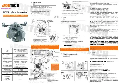
NOVA Hybrid GeneratorManual and Self-maintenance Guide V1.1Weight重量4.0kg(8.8lb)w/o Accessories/5.2kg(11.5lb)Total4kg 不含配件/5.2kg 总重量Generated Output功率1.8kW Continuous/2.0kW Max.Power1.8KW 持续功率/2KW 最大功率Dimension(L x W x H)尺寸(L x W x H )260x 312x 325mm/10x 12x 12in Applicable UAV Types适用机型Multicopters &VTOL Fix-wings多轴旋翼、垂直起降固定翼Max.Take-off Weight适用机型最大起飞重量18kg for Quadcopter 21kg for Hexacopter四轴建议18kg ,六轴建议21kgOutput Voltage适用机型动力电压12S (49V)12S (49V)Fuel Consumption油耗560g/kw ·h (hovering 1.5L/h )560g/kw ·h (悬停1.5升/小时)Service Temperature使用温度环境-20~40°C Altitude使用升限(海拔)2000m1.InstallationInstalling NOVA to UAV,default is lifted way.将NOVA 安装至无人机的合适位置,默认为吊装。
①Firstly mount the fuel tank under drone frame.首先吊装油箱总成。
②Secondly install NOVA under the tank.然后安装发电机。
Unit:mm 单位:mmDefault mounting method is in the lifted way.Other mounting methods may lead to damper failure.出厂默认为吊装,其他安装方式会导致减震器损坏。
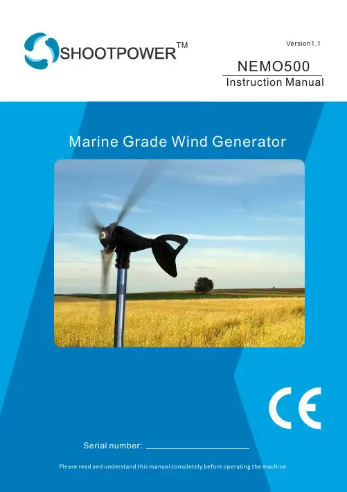
Instruction Manual NEMO500Version1.1 TM1. I ntroduction:This manual contains installation and safety information for the Nemo500 Wind turbine. The information in this manual is believed to be accurate and reliable; however,The Distributor assumes no responsibility for inaccuracies or omissions. Our company reserves the right to make changes to this product specification, or its manual, without prior notice. Therefore, check the Shoot Power Website for updates as necessary.The wind turbine, like other sources of electrical power, must be installed following the guidelines established by state and local regulations. Consult a local electrician or local planning and zoning offices for detailed information about your area.For your ease write the serial number of your wind turbine on the front of this manual. Store your manual and receipt together. You will need this information in the event of a warranty claim.CONGRATULATIONS!You will find your new wind turbine easy to install. However, it is important that you read this manual thoroughly prior to installation to assure proper performance and safety.If you have any questions after reading the manual, please contact the Distributor.2TABLE OF CONTENTS3. WIRING AND INSTALLATION PROCEDURES3.1 System wiring diagrams4.LOCATION SELECTION5. TOWER6.1 SINGLE WIND GENERATOR6.2CONTROLLER WIRING6.3 INSTALLATION OPERATION6.4 ATTACHING TO POLE6.5 STEP-BY-STEP INSTRUCTION7. WARRANTY POLICY7.1 ELEVATION8. SPECIFICATIONS 4 4 4 456 6789 10 1111 12 15 15 161. PRECAUTIONSThe wind turbine has been designed with your safety in mind. However,there are inherent dangers involved with any electrical and/or mechanicalequipment. Safety must be your primary concern as you plan the location,installation and operation of the turbine. At all times be aware of electrical,mechanical and rotor blade hazards.1.1 MECHANICAL HAZARDRotating blades present the most serious hazard. The rotor blades are made of very strong thermoplastic. At the tip, the blades may be moving at velocities over 275 miles per hour (440 km/hr). At this speed, the tip of a blade is nearly invisible and can cause serious injury. Under no circumstances should you install the turbine where a person could come in contact with moving rotor blades. DO NOT INSTALL THE TURBINEWHERE ANYONE CAN APPROACH THE PATH OF THE BLADES.1.2 ELECTRICAL HAZARDS*Observe all manufacturers' safety procedures when working around batteries andother electrical equipment.The wind turbine is equipped with sophisticated electronics designed to provide protection from high surge electrical dangers. The internal electronics of the wind turbine prevents open circuit voltages from rising above 20 volts for 12-volt systems. Please note that the inherent personal dangers from electrical current still exist, therefore caution should always be used when connecting this and other electrical devices.Heat in wiring systems is often a result of too much current flowing through anundersized wire or through a bad connection.Batteries can deliver a dangerous amount of current. If a short occurs in the wiringfrom the batteries, a fire can result. In order to avoid this threat, a properly sized fuseor circuit breaker is required in the lines connecting to the battery.1.3 INSTALLATION PRECAUTIONS:Installation procedures should be performed at ground level.Make sure that all batteries are disconnected throughout the installation process.Never install the AWS Wind Turbine upside down.Choose a day when the wind is calm.Connect the 2 wires coming from the Wind Turbine to the control switch panel. Then, connect control panel output wires to the battery bank.From Wind turbine and swtich panel has two wires(Black = Negative (-)Red = positive (+)) ensuring they do not made a mistake.1.4 OPERATION PRECAUTIONSCheck support structures, blades, and electrical systems regularly. The rotor blades are very strong; however, if they come in contact with a solid object, they can break. When performing periodic inspections, or if you must approach the path of the blades, disconnect the power leads from the battery and tie the wind turbine output leadstogether to stop /slow down the blades from rotating.Note: There is a short break-in period with new wind turbines. The bearings in both theturbine yaw and the turbine rotor will require approximately 60-100 hours of operation in normal wind speeds (approximately 18 – 20 mph, 8 – 9 m/s) before they are running at peak efficiency. During this break-in period, the turbine operation might appear sluggish.2. PACKAGE CONTENTSROTOR BLADES ARE SHARP. PLEASE HANDLE WITH CARE. USE CHART BELOW TO COMPARE PARTS.1. N ose Cone2. S crew Socket Head3. N ut-Jam-SAE 5/8-184. B lade5. H UB6. N ut-Nylock-SAE 6-327. S crew Socket head 10-24 x 1-1/2”8. F ace Assembly 10. Rotor11. O-Ring12. Body Assembly13. Snap Ring- 32 MM External 14. Yaw Shaft Assembly15. Internal MPPT Controller 16. Power Meter box63. WIRING AND INSTALLATION PROCEDURESYour Wind Turbine is shipped partially assembled. Please completely readall procedures before beginning installation. NOTE: Do not install the blade/hub until the turbine is mounted on the tower4mm hex key wrench (included)5mm hex key wrench (included)8mm hex key wrench (included)Power cables (not included):#12 AWG (American Wire Gage) stranded.Batteries (not included)Steel Pipe: 1 1/2", Schedule 40 steel pipe (Actual OD 1.875 inches, 48mm) (not included)Torque wrench with 4mm, 5mm, and 8mm hex drives (not included)Soldering iron or propane torch (not included)Rosin core solder (not included)Electrical tape or 1/4” (6-7mm) heat shrink (not included)Wire strippers (not included)Wire crimpers (not included)NOTE: Do not connect to the battery.Precheckand negative wires. With the wiresmore difficult to rotate. With the wires disconnected, it should spin freely.Every time connect the DCOUTPUT's wires (RED= Positive, BLACK = Negative)directly to the set of posts of thelighten to indicate that the controller is running properly.EVEN A SECOND, OR ELSE WILL DAMAGE THE WIND GENERATOR'S CONTROLLER AND VOID YOUR WARRANTY.4. LOCATION SELECTIONTo ensure good performance from the Wind Generator, it is important thatcare is taken in the site of the machine. Buildings, trees and rocky outcrops etc. disrupt the smooth flow of wind creating a “Wind Shear” with the wind velocity nearer the ground being slower than that higher up. Turbulence isalso created by these obstructions. Turbulence is detrimental as the swirlingair causes the Wind Generator to yaw continually thus stressing the mechanical parts and greatly increasing wear and tear.Sharp edgesCreate turbulence2H20HTurbulent airflow created by obstructions (Ad. P. Gipe, 93) Therefore, as a general rule the Wind Generator should be mounted twice as high as any such obstructions. The power obtained from the wind is proportional the cube of the wind speed, and the wind speed increases with height from the ground. A 26% increase in wind speed from a higher tower will yield a 100% increase in power from the wind generator. A little more money spent on a higher tower will harvest the same power as 2 machines! Preference should be given to the prevailing wind direction, but it should be noted that tall features behind the Wind Generator can also slow down the wind flow through the Wind Generator.7The Wind Generator should be mounted on a tower a minimum of 25'(8 meters) above any surrounding objects within a 500' (150m) radius.If this is not possible, then place it as high as you can. If this is a rooftop installation, it is important there are no objects around the structure that may block the wind.5. TOWERGreat care should be taken in the selection and preparation of the wind generator's tower, as this is the most difficult and crucial aspect of the entire installation. If you select a tower from another source or build your own, you are responsible for assuring the tower is suitable. As with all towers, you must first evaluate your site to determine the appropriate tower height, available space and reasonable cost.The following list considerations must be consulted:Number of Wind GeneratorsBudgetType: guyed, freestanding or rooftopSite: hills, trees, buildingsEase of useNote: Guyed And Freestanding Towers Are The Most Common Way To Install A Wind Generator. These Towers Are Available In All Shapes, Sizes And Costs. Caution: Do Not Install The Wind Generator Where The Path Of TheBlades Can Be Reached During Normal Operation! Never ApproachThe Wind Generator During Operation!Usually, the higher tower is erected, the greater the output, but also the greater cost and effort of the installation. If purchasing a taller tower will provide significantly more power it might offset the additional cost and effort. It's very important to mount the wind generator in the best winds while being balanced by the cost and effort of the installation.This Wind Generator is designed to use steel pipe 1.875 inch (48mm) outside diameter, equivalent to 1 ½ inch SCH 40 pipe, which can be usedin some tower applications. If larger pipe is used for your tower, makesure that the 1.875 inch pipe is at least 22 inch long or will damage the blades. Refer to SPHERE OF OPERATION (Minimum Safe Pole Length Above Obstructions).CAUTION: SAFETY, ENGINEERING AND LOCAL CODES MUST BE ADDRESSED BEFORE ATTEMPTING ANY INSTALLATION.NOTE: The yaw wires can support loads up to a total of 155 lbs. (70kg). If the wire weight is higher, you must install a strain relief to minimize the stress put on the hanging wires.NOTE: Towers must be capable of withstanding 155 lb. (70kg) of load in the horizontal direction at the Wind Generator.86.1. Single wind generatorGenerator Mode Lamp Status CauseNormal mode Stop mode Solid GreenFlashing redCharging wind speed3.13m/s to 9m/sRotor ro ta ting at lowspin or stopRotor ro ta ting at lowspin or stopFlashing red andgreen lightalternativelyThe alternatortemperatureexceeded 90C ortemperature sensordamageRotor rotating at0-1000rpmNormal mode Flashing green Charging windspeed to 9m/s to16m/sRotor rotating at1000rpm to 1500rpmSystem returns tonormal mode if thebattery voltagedrops below 13.1V,24V system 26.2VNormal ModeBattery fully charged(voltage exceeds 14.1V)or 24V system 28.2VNormallyNormallyOperationSystem returns to normal mode if the control temperature drops below 60CStop mode Solid red Rotor ro ta ting at lowspin or stopThe output is reach peakpower.It will stop 30minsand restart again9106.2 CONTROLLER WIRINGDo not make a wrong positive and negative connections to the power meter box or the battery bank.The wrong positive and negative connection or positive and negative in short circuit condition will damage the power meter box or wind turbine controller, the warranty will not cover.Black is for negative.When the green light is on or flashing, it is normal charging.Please connect with power meter box in any time, without power meter box positive and negative direct short circuit easily damaged internal controller in wind condition, the warranty will not covered.The power meter box main function is display and break the wind turbine, theMPPT controller in the wind turbine body.B”+” is battery”+”B”-” is battery”-”Wind”+” is Wind turbine”+” ; Wind”-” is Wind turbine”-” ;ImportantUse bolt driver to remove the 4pcs screws on the backside of the meter box and open it, then install the cables from the wind turbine and battery to the power meter box board as the following photo:For more information about some very economical tower kits for thewind generator, please refer or purchase them from your dealer or distributor.6.3 INSTALLATION OPERATIONChoose a calm day and have someone available to help during the installation process.NOTE: THE BLADE EDGES ARE SHARP. PLEASE HANDLE IT CAREFULLY. NOTE: DO NOT install the blade assembly until the body is mounted onthe tower.CAUTION: ALL BATTERIES MUST DISCONNECTED THROUGHOUTTHE INSTALLATION PROCESS!CAUTION: DO NOT INSTALL THE WIND GENERATOR WHERE THEPATH OF THE BLADES CAN BE REACHED DURING NORMAL OPERATION! NEVER APPROACH THE WIND GENERATOR DURING OPERATION!USE COMMON SENSE AND PLEASE BE CAREFUL!6.4 Attaching to poleRight Right WrongFigure 3 Proper Blade-to-Tower Clearances6.5 Step-by-step instructionsoutline of the Marine grade Nemo500 wind turbine installation process. This consolidated reference should only be used as an outline during installation. Refer to the appropriate sections for further details.1).Ensure the voltage systems of the wind generator and the battery bank are the same. Prepare the appropriate wires.2).Run the wire through the pipe and drag the wires near to the batteries(Do not connect to the battery), strip the insulation back from each set of wires.b a t t e r y3).Connect the Wind Generator to the wires and insulate the connections using either heat shrink tubing or a quality electrical tape.4).Once the yaw shaft is on the tower, firmly tighten the yaw clamp screws with the 4mm hex key to 3-5 foot pounds(4.0-6.5Nm). Be sure that it is securely attached to the mounts.Slide the yaw shaft all the way down over the end of pole being careful not to pinch the yaw wires. Be sure to leave enough slack in the wires so that if necessary, the Wind Generator can be removed.5) Prepare a grounding cable from yaw shaft screw, secure the grounding cable against the pipe with insulation tape for grounding the windgenerator by the pipe.6).Place one of the blades on the hub socket and insert one of the M6-15socket head cap screws. Place a plastic disk on the end of the screw, then place self-locking nut (M6) and tighten it with the 5mm hex key to 8-107). Remove the M16 nut from the rotor shaft. Slide the blades assembly ontothe blades assembly. Holding the blades assembly and tightening the M16nut lightly with the 8mm hex key. Finally, spin the blades slowly to be sure they turn freely.8mm Hex KeyCAUTION: DO NOT SCREW M16 NUT TOO TIGHTLY, OTHERWISE THE FACE BEARING WILL BE STUCK AND THE BLADES ROTATE DIFFICULTLY!9) Place the nose cone over the center line of the blades assembly and snap the nose cone into place. Carefully check it is secure by firmly pulling on and be sure all three edges are catch. Don't worry if the nose cone missing, it will not affect the performance of the wind generator.Nose Cone9)Before attaching the wiring to the battery, make sure that:a.All wires connect to the control box and battery ok.b.The stop switch is in the "Stop"position.Note: GroundingFor long-term operation and protecting the electronics, properly grounding is very important. Grounding procedures must be followed along with any local electrical codes.The negative wire of your system should be connected to a ground. This is usually done by connecting a wire from the negative battery terminal to a nearby ground rod. Wires with the same ratings as the positive andnegative wires must connect all system grounds.A ground electrode can be made for systems without an existing systemground from an 8 ft. (2.4 m) section of 3/4" (19 mm) galvanized pipe orconduit, or an 8 ft. (2.4 m) section of 5/8" (16 mm) iron or steel rod. Thisground electrode must be buried completely beneath the soil, at no more than 45 degrees from vertical, or horizontally at least 2 1/2 ft. (75 cm)beneath the surface. It is recommended that the ground electrode beinstalled as close as possible to the batteries for maximum lightningprotection. The base of the tower is also a good location for anappropriate surge arrestor.Caution: Improper Grounding Will Damage Your Wind GeneratorAnd Void Your Warranty.10)Carefully raise the tower and secure base and/or guy cables.Caution: Ensure That The Tower Is Vertical So That The WindGenerator Can Yaw (turn Into The Wind) Properly.CONGRATULATIONS! You have completed the installation process now.FEET1-500ftMETER 0-150m OUTPUT POWER 100%500-1,000ft1,000-2,000ft2,000-3,000ft3,000-4,000ft4,000-5,000ft 5,000-6,000ft6,000-7,000ft7,000-8,000ft8,000-9,000ft9,000-10,000ft 150-300m 300-600m 600-900m 900-1,200m 1,200-1,500m 1,500-1,800m 1,800-2,100m 2,100-2,400m 2,400-2,700m 2,700-3,000m 97%94%91%88%85%82%79%76%73%70%7.1 ELEVATIONAn important fact to keep in mind is elevation. The higher a Wind Generator is from sea level, the lower the air density. Air density is directlyproportional to the output of your Wind Generator. Here are somegeneral numbers to keep in mind when determine the maximum output that can be expected from a Wind Generator.7. Warranty policy proof of purchase is required(Receipt)Our company wind turbineour companyother obligations in connection to our company and it products. Any impliedOur company8. SPECIFICATIONSTMShoot Power Equipment Co., LtdMade In China。
目录Cataloge第一部分The first part (1)一、概述:outline (2)二、机组技术参数:the unit technical parameter (2)三、结构组成:the structure composes (3)四、开箱检查:open the case and check out (4)五、选择安装地点choose installation site (5)六、地基施工指导the ground construction instruct (5)七、机组安装:install the unit (6)八、注意事项: attention matters (8)九、日常维护routine maintenance (9)十、故障排除trouble shooting (9)十一、产品保修Warranty (10)第二部分 The Second part 使用说明书Operating instruction manual (11)第一部分The first part感谢您购买“日普昇”牌RPS系列小型风力发电机,安装使用前,请仔细阅读本用户使用手册,有助于保证产品的安全、正常运行并充分发挥其优越性能。
愿您尽情享受RPS系列风力发电机带给您的光明与快乐!本手册内所指风机即为RPS系列小型风力发电机。
Thank you for buying the RPS series of small wind power generations , before you using it, please read the users manual serious, it is helpful in the guarantee productsecurity、the normal operation and displays its high performance fully. Hope you can enjoy the bright and happy taking by the RPS series wind power generations.一、概述:outline风力发电机,是一种将风能转变为机械能,再转变为电能的机电设备,利用风力发电,向蓄电池充电蓄存电能,还可以把蓄存的电能转变为220V(380V)/50HZ 的交流电源,风力发电不需燃料,无污染、无噪音。
INSTALLATION,SERVICE&MAINTENANCE MANUAL 安装使用及维护手册FOR THREE-PHASE SYNCHRONOUS GENERATOR MODELS三相同步发电机1安全措施敬请各位用户在使用前务必仔细阅读和理解本手册中有关发电机安装调试、使用和维护的内容。
正确的操作和保养才能保证设备安全、有效的运行。
很多事故的发生都是由于未按操作要求,未做好保护措施而造成的。
警示标识本手册中使用和随发电机提供的警示和警告标识的含义如下,发电机组制造商应确保警示标签位置放置正确并清晰,标签含义如下:普通警告标识,可能会导致人员伤亡、设备损坏的危险电气危险标识,可能电气原因会导致人员伤亡的直接危险通用危险标识,可能会导致人员伤亡的直接危险遵守所有警告或告诫牌上的提示。
★确保安装符合所有适用的安全标准和地方电气标准,所有安装操作要由有电工操作证的人员来实施。
★开机运行前一定要检查防护网、盖板、线盒盖等是否装到位。
★在维护和保养过程中,切断与电网或其它发电机组间的闭合回路,并在断开的开关上挂置警告牌,以免发生意外的线路闭合。
友情提示:由于本公司产品技术在不断的提高,本手册中内容在印制时都是正确的,但随时都会有改进和修正。
不正确的安装、操作和维护,私自更换零部件会导致严重的人员事故、设备损坏。
操作和维护人员必须具有电气和机械维护资格。
前言本手册的功能是为了让用户了解德科电气三相同步发电机的工作原理、发电机的设计标准及产品安装和维护步骤及要求。
缺乏应有保护或安装、使用步骤不当等都会引起设备的损坏,同时还会有可能造成人员伤害的安全事故发生。
说明书中的特别区域会用警示牌进行标记。
德科电气公司建议用户要在进行安装或使用发电机前仔细阅读并理解本手册的内容是非常有必要的。
如有疑问,请随时同我们沟通,德科电气科技有限公司的销售和技术团队愿随时提供支持,并欢迎来公司垂询。
2目录安全措施 (1)前言 (2)目录 (3)1简介 (5)1.1标准 (5)1.2发电机型号定义 (5)1.3产品序列号位置 (5)1.4铭牌 (5)2发电机的应用 (5)2.1使用环境 (5)2.2发电机的容量修正 (6)3发电机工作原理 (6)3.1自励AVR控制的发电机 (6)3.2永磁发电机(PMG)励磁AVR控制的发电机 (7)3.3AVR其它说明 (7)4发电机结构 (8)4.1定子(MAIN STATOR) (8)4.2转子(MAIN ROTOR) (8)4.3励磁系统(EXCITATION SYSTEM) (9)4.3.1励磁机定子 (9)34.3.2励磁机转子 (9)4.3.3旋转整流桥 (9)4.3.4自动电压调节器(AVR) (9)5安装 (14)5.1起吊 (14)5.2安装环境 (15)5.3安装 (15)5.3.1单轴承发电机安装 (16)5.3.2双轴承发电机安装 (16)5.4发电机旋转方向 (16)5.5接线 (17)5.5.1发电机为50Hz时不同电压的接线 (17)5.5.2发电机为60Hz时不同电压的接线 (18)5.6接地、保护 (19)6运行 (20)6.1运行前的检查 (20)6.2运行前的试验调整 (21)6.3开机与停机 (22)7维护和检修 (22)7.1一般维护 (22)7.2检修项目 (22)7.2.1绕组绝缘电阻的检测 (22)47.2.2.轴承检查 (23)7.2.3通风检查 (23)7.2.4直流电阻检查 (23)7.2.5AVR检查 (24)7.2.6同心度检查 (24)7.2.7其它检查 (24)7.3发电机的拆装 (24)7.3.1拆卸步骤 (24)7.3.2装配步骤 (25)7.3.3拆装注意事项 (25)7.4现象及排除 (25)7.5AVR故障检修 (27)8产品接收、检查及存储 (27)9发电机结构图及部件明细表 (27)10服务 (29)51简介TCU系列无刷三相同步发电机(以下简称发电机)为无刷励磁、旋转磁场结构的交流发电机。
电机安装与维护的英语作文Electric Motor Installation and Maintenance。
Electric motors are an essential part of manyindustrial and commercial processes. They are used to power everything from pumps and fans to conveyor belts and manufacturing equipment. Proper installation and maintenance of electric motors is crucial to ensuring their longevity and optimal performance.Installation。
When installing an electric motor, it is important to follow the manufacturer's instructions carefully. This will help ensure that the motor is installed correctly and that it operates as intended. Here are some general guidelines to keep in mind:1. Mount the motor securely: The motor should be mounted on a solid base or frame. This will help reducevibration and ensure that the motor operates smoothly.2. Align the motor properly: The motor shaft should be aligned with the driven equipment shaft. Misalignment can cause excessive wear and tear on the motor and the driven equipment.3. Connect the wiring correctly: The wiring should be connected according to the manufacturer's instructions. This will help ensure that the motor operates safely and efficiently.4. Check the motor's rotation: The motor should be checked to ensure that it is rotating in the correct direction. This can be done by observing the rotation of the shaft or by using a rotation detector.Maintenance。
Application Guidance Notes: Technical Information from Cummins Generator Technologies AGN 030 – Service and MaintenanceDESCRIPTIONSuitable service and maintenance are vital to the reliable operation of the alternator and the safety of anyone coming into contact with the alternator. The alternator should be inspected between scheduled maintenance, in line with inspection procedures and schedules provided by the manufacturer to identify any potential failure modes, signs of misuse or excessive wear and tear.An alternator specific Owner’s Manual (also known as Installation, Service and Maintenance Manual) is supplied with every alternator. The manuals are also published on the website. Each manual includes a Section on Service and Maintenance.The service activities are intended to maximise the life of the alternator but shall not vary, extend or change the terms of the manufacturer’s standard warranty or the customer’s obligation in that warranty.Each service interval is a guide only, developed on the basis that the alternator was installed and is operated in accordance with the manufacturer’s guidelines. If the alternator is located and/or operated in adverse or unusual environmental conditions, the service intervals may need to be more frequent. The alternator should be continually monitored between services to identify any potential failure modes, signs of misuse or excessive wear and tear. Recommended Service ScheduleThe recommended service schedule published in the manual shows the recommended service activities in table rows, grouped by alternator subsystem. Columns of the table show the typesof service activity, whether the alternator must be running, and the service levels. Service frequency is given in running hours or interval time, whichever is sooner. A cross (X) in the cells where a row intersects the column shows a service activity type and when it is required. An asterisk (*) shows a service activity done only when necessary.Service level documents referred to in the recommended service schedules can be purchased directly from Cummins Generator Technologies Customer Service Department, by telephone on +44 1780 484732 or by email: **************************************************. STAMFORD AlternatorsThe recommended service schedule for STAMFORD alternators can be found in Section 7 of the manual, with the following breakdown of sub-sections:Recommended Service ScheduleBearingsControlsCooling SystemCouplingRectifier SystemTemperature SensorsWindings.AvK AlternatorsThe recommended service schedule for AvK alternators can be found in Section 10 of the manual, with the following breakdown of sub-sections:Preventive ServicingSafety PrecautionsRecommended Service ScheduleServicing – General StructureVibrationServicing the Bearings and the Lubrication SystemGenerators with Bearing InsulationService WindingsServicing the Generators CoolerRepairs, Dismantling and Reassembly.Importance of Alternator MaintenanceThe maintenance programme is developed to meet the needs of different alternator designs. There are three types of maintenance strategies;∙Reactive maintenanceo Failure or abnormal operation.∙Preventive time based maintenanceo Time based maintenance.o Based on manufacturer’s experience.Predictive / condition based maintenanceo Maintenance based on actual measurements.A regular preventive maintenance schedule will ensure peak performance, maximize alternator life, maximized reliability and minimize breakdowns.INSTALLATION CONSIDERATIONSThe alternator must be installed in an accessible location with easy access to the main terminal box, bearing cap, air filter, louvers (inlet and outlet) and NDE/DE end brackets. The mentioned access points provide easy access to internal alternator components as shown in Figure 1. This will allow the execution of periodic inspections, local maintenance and removal of the alternator for external services.Figure 1: Internal alternator components that require periodic maintenance. Alternators LiftingDifferent alternator designs must be lifted by hooks or shackles attached to the lifting points (lugs or eyes). Chains of sufficient length, and a spreader bar if necessary must be used when lifting the alternators so as not to damage the terminal box, alternator parts and prevent the rotor from failing out on 1 bearing alternators as shown in Figure 2. When lifting entire Generating Set, the installation engineer must use specially designed Generating Set lifting points, and not alternator lifting lugs.Figure 2: Showing an example of the right and wrong alternator lifting methods. Mechanical CouplingInstallation engineers should follow the alternator manufacturer’s integration instructions provided in the Owner’s Manual. When coupling, the engineer should not attempt to rotate the alternator rotor by levering against the vanes of the cooling fan as shown in Figure 3 as the fan is not designed to withstand such forces and will be damaged. The holes of the coupling discs should be aligned with the flywheel holes by cranking the engine. Additional forces should not be put on the bearings while assembling the coupling half as it will damage the bearings.Figure 3: Alternator cooling fan vanes.SafetyIt is important to follow the alternator manufacturer’s general and local health and safety instructions. Incorrect installation, service or replacement of parts can result in severe equipment damage and personal injury. Only qualified individuals should perform electrical and mechanical component installations. Safety information signs are provided on the equipment to indicate hazards and emphasize instructions.Figure 4: Examples of the safety signs provided on an alternator. Environmental ConditionsAlternators installed in Generating Sets that are sited in arduous ambient environmental conditions may be susceptible to breakdown at their location site, if appropriate service and maintenance is not carried out. Ensuring reliable satisfactory service though, starts with careful consideration being given to the design of the ventilation systems that will be shared by both alternator and engine. Simplifying the considerations to just deciding to have a relatively simple canopy with large openings for the benefit of the engine and then considering the alternator satisfied by the fitting of low cost air filters will result in operating problems.Decisions at the Generating Set design stage about the Canopy design and airflow control must include discussions with the alternator manufacturer to ensure that the appropriate optional extra air-filter / louver kit is nominated or the IP rating of the alternator is increased and that a bespoke maintenance regime is implemented for the complete Generating Set.Refer to AGN072 – Environmental Conditions, for guidance on appropriate installation from the alternator manufacturer’s viewpoint.Alternators in Coastal LocationsFor example; an RTG Crane application is a quite unique situation. For reasons of making the alternator output characteristics suitable to power the Crane’s drive motor, combined with the duty cycle of the variable crane motor load, the alternator is usually operating with quite low winding temperatures. Whilst this low temperature situation would normally be considered to be beneficial, it does introduce a problem when the operating environment is a salt laden with a high humidity. The accepted winding temperature at which moisture is driven from the windings is some 95o C and experience is showing that RTG applications do not achieve this. So we have a winding contaminated by a salt laden atmosphere, combined with the dust and pollutants around a working dockside, plus RIC engined port vehicles adding exhaust by-products to this winding contamination problem. Add to this the humidity and moisture associated with local weather conditions, forming surface moisture on the alternator’s outhang, a winding that is not getting hot enough to drive the moisture off and we have created a winding insulation system with much reduced ‘barrier’ capabilities.The above considers the contaminants that weaken the winding insulation system. The following explains the additional electrical stresses associated with the Variable Speed Drive units used to power the various crane movements.These VSD’s are Non Linear Loads [NLL], with quite high levels of harmonic distortion. The resulting harmonic voltage distortion results in transient voltage conditions that may well be twice the peak value that the alternator would experience under normal linear load conditions.These high transient voltage spikes stress the electrical insulation system, with which a clean uncontaminated winding insulation system can cope. But a contaminated winding will find such transient voltage spikes difficult to contain, followed inevitable by the breakdown of the insulation barrier and winding short circuit.The decision to have the new alternator fitted with IP44 inlet louvers will ensure that whilst the alternator is running, the inlet cooling air is being filtered and moisture droplets are being removed by the Premaberg filter system.However the IP44 filter assembly is not really addressing all the problems of the location being in a coastal, salt laden atmosphere. The problem with salt is that it will form a moisture absorbing film of contamination on the alternator’s winding. When the alternator is working and the windings are hot, the moisture is driven off the windings surface and the insulation resistance - IR - will be high enough to ensure that no insulation breakdown or surface tracking occurs. However; as soon as the Generating Set is stopped, the alternator’s local environment becomes extremely humid, it is at this point the hygroscopic layer of salt that has formed on the windings will absorb moisture and this will result in the windings IR value being reduced to a low level and so, an inability to insulate/isolate phase to phase and phase to earth. Therefore, when the Generating Set is next started and the alternator excites to the normal working voltage - electrical pressure - there is a real risk that an insulation failure will occur as a result of insulation breakdown initiated by surface tracking.The ideal solution is to filter the salt from Generating Set cooling air. But the practicalities must include control of the humidity level of the alternator’s environment and this involves far more than the fitting of an alternator anti-condensation heater.The most successful schemes involve a fan heater bl owing several kW’s of hot air around the Generating Set ‘chamber’ to keep the humidity RH% as low as possible. Obviously, this needs an electrical power supply when the Generating Set is not running and so may well not be an easy option.There may be a way of running-on the Generating Set after its programmed service duty. This would be in a way devised to keep hot dry air circulating whilst the whole Generating Set area temperature is gradually reduced to stop the sudden increase in RH% that occurs around Generating S ets when they are stopped and left trapped in their ‘sweat box’ canopies.It could be that Generating Set’s are operating in parallel, or a Generating Set is operating in parallel with a mains supply. This then suggests an option to introduce some Generating Set environment control, because it would seem that there is always an electrical supply available. We cannot rule out that the stresses associated with miss-paralleling, or the instability of the local mains supply e.g.; micro-interruptions, will damage insulation systems and promote failures. But if the site history is one of winding failures occurring at the point/moment of starting the Generating Set ready to put the unit back into service then, from experience, we would consider saline contamination is the prime culprit.MAINTENANCE OF THE WINDING INSULATION SYSTEMThe only way to check on the condition of the winding insulation system, is by introducing a regular procedure to check the stator winding Insulation Resistance (IR) value and although not normal practice for a low voltage scheme, the Polarisation Index [PI] should be measured too, if the alternator is installed in any challenging environment. This check of IR and PI need only be carried out to the stator winding. The spinning of the rotor and the fact that it operates at low voltages means that it is not, as much, at risk.Refer to AGN015 – Testing Winding Insulation Systems for details of IR and PI testing.At the first sign that the IR and PI are low, the alternator stator winding must be cleaned.T he exciter field is another ‘at risk’ component and the fact that it operates with dc. means that it has a high risk factor due to its operation with fixed polarisation. If the exciter field insulation fails it will also take out the AVR.Cleaning windingsIf cleaning of the windings becomes necessary, then the preferred method is to completely strip the alternator to enable a thorough inspection and then a washing process, which will result in dirt removal by encouraging a washing-out of dirt by an action that will not result in the dirt being forced further into the winding assembly. The washing medium should be clean hot water applied from a directional nozzle at a pressure not exceeding 3bar.At no point should the winding insulation be subjected to a jet of water pressure that is deforming the insulation materials.For extremely oily contaminants, an alternative method is to use a hot pressure wash - not exceeding 3bar – with an added solvent based biodegradable cleaner of neutral pH. Note: ‘Autosmart’ and Aquawash’ are trade names of such biodegradable cleaners.Water-based Alkaline Detergents should not be used for cleaning as they contain ‘wetting agents’ that leave contaminants - in the form of salts - on the winding surfaces. These contaminants are hygroscopic and therefore readily absorb moisture, which will lower the insulation resistance and promote surface tracking.Caution: Inappropriate or badly executed cleaning methods will leave contamination embedded in the winding crevices and this local contamination will promote degradation of the insulation system.After the cleaning process, the windings must be slowly[over several hours] heated to at least 100degC in a thorough drying out procedure of perhaps twelve to twenty four hours. The insulation resistance [IR], phase to phase, and phase to earth, must be measured during this process.Refer to the alternator’s Owner’s Manual (Installation, Service & Maintenance Manual) for the drying out procedures and the IR test procedure, including the values, in Mega-Ohms, that thewinding must achieve before the winding IR can be said to be high enough for the wound assembly to be considered a serviceable unit.Once the windings have been cleaned and the insulation resistance improved to what is considered to be a satisfactory level, the clean and dry windings should be treated with an appropriate ‘over-coating’ electrical anti-tracking resin / varnish. This treatment will offer protection from further immediate in-service recontamination of the winding surface. The chosen anti-tracking material should be of the same insulation thermal rating as the alternator’s insulation system - Class ‘F’ or Class ‘H’.Checks must also be made to ensure that the electrical anti-tracking resin / varnish will adhere to the windings original impregnation materials.Application Guidance Notes are for information purposes only. Cummins Generator Technologies reserves the right to change the contents of Application Guidance Notes without notice and shall not be held responsible for any subsequent claims in relation to the content.。
© 2008 American Honda Motor Co., Inc.— All Rights Reserved Page 1 of 6First Issue Date: December 2008PTB54072 (TO132.2008.12)CONSUMER INFORMATION: The information in this service bulletin is intended for use only by skilled technicians who have theproper tools, equipment, and training to correctly and safely service and repair your Honda power equipment. These procedures should not be attempted by “do-it-yourselfers,” and you should not assume that this bulletin applies to your equipment, or that your equipment has thecondition described. To determine whether this information applies, contact an authorized Honda Power Equipment dealer.GENERATOR #40DECEMBER 2008EU1000i • EU2000i ENGINE WILL NOT STARTSYMPTOMThe engine will not start because there is no spark.The engine stop switch may have collected dust or debris that prevents the switch from working properly.In rare cases, the engine may not stop when the engine stop switch is in the OFF position. The engine will continue to run until the carburetor runs out of fuel.AFFECTED UNITSCORRECTIVE ACTIONThis bulletin addresses engine stop switch failures thatproduce the symptom "engine will not start because there is no spark."The symptom may also be caused by the following:•Ignition system •Oil Alert® systemTroubleshoot the engine stop switch starting on the page shown for your model.EU1000i - page 2EU2000i - page 4If troubleshooting confirms the engine stop switch is good, use the appropriate shop manual to test the ignition and Oil Alert® systems.If troubleshooting confirms the engine stop switch is bad, install a new engine stop switch.A new engine stop switch is available that provides a better seal to help prevent dirt and debris entering the switch.The new engine stop switch can be identified by the round plunger instead of the square plunger on the old switch.EU1000i EZGA-1000001 ~ 1210647EU2000iEAAJ-1000001 ~ 1822406NEW-STYLE ENGINE STOP SWITCHDust or debris may cause the engine stopswitch to fail and not allow the engine to start.OLD-STYLE ENGINE STOP SWITCHSQUARE PLUNGERROUND PLUNGERPage 2 of 6© 2008 American Honda Motor Co., Inc.— All Rights ReservedPTB54072 (TO132.2008.12)GENERATOR #40DECEMBER 2008TROUBLESHOOTING PROCEDURE• EU1000i1.Turn the engine stop switch to theON position. With the generator on a level surface, pull the starter grip and check the Oil Alert® indicator.Flashing – add oil to bring the level to the upper limit. If still flashing after adding oil, proceed to step 6.Not flashing – proceed to step 2.2.Remove the maintenance cover.3.Drain the fuel tank and the carburetor float bowl into anapproved container.4.Remove the spark plug and pull the starter grip severaltimes to remove any unburned fuel from the combustion chamber.5.Insert a new spark plug in the spark plug cap andcheck for spark as shown.•Spark – the problem was the spark plug. Proceed to step 20.•No Spark – continue to step 6.6.Remove the two 5 x 20 mm screws.7.Remove the four front cover screws and the frontcover.8.Pull the control panel away from the generator.9.Disconnect the yellow oil level switch wire frombehind the control panel and recheck for spark.•Spark – the problem is the oil level switch. Replace the oil level switch following the shop manual procedure.•No Spark – proceed to step10.UPPER LIMITOIL ALERT ®INDICATOR5 x 20 mm SCREW (2)CONTROL PANELFRONT COVERFRONT COVER SCREW (4)YELLOW OIL LEVEL SWITCH WIRES© 2008 American Honda Motor Co., Inc.— All Rights ReservedPage 3 of 6PTB54072 (TO132.2008.12)GENERATOR #40DECEMBER 200810.Remove the four 5 x 16 mm washer screws and the muffler protector.11.Remove the following:•Fuel cap•Lift the neck seal and remove the 10 mm circlip •Two 6 x 100 mm screws and 6 mm washers •Two 6 x 20 mm screw-washers• 5 x 10 mm screw-washer that secures the recoil guide to the engine12. Lay the unit flat on its right side cover with the right side coverresting on a protective pad.13.Carefully separate the left side cover from the right side cover.14.Remove the fuel tube and diaphragm tube from the fuel pump.15.Disconnect the engine stop switch 2-pin connector and checkfor spark.•Spark – Proceed to step 16.•No Spark – troubleshoot the Ignition System following the shop manual procedure.16.Remove the two 3 x 16 mm self-tapping screws and theengine stop switch. Discard the engine stop switch and the harness band.17.Install the new engine stop switch and harness band. Tightenthe two 3x 16mm self-tapping screws securely. Do not over-torque. Check for spark to verify your repairs.18.Reassemble the generator.19.Add fuel and start the engine. Check for fuel leaks.20.Test the generator by performing the load bank test (see ToolOrdering Information on page 6).Maximum Output: 120V, 1.0 kVA, 8.3 Amps Rated Output: 120V, 0.9 kVA, 7.5 Amps5 x 16 mm WASHER-SCREW (4)MUFFLER PROTECTOR6 x 20 mm SCREW-WASHER (2)10 mm CIRCLIPFUEL CAPNECK SEAL6 x 100 mm SCREW (2)6 mm WASHER (2)ENGINE STOP SWITCH 2-PIN CONNECTORDIAPHRAGM TUBEFUEL TUBERECOIL GUIDE 5 x 10 mm SCREW-WASHERLEFT SIDE COVERRIGHT SIDE COVERENGINE STOP SWITCH3 x 16 mm SELF-TAPPING SCREW (2)HARNESS BANDFUEL TUBE HERE DIAPHRAGM TUBE HEREPage 4 of 6© 2008 American Honda Motor Co., Inc.— All Rights ReservedPTB54072 (TO132.2008.12)GENERATOR #40DECEMBER 2008• EU2000i1.Turn the engine stop switch tothe ON position. With the generator on a level surface, pull the starter grip. Verify the Oil Alert® indicator is not flashing.Flashing – add oil to bring the level to the upper limit. If still flashing after adding oil, troubleshoot the Oil Alert® system following the shop manual procedure.Not flashing – proceed to step 2.2.Remove the maintenance cover.3.Pinch the carburetor inlet fuel line using hosepinching pliers (available through the Honda Power Equipment Tool and Equipment program by calling (888) 424-6857) and drain the carburetor float bowl.4.Remove the spark plug and pull the starter gripseveral times to remove any unburned fuel from the combustion chamber.5.Insert a new spark plug in the spark plug cap andcheck for spark as shown.•Spark – the problem was the spark plug. Proceed to step 13.•No Spark – continue to step6.UPPER LIMITOIL ALERT ®INDICATORHOSE PINCHING PLIERS, SUN-HCP6(Commercially available)© 2008 American Honda Motor Co., Inc.— All Rights ReservedPage 5 of 6PTB54072 (TO132.2008.12)GENERATOR #40DECEMBER 20086.Locate the engine stop switch 2-pin connector(black and green wires) in the lower right side of the maintenance cover opening. Disconnectengine stop switch 2-pin connector and check for spark.•Spark – Proceed to step 7.•No Spark – troubleshoot the Ignition and Oil Alert Systems following the shop manual procedures.7.From the maintenance cover opening,disconnect the following connectors:•2-pin connector from the Eco-Throttle ® switch•8-pin connector from the ignition control module•6-pin connector from the inverter •6-pin engine harness connector8.Remove the four 6 x 15 mm special screws and slide the front cover away from the generator.9.Remove the 3 x 16 mm self-tapping screw, the 3 x 12 mm self-tapping screw, and the engine stopswitch. Discard the engine stop switch and the harness band.10.Install the new engine stop switch and harness band. Tighten the 3x 12mm and the 3x 16mm self-tapping screws securely. Do not over-torque. Check for spark to verify your repairs.11.Reassemble the generator.12.Add fuel and start the engine.13.Test the generator by performing the load bank test (see Tool Ordering Information on page 6).Maximum Output: 120V, 2.0 kVA, 16.6 Amps Rated Output: 120V, 1.6 kVA, 13.3 AmpsENGINE STOP SWITCH 2-PIN CONNECTORECO-THROTTLE 2-PIN CONNECTORIGNITION CONTROL MODULE 8-PIN CONNECTOR INVERTER6-PIN CONNECTOR ENGINE HARNESS 6-PIN CONNECTOR6 x 15 mm SPECIAL SCREW (4)FRONT COVER3 x 16 mm SELF-TAPPING SCREW3 x 12 mm SELF-TAPPING SCREWHARNESS BANDPage 6 of 6© 2008 American Honda Motor Co., Inc.— All Rights ReservedPTB54072 (TO132.2008.12)GENERATOR #40DECEMBER 2008TOOL ORDERING INFORMATIONTwo load bank test sets are available from American Honda:PARTS INFORMATIONOrder the appropriate parts through your normal parts ordering procedures.WARRANTY INFORMATIONDurationIn warrantyThe normal warranty applies.Out of warrantyAny repair performed after warranty expiration may be eligible for goodwill consideration. Contact Techline or your District Service Manager. You must request consideration and receive a decision before starting work.VIN InformationProcessingService Bulletin warranty claim submission requirements apply. After completing the Service Bulletin repair procedure, submit one warranty claim per unit with the following information:Part Number DescriptionSource06610-BCS-2612AHBCS Generator Load Bank SetAvailable through the American Honda Parts System using normal parts ordering procedures.STH-627KIT Sotcher Generator Test SetAvailable through the Honda PowerEquipment Tool and Equipment program by calling (888) 424-6857.DescriptionQty Part Number H/C Engine Stop Switch Assy.135120-ZT3-023*******Harness Band136135-ZA8-8012085512VIN Prefix Affected Serial Number RangeModelEZGA 1000001 ~ 1210647EU1000i EAAJ1000001 ~ 1822406EU2000iN Dealers:•Select Service Bulletin claim type.•Enter VIN information.•From the Service Bulletin drop down menu, select GG040 (Generator Service Bulletin #040) for appropriate model and repair.All others:Defect Code:03001Labor Operation Number:615120Flat Rate Time:0.8Failed Part:35120-ZT3-013。
1 Operation of generator1。
1 Preparations before start—up, including:a)Clean the work-yard and the generator set from any debris.b) Check the tightening condition, lock the gasket tightly,tack weld ifnecessary;keep the rotatable parts clean。
c) Check the inlet and outlet water pipelines, oil pipelines and valves,in orderto know if there are leakages and problems of water flow in the pipe.d) Check the level of lubricating oil, oil number, oil quality, water pressure,andrecord the water temperature and ambient temperature.e) Check each connecting cable, to make sure that the joints contact well andwithout rust, connection is right,and the marks are complete and distinct。
f) Check if the equipments of high—pressure oil and the brake run normally, and if the brake pressure can meet the relevant requirements。
S T C 系列STC SERIES三相交流同步发电机THREE-PHASE A.C.SYNCHRONOUS GENERATORS使用维护说明书INSTRUCTIONS FOROPERATION AND MAINTENANCE中华人民共和国上海重琦电力设备有限公司SHANGHAI ZHONGQI MOTORS CO.LTD STC SERIES 3-PHASE A.C SYNCHRONUOS GENERATORSThe generator of this series completed with a matching internal combustion engine is available as a stationary or movable power station to supply a lighting or power resource for villages,towns,working sites and pssture-lands.It is of three-phase with neutral point star connection,characterized by a line voltaga of 400V,phase voltage of 230V,frequency of 50 Hz,and power factor of 0.8(lagging).We can provide with 60 Hz and other value generators which the users are necessity.The connection of the generator to the prime mover may be made directly or by means of a triangle belt.Its rotation can be in both positive and opposite sense for continuous rated duty. In order to permit the maohine to produce current in its normal running, it is well-advised to get yourself informed from the present instruction manual beforehand.1.SPECIFICATIONS AND CHARACTERSTICS-1-In this series of generator a harmonic excitation is adopted. On the core in addition to the main winding,there is also a harmonic winding. The cerrent to be rectified, after flowing through the 3-phase bridge silicon-controlled rectifier,enters the magnetic field coil where excitation takes place.So long as the third harmonic voltage will increasecorrespondingly upon the loading of the generator, a self-excitation constant voltage characteristic is acquired and any complicated automatic voltage regulator can thus beModle OutputCurrent (A) pole number Synchronous speed (r.p.m) KVA KW STC-5-2 6.3 5 9 2 3000 STC-3 3.8 3 5.4 4 1500 STC-5 6.3 5 9 4 1500 STC-7.5 9.4 7.5 13.5 4 1500 STC-10 12.5 10 18.1 4 1800 STC-12 15 12 21.7 4 1500 STC-15 18.5 15 27.1 4 1500 STC-20 25 20 36.1 4 1500 STC-30 37.5 30 54.1 4 1500 STC-40 50 40 72.2 4 1500 STC-50 62.5 50 92.2 4 1500 STC-64 80 64 115 4 1500 STC-75 92.8 75 136 4 1500 STC-90 112.5 90 162 4 1500 STC-100 125 100 181 4 1500 STC-120 150 120 216 4 1500 STC-150 187.515027041500dispensed with.This machine possesses a superb dynamic behaviour which makes possible anoload direct-on starting of squirrel-cage asynchronous motor with similar capacity wythout additional starting device.Ⅱ.CONSTRUCTIONThe generator is of rotating-field type.Its frame and end-covers are all built of cast iron.The stator's core is made up of 0.5mm high quality silicon steel lamination,while the magnetic pole's core is made up of lmm electrical sheet stampings.High-strength enamelled wire is used as conducting wire,stator insulation is of Class E,and rotor insulation is of Class B.The outlet box is located on top of the machine frame. In the box are installed the terminal panel and silicon-controlled rectifier unit. The switch-box arc assembled on the frame of the generators. In the switchbox have been mounted connecting plate, silicon rectifier and field rheostat,with the addition of the field rheostat of 30~50KW. There are indicator of 6.3V and voltemeter on the face plate.The cotput cable is wired from outgoing line hole plate in the rear of the switch box. When it is in operation before the seated film of the outgoing line hole plate be eaposed with the pochet knife.The wiring principole chart is shown as in Fig 1.In the diagram the Z4、Z5and Z6、Z7as for the elementary wave coil of the auxilliary winding of the difference turns .Both ca nreach to adjust unloaded voltage purpose via change over right and reverse series connecting plate.The unloaded voltage rises when the Z4、Z6connect to the Z7、Z8. when the Z4、Z7 connect to the Z6、Z8 the unloaded voltage goes down.When the Z4-2-connect to the Z8, or the Z6、Z7 connect to the Z5、Z8 that the two elementary wave coil will be used separately.The connecting plate has been connected before delevering.According to the needs of the users it can be changed to connect eiementary coil as above method.Fig.1.wiring principle chart1.Main winding2.Harmonic coil of the auxilliary3.Field rheostat4.Elementary wave coil of the auxilliary winding5.Silicon-controlled rectifier6.Excitation winding7.Winding of indicator 8.Indicator 9.Voltmeter-3-SPecificationCode Name3~20KW 12~20kw 30~50kw3 Field rheostat BC 1-150W 10ΩBC 1-150W 7.5ΩBC 1-500/2.5Ω5 Silicon diode 2CZ-5A800V ZQS-20A 1000V8 lndicator XD 1 - 6.3V9 Voltmeter 85L1-O-500V 69L13-0-500V Ⅲ. PRECAUTIONS TAKEN PRIOR TO OPERATION1.Connect the output cables on the connecting plate in the switchbox of thegenerator.The size of the cables should have a cross-section large enough to transmit current safely.2.Open the outer shield of the rear cover to see that the electric brushes are all in normal condition.3.Switches and fuses oi adequate capacity should be fixed on every userend. Before starting the machine the switches of the user-ends must be left open.Ⅳ.START-STOPA.Starting:1.Adjust the field rheostat of the switchboard to the short-circuit e.i.the rotating arrowhead point at the voltage that is the highest.2.Bring the prime mover into operation, when the rotating speed gets to the rated value, the generator will immediately build up voltage by self-excitat-ion.Get the speed somewhat higher than the rotating speed, so as to compensate the drop of speed the load is in full. Meanwhfle adjust the field rheostat to get the indicated reading of the voltmeter at 400V.3.Turn on the user-end switches for normal current supply.B.Stopping1.Remove loads from the user-ends and cut off the switches.2.Stop the prime mover.3.Adjust the fieid rheostat to the short circuit position.C.Special attention1.Take every caution to prevent aganist short-circuiting at the output ends of the machine, in which case the rectifier elements may be damaged.2.In stopping, unload the generator first and then stop it. If stopping the machine with the load on, its residual magnetism may get lost and it will then-4-need to be remagnetized before the next operatfon.3.Field rheostat should be adjust to the position of short circuit after stopping, avoid to build up voltage to weak next starting.V.TROUBLES AND THEIR ELIMINATIONFollowing are the possible causes of troubles and their ways of elimination:1.Loss of residual magnetism.Residual magnetism may get lost due to the generator's being stored for a longperiod of time or being stopped while it is loaded.Magnetize the field of the generator with a 12V storage battery or dry battery while running. In so doing, the positive terminal of the battery should be connected with L1 and the negative with L2. Connection in the reverse direction is impermissible.2.Rotating speed is too slow to attnin the rated value.Measure the rotating speed with a tachometer and then duly increase it.3.Open circuit or short circuit occurs in harmonic winding, thus there is no output of third harmonic voltage.Check the connections of the winding, or replace it.4.Rectifier element is punctured . There is no D.C.output.Replace the rectifier by a new one.5.Field winding is short-or open-circuited.Check the connections of the field winding, or replace it.6.Poor contact between brush and slip ring.Clean the surfaces of the slip rings with a piece of emery cloth.If the brush wear out and the spring pressure is not very good , shoold change the brush.7.Loose connection or poor contact of the terminals.Tighten the nuts on the terminals.8.If the field theostat will not be adjusted to the short-circuit, it will be poor contact or burnt out . Check and adjust rheostat to the short-circuit position. Should emchange a new rheostat if it is burnt out.-5-If it is still difficult for the running generator to build itself up when the aforesaid troubles have been done away with, then you may apply an adeguate load which will help build up voltage.VI. MAINTENANCE AND REPAIRA.General maintenance:1.During storage , always keep the generator in a dry place .If and when placed on earthy of concrete ground , it shouid be bolstered with wood, and covered with oil cloth against getting damp.2.Measures should be taken to prevent dust, dripping water, metal chips or other foreign matter from entering the generator.3.In order to avoid obstruction of its heat dissipation , leave no clothes and the like on the machine while it is running.4.Care must be exercised to avoid sustained overload .5.If abnormal sparkings appear on the slip rings and unusual sounds are heard during operation, correction must be made instantaneously.6.Places where there is plenty of water vapour, dust or combustibie gases present are not suitabie for the operation of the generator.7.The lubricating gerase should be replaced after every 1500 working hours of the ball bearings .Remove the old grease and replace with the new at least once a year . The amount to be filled is about half the capacity of the bearing box . Never use mixture of different kinds of grease , molybdenum disulfide lithium-base grease being recommended. The maximum permissidle temperature of the ball bearings is 95℃.B.Inspecting and overhauling:The generator should be overhauled once temi-annually.1.Remove the window cover plate and clear away the accumulated dust and dirt, if any, in the generator, preferably by means of cmpressed air at a pressure not exceeding 0.4kg/cm.2.The slip rings should first be wiped clean by means of a piece of-6-coarse cloth (do not use waste yarn or other fibrous material) slightly moistened with kerosene. After that wipe them dry again with another piece of dry coarse cloth.3.Remove the outer coter of the bearing and find out whether the lubri-cating grease is slean. If it is found to be tarnishad , replace it with new grease.4.Check the wear and tear of brushes , whether the constant pressure spring is different and replace all the worn out brushes or the changeful constant pressure spring with new ones.C.Necessary precautions in overhauling.1.Keep the disassemdled parts in a suitable container , lest they should get lost or mislaid.2.When disconnecting the terminal leads , they should be marked for easy identification. During assembly , they should be connected in place without any mistake.3.When removing the bearing cover, make it a point to protect the bearings and bearing cover with clean paper against being soiled by dust and dirt.4.When mounting the brush, make sure that its position is correct and at the same time that it keeps in good contact with slip rings.5.After the generator has been properly installed, gently turn the rotor with your hand to make sure that it gives a free movement and noise.SHANGHAI ZHONGQI MOTORS CO.LTD Tel:0086-21-65334074Fax:0086-21-65334074http://E-mail:shzqdl@—The end—-7-。
康明斯电力系统服务手册柴油发电机组(DF系列/PCC并联控制系统)中文版公告号:EA-MS-5700(英文版公告号:900-0519 7-97)目录章节名称页次安全守则 (iii)1 序言关于本手册....................................................................................................1-1测试设备........................................................................................................1-1如何得到服务.................................................................................................1-1系统概述........................................................................................................1-2发电机组控制功能..........................................................................................1-22 控制操作概述...............................................................................................................2-1安全考虑........................................................................................................2-1操作顺序........................................................................................................2-2PCC接电/备用模式.......................................................................................2-2前端面板........................................................................................................2-4功能显示和按键.............................................................................................2-6主功能...........................................................................................................2-6发动机功能....................................................................................................2-8发电机功能..................................................................................................2-103 电路板和模块概述...............................................................................................................3-1数字电路板(A32).......................................................................................3-3发动机界面电路板(A31)............................................................................3-4模拟电路板(A33).......................................................................................3-6数字显示电路板(A35)................................................................................3-7用户界面电路板(A34)................................................................................3-8电压/电流互感器(PT/CT)电路板(A36).................................................3-10母排电压互感器电路板(A39)...................................................................3-11发电机组通信模块(A39)..........................................................................3-12调压器输出模块(A37)..............................................................................3-17调速器输出模块(A38)..............................................................................3-18最快达标侦测传感器....................................................................................3-194 故障排除概述...............................................................................................................4-1安全考虑........................................................................................................4-1状态指示灯....................................................................................................4-2控制系统复位.................................................................................................4-2报警和报警停机代码......................................................................................4-3PCC机油压力报警和报警停机设定..............................................................4-13故障排除步骤...............................................................................................4-14PCC保险丝.................................................................................................4-54负载分配控制故障排除步骤..........................................................................4-55ⅰ5 控制盘维修及其标定概述..............................................................................................................5-1电路板拆卸/更换............................................................................................5-1初次起动功能设定.........................................................................................5-4调整功能.......................................................................................................5-6设定和标定功能.............................................................................................5-8标定程序.....................................................................................................5-24附件箱控制部件...........................................................................................5-27发动机传感器..............................................................................................5-40发动机转速传感器(MPU)安装.................................................................5-44电流互感器(CT)安装...............................................................................5-45 6 发电机维修发电机测试....................................................................................................6-1绝缘阻抗和极化指数测试...............................................................................6-2绕组干燥步骤................................................................................................6-4发电机/PCC控制盘隔离型母排设定..............................................................6-4励磁机定子....................................................................................................6-5励磁机整流电路板(旋转整流器总成)..........................................................6-6励磁机转子....................................................................................................6-7主转子(发电机磁场)..................................................................................6-8主定子...........................................................................................................6-9测试永久励磁发电机(PMG)......................................................................6-11发电机分解..................................................................................................6-12发电机重新装配...........................................................................................6-21 7 日用油箱燃油输送泵及其控制器操作..............................................................................................................7-2导线连接.......................................................................................................7-4燃油输送泵马达连接......................................................................................7-6测试浮子开关总成.........................................................................................7-78 系统初次起动概述..............................................................................................................8-1起动步骤.......................................................................................................8-1设备应用审查................................................................................................8-2各发电机组起动.............................................................................................8-2系统手动操作................................................................................................8-4系统自动操作................................................................................................8-7黑起动(Black Start)测试............................................................................8-8测试报告和验收.............................................................................................8-8现场电力系统应用审查(柴油机/600 VAC及以下)..........................................................................8-9 9 电路图概述..............................................................................................................9-1ⅱ安全守则操作发电机组之前,需先认真阅读操作手册,以熟悉你的设备,只有正确地操作和维护设备,才能保证安全、有效地运行,许多事故发生的原因是没有遵循基本规则和安全守则造成的。
1 Operation of generator1.1 Preparations before start-up, including:a) Clean the work-yard and the generator set from any debris.b) Check the tightening condition, lock the gasket tightly, tack weld if necessary; keep therotatable parts clean.c) Check the inlet and outlet water pipelines, oil pipelines and valves, in order to know ifthere are leakages and problems of water flow in the pipe.d) Check the level of lubricating oil, oil number, oil quality, water pressure, and recordthe water temperature and ambient temperature.e) Check each connecting cable, to make sure that the joints contact well and withoutrust, connection is right, and the marks are complete and distinct.f) Check if the equipments of high-pressure oil and the brake run normally, and if thebrake pressure can meet the relevant requirements.g) Check the fire extinguishing system and other protecting facilities, to ensure security.h) Check the gaps between rotating parts and stationary parts, especially when there aredimension requirements.i) Make preparation work of recording before start-up.1.2 Initial no-load start-up operationThe time of initial start-up of generator, operating sequence and the general commandershall be determined through consultation among the buyer, the seller and the installationentity.1.2.1 Under the organization of the general commander, the operators and monitors shallget ready.1.2.2 Before start-up, first open the cooling water of the upper and lower oil cooler and aircooler. The temperature of the oil in the oil tank shall not be lower than 100C, andthat in the plastic bush tank shall not be lower than 50C.1.2.3 Push the rotor upward with high-pressure oil, and make the thrust pad lubricate toavoid dry friction.1.2.4 Manually start the generator and let the rotating speed increase to 30% ~ 50% of thenominal speed, so that the oil-bound film can be quickly formed. Let it run for aperiod of time and check the bearing temperature every 1 min., until the value keepsstable. There shall be no sharp increase of bearing temperature. At the same time,monitor the sound and observe every part to see if an abnormity occurs.1.2.5 When the generator running becomes stable and bearing temperature is normal,increase the rotating speed to the nominal speed gradually. Make the detectingrecords timely:a) bearing temperatureb) temperature of inlet cooling water and outlet cooling waterc) oil leveld)vibration of rack1.2.6 If the vibrationg of the generator meets the requirements (otherwise balance test willbe needed), and the temperature of the bearing bush keeps stable, the machine canbe stopped for check.1.2.7 Checking after the generator stopsa) looseness, etc. in the parts of the rotor;b) resetting of the brake;c) Leakage of oil and water, and oil splashing of the upper and lower oil pipe.1.3 Initial on-load run1.3.1 Before the initial on-load run, the approval of relevant authority is needed, and thechecking work of the phase sequence of network and the generator shall be welldone. At the same time, open all the cooling water, and check water pressure andflow, level of lubricating oil, winding of stator and rotor, bearing, etc., and makegood preparation before start-up.1.3.2 Increase exciting current gradually at the nominal rotating speed. Only whengenerator’s voltage, frequency and phase angle meet the requirement of network,synchronize them and switch on, and then increase loads in phases, and at thesame time make good records, like increase of temperature, vibration, etc.1.3.3 If there are no abnormalities, bring the load to rated power, maintain hour running,and check carefully the following items:a) temperature of stator and rotor winding;b) temperature of thrust bearing and guide bearing;c) temperature of inlet and outlet wind;d) vibration of the rack;e) electric spark at the bus rings;f) Excitation data at the condition of no-load and on-load;1.3.4 Set the technical parameters according to relevant technical requirements.2 maintenance of generator2.1 The personnel of operation and maintenance of power station shall know and master thegenerator’s structure and performance, and shall have a certain professional level on theoperation and maintenance of generator, so as to guarantee the normal running of thegenerator. The operator shall record the service data on time, if the following phenomenonoccur, shall stop it and check:a) vibrating and shaking abnormally;b) there is knocking sound;c) bearing temperature increasing suddenly, or oil level rising and loweringd) discontinuance of cooling water;e) temperature of the stator and the rotor rise too much;f) There are abnormal oil mist, smog, empyreuma, etc.2.2 Keep the inside of the generator clean and dry, without dust, oil, water, etc., so that canmake the ventilation and elimination of heat of the motor easier, improve the insulationresistance, and prolong the operating life span of the motor.2.3 Wash periodically the oil tanks of upper and lower rack and the copper pipe cooler, andcheck if there is leakage, in order to guarantee safe operation.2.4 Take samples periodically and test the quality of lubricating oil.2.5 Check the pressure of collector rings, brush yokes and electric brush periodically andobserve the wearing condition of carbon brush and electric spark.2.6 Check the braking system regularly for air pressure, oil pressure and wearing condition ofbraking-shoe.2.7 Check all the connecting cables and joints periodically for looseness, poor contact, etc.causing overheating, rust, etc.2.8 The maintenance of stator includes:a) check insulation resistance of stator coil regularly;b) observe if there is heating at the ends of stator, looseness of the insulating parts,abnormal heating at the joints of stator, and deformation at the ends of winding;c) if there is looseness and abnormal noise of iron core of stator;d) if there is looseness at slot wedge, loose weld between the pressed disc of stator andventilation grid, etc.e) If there are looseness of the fastening parts in the base, or loose weld between thepressed disc of stator and ventilation grid, etc.2.9 The maintenance of rotor includes:a) check periodically if there is deformation of rotor, especially after runaway;b) shall regularly check the insulation resistance of rotor winding to see if there isshort-circuit.c) check the damping bar and damping ring to see if there is loose weld anddeformation.d) check if there are looseness of all the fastening parts at the rotating parts.e) observe if the iron core of magnetic pole is loose, and if the coil of magnetic polemovedf) check if the leading wire of rotor and leading wire between the poles of magnetic coiljoint well and no loose.g) observe regularly the inside of the rotor support, and the space between thelaminations of magnetic yoke to avoid the entry of foreign matters.2.10 The maintenance of generator bearing includes:a) Generally, the temperature of tungsten bearing bush shall be less than 650C, and themaximum temperature can not exceed 700C. The temperature of hot oil in the plasticbearing bush can not exceed 500C, the temperature of the body of thrust bearing bushcan not exceed 550C, during the running of generator, the value of resistancethermometer alarm and set stop value can be 10K~15K and 15K~20K higher thanthe normal running temperature respectively; and not to exceed the above mentionedvalue.b) When start the generator in winter, the oil temperature in the oil tank can not be lessthan 100C. For the plastic bearing bush, start-up is allowed if the oil tank temperatureis 50C and above.c) If not in use for over 48h, before start the generator, push the rotor upward to avoiddry friction and bush-burning. For plastic bush, the generator can be started directlywithout pushing the rotor within 30 days.d) To switch off, in case of tungsten bearing bush, only when the rotating speed slowsdown to 20%~30% of nominal speed, can the generator be braked off, while in caseof plastic bush, 10% of nominal speed is allowable.2.11 During the normal running of the generator, generally, the personnel of operation andmaintenance shall not enter the doors of upper and lower cover plate to avoid danger. 2.12 Do not stop the generator if the braking system is abnormal.2.13 During maintenance of the generator, brake the rotor or push the rotor upward to avoidself-rotation caused by leakage of water.2.14 Clean the air cooler periodically to keep good exchange of heat. In winter, reduce coolingwater appropriately according to the temperature rise to avoid moist on the coolingwater pipe.2.15 All the automation components and metering devices of the generator shall be monitoredand measured periodically.2.16 Pay attention to the alarm signal in order to handle them timely.2.17 All the spare parts shall be kept and stored well.。