HUAWEI_ETS1220中文说明书
- 格式:pdf
- 大小:6.13 MB
- 文档页数:17

文件名称文件编号WI/QC-147制订日期2010/9/20页码/页版号1/A 核准审核陈东平制订罗磊一 目的:为了规范实验操作,确保实验准确与有效性及操作的安全性二 适用范围:连接器插拔力测试以及寿命测试三 操作方法1.打开仪器电源 电脑主机电源2.打开软件,设定荷重保护力3.测试产品装夹固定在仪器上1220S全自动插拔仪操作指导书设定荷重保护开关SHENZHEN FORMAN PRECISION INDUSTRY CO.,LTD深圳富明精密工业有限公司文件名称文件编号WI/QC-147制订日期2010/9/20页码/页版号2/A 核准审核陈东平制订罗磊4.按动上、下功能键,可调试行程5.修改参数6.储存当前设定参数 (打开以往测试数据)1220S全自动插拔仪操作指导书上升键下降键开始停止单位荷重范围 行程范围 测试速度 测试次数SHENZHEN FORMAN PRECISION INDUSTRY CO.,LTD深圳富明精密工业有限公司文件名称文件编号WI/QC-147制订日期2010/9/20页码/页版号3/A 核准审核陈东平制订罗磊7.产品下降距离, 8.设置好参数进入测试画面通过行程归零后可观察9.进入测试画面后, 10.可以点击自动测试,也可以荷重、行程需再次归零 点击仪器开始功能键,使测试开始运行1220S全自动插拔仪操作指导书SHENZHEN FORMAN PRECISION INDUSTRY CO.,LTD文件名称文件编号WI/QC-147制订日期2010/9/20页码/页版号4/A 核准审核陈东平制订罗磊(点击不连续运转可 11.测试完成后,点击波形图表印出, 达到自动插拔效果) 产生图表设定所需列印次数 12.点击寿命曲线图,产生走势曲线1220S全自动插拔仪操作指导书SHENZHEN FORMAN PRECISION INDUSTRY CO.,LTD文件名称文件编号WI/QC-147制订日期2010/9/20页码/页版号5/A 核准审核陈东平制订罗磊设定所需列印次数如测试中出现问题,需停止测试, 点击停止键或点击仪器停止功能键1220S全自动插拔仪操作指导书详细操作步骤,请对照“使用说明书”SHENZHEN FORMAN PRECISION INDUSTRY CO.,LTD。


智能流控路由器华为AR1220华为技术有限公司是全球领先的电信解决方案供应商,有着强大的研发能力,提供多元化的产品和服务,做为产生路由器的老牌企业,华为这次专为网吧、工厂、学校等单位而研发的AR1200路由器,更是体现了华为的科技力量。
下面是店铺整理的一些关于智能流控路由器华为AR1220的相关资料,供你参考。
智能流控路由器华为AR1220介绍一、华为AR1220路由器采用多核CPU和无阻塞交换结构,拥有强大的数据处理能力,支持多种网络管理模式,支持多种宽带接入技术,并且内置防火墙功能,能够有效防止病毒攻击及非法入侵。
凭借领先于业界的系统性能和可扩展能力,充分满足未来业务扩展的多元化应用需求。
二、路由器接口卡安装在业务槽位内,包含SIC和WSIC两种接口卡。
两个SIC槽位通过拆卸滑道可以组合成一个WSIC槽位。
华为AR1220路由器采用多种接口卡,包括以太网接口卡、ADSL2+/G.SHDSL接口卡、E1/T1/PRI/VE1/VT1接口卡、同异步接口卡、FXS/FXO语音卡、ISDN接口卡等。
三、华为AR1220路由器的软件分为基础软件和功能License软件。
基础软件包含路由、交换、语音、安全等基础特性。
功能License 软件包括特色功能包,如PBX等。
四、采用嵌入式硬件加密、支持防火墙,覆盖业界最广泛的有线和无线连接模式,如E1/T1、xDSL、3G等。
它的转发性能为350Kpps,有8个FE和2个GE端口,有2个SIC插槽,外形尺寸(WxDxH)为390mmx220mmx44.5mm。
华为AR1220路由器是华为专门为中小型企业单位推出的高性价比,智能型宽带路由器,它融入了华为第三代AR、采用多核CPU、无阻塞交换架构、双模网络。
具有开放业务平台,安全业务接入,智能业务部署,业务管理简单等特性。
华为AR1220重要参数Qos支持:支持支持:支持产品内存:DRAM内存:512MB FLASH内存:25...网络安全:ACL、防火墙、802.1x认证、MAC地...电源功率:54W华为AR1220基本参数路由器类型:企业级路由器端口结构:模块化其它端口:8个FE,2个GE接口2个USB2.0端口1个Mini-USB控制台端口1个串行辅助/控制台端口扩展模块:2个SIC插槽华为AR1220功能参数防火墙:内置防火墙Qos支持:支持支持:支持网络安全:ACL、防火墙、802.1x认证、MAC地址认证、Web 认证、AAA认证、RADIUS认证、HWTACACS认证、广播风暴抑制、ARP安全、ICMP反攻击、URPF、IP Source Guard、DHCP Snooping、CPCAR、黑名单、攻击源追踪网络管理:升级管理、设备管理、Web网管、GTL、SNMP、RMON、RMON2、NTP、CWMP、Auto-Config、U盘开局、NetConf华为AR1220其他参数产品内存:DRAM内存:512MBFLASH内存:256MB电源电压:AC 100-240V,50/60Hz电源功率:54W产品尺寸:390×220×44.5mm产品重量:2.9kg环境标准:工作温度:0-40℃工作湿度:5%-90%(不结露)其它性能:整机交换容量:8Gbps[1]。
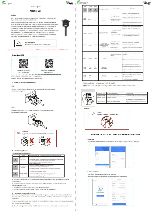
Guía rápidaMódulo WIFIAviso:Lea este manual detenidamente antes de usar el producto y guárdelo en unlugar donde pueda encontrarlo fácilmente.Debido a la actualización del producto y otros factores,el contenido de estemanual puede cambiar de vez en cuando.Tome el producto real como estándary obtenga el manual más reciente en www.grupotemper.es.A menos que seacuerde lo contrario, este manual solo se utilizarácomo guía.Cualquierdeclaración,información o sugerencia en este manual no tomaráningún tipo deresponsabilidad. Sin permiso por escrito,queda prohibido que cualquierempresa o individuo pueda extraer,copiar o transmitir de ninguna forma elcontenido de este documento(en parte o ensu totalidad).Advertencia:Retire el módulo WIFI después de apagarlo.Nota:Este módulo WIFI viene como accesorio con nuestra gama de inversores monofásicos y trifásicos con tecnología ONGRID.SOLARMAN inteligentepara usuario finalNegocios SOLARMANpara negocios4.Métodos de uso y avisos para el botón de reinicio4.1Métodos de uso y descripciones de pulsaciones de teclas para el botón de reinicioiPhone:busque"SOLARMAN Smart"en Apple Store.Android:busque"SOLARMAN Smart"en Google Play.1.Instalación del registrador revestidoTipo1Conecte el inversor como semuestra en elTipo2Conecte el registrador en la interfaz de comunicación del inversor comose muestra en el diagramaMANUAL DE USUARIO para SOLARMAN Smart APP1.RegistroAccede a SOLARMAN Smart y regístrate.Haga clic en"Registrarse"y cree su cuenta aquí.2.Estado del registrador2.Crear una plantaHaga clic en"Agregar ahora"para crear su planta.Complete la información básica de la planta y otra información aquí.El estado de funcionamiento normal del registrador,cuando el enrutador está conectado ala rednormalmente:1.Estado de conexión correcta y con servicio:la luz NET se mantiene encendida después deencender el registrador.2.El registrador funciona normalmente:la luz READY parpadea.3.Estado de conexión exisotda con el inversor:la luz COM sigue encendida.3.Procesamiento de estado anormalSi los datos en la plataforma son anormales cuando el registrador está funcionando, consulte la tablaque se muestra a continuación de acuerdo con el estado de las luces indicadoras para comprobar losproblemas.Si aún no se pueden resolver o el estado de las luces indicadoras no se muestra en la tabla ,comuníquesecon nuestro Servicio al Cliente.(Nota:utilice la siguiente consulta de tabla después del encendido durante al menos2 minutos).3. Agregar un registradorMétodo 1:Ingrese el SN del registrador manualmente.Método 2:Haga clic en el icono a la derecha y escanee para ingresar el SN del registrador.Puede encontrar el SN del registrador en la caja o en el propio aparato.Paso 3:Configuración automáticaEspere un momento para completar la configuración.Entonces el sistema cambiaráa la página siguiente.Haga clic en "Listo"para verificar los datos de la planta.(Por lo general,los datos se actualizaránen 10minutos)4.Configuración de redDespués de agregar el registrador,configure la red para garantizar un funcionamiento normal.Vaya a "Detalles de la planta"Lista de dispositivos", busque el SN de destino y haga clic en "Redes".Si se produce un error de configuración,compruebe los siguientes puntos e inténtelo de nuevo.(1)Asegúrese de que WLAN estéENCENDIDO.(2)Asegúrese de que WiFi sea normal.(3)Asegúrese de que el router inalámbrico no implemente la lista blanca-negra.(4)Elimine los caracteres especiales en la red Wi-Fi.(5)Acorte la distancia entre el teléfono y el dispositivo.(6) Intente conectarse a otro Wi-Fi.Advertencia:Asegúrese de que el registrador estéfuncionando correctamente antes de abandonar lainstalación. Si hay algo anormal,no abandone el lugar y comuníquese con el servicio al cliente.Paso 1:Confirmar información Wi-FiAsegúrese de que su teléfono se haya conectado a la red WiFi correcta. Haga clic en "Inicio".Aviso:No se admite Wi-Fi 5G.Si tiene alguna consulta técnica sobre nuestros productos,contáctenos y proporcione la siguiente información:1.Modelo del producto y número de serie del registrador.2.Modelo del producto y número de serie del inversor conectado.¡Gracias por su apoyo y cooperación!Queridos clientes,Muchas gracias por usar nuestros productos.Para brindarle un mejor servicio,complete la tarjeta de garantía y guárdela cuidadosamente.Paso 2:Conéctese a la red APHaga clic en "Ir a conectar"y busque la red "AP_XXXXX"correcta (XXXXXse refiere al SN del registrador).Si se requiere la contraseña,puede encontrar la contraseña en el cuerpo del registrador. Vuelva a SOLARMAN Smart APP,después de conectarse ala red AP.。

EM-1220 Hardware User’s ManualEdition 6.0, February 2017/product© 2017 Moxa Inc. All rights reserved.EM-1220 Hardware User’s ManualThe software described in this manual is furnished under a license agreement and may be used only in accordance withthe terms of that agreement.Copyright Notice© 2017 Moxa Inc. All rights reserved.TrademarksThe MOXA logo is a registered trademark of Moxa Inc.All other trademarks or registered marks in this manual belong to their respective manufacturers.DisclaimerInformation in this document is subject to change without notice and does not represent a commitment on the part of Moxa.Moxa provides this document as is, without warranty of any kind, either expressed or implied, including, but not limited to, its particular purpose. Moxa reserves the right to make improvements and/or changes to this manual, or to the products and/or the programs described in this manual, at any time.Information provided in this manual is intended to be accurate and reliable. However, Moxa assumes no responsibility for its use, or for any infringements on the rights of third parties that may result from its use.This product might include unintentional technical or typographical errors. Changes are periodically made to the information herein to correct such errors, and these changes are incorporated into new editions of the publication.Technical Support Contact Information/supportMoxa AmericasToll-free: 1-888-669-2872 Tel: +1-714-528-6777 Fax: +1-714-528-6778Moxa China (Shanghai office) Toll-free: 800-820-5036Tel: +86-21-5258-9955 Fax: +86-21-5258-5505Moxa EuropeTel: +49-89-3 70 03 99-0 Fax: +49-89-3 70 03 99-99Moxa Asia-PacificTel: +886-2-8919-1230 Fax: +886-2-8919-1231Moxa IndiaTel: +91-80-4172-9088 Fax: +91-80-4132-1045Table of Contents1.Introduction ...................................................................................................................................... 1-1Overview ........................................................................................................................................... 1-2 Package Checklist ............................................................................................................................... 1-2 Product Features ................................................................................................................................ 1-2 EM-1220 Hardware Specifications ......................................................................................................... 1-3 EM-1220 Hardware Block Diagram ........................................................................................................ 1-4 Appearance ........................................................................................................................................ 1-5 Dimensions ........................................................................................................................................ 1-6 2.EM-1220 Functionality ...................................................................................................................... 2-1EM-1220 Embedded Module Functions ................................................................................................... 2-2 RS-232/422/485 Serial Ports ............................................................................................................... 2-2 Console Port ...................................................................................................................................... 2-2 LAN Ports .......................................................................................................................................... 2-2 SD Signals ......................................................................................................................................... 2-2 GPIO ................................................................................................................................................. 2-2 Pin Assignments ................................................................................................................................. 2-2 Definition of SD Signals ....................................................................................................................... 2-4 Mechanical Specifications of the Pin Headers .......................................................................................... 2-4 3.EM-1220-DK Functionality ................................................................................................................. 3-1EM-1220-DK Development Board .......................................................................................................... 3-2 Combining the EM-1220-DK with the Embedded Module .......................................................................... 3-2 LED Indicators .................................................................................................................................... 3-2 Wiring Requirements ........................................................................................................................... 3-2 Connecting the Power ......................................................................................................................... 3-3 Grounding the EM-1220 Development Kit .............................................................................................. 3-3 Serial Ports and Pin Assignments .......................................................................................................... 3-4 Console Ports and Pin Assignments ....................................................................................................... 3-4 LAN Ports and Pin Assignments ............................................................................................................ 3-4 SD Socket .......................................................................................................................................... 3-5 Reset Button ...................................................................................................................................... 3-51Introduction Thank you for purchasing the Moxa EM-1220 Embedded Module. The product’s features include two software-selectable RS-232/422/485 serial ports, two 10/100 Mbps Ethernet ports, and SD signals for external SD socket connection based on the Moxa ARM9 32-bit 192 MHz communication processor. These features make the EM-1220 ideal for the core module of an industrial embedded system design.The EM-1220 Development Kit, which is designed for system and software program development at the system evaluation stage, is also available. The kit includes the EM-1220 and EM-1220-DK, which is the carrier board used to evaluate the EM-1220. The EM-1220’s pre-installed ready-to-run μClinux Kernel 2.6 makes it easy to develop programs for any application.In this manual, we introduce the hardware features and functions of the EM-1220 Embedded Module and the EM-1220 Development Kit. After a brief introduction to the hardware features, the manual focuses on installation and hardware configuration with device interfaces.tent here.The following topics are covered in this chapter:❒Overview❒Package Checklist❒Product Features❒EM-1220 Hardware Specifications❒EM-1220 Hardware Block Diagram❒Appearance❒DimensionsOverviewThe EM-1220 Embedded Module is designed for system integration and software development in industrial data applications. The module features 2 software-selectable RS-232/422/485 serial ports, two 10/100 MbpsEthernet ports, and an SD function based on the MOXA ART ARM9 32-bit 192 MHz communication processor.In addition, you may order the EM-1220 Development Kit. The kit includes an EM-1220 embedded module, an EM-1220-DK carrier board, and the items needed for setting up a basic layout. The kit is makes it easy for users to evaluate the functionality of the EM-1220. You can develop and integrate specific systems on the module in advance to make the EM-1220 Embedded Module completely compatible with industrial systems andapplications.The pre-installed open Linux operating system makes the EM-1220 suitable for developing the controlprograms used on a standard PC. The software you develop for your own applications can be stored in theonboard Flash memory. The EM-1220 lets you build an application that has a powerful serial communication capability, but which is still small in size. The EM-1220 is suited for control systems that use a distributed,embedded architecture, such as those systems used for manufacturing automation, intelligent transportation systems, medical management, and data acquisition and control.Package ChecklistThe EM-1220 package includes the EM-1220 embedded module only. The EM-1220 Development Kit isavailable for evaluation purposes. The EM-1220 Development Kit package contains the following items:• 1 EM-1220 Embedded Module• 1 EM-1220-DK, the carrier board of the EM-1220 Development Kit•Quick installation guide (printed)•Document & software CD•Cross-over Ethernet cable•Console port cableCBL-4PINDB9F-100: 4-pin header to DB9 (female) cable, 100 cm•Universal power adaptor•Warranty cardNOTE: Please notify your sales representative if any of the above items are missing or damaged.Product FeaturesThe EM-1220 Embedded Module has the following features:•MOXA ART ARM9 32-bit 192 MHz processor•On-board 16 MB RAM, 8 MB flash disk•software-selectable RS-232/422/485 serial ports•Dual 10/100 Mbps Ethernet for network redundancy•Ready-to-run μClinux Kernel 2.6 platform•SD signals supported for external SD socket connection•Built-in RTC, buzzer, Watchdog Timer•10 GPIOs reserved for system integration•Credit card size design for easy integration at any field site•Full-function development kit for quick evaluation and application development•-40 to 75oC wide temperature model availableEM-1220 Hardware SpecificationsComputerCPU: MOXA ART ARM9 32-bit 192 MHz processorOS (pre-installed):Embedded μClinux (kernel 2.6.19)DRAM: 16 MB onboardFlash: 8 MB onboardStorageStorage Expansion: SD signals for external Secure Digital (SD) socket connectionEthernet InterfaceLAN: 2 auto-sensing 10/100 Mbps ports (RJ45)Magnetic Isolation Protection: 1.5 KV built-inSerial InterfaceSerial Standards: RS-232/422/485, software-selectable, 2 portsESD Protection: 15 KV for all signalsConsole Port: TTL signal, 4-pin pin header outputSerial Communication ParametersData Bits: 5, 6, 7, 8Stop Bits: 1, 1.5, 2Parity: None, Even, Odd, Space, MarkFlow Control: RTS/CTS, XON/XOFF, ADDC® (automatic data direction control) for RS-485Baudrate: 50 bps to 921.6 Kbps (supports non-standard baudrates; see user's manual for details)Serial SignalsRS-232: TxD, RxD, DTR, DSR, RTS, CTS, DCD, GNDRS-422: TxD+, TxD-, RxD+, RxD-, GNDRS-485-4w: TxD+, TxD-, RxD+, RxD-, GNDRS-485-2w: Data+, Data-, GNDLEDsSystem: ReadyLAN: 10M/Link x 2, 100M/Link x 2Serial: TxD x 2, RxD x 2Physical CharacteristicsWeight:• EM-1220 Module: 40 g• EM-1220 Development Kit: 120 gDimensions:• EM-1220 Module: 80 x 50 mm (3.15 x 1.97 in)• EM-1220 Development Kit: 117 x 70 mm (4.61 x 2.76 in)Module Interface: Two 2 x 17 pin-headers (2.5 x 2.5 mm pitch)Environmental LimitsOperating Temperature:Standard Models: -10 to 60°C (14 to 140°F)Wide Temp. Models: -40 to 75°C (-40 to 167°F)Storage Temperature:Standard Models: -20 to 80°C (-4 to 176°F)Wide Temp. Models: -40 to 85°C (-40 to 185°F)Ambient Relative Humidity: 5 to 95% (non-condensing)Power RequirementsInput Voltage: 3.3 VDCPower Consumption:2.1W(************)Standards and CertificationsEMC: EN 55032 Class A, EN 61000-3-2 Class A, EN 61000-3-3, EN 55024, FCC Part 15 Subpart B Class AGreen Product: RoHS, CRoHS, WEEEReliabilityAlert Tools: Built-in buzzer and RTC (real-time clock)Automatic Reboot Trigger: Built-in WDT (watchdog timer)MTBF (mean time between failures): 405,735 hrsWarrantyWarranty Period: 5 yearsDetails: See /warrantyNote: The Hardware Specifications apply to the embedded computer unit itself, but not to accessories. Inparticular, the wide temperature specification does not apply to accessories such as the power adaptor and cables.EM-1220 Hardware Block DiagramAppearanceEM-1220 Development Kit (EM-1220 Embedded Module attached to the EM-1220-DK, the carrier board of EM-1220 Development Kit)EM-1220 Embedded ModuleTop View Bottom ViewEM-1220 Development KitDimensionsEM-1220 Embedded ModuleEM-1220-DK, Carrier board of EM-1220 Development Kit2EM-1220 FunctionalityIn this chapter, we explain the basic features of the EM-1220 Embedded Module.The following topics are covered in this chapter:❒EM-1220 Embedded Module Functions❒RS-232/422/485 Serial Ports❒Console Port❒LAN Ports❒SD Signals❒GPIO❒Pin Assignments❒Definition of SD Signals❒Mechanical Specifications of the Pin HeadersEM-1220 Embedded Module FunctionsThe EM-1220 Embedded Module is designed to be integrated directly into the user’s system and application.The module has two software-selectable RS-232/422/485 serial ports, dual 10/100 Mbps LAN ports, 1 RS-232 console port, and GPIO/SD signals. In addition, the EM-1220 uses the Moxa ART ARM9 32-bit 192 MHzcommunication processor, which ensures excellent performance for data transmission.The pre-installed μClinux Kernel 2.6.9 makes it easy for users to develop programs for a variety of applications.The EM-1220 is an ideal solution for manufacturing automation, intelligent transportation monitoring, andremote device control.RS-232/422/485 Serial PortsThe EM-1220 Embedded Module has 2 software-selectable RS-232/422/485 serial ports. Pin assignmentdiagrams are shown in a later section. The ports can be configured by software. Please refer to Software User’s Manual for details.Console PortThe EM-1220 Embedded Module has 1 console port for onsite configuration. The port supports TxD, RxD, GND, and TTL signals.LAN PortsThe EM-1220 Embedded Module has 2 10/100 Mbps LAN ports that can be used to set up a redundant Ethernet network for non-stop operation, and the on-board transformer provides 1.5 KV isolation protection. SD SignalsThe EM-1220 Embedded Module provides SD signals for storage expansion. Designers can use these signals to create an SD socket. Note that you can use a Secure Digital (SD) memory card compliant with the SD 1.0standard to provide up to 1 GB of additional memory space. However, the SD signals share the samemechanical layout with the GPIO. When you enable the SD signals, the GPIO function will be disabled, and vice versa.GPIOThe EM-1220 Embedded Module provides 10 software-selectable GPIOs. Note that users can choose to enable either the SD Signals or the GPIO function, but not both. When you enable the GPIO function, the SD Signals will be disabled.Pin AssignmentsThere are two 34-pin pin headers on the EM-1220 embedded module. To use the EM-1220 Embedded Module to develop your own independent system, refer to the following tables for the pin assignments of jumpers J1 and J2.Signals J1 Pin No. SignalsVCC(3.3V) 1 2 VCC(3.3V)VCC(3.3V) 3 4 VCC(3.3V)GND 5 6 GNDGND 7 8 GNDTxD0 (RS-232) 9 10 RxD0 (RS-232)RTS0 11 12 CTS0DTR0 13 14 DSR0RxD1 (RS-232) 15 16 DCD0CTS1 17 18 TxD1 (RS-232)DSR1 19 20 RTS1DCD1 21 22 DTR1Data-(A)0 / RxD-(A)0 23 24 Data-(A)1 / RxD-(A)1 Data+(B)0 / RxD+(B)0 25 26 Data+(B)1 / RxD-(A)1 Serial LED_Tx0 27 28 Serial LED_Rx0 Serial LED_Tx1 29 30 Serial LED_Rx1TxD-(A)0 31 32 TxD-(A)1TxD+(B)0 33 34 TxD+(B)1Signals J2 Pin No. SignalsConsole_RxD 1 2 Console_TxDEth1_TxD_out+ 3 4 GNDEth1_TxD_out- 5 6 Eth1_RxD_in+Eth1_LED_100M 7 8 Eth1_RxD_in-Eth0_TxD_out+ 9 10 Eth1_LED_10MEth0_TxD_out- 11 12 Eth0_RxD_in+Eth0_LED_100M 13 14 Eth0_RxD_in-GPIO0 15 16 Eth0_LED_10M GPIO2 17 18 GPIO1GPIO4 19 20 GPIO3GPIO6 21 22 GPIO5GPIO8 23 24 GPIO7Buzzer 25 26 GPIO9LED_Ready 27 28 SW ResetN/C 29 30 N/CGND 31 32 GNDGND 33 34 GNDDefinition of SD SignalsThe following table gives the definition of the SD signals. Note that the signal pins from the J2 pin header share the same pin as the GPIO.Signal Name Direction GPIO DescriptionSD_CLK Output GPIO 7 Clock signal to SD/MMCSD_CMD Bidirectional GPIO 2 Bidirectional line for command and responseSD_DAT<3:0> Bidirectional GPIO <6:3> Bidirectional line for read and write dataSD_CD Input GPIO 1 Card detectSD_WP Input GPIO 0 Write protectMechanical Specifications of the Pin Headers Refer to the following figures for the mechanical specifications of the Pin Headers on the EM-1220 Embedded Module. The figures define the mechanical specifications of jumpers J1 and J2 on the EM-1220.3EM-1220-DK FunctionalityThis chapter includes information about the EM-1220-DK (carrier board of the EM-1220 Development Kit). The following topics are covered in this chapter:❒EM-1220-DK Development Board❒Combining the EM-1220-DK with the Embedded Module❒LED Indicators❒Wiring Requirements❒Connecting the Power❒Grounding the EM-1220 Development Kit❒Serial Ports and Pin Assignments❒Console Ports and Pin Assignments❒LAN Ports and Pin Assignments❒SD Socket❒Reset ButtonEM-1220-DK Development BoardThe EM-1220 Development Kit is a well-designed PCB board with complete layout. The kit helps users evaluate, develop, and integrate the EM-1220 Embedded Module into their systems and applications. Simply combine the EM-1220 Embedded Module with the Development Kit to start porting the relevant software, and create asolution for the applications you wish to implement.Refer to the following picture for the basic layout of the EM-1220-DK.Combining the EM-1220-DK with the Embedded ModuleInsert the EM-1220 Embedded Module vertically onto the EM-1220-DK. Note that the Pin marked “J1” on the Embedded Module must be matched with the Pin marked “J1” on the EM-1220-DK; and the Pin marked “J2” on the Embedded Module must be matched with the Pin marked “J2” on the EM-1220-DK. Be careful wheninstalling the board to avoid damaging the pins.LED IndicatorsThe following table explains the function of the LED indicators located on the EM-1220-DK.LED Name LED Color LED FunctionReady Green Power is on and system functions normally.P1, P2 (Tx) Green Serial port 1, 2 is transmitting data.Off Serial port 1, 2 is not transmitting data.P1, P2 (Rx) Yellow Serial port 1, 2 is receiving data.Off Serial port 1, 2 is not receiving data.Wiring RequirementsThis section describes how to connect the EM-1220 Development Kit to serial devices.You should heed the following common safety precautions before proceeding with the installation of anyelectronic device:Use separate paths to route wiring for power and devices. If power wiring and device wiring paths must cross, make sure the wires are perpendicular at the intersection point.NOTE: Do not run signal or communication wiring and power wiring in the same wire conduit. To avoidinterference, wires with different signal characteristics should be routed separately.Use the type of signal transmitted through a wire to determine which wires should be kept separate. The rule of thumb is that wiring that shares similar electrical characteristics can be bundled together.Keep input wiring and output wiring separate.It is advisable to label the wiring to all devices in the system.Be sure to disconnect the power cord before installing and/or wiring your EM-1220 Development Kit.Connecting the PowerYou may use the 3-pin terminal block for connecting the power. The power input range of the EM-1220-DK is from 12 to 48 VDC. If the power is properly supplied, the “Ready” LED will glow a solid green after a 25 to 30 second delay.Grounding the EM-1220 Development Kit Grounding and wire routing help limit the effects of noise due to electromagnetic interference (EMI). Run the ground wire from the ground screw to the grounding surface prior to connecting devices.Serial Ports and Pin AssignmentsThe EM-1220 Development Kit has 2 software-selectable serial ports. If you would like to connect to a serial device, use male DB9 connectors. The ports can be configured for RS-232, RS-422, or RS-485 by software.Refer to the Software User’s Manual for details. Pay attention to the cable length for the various serialcommunication standards. Refer to the following figure for the pin assignments of the DB9 connector.Male DB9 Port Pin RS-232 RS-422 4-wire RS-485 2-wire RS-4851 DCD TxDA(-) TxDA(-) –2 RxD TxDB(+) TxDB(+) –3 TxD RxDB(+) RxDB(+) DataB(+)4 DTR RxDA(-) RxDA(-) DataA(-)5 GND GND GND GND6 DSR – – –7 RTS – – –8 CTS – ––Console Ports and Pin AssignmentsThe serial console port on the EM-1220-DK is a 4-pin pin-header RS-232 port, which support TxD, RxD, and GND signals. It is designed for serial console terminals, which can be used for local configuration andidentifying the EM-1220-LX boot up message. The pinouts of this RS-232 console port are shown in the figure below.Serial Console Port & Pinouts Serial Console CablePin Signal1 TxD2 RxD3 NC4 GNDLAN Ports and Pin AssignmentsThe EM-1220 Development Kit has two 10/100 Mbps LAN ports. Connect one end of the Ethernet cable to the Development Kit LAN port and the other end of the cable to the Ethernet network. The LAN ports use 8-pin RJ45 connectors. See the following diagram for the pinouts.8-pin RJ45Pin Signal1 ETx+2 ETx-3 ERx+4 –5 –6 ERx-7 –8 –SD SocketThe EM-1220 Development Kit provides an internal SD socket for storage expansion. The socket allows users to use a Secure Digital (SD) memory card compliant with the SD 1.0 standard for adding up to 1 GB ofadditional memory space. Plug the SD card directly into the socket. Remember to press the SD card first if you want to remove it. Note that the SD will not work if you enable the GPIO function. Refer to the section about the EM-1220’s SD function to see a table that describes the SD card interface.Reset ButtonPress the Reset button on the EM-1220-DK continuously for at least 5 seconds to load the factory defaultconfiguration. After the factory default configuration has been loaded, the system will reboot automatically. We recommend that you only use this function if the software is not working properly and you want to load factory default settings. To reset an embedded Linux system, always use the software reboot command />reboot to protect the integrity of data being transmitted or processed. The Reset button is not designed to hard reboot the EM-1220 Development Kit.。
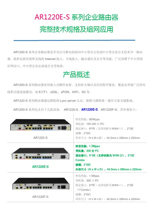
AR1220E-S系列企业路由器完整技术规格及组网应用AR1200-S系列企业路由器是华为公司推出的面向中小型办公室或中小型企业分支的多合一路由器,提供包括有线和无线的Internet接入、专线接入、融合通信及安全等功能,广泛部署于中小型园区网出口、中小型企业总部或分支等场景。
产品概述AR1200-S系列路由器采用嵌入式硬件加密,支持防火墙以及应用程序服务,覆盖业界最广泛的有线和无线连接模式,如E1/T1、xDSL、xPON、WiFi、3G等。
AR1220-S系列路由器通过微软的Lync server认证,能够与微软统一通信方案无缝集成。
AR1200-S系列包含以下几款设备:AR1220-S、AR1220E-S、AR1220F-S,其外观如下:AR1220-S •••••AR1220E-S •••••AR1220F-S •••••AR1200-S支持多种接口卡,包括以太网接口卡、E1/T1/PRI/VE1接口卡、同异步接口卡、ADSL2+/G.SHDSL接口卡、ISDN接口卡、EPON/GPON接口卡等。
按使用槽位的不同,可分为SIC 卡(灵活接口卡)和WSIC卡(双宽SIC卡)。
产品特性与价值3AR1200-S系列企业路由器采用多核CPU和无阻塞交换架构,产品性能业界领先,充分满足企业及分支机构网络未来多元化扩展、不断增长的业务需求。
•使用多核CPU,提高数据、语音的并发处理能力,为大容量业务的全方位部署创造条件•无阻塞交换,业务转发无瓶颈•协议管理、业务处理、数据交换独立分布处理,性能更高,业务更可靠•路由交换一体化,跨板卡交换效率高,配置维护灵活简单•板卡热插拔,风扇等关键硬件冗余设计,保证业务安全稳定移动模式固定模式通过OSP与第三方IT系统集成和对接,为企业客户实现统一通信的业务体验,使客户、代理商、第三方和厂家都可以是开发者和使用者,真正实现业务价值链的共赢。
•快速集成与定制业务,满足用户个性化需求•深度融合各类业务,无需部署专门服务器,节省投资,易于管理•与云侧业务实时刷新和同步,本地业务由本地处理,提高质量和效率安全业务接入AR1200-S在业务顺利开展的同时有效地保障企业网的安全,从用户接入控制、报文检测、到主动防御形成一套完整的安全防护机制,实现用户投资回报最大化。
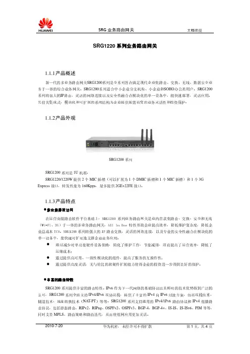
SRG1220系列业务路由网关1.1.1产品概述新一代的多业务路由网关SRG1200系列是全系列旨在满足现代企业集路由、交换、无线、数据安全业务于一体的综合业务网关。
SRG1200系列适合中小企业分支机构、小企业和SOHO办公类用户。
SRG1200系列将强大的IP路由,灵活的网络连接以及安全性融合在模块化的单一设备中,能快速部署,灵活应用。
凭借其集成式、模块化和可扩展的系统结构为企业提供随需而变的业务灵活性和投资保护。
1.1.2产品外观SRG1200系列SRG1200系列是1U机框。
SRG1220/1220W提供2个MIC插槽(可以扩展为1个DMIC插槽和1个MIC插槽)和1个3G Express接口,转发性能为160Kpps,最多提供2GE+22FE接口。
1.1.3产品特点多业务并发访问多业务并发访问在运营商级路由软件平台基础上,SRG1200系列业务路由网关是业内首款集路由、交换、安全和无线(Wi-Fi、3G)于一体的多业务路由网关,All in One特性帮助企业提高效率,降低维护复杂度,降低企业总成本TCO。
SRG1200系列将强大的IP路由交换,灵活的网络连接,以及专业的安全性融合在模块化的单一设备中,能快速可扩展地支撑企业业务应用。
通过减少对单功能硬件设备依赖,简化了维护工作,节能减排,进而提高了运营效率,降低了运维成本;通过提供高可用、一致性模块化的组件,提高了服务的互操作性;通过提供高度灵活,无与伦比的软硬件扩展能力使得企业的投资进一步得到良好的保护。
丰富的路由特性丰富的路由特性SRG1200系列提供丰富的路由特性。
IPv6作为下一代网络的基础协议以其鲜明的技术优势得到广泛的认可,SRG1200系列全面支持IPv4/IPv6双协议栈,提供了丰富的IPv4向IPv6过渡方案,包括双栈技术、隧道技术、地址转换技术(NAT-PT)等等。
SRG1200系列支持通用的IPv4/1Pv6路由协议和IPv4组播路由协议,包括静态路由、RIPv2、RIPng、OSPFv2、OSPFv3、BGP-4、BGP-4+、IS-IS、IS-ISv6、PIM等等,同时支持MPLS、路由策略和路由迭代,从而使组网应用更加灵活。

精密型伺服计算机系统插拔力试验机型号: O’K-1220S电源: 1∮220V 50Hz前言感谢贵司选择了本公司的产品,本公司不仅给贵司提供质量优良的产品,而且将提供可靠的售后服务。
为确保使用人员之人身安全及仪器的完好性,在使用本仪器前请充分阅览此操作手册,确实留意其使用上的注意事项。
本操作手册详细介绍此仪器之设计原理、依据标准、构造、操作规范、校正、保养、可能故障的情形及排除方法、电气图等内容。
在本操作手册中如有提及之各种“试验规定”、“标准”时均只作参考用,如贵司觉得有异议请自行检阅相关标准或数据。
特别声明:●本操作手册不能作为向本公司提出任何要求的依据。
●本操作手册的解释权在本公司。
安全上的注意1.安全上的记号:在本手册中,关于安全上的注意事项以及使用仪器时有下列重要的各显示事项,为了防止意外事故及危险,请务必遵守下列危险﹑警告﹑注意的记言:2.在本仪器上,以下记号表示注意﹑警告。
壹﹑概论一﹑用途::●本机适用于各种连接器的插拔及各种压缩、拉伸破环性试验。
二﹑原理:●本机经伺服控制系统施以一定之荷重及速度,再通过力量传感器感应力量并以信号形式传输给计算机系统,从而判定机台之各种性能。
贰﹑仪器说明一﹑仪器结构说明 (图1):二﹑控制面板(图2):注:面板上上升下降按钮均为点动按钮三、软件说明21 3 4 567 1. 力量傳感器 2. 上夾具3. 安全上限設定4. 測試平臺5. 橫檔6. 二微調整座7. 控制面板8. 电脑8 1. 電源指示燈2.上升下降极限指示灯 3. 电源开关4. 机台测试停止按钮5. 测试开始按钮6. 高速上升按钮7. 高速下降按钮8. 中速上升按钮9. 中速下降按钮 10. 低速上升按钮 11. 低速下降按钮6 51 圖2 圖1234 10 11 9 86 7见软件说明书三﹑仪器规格(表1):参﹑仪器安装一、电源条件:请依本机铭牌上标示配置正确电源,三相电源请注意相位顺序。

目录1产品介绍 (1)1.1简介 (1)1.2产品配件 (2)1.3状态图标 (2)1.4LandStar7测地通软件 (2)2使用入门 (4)2.1开关机 (4)2.2安装SIM卡与SD卡 (4)2.3按键功能说明 (5)2.4手薄充电 (6)2.5重要提示 (6)3基本功能介绍 (7)3.1数据存储与传输 (7)3.2语言与输入法设置 (8)3.3网络切换 (9)3.4恢复出厂设置 (10)3.5NFC功能 (11)3.6手持机功能 (12)4手簿内核升级 (14)5手簿规格说明 (17)6获取技术支持 (19)1产品介绍1.1简介按键【主屏幕键】:解锁后,在任何界面,点击返回主屏幕。
【返回键】:点击返回之前屏幕。
【菜单键】:点击显示当前打开的应用程序界面,点击选中的界面可直接进入当前所显示的界面。
1.2产品配件1HCE320手簿2HCE320手簿点触笔3HCE320手簿贴膜4HCE320手簿背带5HCE320手簿数据线6HCE320手簿适配器1.3状态图标图标说明图标说明充电状态振动模式Wifi状态手簿信号强度闹钟飞行模式Bluetooth状态应用上传Wifi同步下载上传应用下载USB连接成功1.4LandStar7测地通软件简介:Landstar7是华测公司的最新研发的一款安卓版测量软件,它充分利用安卓平台稳定、开放的优势,以简单、易于使用为目标,创新性加入5种常用工作模式,一键即可完成RTK设置;同时配备强大的图形编辑引擎,并首次在常规测量软件中添加了对图层、代码等属性的编辑和绘制,在野外即可自动成图;充分优化的数据库结构,支持8万点以上的海量数据管理和百兆超大底图;还结合强大的云服务功能,让数据的分享、备份更简单。
软件界面如下:注意:点击软件界面右上角的问号进入帮助界面,若没有安装过帮助文档,则会提示请安装帮助文档。
此时,只要把LandstarHelp_zh拷进手簿,找到它点击进行安装即可。
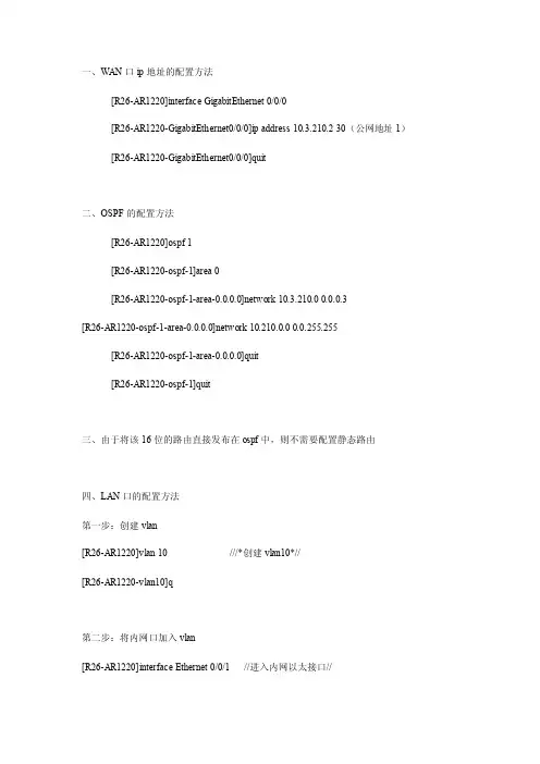
一、WAN口ip地址的配置方法[R26-AR1220]interface GigabitEthernet 0/0/0[R26-AR1220-GigabitEthernet0/0/0]ip address 10.3.210.2 30(公网地址1)[R26-AR1220-GigabitEthernet0/0/0]quit二、OSPF的配置方法[R26-AR1220]ospf 1[R26-AR1220-ospf-1]area 0[R26-AR1220-ospf-1-area-0.0.0.0]network 10.3.210.0 0.0.0.3[R26-AR1220-ospf-1-area-0.0.0.0]network 10.210.0.0 0.0.255.255[R26-AR1220-ospf-1-area-0.0.0.0]quit[R26-AR1220-ospf-1]quit三、由于将该16位的路由直接发布在ospf中,则不需要配置静态路由四、LAN口的配置方法第一步:创建vlan[R26-AR1220]vlan 10 ///*创建vlan10*//[R26-AR1220-vlan10]q第二步:将内网口加入vlan[R26-AR1220]interface Ethernet 0/0/1 //进入内网以太接口//[R26-AR1220-Ethernet0/0/4]port link-type access //配置为access模式// [R26-AR1220-Ethernet0/0/4] port default vlan 10 //将接口加入vlan10// [R26-AR1220-Ethernet0/0/4]q(如果其他接口也想直连pc,则须进入相应的接口采用相同的配置即可)第三步:配置vlanif网关地址[R26-AR1220]interface Vlanif 10[R26-AR1220-Vlanif10]ip address 192.168.1.1 255.255.255.0[R26-AR1220-Vlanif10]quit--------------------------------------------------------------------------------陈乾坤Chenqiankun华为企业业务安捷信交付与服务业务部Agisson, Delivery & Service Dept, Huawei Enterprise Business GroupMobile:186****1186Contact: 400-830-2118呼叫座席号:938E-mail:**********************北京市海淀区中关村北清路156号实创科技示范园华为公司L05Huawei building,No.156,Beiqing Road,Haidian District,Beijing 100095, P.R.China。
华为AR1220-S<Huawei>dis cur[V200R002C01SPC200]#snmp-agent local-engineid 800007DB037054F595C80Dsnmp-agent#http server enable#drop illegal-mac alarm#dns resolvedns server 218.30.19.40dns server 61.134.1.4dns proxy enable#dhcp enable#set transceiver-monitoring disable#acl name gigabitethernet0/0/1 2998rule 5 permitacl name gigabitethernet0/0/0 2999rule 5 permit#ip pool vlanif1gateway-list 192.168.0.1network 192.168.0.0 mask 255.255.255.0dns-list 192.168.0.1#aaaauthentication-scheme defaultauthorization-scheme defaultaccounting-scheme defaultdomain defaultdomain default_adminlocal-user admin password cipher %$%$(b(0PYf#e7g|)+,h049$N6-$%$%$ local-user admin privilege level 3local-user admin service-type web http#firewall zone webtrustpriority 10#firewall zone webuntrustpriority 5#firewall interzone webtrust webuntrust#interface Dialer1link-protocol pppppp chap user 029********ppp chap password cipher %$%$w}*]!`E5z9;COL6!h"P~,:1(%$%$ppp pap local-user 029******** password cipher %$%$@m9%Zl/.u=1O!$*9`0}Q,-$x%$%$ppp ipcp dns admit-anyppp ipcp dns requesttcp adjust-mss 1400ip address ppp-negotiatedialer user 029********dialer bundle 1dialer-group 4nat outbound 2998#interface Vlanif1ip address 192.168.0.1 255.255.255.0dhcp select globalzone webtrust#interface Ethernet0/0/0#interface Ethernet0/0/1#interface Ethernet0/0/2#interface Ethernet0/0/3#interface Ethernet0/0/4#interface Ethernet0/0/5#interface Ethernet0/0/6#interface Ethernet0/0/7#interface GigabitEthernet0/0/0description 1_Management_Internet_R_gigabitethernet0/0/0ip address 61.185.8.128 255.255.255.128nat outbound 2999#interface GigabitEthernet0/0/1pppoe-client dial-bundle-number 1description 1_Internet_R_gigabitethernet0/0/1#interface NULL0#dialer-ruledialer-rule 4 ip permit#ip route-static 0.0.0.0 0.0.0.0 Dialer1ip route-static 0.0.0.0 0.0.0.0 GigabitEthernet0/0/0 61.185.8.129#user-interface con 0authentication-mode passwordset authentication password cipher %$%$8`10'-)aU@"#G7Sq&x9O,|sjI[6IMjUD&5J]/~)J OKSH.%yt%$%$user-interface vty 0 4user-interface vty 16 20#voice#diagnose#return<Huawei>saveThe current configuration will be written to the device.Are you sure to continue? (y/n)[n]:yIt will take several minutes to save configuration file, please wait............Configuration file had been saved successfullyNote: The configuration file will take effect after being activated。
PDU Básico Monofásico de 2.4kW 120V, 13 Tomacorrientes NEMA 5-15/20R, Entrada NEMA L5-20P, Cable de 4.57 m [15 pies], Instalación en 1U de RackNÚMERO DE MODELO:PDU1220TEntrega energía monofásica de 120V CA a múltiples cargas desde un tomacorriente de la instalación, generador o sistema UPS en un ambiente de TI de alta densidad. Ideal para aplicaciones de redes, telecomunicaciones, seguridad, audio / video y de refuerzo de sonidoGeneralEl PDU Básico Monofásico de 2.4kW 120V PDU1220T es la unidad de bajo costo perfecta para redes, telecomunicaciones, aplicaciones de refuerzo de sonido, audio/video y seguridad. Adaptado perfectamente para ambientes de TI de alta densidad, el PDU1220T cuenta con un solo banco de caga con breaker con 13 tomacorrientes NEMA 5-15/20R—12 en la parte posterior y uno al frente. La clavija de entrada NEMA L5-20P con cable de 4.57 m [15 pies] de longitud se conecta a la fuente de alimentación de CA de su instalación, generador o UPS protegido para distribuir energía al equipo conectado.El diseño sin switch evita un apagado accidental, que podría originar un tiempo muerto costoso. Un breaker de 20A protege al equipo conectado contra sobrecargas peligrosas. El gabinete completamente metálico se instala en 1U de espacio en racks de 19" de estándar EIA, así como en una pared, o banco de trabajo o debajo de un mostrador. Con un rack compatible y el accesorio PDUSIDEBRKT de Tripp Lite (vendido por separado), puede adaptar el PDU1220T para instalación vertical en 0U de rack.CaracterísticasDistribución Confiable de Energía MonofásicaPDU de bajo costo ideal para aplicaciones de refuerzo de redes, telecomunicaciones, seguridad, audio/video y sonidoq13 tomacorrientes NEMA 5-15/20R en un banco de carga con breakerqEl breaker de 20A protege los tomacorrientes contra sobrecargasqClavija de entrada NEMA L5-20P con cable de 4.57 m [15 pies]qPoste de tierra del panel posteriorqDiseño sin SwitchEvita apagados accidentales y costoso tiempo muertoq DestacadoEntrada NEMA L5-20P concable de 4.57 m [15 pies]q13 tomacorrientes NEMA 5-15/20R—12 en la parte trasera y 1 en el frenteqEl diseño sin switch evita elapagado accidentalqGabinete reversible totalmente metálicoqSe instala en un rack o pared o bajo un mostradorqEl Paquete IncluyePDU1220T; PDU BásicoMonofásico de 2.4kW 120VqAccesorios de instalaciónqManual del PropietarioqEspecificacionesVersátiles Opciones de InstalaciónSe instala horizontalmente en 1U de racks de 2 y 4 postes de 19" compatible con la norma EIAq El gabinete reversible completamente metálico ve hacia el frente o hacia atrás en el rackq Listo para instalación vertical en 0U sin herramientas con el PDUSIDEBRKT opcional (vendido por separado)qAdemás se instala en pared, banco de trabajo o bajo un mostradorq© 2023 Eaton. All Rights Reserved. Eaton is a registered trademark. All other trademarks are the property of their respective owners.。
目录一、升级路由器固件版本 (2)二、对路由器进行接口相关的配置 (2)三、DHCP配置 (4)四、上网行为管理 (5)五、网络安全 (9)六、QOS流量控制 (10)一、升级路由器固件版本1.首先去飞鱼星官网检查是否有新的IOS。
去官网查看后,发现有新的IOS,但是有硬件版本要求,硬件版本查看在路由器的下面,条形码附近有V4B4字样,其中V4B就是路由器的硬件版本。
2.下载相应的IOS,在升级IOS前,请将路由器恢复出厂设置3.等待路由器重启完毕后,点击固件升级功能。
选择下载好的IOS文件,耐心等待升级完成。
4.在路由器升级完成后,请再次将路由器恢复出厂设置。
以避免再以后使用中出现其他莫名其妙的问题。
升级完毕后,路由器版本如下:二、对路由器进行接口相关的配置1.wan口设置根据校区使用的带宽线路,选择使用PPOE还是静态IP。
其中,路由器上的wan1、wan2为固定wan口,不可作为lan口使用。
Lan2/wan4、lan3/wan3为动态接口,根据IOS 内部设定自动判定这两个接口为lan口还是为wan口。
n口设置根据校区的IP段,输入对应的内网地址,总部规定,路由器地址为**.**.**.254。
更改lan口地址后,再重启路由器后,DHCP也会相应自动改变。
关于接口相关配置,在这里不做过多阐述。
在配置好lan口与wan口后,必须重启路由器,才能使配置生效。
三、DHCP配置IP与MAC地址绑定功能,可以起到一些防止ARP攻击的效果,电脑较少的校区(20-30),推荐启用。
电脑较多的校区(60-80),如果地址池不够大,则不推荐启用。
因为每绑定一个MAC地址,将永久性占用一个IP地址,假如地址池不够大,移动设备又多,而且不手动释放DHCP,那么很有可能在很久以后,出现客户机无法获取IP的问题,解决方法为释放DHCP地址。
静态地址分配功能对于IP的规划起到非常好的作用。
这样的好处在于,可以进行人性化的上网行为管理。
华为AR1220-S设置教程首次登录系统简介当用户需要为第一次上电的设备进行配置时,可以通过Console口、MiniUSB口登录设备。
一块主控板提供一个Console口(端口类型为EIA/TIA-232 DCE)、一个MiniUSB口。
通过将用户终端的串行端口与设备Console口直接连接,或者将用户终端的USB口与设备MiniUSB口直接连接,实现对设备的本地配置。
说明:在通过MiniUSB口登录设备前,需要在用户终端安装MiniUSB接口的驱动程序。
同一时刻,MiniUSB端口和Console口只有一个可以使用。
通过MiniUSB口登录路由器安装路由器驱动程序在PC端安装路由器驱动程序AR_MiniUSB_driver,使PC端可以发现并识别AR1200-S。
背景信息此驱动程序仅支持Windows XP/VISTA/7操作系统。
操作步骤在PC端双击驱动程序的安装文件并点击“Next”,如图1所示。
图1 PC端运行驱动程序选择“I accept the terms in the license agreement”并点击“Next”,如图2。
图2 接受软件协议条款点击“Change”可以更改驱动解压的路径,然后点击“Next”,如图3所示。
图3 选择驱动解压路径点击“Install”后进行解压,完成后点击“Finish”结束解压,如图4所示。
图4 完成驱动的解压•在刚才指定的解压路径下找到“DISK1”文件夹,进入找到“setup.exe”图标并双击。
•点击“下一步”,选择“我接受许可证协议中的条款”项并点击“下一步”进入驱动安装。
•点击“完成”结束驱动程序的安装。
鼠标右键点击“我的电脑”,单击“管理”–>“设备管理器”–>“端口(COM和LPT)”,可以看到一个“TUSB3410 Device (COM3)”的设备即为路由器。
说明:如果在设备管理器中没有找过“TUSB3410 Device (COM3)”的设备,请重新安装驱动或者更换MiniUSB 线缆重新连接。