电气工程专业英语第2章
- 格式:ppt
- 大小:300.00 KB
- 文档页数:36
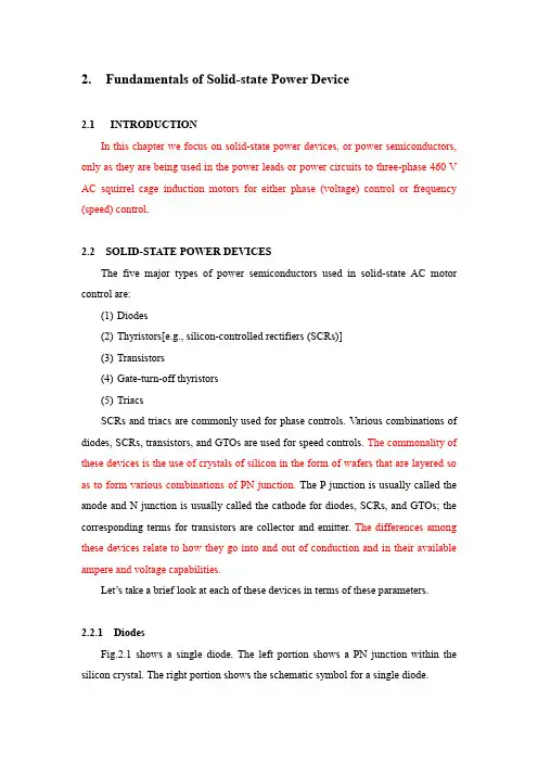
2.Fundamentals of Solid-state Power Device2.1INTRODUCTIONIn this chapter we focus on solid-state power devices, or power semiconductors, only as they are being used in the power leads or power circuits to three-phase 460 V AC squirrel cage induction motors for either phase (voltage) control or frequency (speed) control.2.2 SOLID-STATE POWER DEVICESThe five major types of power semiconductors used in solid-state AC motor control are:(1)Diodes(2)Thyristors[e.g., silicon-controlled rectifiers (SCRs)](3)Transistors(4)Gate-turn-off thyristors(5)TriacsSCRs and triacs are commonly used for phase controls. Various combinations of diodes, SCRs, transistors, and GTOs are used for speed controls. The commonality of these devices is the use of crystals of silicon in the form of wafers that are layered so as to form various combinations of PN junction. The P junction is usually called the anode and N junction is usually called the cathode for diodes, SCRs, and GTOs; the corresponding terms for transistors are collector and emitter. The differences among these devices relate to how they go into and out of conduction and in their available ampere and voltage capabilities.Let’s take a brief look at each of these devices in terms of these parameters.2.2.1 DiodesFig.2.1 shows a single diode. The left portion shows a PN junction within the silicon crystal. The right portion shows the schematic symbol for a single diode.When the anode (P) is positive with respect to the cathode (N), forward current will flow, with a relatively low voltage drop in the diode itself. When the polarity is reversed, only a slight reverse leakage current will flow. This is illustrated in Fig.2.2. The forward voltage drop is usually about 1 V, independent of the currentrating.The forward current rating of a diode depends on its size and design, both of which are predicted on the need to dissipate the heat generated within the device so that the maximum junction temperature (usually 200。
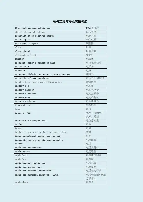
电气工程师专业英语词汇10kV distribution substation 10kV配电所abrupt change of voltage 电压突变accumulation of electric energy 电能存储actuating coil 动作线圈adjustment diagram 调整图alarm 报警alarm signal 报警信号alternating light 变光灯ammeter 电流表apparent energy consumption unit 单位视在能耗arc furnace 电弧炉armature 电枢arrester; lighting arrester; surge diverters 避雷器automatic voltage regulator 电压自动调整器backlighting; background illumination 背景照明battery box 电池箱battery charger 电池充电器battery contactor 电池接触器battery fuse 电池保险丝battery resistor 电池电阻器blow-out coil 磁吹线圈boom 吊杆bracket (OCS) 底座(接触网);支架;托架bracket for headspan wire 定位索底座bridge 电桥brush 电刷built-in wardrobe; built-in closet; closet 壁灯bulb; light(lamp) bulb; electric bulb 灯泡butterfly valve with electric actuator 电动蝶阀button 电钮cable and accessories 电缆及附件cable armour 电缆铠装cable bays 电缆电线间隔cable box 电缆箱cable bracket; cable tray 电缆托架cable continuity test 电路复测cable differential protection 电缆差动保护cable distribution cabinets (CDCs)电缆分线箱(电缆分歧箱)cable drum 电缆盘cable duct cable conduit 电缆管道cable duct; cable trench 电缆沟cable end; cable lug 电缆端头cable fault locator 电缆故障探测仪cable gallery 电缆廊道cable hanger; cable suspender 电缆吊架cable laying laying of cables 电缆敷设cable marking 电缆标志cable rack 电缆架cable shaft 电缆竖井cable sleeve; electrical wire conduit 电缆套管cable support 电缆支架cable tapping box 电缆分接箱cable terminal 电缆终端cable terminal box 电缆盒cable tray 电缆托架cable trenches with chequer plates 带方形盖板的电缆沟槽cable trough 电缆沟槽cable trough; trough 电缆槽cable tunnel; cable-subway 电缆隧道cable vault 电缆室cable work 电缆厂capacitance 电容capacitance compensation 电容补偿capacitive charges 电容电荷capacitive voltage transformer 电容式电压互感器capacitor 电容器capacitor bank 电容器组capacitor compensator 电容补偿器capacitor coupling 电容耦合capacitor filtering 电容滤波catenary/messenger 承力索catenary; messenger wire; catenary wire 承力索ceiling lamp ceiling light 顶灯ceramic wall bushings 穿墙套管changeover box 电源切换箱changeover box for smoke curtain 挡烟垂幕电源切换箱circuit 电路circuit connection 电路接线circuit diagram 电路图circuit diagrams 电路图circuit diagrams 电路图circuit parameter 电路参数circuit-breaker unit 断路器单元closed circuit 闭路closed circuit TV (CCTV) 闭路电视code for electrical design and installation 电气设计安装规范coefficient of resistivity 电阻系数compensation 补偿compensation reactor 补偿电抗器concealed piping; concealed pipe 暗管concealed wiring; concealed electric wiring 暗线condenser 电容器condenser bank(block) 电容器组condenser charge 电容器充电condenser discharge 电容器放电condenser reactance 电容器电抗conductor 导线conductor rail 导电轨conductor resistance 导体电阻contact 触头continuous carrying capacity 持续载流能力corona 电晕cross-span drop bracket 定位索定位支座current & voltage transducer 电流电压变换器current amplification 电流放大current relay 电流继电器current relay 电流继电器current transformer (CT) 电流互感器de-energize 断电diesel generator; diesel dynamo 柴油发电机diesel power plant; diesel generating station 柴油发电站differential protection 差动保护differential protection cables 差动保护电缆differential relay 差动继电器digital format 电子文档direct feeding system with return cable 带回流线的直接供电方式(TRNF供电方式)directional coil 定向线圈directional coupler 定向耦合器directional lighting 定向照明dispatching centre; load dispatching centre; control调度中心centredisplay lighting 陈列品照明district transformer station and distribution center 地区变、配电所drawer 抽屉柜drawout design 抽出式设计drop bracket 吊架drop bracket 定位单环, 定位支座electric coupler 电器连接electric displacement 电位移electric equipment inspection railcar 电气检测车electric hoist (block) 电动葫芦electric horn 电喇叭electric installation drawing 电气图纸electric joint 电气分断点electric potential 电势electric power fitting 电力金具electric railway 电气铁道electric resistance; resistivity 电阻率electric siren 电笛electric system 电气系统electric traction 电力牵引electric traction feeding system 电力牵引供电系统electric traction telemechanical system 电力牵引远动系统electrical apparatus for explosive atmospheres 爆炸环境用电气设备electrical design 电气设计electrical diagrams 电气图electrical energy 电能electrical equipment (appliance) 电器electrical experimental equipment 电工实验设备electrical installation; electrical fitting 电气安装electrical lamp; electric light 电灯electrical maintenance case 电器维修箱electrical outlet 电气出线口electrical rating 电气额定值electrician 电工electrification 电气化electrification interference 电气化干扰electrification interference 电气化干扰electrified railway 电气化铁路electrified railway remodeling 电气化铁道改造,电气化铁路改造electrified track 电气化铁道electromaginetic induction 电磁感应electromagnetic relay 电磁继电器electronic AC stabilizer 电子交流稳压器electronic information processing 电子信息处理electroplated coating of zinc 电镀锌emergency battery 备用电池energy transmission 电能传输factory site; location of factory 场致发光灯fall of current 电流下降fall of voltage 电压下降fastening blacket 抱箍fiber glass steel 玻璃钢floor special purpose receptacle 地面专用插座fluorescent lamp ballast with emergency function 带应急功能的荧光灯镇流器fly light gallery 灯光天桥frequency-modulated, digital telegram 调频数字电报galvanized iron wire strands 镀锌钢绞线galvanized steel sheet 镀锌钢管galvanometer; rheometer; current meter 电流计glass reinforced plastic 玻璃纤维加劲塑料ice 冰雪impulse current 冲击电流incandescent lamp base 白炽灯灯头incandescent lamp; incandescent filament lamp 白炽灯incandescent lighting 白炽灯照明inductance 电感inductance-capacitance meter 电感器industrial frequency AC electric traction system 单相工频交流电力牵引制inner covering 电缆内护层inner covering; bedding sheath 电缆内套insulation window 保温窗intensity of current 电流强度interrupter; circuit breaker; breaker 断路器,续断器interruption of current 断路isolux curve 等照度曲线kilowatt-hour meter; watt-hour meter; electric meter 电能表lamination 叠片lamp bridge 灯桥lamp socket; lamp holder; lamp base 灯座lamp; light; lantern 灯lamplight; lighting 灯光lamps; lighting fixtures 灯具lampshade lamp cover 灯罩leading 超前lead-out 出线life terminal 带电端子light control 灯光控制light trough; light slot; troffer 灯槽lighthouse beacon; pharos 灯塔lighting standard; lighting post; lighting pole 灯柱lightning protection 避雷(防雷)lightning rod,lightning conductor 避雷针little poisonous 低毒little poisonous 低毒live 带电live 带电live equipment 带电设备live working 带电作业local power supply 地方电源low frequency 低频low smoke zero halogen cable 低烟无卤电缆low -voltage cable 低压电缆low voltage circuit 低压电路low -voltage control 低压控制low -voltage power distribution box 低压配电箱low -voltage protection 低压保护low -voltage switch 低压开关low -voltage switch cabinet 低压开关柜low-term overvoltage 短时过电压low-voltage switchgear 低压成套开关magnetic switch 磁力开关magnitude of voltage 电压值mains side 电流侧mains switch 电源开关mains transformer 电源变压器mains voltage 电源电压making capacity 闭合容量marker lamp 标志灯mild steel conduct rail; mild steel third rail 低碳钢接触轨modulator-demodulator (modem) 调制解调器motor-generator set 电动发电机组moving contact 动触头network command centre (NCC) 电网指挥中心nominal value 标称值nominal voltage 标称电压notch-off 断电ohmic loss 电阻损失one-way circuit 单相电路one-way feeding 单边供电open circuit breaker; cutout; circuit breaker (CB) 断路器open-circuit arc 断路电弧open-delta connection V形接法open-phase protection 断相保护装置operating system (OS) 操作系统operation of network 电网运行管理operation passageway 操作走廊outlet 出线口outlet 出线口outlet box 出线盒outlet box 出线盒overhead illumination; overhead lighting; top lighting 顶部照明panel; board 电屏parallel circuit; shunt circuit 并联电路parallel connection; shunt connection 并联parallel resistance 并联电阻patch board; patch 插头板PE (protective earth) 保护地pendant continuous row fluorescent fixture 吊装荧光灯带pendent(pendant) lamp ; drop light 吊灯permanent lighting 常设照明phasing device 定相器point to point configuration 点对点配置point welding machine 点焊机port 端口potential 电位potential difference 电位差potential fall; voltage drop 电压降potential rise 电压升potential transformer; inductive voltage transformer 电压互感器potential transformer; pressure transformer; voltage电压互感器transformerpower administration 电业管理局power cable 电力电缆power cable well 电力电缆井power car 动力车辆power control box 动力控制箱power dispatch 电力调度power dispatcher 电调power lighting transformer feeder cubicle 动力变压器馈电柜power line harmonic current interference 电力线谐波干扰power source 电源power source bay 电源间隔power source for indication lamp 表示灯电源power supply cabinet 动力柜power supply cable 电力供电电缆power supply cable 电源线power supply of electric traction system 电力牵引供电系统电源power supply panel 电源屏power supply plug 电源插头power supply room 电源室power transformer substation; substation (SS) 动力变电所power transformers energy saving operation 电力变压器经济运行power transmission 电能输送power-line carrier channel; PLC-channel 电力线载波通道principle of superposition 叠加原理private wire 测试线protection panel 保护屏protective cable 保护电缆protective circuit 保护电路protective equipment of secondary circuit of power system 电力系统二次回路控制装置protective?wire 保护线push button switch; push button; button switch 按钮开关push-button 按钮push-button control; button control 按钮控制reactance 电抗reactive current 电抗性电流reactive drop 电抗性电压降Reactors 电抗器reference electrode 参考电极registration device 定位装置registration wire 定位索resistance 电阻resistance value 电阻值resistivity 电阻率rheostatic control 变阻调速safety lighting 安全照明safety voltage 安全电压SCA (supervisory control and data acquisition) 电力监控系统sectioning 电分段sectioning 电分段sectioning?point 电分段装置semi-autotensioned catenary equipment 半补偿链形悬挂semidirect lighting 半直接照明series battery 串联电池组series circuit 串联电路series connection 串联series-parallel circuit 串并联short circuit 短路short circuit calculation 短路计算short circuit detection transformer 短路监视互感器short-circuit current 短路电流short-circuit current 短路电流short-circuit current capacity 短路载流量short-circuit current setting calculation 短路电流整定计算short-circuit failure 短路故障short-circuit impedance 短路阻抗short-circuit loss 短路损耗short-circuit protection 短路保护装置short-circuiter 短路器short-time load 短时负载show-window lighting 橱窗照明shunt capacitors 并联电容sign illumination system 标志照明系统simple (catenary) equipment system with single contact wire 单接触线的简单链形悬挂single arm pantograph 单臂受电弓single core cable PVC jacket 单芯电缆PVC套single power supply 单电源single-phase motor 单相电动机single-phase system 单相系统single-phase two-wire system 单相两线制single-throw switch 单投开关slide-in (unit) 抽屉式socket; outlet; receptacle 插座spare fuses 备用保险丝spotlight; spot lamp 点光源stainless steel running face 不锈钢化性接触面standard light source 标准光源stand-by generator; reserved generator 备用发电机stand-by lighting 备用照明stand-by power source 备用电源star-delta connection Y-△接线start pulse 触发脉冲stitched catenary suspensic 弹性链形悬挂stitched catenary suspension 弹性链形悬挂stitched tramway type equipment 弹性简单悬挂strong current test panel (including rectifying and voltage regulating) 大电流测试 (含整流; 高压) 电源屏sub-distribution box 动力配电箱sub-distribution box for elevator 电梯配电箱superimposed load 超载superimposed load 叠加荷载supper-low voltage circuit 超低压电路surge arrester 电涌放电器switching-surge 操作过电压tagging 标签telephone interference 电话干扰tensioning equipment/tensioning device/tensioner 补偿器terminal 端子terminal block 端子板terminal block 端子排terminal box 端子箱terminal box 端子箱terminal insulator 端子绝缘terminal linkage board 端子连接板terminal of the cable linking box 电缆连接箱端子terminal point gun 端子连接器terminals for power supply 电源端子The trigger contains materials and equipment that are considered to be controlled commodities that either cannot be exported or that require an expert license. The list is an up-to date database maintained by Oak Ride National Laboratory (ORNZ) and has interactive search capacities. The list contains brief subject identifiers; you can “click” on a particular item to acquire detailed 出口材料和商品受控单specifications.time switch 定时开关traction transformer for single-phase V,V.connection 单相V,V.结线牵引变压器traction transformer of single-phase connection 单相结线牵引变压器transformer 动力变压器transformer bank 变压器组transformer box 变压器箱transformer capacity 变压器容量transformer coupling 变压器耦合transformer pole 变压器杆transformer protection panel 变压器保护屏transformer station; substation 变电所transmitting relay 传输继电器twin bracket 定位双环underground cable terminal box 地中电缆盒underground cable; ground cable 地下电缆uninterrupted power supply (UPS) 不间断电源(UPS) valve amplifier 电子管放大器vital aspect 安全显示voltage amplification 电压放大voltage below level 电压过低voltage distortion 电压畸变率voltage drop 电压损失voltage limiter 电压限制器(限压器)voltage regulator 调压器voltage unbalance 电压不平衡度voltmeter 电压表wall lamp; bracket light 壁灯washer 垫圈watt-hour meter; kilowatt-hour meter; electric meter 电表workshop power supply 车间电源workshop power supply 车间供电zinc-clad steel strand wire 镀锌钢绞线。

第二章第一篇To say that we live in an age of electronics is an understatement. From the omnipresent integrated circuit to the equally omnipresent digital computer, we encounter electronic devices and systems on a daily basis. In every aspect of our increasingly technological society— whether it is science, engineering, medicine, music, maintenance, or even espionage—the role of electronics is large, and it is growing.谈论关于我们生活在一个电子学时代的论调是一种空泛的论调。
从无处不在的集成电路到同样无处不在的数字计算机,我们在日常活动中总会遇到电子设备和电子系统。
在我们日益发展的科技社会的方方面面——无论是在科学、工程、医药、音乐、维修方面甚至是在谍报方面——电子学的作用是巨大的,而且还将不断增强。
In general, all of the tasks with which we shall be concerned can be classified as "signal-processing“tasks. Let us explore the meaning of this term一般说来,我们将要涉及到的工作被归结为“信号——处理”工作,让我们来探究这个术语的含义吧。
A signal is any physical variable whose magnitude or variation with time contains information. This information might involve speech and music, as in radio broadcasting, a physical quantity such as the temperature of the air in a room, or numerical data, such as the record of stock market transactions. The physical variables that can carry information in an electrical system are voltage and current. When we speak of "signals", therefore, we refer implicitly to voltages or currents. However, most of the concepts we discuss can be applied directly to systems with different information-carrying variables. Thus, the behavior of a mechanical system (in which force and velocity are the variables) or a hydraulic system (in which pressure and flow rate are the variables) can often be modeled or represented by an equivalent electrical system. An understanding of the behavior of electrical systems, therefore, provides a basis for understanding a much broader range of phenomena. 信号就是其与时间有关的量值或变化包含信息的任何物理变量。
电气工程及其自动化专业英语Section I basic electric circuitChapter 1 Introduction to electric circuitsNew Words and Expressions1. electrical circuit n. 电路2. voltage n. 电压,伏特3. curre nt n. 电流,通用的,流通的,现在的4. curre nt flow n. 电流5. resistor n. 电阻,电阻器6. battery n. 电池7. load n. 负载,负荷8. performa nee n. 性能9. circuit diagram n. 电路图10. idealized model n. 理想模型Introduction*A simple circuit and its components.idealized model of the circuit*Model can be cha nged if n ecessary.*summarizeIn elementary physics classes you undoubtedly have been introduced to the fun dame ntal con cepts of electricity and how real comp onen ts can be put together to form an electrical circuit. A very simple circuit, for example, might consist of a battery, some wire, a switch, and an incandescent light bulb as shown in Fig.1-1. The battery supplies the en ergy required to force electro ns around the loop, heati ng the filame nt of the bulb and caus ing the bulb to radiate a lot of heat and some light.Energy is transferred from a source, the battery, to a load, the bulb———You probably already know that the voltage of the battery and the electrical resista nee of the bulb have something to do with the amount of curre nt that will flowin the circuit. From your own practical experienee you also know that no current will flow until the switch is closed. That is, for a circuit to do anything, the loop has to be completed so that electro ns can flow from the battery to the bulb and the n back aga in to the battery. And fin ally, you probably realize that it doesn t much matter, whether there is on e foot or two feet of wire connecting the battery to the bulb, but that it probably would matter if there is a mile of wire between it and the bulb.Also shown in Fig. 1-1 is a model made up of idealized components. The batteryis modeled as an ideal source that puts out a constant voltage, VB, no matter what amount of curre nt, i, is draw n. The wires are con sidered to be perfect con ductors that offer no resista nee to curre nt flow. The switch is assumed to be ope n or closed. There is no arcing of curre nt across the gap whe n the switch is ope ned, nor is there any bounce to the switch as it makes con tact on closure. The light bulb is modeled as a simple resistor, R, that never changes its value, no matter how hot it becomes or how much curre nt is flow ing through it.Fig. 1-1 (a) A simple circuit(b) An idealized represe ntati on of thecircuitFor most purposes, the idealized model shown in Fig. 1-1b is an adequate represe ntati on of the circuit; that is, our prediction of the current that will flow through the bulb whenever the switch is closed will be sufficiently accurate that we can consider the problem solved. There may be times, however, when the model is in adequate. The battery voltage, for example, may drop as more and more curre nt is drawn, or as the battery ages. --------------------------------- T he light bulb' s resistance may change as it heats up, and the filame nt may have a bit of inductance and capacitance associated with it as well as resistance so that when the switch is closed, the current may not jump in sta ntan eously from zero to some fin al, steady state value. The wires may beundersized, and some of the power delivered by the battery may be lost in the wires before it reaches the load. These subtle effects may or may not be important, depending on what we are trying to find out and how accurately we must be able to predict the performa nee of the circuit. If we decide they are importa nt, we can always cha nge the model as n ecessary and then proceed with the an alysis. The point here is simple. The comb in ati ons of resistors, capacitors, in ductors, voltage sources, curre nt sources, and so forth, that you see in a circuit diagram are merely models of real comp onents that comprise a real circuit, and a certa in amount of judgme nt is required to decide how complicated the model must be before sufficie ntly accurate results can be obta in ed. For our purposes, we will be using very simple models in general, leav ing many of the complicati ons to more adva need textbooks.Chapter 2Definitions of key electrical quantitiesNew Words and Expressionscharge n. vt.电荷;充电nu cleus n.原子核(pl.); nuclear adj.n egative n.否定,负数,底片adj.否定的,消极的,负的,阴性的positive adj.[数]正的adj.[电]阳的in gen eral 通常,大体上,一般而言,总的说来algebraic adj.代数的,关于代数学的soluti on to the circuit problem n.关于电路问题的解法the un its of power n.功率的单位direct curre nt (dc) n 直流电alter nat ing curre nt(ac) n.交流电sinu soidally adv.正弦地tran sistor n.晶体管Part 1 Charge and CurrentAn atom con sists of a positively charged nu cleus surro un ded by a swarm of n egativelycharged electr ons. The charge associated with one electr on has bee n found to be 1.602 x 10- 19 coulombs; or, stated the other way around, one coulomb can be defined as the charge on 6.242 x 10¹⁸ electro ns. While most of the electr ons associated with an atom are tightly bound to the nu cleus, good con ductors, like copper, have free electrons that are sufficie ntly dista nt from their nu clei that their attract ion to any particular n ucleus is easily overcome. These con ducti on electr ons are free to wan der from atom to atom, and their moveme nt con stitutes an electric curre nt.In a wire, when one coulomb ' s worth of charge passes a given spot in one second, the current is defined to be one ampere (abbreviated A), named after the nineteenth-century physicist Andr ' e Marie Amp'ere. That is, curre nt i is the net rate of flow of charge q past a point, or through an area:i=d q/d t (1.1)In general, charges can be negative or positive. For example, in a neon light, positive ions move in one direct ion and n egative electr ons move in the other. Each con tributes to curre nt, and the total curre nt is their sum. By conven ti on, the direct ion of curre nt flow is take n to be the direct ion that positive charges would move, whether or not positive charges happen to be in the picture. Thus, in a wire, electrons moving to the right constitute a current that flows to the left, as shown in Fig.1-2.(〉)dq--- / =—dtFig. 1-2 By conven tio n, n egative charges movi ng in one direct ion con stitute a positive curre ntflow in the opposite direct ionW/hen charge flows at a steady rate in one direction only, the current is said to be direct current, or 血A battery, for example, supplies direct curre nt. When charge flows back and forth sinusoidally, it is said to be alternating current, or ac. In the United States the ac electricity delivered by tes of ac and dc are show n in Fig.1-3.Time ―(a)Fig. 1-3 (a) Steady-state direct curre nt (de) (b) Alter nat ing curre nt(ac)Part 2 Kirchhoff' s Current LawTwo of the most fun dame ntal properties of circuits were established experime ntally a cen tury and a half ago by a Germa n professor, Gustav Robert Kirchhoff (1824 - 1887). The first property, known as Kirchhoff ' s current law (abbreviated KCL), states that at every instant of time the sum of the curre nts flow ing into any node of a circuit must equal the sum of the curre nts leavi ng the no de, where a node is any spot where two or more wires are join ed. This is a very simple, but powerful con cept. It is in tuitively obvious once you assert that curre nt is the flow of charge, and that charge is con servative—n either being created nor destroyed as it en ters a no de. Uni ess charge somehow builds up at a no de, which it does not, the n the rate at which charge en ters a node must equal the rate at which charge leaves the no de.There are several alter native ways to state Kirchhoff ' s curre nt law. The most com monly used stateme nt says that the sum of the curre nts flow ing into a node is zero as show n in Fig. 1-4a, in which case some of those curre nts must have n egative values while some have positive values. Equally valid would be the stateme nt that the sum of the curre nts leav ing a node must be zero as show n in Fig. 1-4b(aga in some of these curre nts n eed to have positive values and some n egative). Fin ally, we could say that the sum of the curre nts en teri ng a node equals the sum of the curre nts leav ing a node (Fig. 1-4c). These are all equivale nt as long as we un dersta nd what is meant about the directi on of curre nt flow whe n we in dicate it with an arrow on a circuit diagram. Curre nt that actually flows in the directi on show n by the arrow is give n a positive sig n. Curre nts that actuallyflow in the opposite direct ion have n egative values.(a) The sum of the curre nts into a node equals zero(b) The sum of the curre nts leav ing the node is zero(c) The sum of the curre nts en teri ng a node equals the sum of the curre nts leavi ng the node Note that you can draw curre nt arrows in any directio n that you want — that much is arbitrary — but once havi ng draw n the arrows, you must the n write Kirchhoff ' s curre nt law in a manner that is con siste nt with your arrows, as has bee n done in Fig.1-4. The algebraic soluti on to the circuit problem will automatically determ ine whether or not your arbitrarily determ ined direct ions for curre nts were correct.Example 1.1 Using Kirchhoff ' s Current LawA node of a circuit is shown with current direction arrows chosen arbitrarily. Havingpicked those directi on s, i1 = - 5 A, i2 = 3 A, and i3 = - 1 A. Write an expressi on for Kirchhoff ' s current law and solve for i4.Solution. By Kirchhoff ' s current law,i1 + i2 = i3 + i4 so thatThat is, i4is actually 1 A flowi ng into the no de. Note that i2, i3, and i4 are all en teri ng the no de, and i1 is the only curre nt that is leavi ng the no de.Part 3 Kirchhoff ' s Voltage LawElectr ons won ' t flow through a circuit uni ess they are give n some en ergy to help send them on their way. That “ push ” is measured in volts, where voltage is defi ned to be the amount nodenodenode1 + i4 i4 = - 1 AFig. 1-4 lllustrating various ways that Kirchhoff ' s current law can be statedof en ergy (w, joules) give n to a un it of charge,v=dw/dq A 12-V battery therefore gives 12 joules of en ergy to each coulomb of charge that it stores. Note that the charge does not actually have to move for voltage to have meaning. Voltage describes the potential for charge to do work.While curre nts are measured through a circuit comp onent, voltages are measured across componen ts. Thus, for example, it is correct to say that curre nt through a battery is 10 A, while the voltage across that battery is 12 V. Other ways to describe the voltage across a comp onent in clude whether the voltage rises across the comp onent or drops. Thus, for example, for the simple circuit in Fig. 1-1, there is a voltage rise across the battery and voltage drop across the light bulb. Voltages are always measured with respect to someth ing. That is, the voltage of the positive terminal of the battery is“ so many volts ” with respect to the negative terminal; or, the voltage at a point in a circuit is some amount with respect to some other poin t. In Fig. 1-5, curre nt through a resistor results in a voltage drop from point A to point B of VAB volts. V A and VB arethe voltages at each end of the resistor, measured with respect to some other point.The reference point for voltages in a circuit is usually desig nated with a ground symbol. While many circuits are actually groun ded — that is, there is a path for curre nt to flow directly into the earth —some are not (such as the battery, wires, switch, and bulb in a flashlight). When a ground symbol is show n on a circuit diagram, you should con sider it to be merely a reference point at which thevoltage is defi ned to be zero. Fig.1-6 points out how cha nging the node labeled as ground cha nges the voltages at each node in the circuit, but does not cha nge the voltage drop across each comp onent.(1-2)Fig. 1-5 The voltage drop from point A to point B is V AB, where VAB = VA - VBThe sec ond of Kirchhoff ' s fun dame ntal laws states that the sum of the voltages around any loop of a circuit at any instant is zero. This is known as Kirchhoff ' s voltage law (KVL). Just as was the case for Kirchhoff ' s curre nt law, there are alter native, but equivale nt, ways of stat ing KVL. We can, for example, say that the sum of the voltage rises in any loop equals the sum of the voltagedrops around the loop. Thus in Fig. 1-6, there is a voltage rise of 12 V across the battery and avoltage drop of 3 V across R1 and a drop of 9 V across R2. ------------- Notice that it doesn' t matterwhich node was labeled ground for this to be true. Just as was the case with Kirchhoff ' s current law, we must be careful about labeli ng and in terpret ing the sig ns of voltages in a circuit diagram in order to write the proper vers ion of KVL. A plus (+) sig n on a circuit comp onent in dicates a reference direct ion un der the assumpti on that the pote ntial at that end of the comp onent is higher than the voltage at the other end. Aga in, as long as we are con siste nt in writi ng Kirchhoff ' s voltage law, the algebraic soluti on for the circuit will automatically take care of sig ns.Part 5 Summary of Principal Electrical QuantitiesThe key electrical qua ntities already in troduced and the releva nt relati on ships betwee n these quantities are summarized in Table 1-1.Since electrical quantities vary over such a large range of magnitudes, you will often find yourself work ing with very small qua ntities or very large qua ntities. For example, the voltage created by your TV antenna may be measured in millionths of a volt (microvolts, 卩V), while the power gen erated by a large power stati on may be measured in billi ons of watts, or gigawatts (GW). To describe quantities that may take on such extreme values, it is useful to have a system of prefixes that accompany the units. The most commonly used prefixes in electrical engineering are give n in Table 1-2.Part 6 Ideal Voltage Source and Ideal Current SourceElectric circuits are made up of a relatively small nu mber of differe nt kinds of circuiteleme nts, or comp onen ts, which can be in terc onn ected in an extraord in arily large nu mber of ways.At this point in our discussion, we will concentrate on idealized characteristics of these circuit eleme nts, realiz ing that real comp onents resemble, but do not exactly duplicate, the characteristics that we describe here.An ideal voltage source is one that provides a give n, known voltage vs, no matter what sort ofload it is conn ected to. That is, regardless of the curre nt draw n from the ideal voltage source, it will always provide the same voltage. Note that an ideal voltage source does not have to deliver a con sta nt voltage; for example, it may produce a sinu soidally vary ing voltage —the key is that voltage is not a fun ctio n of the amount of curre nt draw n. A symbol for an ideal voltage source is show n in Fig. 1-7.A special case of an ideal voltage source is an ideal battery that provides a con sta nt dc output, as show n in Fig. 1-8. A real battery approximates the ideal source; but as curre nt in creases, the output drops somewhat. To acco unt for that drop, quite ofte n the model used for a real battery is an ideal voltage source in series with the internal resista nee of the battery.An ideal curre nt source produces a give n amount of curre nt is no matter what load it sees. As show n in Fig. 1-9, a commo nly used symbol for such a device is circle with an arrow in dicati ng the directi on of curre nt flow. While a battery is a good approximati on to an ideal voltage source, there is nothing quite so familiar that approximates an ideal curre nt source. Some tran sistor circuits come close to this ideal and are ofte n modeled with idealized curre nt sources.Section II The electric power systemChapter 1 Brief Introduction to The Electric Power SystemNew Words and ExpressionsMinimum a 最小prime mover n 原动机gen erator n 发电机load n 负载furn ace n 炉膛boiler n 锅炉fissi on able n 可裂变的fissi on able material 核燃料Part 1 Minimum Power systemelevatio n n 高度,海拔internal combusti on engine 内燃机 steam-drive n turbi ne 汽轮机hydraulic turbi ne 水轮机convert v 变换,转换 shaft n 传动轴,轴 torquen 力矩servomecha nism n 伺服机构* Elements of a minimum electric power system *Types of energy source *Types of prime mover *Types of electrical load*Functions of the control systemA minimum electric power system is shown in Fig.1-1, the system consists of an energy source, a prime mover, a generator, and a load.The en ergy source may be coal, gas, or oil burned in a furnace to heat water and gen erate steam in a boiler; it may be fissi on able material which, in a nu clear reactor, will heat water to produce steam; it may be water in a pond at an elevatio n above the gen erat ing stati on; or it may be oil or gas burned in an internal combusti on engine.The prime mover may be a steam-driven turbine, a hydraulic turbine or water wheel, or aninternal combustion engine. Each one of these prime movers has the ability to convert energy in the form of heat, falling water, or fuel into rotation of a shaft, which in turn will drive theEnergy source Prime nioverGenerator Lx>adContjolFig* 1-1 The tninfnmm electric power systemgen erator.The electrical load on the gen erator may be lights, motors, heaters, or other devices, alone or in comb in ati on. Probably the load will vary from mi nute to min ute as differe nt dema nds occur. The control system functions (are ) to keep the speed of the machines substantially constant and the voltage within prescribed limits, even though the load may cha nge. To meet these load con diti on s, it is n ecessary for fuel in put to cha nge, for the prime mover in put to vary, and for the torque on the shaft from the prime mover to cha nge in order that the gen erator may be kept at con sta nt speed. In additi on, the field curre nt to the gen erator must be adjusted to maintain con sta nt output voltage. The con trol system may in clude a man stati oned in the power pla nt who watches a set of meters on the gen erator output term in als and makes the n ecessary adjustme nts manu ally .In a moder n stati on, the con trol system is a servomecha nism that sen ses gen erator-output con diti ons and automatically makes the n ecessary cha nges in en ergy in put and field curre nt to hold the electrical output with in certa in specificati ons.Part 2 More Complicated Systems*Foreword*Cases of power system with out circuit breaker *Power system with circuit breakerNew Words and Expressions1. associated2. circuit3. circuit breaker4. dee nergize5. dee nergized6. outage n7. diagram8. switch out of9. switch offIn most situati ons the load is not directly conn ected to the gen erator term in als. More com monlya 联接的 n 电路n 断路器 vt 切断,断电 adj 不带电的停电 n 简图退出来,断开 v 切断,关闭the load is some distanee from the generator, requiring a power line connecting them. It is desirable to keep the electric power supply at the load with in specificati ons. However, the con trols are near the generator, which may be in another building, perhaps several miles away.If the dista nce from the gen erator to the load is con siderable, it may be desirable to in stall transformers at the generator and at the load end, and to transmit the power over a high-voltage line (Fig.1-2). For the same power, the higher-voltage line carries less current, has lower losses for the same wire size, and provides more stable voltage., TransformerTransformerPrime 〔Mover Generator f C High-voltage line—Fig- 1-2 A generator connected through transformers anda high-voltage line to a distant loadIn some cases an overhead line may be un acceptable. In stead it may be adva ntageous to use an un dergro und cable. With the power systems talked above, the power supply to the load must be in terrupted if, for any reas on, any comp onent of the system must be moved from service for maintenance or repair.Additi onal system load may require more power tha n the gen erator can supply. Ano ther gen erator with its associated tran sformers and high-voltage line might be added.It can be shown that there are some advantages in making ties between the generators (1) and at the end of the high-voltage lines (2 and 3), as shown in Fig.1-3. This system will operate satisfactorily as long as no trouble develops or no equipment needs to be taken out of service.Kig. 1-3 A system with para)lei operation or the generators t of the transformers andof the transmission lintsThe above system may be vastly improved by the in troducti on of circuit breakers, which may be ope ned and closed as n eeded. Circuit breakers added to the system, Fig.1-4, permit selected piece of equipme nt to switch out of service without disturb ing the rema in der of system. With this arran geme nt any eleme nt of the system may be dee nergized for maintenance or repair by operati on of circuit breakers. Of course, if any piece of equipme nt is take n out of service, the n the total load must be carried by the remaining equipment. Attention must be given to avoid overloads duri ng such circumsta nces. If possible, outages of equipme nt are scheduled at times when load requireme nts are below no rmal.Low-voltageo=^GeneratorsFig.1-5 shows a system in which three gen erators and three loads are tied together by threeFig* 1-4 A system with necessary circuit breakerstran smissi on lin es. No circuit breakers are show n in this diagram, although many would berequired in such a system.Fis- 1-S Three generators supplying threeloads over hlgh-voltnge trAnsmlsston linesChapter 2 Faults on Power SystemNew Words and Expressions1. fault2. in terfere neen 干扰,防碍6. feed (fed)给。

电气工程及其自动化专业英语介绍Introduction:Electrical Engineering and its Automation is a specialized field that combines principles of electrical engineering and automation. This article aims to provide a comprehensive introduction to this field, covering its various aspects and significance.I. Overview of Electrical Engineering and its Automation:1.1 Definition and Scope:- Electrical Engineering and its Automation involves the study and application of electrical systems, devices, and automation techniques.- It encompasses a wide range of areas, including power systems, control systems, electronics, telecommunications, and robotics.1.2 Importance and Applications:- Electrical Engineering and its Automation play a crucial role in various industries such as power generation, manufacturing, telecommunications, and transportation.- It is responsible for designing, implementing, and maintaining electrical systems, automation processes, and control systems.- It contributes to advancements in renewable energy, smart grids, robotics, and artificial intelligence.1.3 Career Opportunities:- Graduates in Electrical Engineering and its Automation have diverse career prospects, including working as electrical engineers, automation engineers, control system engineers, and power system engineers.- They can find employment in industries such as power generation companies, manufacturing firms, telecommunications companies, and research and development organizations.II. Key Areas of Study:2.1 Power Systems:- Power systems focus on the generation, transmission, and distribution of electrical energy.- Students learn about power generation technologies, power system analysis, power electronics, and renewable energy sources.- They also study power system protection, control, and optimization techniques.2.2 Control Systems:- Control systems involve the design and analysis of systems that regulate and control processes.- Students learn about feedback control, system modeling, stability analysis, and optimization techniques.- They also study industrial automation, robotics, and mechatronics, which involve the integration of electrical, mechanical, and computer engineering.2.3 Electronics and Telecommunications:- This area focuses on the design and development of electronic circuits, devices, and communication systems.- Students learn about analog and digital electronics, integrated circuits, signal processing, and communication networks.- They also study wireless communication, satellite systems, and optical communication.III. Skills and Competencies:3.1 Technical Skills:- Graduates in Electrical Engineering and its Automation possess strong technical skills in electrical circuit analysis, power system design, control system design, and electronics.- They are proficient in using software tools such as MATLAB, Simulink, and CAD (Computer-Aided Design) software.- They have a solid understanding of programming languages such as C, C++, and Python.3.2 Problem-Solving Abilities:- Electrical engineers are trained to analyze complex problems and develop innovative solutions.- They have the ability to troubleshoot electrical and automation systems and identify and rectify faults.- They can apply mathematical and analytical skills to optimize system performance.3.3 Communication and Teamwork:- Effective communication and teamwork are essential skills in the field of Electrical Engineering and its Automation.- Engineers need to collaborate with colleagues, clients, and stakeholders to design and implement projects successfully.- They should be able to present their ideas and findings clearly and concisely.IV. Research and Innovation:4.1 Research Opportunities:- Electrical Engineering and its Automation offer numerous research opportunities in areas such as renewable energy, smart grids, and automation.- Researchers can contribute to the development of sustainable energy systems, intelligent control algorithms, and advanced automation technologies.4.2 Innovation and Development:- The field of Electrical Engineering and its Automation is driven by innovation and technological advancements.- Engineers are constantly developing new technologies, devices, and systems to improve efficiency, reliability, and sustainability.- Innovation in this field has led to the emergence of smart homes, electric vehicles, and advanced robotics.4.3 Collaboration and Partnerships:- Collaboration between academia, industry, and research institutions is crucial for promoting innovation in Electrical Engineering and its Automation.- Collaborative projects and partnerships facilitate the exchange of knowledge, resources, and expertise, leading to groundbreaking advancements.V. Future Trends and Challenges:5.1 Emerging Technologies:- Electrical Engineering and its Automation are witnessing rapid advancements in technologies such as artificial intelligence, Internet of Things (IoT), and renewable energy systems.- These technologies offer new possibilities for automation, energy efficiency, and intelligent control.5.2 Sustainability and Energy Efficiency:- With the increasing focus on sustainability, Electrical Engineering and its Automation are playing a vital role in developing energy-efficient systems and renewable energy sources.- Engineers are working towards creating smart grids, energy storage systems, and optimizing power consumption.5.3 Cybersecurity and Data Privacy:- As automation and digitalization increase, the field faces challenges related to cybersecurity and data privacy.- Electrical engineers need to develop secure systems and protocols to protect critical infrastructure and ensure data privacy.Conclusion:Electrical Engineering and its Automation is a dynamic and interdisciplinary field that offers diverse career opportunities and contributes to technological advancements. It encompasses areas such as power systems, control systems, electronics, and telecommunications. With the rapid pace of innovation and emerging technologies, this field is poised for significant growth and will continue to shape the future of various industries.。