GDB-LT1直流漏电流传感器使用说明书V1.0
- 格式:pdf
- 大小:385.81 KB
- 文档页数:3

高精度电流传感器规格书AIT400-SG深圳市航智精密电子有限公司AIT400-SG 高精度电流传感器多点零磁通技术系统应用于现有高精度直流传感器技术之中,激励磁通闭环控制技术、自激磁通门技术及多闭环控制技术相结合,实现了对激励磁通、直流磁通、交流磁通的零磁通闭环控制,并通过构建高频纹波感应通道实现了对高频纹波的检测,从而使传感器在全带宽范围内拥有比较高的增益和测量精度。
产品图片核心技术性能特点◇激励磁通闭环控制技术◇原、副边隔离测量◇自激退磁技术◇出色的线性度和准确度◇多点零磁通技术◇极低的温漂◇多级量程自动切换技术◇极低的零漂◇温控补偿技术◇强抗电磁干扰能力◇宽频带和低响应时间应用领域◇医疗设备:扫描仪、MRI ◇轨道交通:高速列车、地铁、有轨无轨电车◇电力:变流器、逆变器◇测试仪器仪表:功率分析仪、高精密电源◇新能源:光伏、风能◇汽车:电动汽车◇舰船:电力驱动舰船◇航空航天:卫星、火箭◇计量:检定与校准◇智能电网测量:发电、电池监测、中低压变电站◇工业控制:工业电机驱动、UPS 、焊接、机器人、吊车、电梯、滑雪升降机电气性能项目符号测试条件最小值标称最大值单位原边额定直流电流I PN_DC— — ±400 — Adc 原边额定交流电流*I PN— — 282 — Aac 原边过载电流I PM1分钟— — ±480 Adc 工作电压V C— ±14.2 ±15 ±15.8 V 功耗电流I PWR原边额定电流±30 ±230 ±270 mA 电流变比K N输入:输出2000:1 2000:1 2000:1 — 额定输出电流I SN原边额定电流— ±0.2 — A 测量电阻R M见图1 0 5 12 Ω* :指交流有效值精度测量项目符号测试条件最小值标称最大值单位准确度X G输入直流,25±20ºC — — 10 ppm 线性度εL— — — 2 ppm 温度稳定性T C— — — 0.1 ppm/K 时间稳定性T T— — — 0.2 ppm/month 供电抗干扰T V— — — 1 ppm/V 零点失调电流I O@25ºC — — 1(用户可调零)ppm 纹波电流I N DC-10Hz — — 0.5 ppm动态响应时间t r di/dt=100A/us,上升至90%I PN— — 1 us 电流变化率di/dt — 100 — — A/us频带宽度(-3dB) F — 0 — 500 kHz零点失调电流I OT全温度范围— — ±5 μA安全特性项目符号测试条件数值单位隔离电压/ 原边与副边之间Vd 50Hz,1min 5 KV瞬态隔离耐压/ 原边与副边之间Vw 50us 10 KV爬电距离/ 原边与外壳之间dCp — 11 mm电气间隙距离/ 原边与外壳之间dCi — 11 mm 相比漏电起痕指数CTI IEC-60112 600 V一般特性项目符号测试条件最小标称最大单位工作温度范围T A—-40—+85ºC 质量m—1060±20g负载电阻使用说明图:负载电阻与测量电流关系图运行状态说明◇正常运行时,绿灯常亮:设备上电后,当设备正常工作时,绿色指示灯常亮,D-Sub9接口的第3脚和第8脚导通。
避雷器阻性泄漏电流检测仪说明书由于输入输出端子、测试柱等均有可能带电压,您在插拔测试线、电源插座时,会产生电火花,小心电击,避免触电危险,注意人身安全!安全要求请阅读下列安全注意事项,以免人身伤害,为了避免可能发生的危险,只可在规定的范围内使用。
只有合格的技术人员才可执行维修。
—防止火灾或人身伤害使用适当的电源线。
只可使用专用并且符合规格的电源线。
正确地连接和断开。
当测试导线与带电端子连接时,请勿随意连接或断开测试导线。
注意所有终端的额定值。
为了防止火灾或电击危险,请注意所有额定值和标记。
在进行连接之前,请阅读使用说明书,以便进一步了解有关额定值的信息。
使用适当的保险丝。
只可使用符合规定类型和额定值的保险丝。
避免接触裸露电路和带电金属。
有电时,请勿触摸裸露的接点和部位。
请勿在潮湿环境下操作。
请勿在易爆环境中操作。
-安全术语警告:警告字句指出可能造成人身伤亡的状况或做法。
目录一、概述 (5)二、仪器面板结构图 (5)三、主要技术指标 (5)四、接线图 (6)五、仪器的操作 (7)六、测量原理和数据分析 (9)七、注意事项 (11)一、概述:氧化锌避雷器测试仪用于氧化锌[MOA] 泄漏电流的测量分析。
主要是用于测量阻性电流,从而分析氧化锌老化和受潮的程度。
现场带电测试符合中华人民共和国电力行业标准《DL474.5—92现场绝缘试验实施导则—避雷器试验》的要术。
也可用于实验室做出厂和验收试验。
二、仪器面板结构图: 返回复位确认开关液晶显示器打印机测量接地IX全电流输入UREF参考电压输入AC220V对比度三、主要技术指标:参考电压输入范围(峰值): 10-400V全泄漏电流测量范围(峰值): 0-10mA阻性电流测量范围(峰值): 0-10mA容性电流测量范围(峰值): 0-10mA角度测量范围: 0°-360°功耗: 4W系统测量准确度: ±(读数⨯5% + 5个字)交流电源: AC 220V ±10%,50Hz ±1% 内附直流电池: DC 12V 2A四、接线图:1. 实验室接线图~220V 测量绕组避雷器电流输入电压输入电流输入避雷器测试仪保护器图2本方法需配可调交流高压电源,电压信号输入接到试验变压器的测量仪表端,氧化锌避雷器一端接高压,另一端经一保护器接地,与仪器的地在联接在一起。
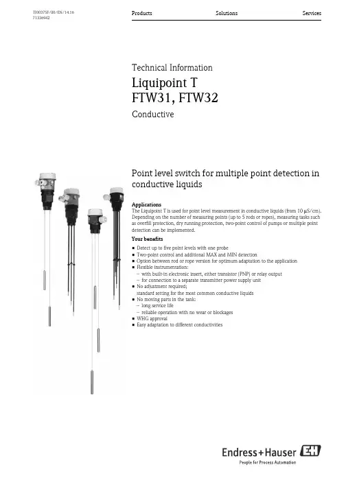
Products Solutions Services TI00375F/00/EN/14.1671336942Technical InformationLiquipoint TFTW31, FTW32ConductivePoint level switch for multiple point detection inconductive liquidsApplicationsThe Liquipoint T is used for point level measurement in conductive liquids (from 10 S/cm).Depending on the number of measuring points (up to 5 rods or ropes), measuring tasks suchas overfill protection, dry running protection, two-point control of pumps or multiple pointdetection can be implemented.Your benefits•Detect up to five point levels with one probe•Two-point control and additional MAX and MIN detection•Option between rod or rope version for optimum adaptation to the application•Flexible instrumentation:–with built-in electronic insert, either transistor (PNP) or relay output–for connection to a separate transmitter power supply unit•No adjustment required;standard setting for the most common conductive liquids•No moving parts in the tank:–long service life–reliable operation with no wear or blockages•WHG approval•Easy adaptation to different conductivitiesLiquipoint T FTW31, FTW322Endress+HauserTable of contentsFunction and system design. . . . . . . . . . . . . . . . . . . . .3Measuring principle . . . . . . . . . . . . . . . . . . . . . . . . . . . . . . . . . . . 3Measuring system . . . . . . . . . . . . . . . . . . . . . . . . . . . . . . . . . . . . . 3Input . . . . . . . . . . . . . . . . . . . . . . . . . . . . . . . . . . . . . .5Measured variable . . . . . . . . . . . . . . . . . . . . . . . . . . . . . . . . . . . . 5Measuring range (application) . . . . . . . . . . . . . . . . . . . . . . . . . . . . 5Input signal . . . . . . . . . . . . . . . . . . . . . . . . . . . . . . . . . . . . . . . . . 5Output. . . . . . . . . . . . . . . . . . . . . . . . . . . . . . . . . . . . .5Electronic insert FEW52 (DC-PNP) . . . . . . . . . . . . . . . . . . . . . . . 5Electronic insert FEW54 (relay) . . . . . . . . . . . . . . . . . . . . . . . . . . 6Electronic insert FEW58 (NAMUR) . . . . . . . . . . . . . . . . . . . . . . . 8Cable monitoring . . . . . . . . . . . . . . . . . . . . . . . . . . . . . . . . . . . . . 8Power supply. . . . . . . . . . . . . . . . . . . . . . . . . . . . . . . .9Compact instrument version with FEW52 . . . . . . . . . . . . . . . . . . 9Compact instrument version with FEW54 . . . . . . . . . . . . . . . . . 10Compact instrument version with FEW58 . . . . . . . . . . . . . . . . . 11Separate instrumentation for probes with two rodsor ropes with cable monitoring . . . . . . . . . . . . . . . . . . . . . . . . . . 11Separate instrumentation for probes with three rodsor ropes with cable monitoring . . . . . . . . . . . . . . . . . . . . . . . . . . 12Separate instrumentation for probes with five rodsor ropes with cable monitoring . . . . . . . . . . . . . . . . . . . . . . . . . . 12Cable entry . . . . . . . . . . . . . . . . . . . . . . . . . . . . . . . . . . . . . . . . 13Cable specifications . . . . . . . . . . . . . . . . . . . . . . . . . . . . . . . . . . 13Performance characteristics. . . . . . . . . . . . . . . . . . . .13Reference operating conditions . . . . . . . . . . . . . . . . . . . . . . . . . . 13Measuring error . . . . . . . . . . . . . . . . . . . . . . . . . . . . . . . . . . . . . 13Non-repeatability . . . . . . . . . . . . . . . . . . . . . . . . . . . . . . . . . . . . 13Hysteresis . . . . . . . . . . . . . . . . . . . . . . . . . . . . . . . . . . . . . . . . . . 13Switch-on delay . . . . . . . . . . . . . . . . . . . . . . . . . . . . . . . . . . . . 13Influence of ambient temperature . . . . . . . . . . . . . . . . . . . . . . . . 13Installation. . . . . . . . . . . . . . . . . . . . . . . . . . . . . . . . .13Mounting location . . . . . . . . . . . . . . . . . . . . . . . . . . . . . . . . . . . 13Orientation of probes . . . . . . . . . . . . . . . . . . . . . . . . . . . . . . . . . 14Example applications . . . . . . . . . . . . . . . . . . . . . . . . . . . . . . . . . 14Environment . . . . . . . . . . . . . . . . . . . . . . . . . . . . . . .15Ambient temperature range . . . . . . . . . . . . . . . . . . . . . . . . . . . . 15Storage temperature . . . . . . . . . . . . . . . . . . . . . . . . . . . . . . . . . . 15Climate class . . . . . . . . . . . . . . . . . . . . . . . . . . . . . . . . . . . . . . . 15Degree of protection . . . . . . . . . . . . . . . . . . . . . . . . . . . . . . . . . . 15Shock resistance . . . . . . . . . . . . . . . . . . . . . . . . . . . . . . . . . . . . . 15Vibration resistance (at min. rod length) . . . . . . . . . . . . . . . . . . . 15Electromagnetic compatibility . . . . . . . . . . . . . . . . . . . . . . . . . . . 15Process . . . . . . . . . . . . . . . . . . . . . . . . . . . . . . . . . . .16Conductivity . . . . . . . . . . . . . . . . . . . . . . . . . . . . . . . . . . . . . . . 16Limiting medium pressure range . . . . . . . . . . . . . . . . . . . . . . . . 16Environment . . . . . . . . . . . . . . . . . . . . . . . . . . . . . . . . . . . . . . . 16Mechanical construction . . . . . . . . . . . . . . . . . . . . . .17Weights . . . . . . . . . . . . . . . . . . . . . . . . . . . . . . . . . . . . . . . . . . . 17Material . . . . . . . . . . . . . . . . . . . . . . . . . . . . . . . . . . . . . . . . . . . 17Fitted electrodes . . . . . . . . . . . . . . . . . . . . . . . . . . . . . . . . . . . . 18Human interface . . . . . . . . . . . . . . . . . . . . . . . . . . . .19Operating elements . . . . . . . . . . . . . . . . . . . . . . . . . . . . . . . . . . 19Display elements . . . . . . . . . . . . . . . . . . . . . . . . . . . . . . . . . . . . 19Certificates and approvals . . . . . . . . . . . . . . . . . . . . .20CE mark . . . . . . . . . . . . . . . . . . . . . . . . . . . . . . . . . . . . . . . . . . 20Overfill protection . . . . . . . . . . . . . . . . . . . . . . . . . . . . . . . . . . . 20Other standards and guidelines . . . . . . . . . . . . . . . . . . . . . . . . . . 20RoHS . . . . . . . . . . . . . . . . . . . . . . . . . . . . . . . . . . . . . . . . . . . . . 20RCM-Tick marking . . . . . . . . . . . . . . . . . . . . . . . . . . . . . . . . . . 20Ex-approvals . . . . . . . . . . . . . . . . . . . . . . . . . . . . . . . . . . . . . . . 20Type of protection . . . . . . . . . . . . . . . . . . . . . . . . . . . . . . . . . . . 20Ordering information. . . . . . . . . . . . . . . . . . . . . . . . .21Ordering information . . . . . . . . . . . . . . . . . . . . . . . . . . . . . . . . . 21Accessories . . . . . . . . . . . . . . . . . . . . . . . . . . . . . . . .21Liquipoint T . . . . . . . . . . . . . . . . . . . . . . . . . . . . . . . . . . . . . . . 21Documentation . . . . . . . . . . . . . . . . . . . . . . . . . . . . .22Operating Instructions. . . . . . . . . . . . . . . . . . . . . . . . . . . . . . . . 22Certificates . . . . . . . . . . . . . . . . . . . . . . . . . . . . . . . . . . . . . . . . 22Liquipoint T FTW31, FTW32Function and system designMeasuring principle An alternating voltage exists between the probe rods. As soon as a conductive liquid creates a connectionbetween the ground probe rod and, for example, the MAX probe rod, a measurable current flows and theLiquipoint T switches.With point level detection, the device switches back as soon as the liquid clears the MIN probe.With two-point control, the device does not switch back until the MAX and MIN probe is cleared.Using alternating voltage prevents corrosion of the probe rods and electrolytic destruction of the product.The material used for the tank walls is not relevant for measurement because the system is designed as a closed,potential-free circuit between the probe rods and the electronics.There is absolutely no danger if the probe rods are touched during operation.Measuring system Probes without an integrated electronic insert (separate instrument version) forone- or two-point detectionThe measuring system consists of:• FTW31, FTW32 with two/three rods or ropes• One or two Nivotester FTW325• Control units, switches or signal transmitters, e.g. process control systems PLC, relays, etc.Switch points, depending on the tank materialEndress+Hauser3Liquipoint T FTW31, FTW324Endress+HauserProbes without integrated electronic insert for multiple point detection The measuring system consists of:• FTW31, FTW32 with five rods or ropes • Two or three Nivotester FTW325• Control units, switches or signal transmitters, e.g. process control systems PLC, relays, etc.Switch points, depending on the tank materialProbes with integrated electronic insert (compact instrument version)The measuring system consists of:• FTW31 with rods or FTW32 with ropes and an electronic insert• Control units, switches or signal transmitters, e.g. process control systems PLC, relays, etc.Independent of the tank material!Note!The compact instrument version with three rods or ropes is always operated in s mode.Liquipoint T FTW31, FTW32Endress+Hauser 5InputMeasured variableResistance change between two conductors caused by the presence or absence of a conductive liquid.Measuring range (application)The measuring range is dependent on the mounting location of the probes.Rod probes can have a max. length of 4 m (13 ft), and rope probes can have a max. length of 15 m (49 ft). Input signalProbes covered => a measurable current is flowing between the probes.Probes uncovered => there is no measurable current flowing between the probes.OutputElectronic insert FEW52 (DC-PNP)Output signalThree-wire direct current versionPreferred in conjunction with programmable logic controllers (PLC). Positive signal at the switch output of the electronics (PNP).The output is blocked after the point level is reached.*1 = Load current (connected); *2 Residual current (disconnected); *3 LED not lit; *4 LED lit See also "Output signal" ä5.If the probe is covered and the red LED flashes continuously, the sensitivity setting is too high. To ensure a safe switch status even if the conductivity of the medium varies slightly, reduce the sensitivity setting. Fail-safe modeSelecting the correct fail-safe mode ensures that the output always runs in quiescent current fail-safe.•MAX fail-safe mode (MAX): The output voltage is 0 V if the switch point is exceeded (probe covered), a fault occurs or the power supply fails.•MIN fail-safe mode (MIN): The output voltage is 0 V if the switch point is undershot (probe uncovered), a fault occurs or the power supply fails.Switching delayA switching delay of 2.0 s can be activated or deactivated via a DIL switch.If the switching delay is set to 0 s, the device switches after approx. 0.3 s.Liquipoint T FTW31, FTW326Endress+HauserSensitivityThe device operates in one of four sensitivity levels (100 Ω, 1 k Ω, 10 k Ω or 100 k Ω). The sensitivity level is set using two DIL switches (SENS). Setting on delivery: 100 k Ω (maximum sensitivity).Signal on alarmIn the event of a power failure or a damaged probe: < 100 μA Load•Load is switched via a transistor (PNP).•Cycled overload and short-circuit protection, continuous ≤200 mA (short-circuit proof) •Residual voltage at transistor at I max : <2.9 VElectronic insert FEW54 (relay)Output signalAC/DC connection with relay output Both relay contacts switch simultaneously.*1 = Relay energized; *2 Relay de-energized; *3 LED not lit; *4 LED lit See also "Power supply" →ä9.If the probe is covered and the red LED flashes continuously, the sensitivity setting is too high. To ensure a safe switch status even if the conductivity of the medium varies slightly, reduce the sensitivity level.Liquipoint T FTW31, FTW32Fail-safe modeSelecting the correct fail-safe mode ensures that the relay always runs in quiescent current fail-safe.•MAX safety (MAX): The relay de-energizes when the switch point is exceeded.(probe covered), a fault occurs or the power supply fails.•MIN safety (MIN): The relay de-energizes when the switch point is undershot.(probe uncovered), a fault occurs or the power supply fails.SensitivityThe device operates in one of four sensitivity levels (100 Ω, 1 kΩ, 10 kΩ or 100 kΩ).The sensitivity level is set using 2 DIL switches (SENS).Setting on delivery: 100 kΩ (maximum sensitivity)Switching delayA switching delay of 2.0 s can be activated or deactivated via a DIL switch.If the switching delay is set to 0 s, the device switches after approx. 0.3 s.Signal on alarmOutput signal in the event of a power failure or a damaged probe: relay de-energized.LoadLoads are switched via 2 potential-free change-over contacts.I~ max. 4 A, U~ max. 253 V;P~ max. 1000 VA, cos ϕ = 1, P~ max. 700 VA, cos ϕ > 0.7;I– max. 4 A to 30 V, I– max. 0.2 A to 150 V.When connecting a functional extra-low voltage circuit with double insulation in accordance withIEC 1010: the sum of the relay output and power supply voltages is max. 300 V.Galvanic isolationAll input channels, output channels and relay contacts are galvanically isolated from each other. Endress+Hauser7Liquipoint T FTW31, FTW328Endress+HauserElectronic insert FEW58 (NAMUR)Output signalFor connecting to isolating amplifiers acc. to NAMUR (IEC 60947-5-6) e.g. Nivotester FTL325N from Endress+Hauser.Output signal jump from high to low current on point level (H-L edge).Fail-safe modeSelecting the correct fail-safe mode ensures that the relay always runs in quiescent current fail-safe.•MAX safety (MAX): The output signal is <1.0 mA when the switch point is exceeded (probe covered), a fault occurs or the power supply fails.•MIN safety (MIN): The output signal is <1.0 mA when the switch point is undershot (probe uncovered), a fault occurs or the power supply fails.SensitivityThe device operates in one of four sensitivity levels (100 Ω, 1 k Ω, 10 k Ω or 100 k Ω).The sensitivity level is set using two DIL switches (SENS). Setting on delivery: 100 k Ω (maximum sensitivity)Switching delayA switching delay of 2.0 s can be activated or deactivated via a DIL switch.If the switching delay is set to 0 s, the device switches after approx. 0.3 s.LoadRefer to the "Technical Data" of the connected isolating amplifier acc. to NAMUR (IEC 60947-5-6)Cable monitoringFor probes without an electronic insert, an additional printed circuit board is installed in the housing to enable cable monitoring. It is always switched or connected between rod/rope 1 and 2.!Note!When using switching units (transmitters) that do not support cable monitoring, these must be removed.L00-FTL5xxxx-07-05-xx-xx-002= lit = flashes = unlitLiquipoint T FTW31, FTW32Endress+Hauser 9Power supplyCompact instrument version with FEW52Transistor circuit for loadThe load connected to terminal 3 is switched by a transistor, contactless and therefore without bouncing. In normal switch status, terminal 3 has a positive signal.The transistor is blocked in the event of a level alarm or a power failure.Protection against voltage peaksWhen connecting a device with high inductance, always connect a voltage limiter.Connecting the FEW52 electronic insert F: Fine-wire fuse 500 mA, semi-time lag M: Ground connection to protective earthSupply voltage (FEW52)•Supply voltage: U= 10.8 V to 45 V •Load connection: open collector; PNP •Switching voltage: max. 45 V•Connected load, continuous: max. 200 mA •Protected against reverse polarityPower consumption P < 1.1 WCurrent consumption I < 25 mA (without load)Liquipoint T FTW31, FTW3210Endress+HauserCompact instrument version with FEW54Relay contact circuit for loadThe connected load is switched via potential-free relay contacts (change-over contact).In the event of a level alarm or a power failure, the relay contacts break the connections between terminals 3 and 4 and terminals 6 and 7. The relays always switch simultaneously.Protection against voltage peaks and short-circuitsWhen connecting a device with high inductance, fit a spark barrier to protect the relay contact. A fine-wire fuse (load-dependent) can protect the relay contact in the event of a short-circuit.L00-FTW3xxxx-04-05-xx-en-002Connecting the FEW54 electronic insert F 1: Fine-wire fuse 500 mA, semi-time lagF 2: Fine-wire fuse to protect the relay contact, load-dependent M: Ground connection to protective earth (PE)Supply voltage (FEW54)•Supply voltage: U % 20 V to 55 V DC or U~ 20 V to 253 V AC, 50/60 Hz •Peak inrush current: max. 2 A, max. 400 μs •Output: two potential-free change-over contacts•Contact load capacity: U~ max. 253 V, I~ max. 4 A, U % 30 V/4 A; 150 V/ 0.2 APower consumption P < 2.0 WCurrent consumption I <60 mACompact instrument version with FEW58To be used with a separate switching unit acc. to IEC 60947-5-6 (NAMUR) e.g. Nivotester FTL325N from Endress+Hauser; Output signal jump from high to low current on point level (H-L edge).Signal transmission on a two-wire line:H-L-edge 2.2 to 6.5 mA / 0.4 to 1.0 mAWhen using a multiplex the cycle time must be set to a minimum of 2 s.Connecting the FEW58 electronic insertSupply voltage (FEW58)Refer to the "Technical Data" of the connected isolating amplifier acc. to IEC 60947-5-6 (NAMUR) e.g. Nivotester FTL325N from Endress+Hauser.Signal on alarmOutput signal with damaged sensor: < 1.0 mASeparate instrumentation forprobes with two rods or ropeswith cable monitoring*1Printed circuit board for cable monitoring (only required for probes with WHG certification.)The power supply and evaluation are provided by switching units, e.g. Nivotester FTW325Separate instrumentation forropes with cable monitoring*1Printed circuit board for cable monitoring (only required for probes with WHG certification.)The power supply and evaluation are provided by a switching unit, e.g. Nivotester FTW325Separate instrumentation for Array probes with five rods or ropeswith cable monitoring*1Printed circuit board for cable monitoring (only required for probes with WHG certification.)The power supply and evaluation are provided by a switching unit, e.g. Nivotester FTW325Cable entry M 20x1.5 and NPT 1/2 "•Quantity in F24 housing: 1 (separate instrument version)•Quantity in F16 housing: 2 (compact instrument version)•Conductor cross-section (including wire end sleeve): 2.5 mm² (14 AWG) Cable specifications Use a commercially available cable (25 Ω per wire).Performance characteristics!Note!When electronic insert is installed!Reference operating conditions •Ambient temperature: 23 °C (73 °F)•Medium temperature: 23 °C (73 °F)•Medium viscosity: medium must release the probe again (drain off). •Medium pressure p e: 0 bar (0 psi)•Probe installation: vertically from aboveMeasuring error±10 % at 100 Ω - 100 kΩ±5 % at 1 kΩ - 10 kΩNon-repeatability±5 % at 100 Ω - 100 kΩ±1 % at 1 kΩ - 10 kΩHysteresis– 10% for the MAX probe, in reference to the switch point. ∆s function disabled. Switch-on delay< 3 sInfluence of ambienttemperature< 0.05 %/KInstallationMounting location TanksThe rod and rope probes are mounted predominantly in tanks.Piping (partially filled)Two-rod probes can be used in piping as, for example, dry running protection for pumps.Orientation of probes Point level detectionExample applications Point level detection: Two-point control (∆s)Two-point control (∆s) e.g. pump controlPoint level detection: MAX and MIN detectionPoint level detection (MAX),MAX and MIN detection for compact instrument version only possible with s.EnvironmentAmbient temperature range Non-hazardous area•–40 to 70 °C (–40 to 158 °F)•–40 to 60 °C (–40 to 140 °F) for FEW58 NAMURStorage temperature–40 to 80 °C (–40 to 176 °F)Climate class Tropicalized as per DIN EEC 68, part 2-38Degree of protection IP66Shock resistance Practical testDIN 60068-2-64 / IEC 68-2-64: 20 to 2000 Hz, 1 (m/s2)2/HzVibration resistance(at min. rod length)Electromagnetic compatibility•Interference Emission to EN 61326, Electrical Equipment Class BInterference Immunity to EN 61326, Annex A (Industrial)•Use for separate-instrumented probes a screened cable between the probe and the switching unit.For installation instructions for screened cables and general instructions for EMC inspection conditions forE+H devices, see also TI00241F.ProcessConductivity 10 μS–1 to 10 bar (–1 psi)Limiting medium pressurerangeEnvironment Permissible ambient temperature T1 at the housing as a function of the measuring material temperature T2 inthe vessel:!Note!For separately instrumented devices (without FEW5x) there are no restrictions in the indicated temperaturerange.Mechanical construction!Note!All dimensions in mm (in)!WeightsMaterial Wetted •Seal between probe rod/probe rope and process connection: EPDM •Spacer: PP•Flat seal for process connection: elastomer fiber, (asbestos-free)•Process connections: –G 1 ½: PPS –NPT 1 ½: PPSProbe rods•Rod: 316L (1.4404) or carbon fiber •Insulation: PP Probe ropes•Rope: 316Ti (1.4571)•Insulation: FEP•Weight: 316L (1.4435)Separate instrument version2, 3 or 5 probesRod 1 m (3.3 ft) length 415 g, 530 g, 760 g (14.64 oz, 18.69 oz, 26.81 oz)Rope 1 m (3.3 ft) length 390 g, 470 g, 640 g (13.76 oz, 16.58 oz, 22.57 oz)Compact instrument version2 or3 probesRod 1 m (3.3 ft) length 600 g, 720 g (21.16 oz, 25.40 oz)Rope 1 m (3.3 ft) length710 g, 800 g (25.04 oz, 28.22 oz)Not wetted•Plastic housing F24 (separate instrument version)–Housing: PPS–Cover: PBT•Polyester housing F16: PBT-FR with PBT-FR cover or with PA12 transparent cover,–Cover seal:EPDM–Adapter: PBT-FR–Nameplate, glued: polyester foil (PET)–Pressure compensation filter: PBT-GF20•Ground terminal on housing (outside): 304 (1.4301)•Cable gland: polyamide (PA)Fitted electrodes Rod probesCompact instrument version: 2 or 3 rods; Separate instrument version: 2, 3 or 5 rods•Diameter without insulation: 4 mm (0.16 in)•Maximum rod length: 4000 mm (157 in)•Minimum rod length: 100 mm (3.94 in)•Thickness of insulation: 0.5 mm (0.02 in)•Length of non-insulated area (tip of rod): 20 mm (0.79 in)•Extraction forces (parallel probe rod): 1000 N (224.8 lbf)Rope probesCompact instrument version: 2 or 3 rods; Separate instrument version: 2, 3 or 5 rods•Diameter without insulation: 1 mm (0.04 in)•Maximum rope length: 15000 mm (591 in)•Minimum rope length: 250 mm (9.84 in)•Thickness of insulation: 0.75 mm (0.03 in)•Weight length: 100 mm ( 3.94 in) not insulated•Weight diameter: 10 mm (0.39 in)•Extraction forces (parallel probe rod): 500 N (112.4 lbf)Human interfaceOperating elements FEW52, FEW54, FEW58One DIL switch for MIN or MAX safetyOne DIL switch for 0 s or 2 s switching delayTwo DIL switches for setting the sensitivity level 100 Ω, 1 kΩ, 10 kΩ or 100 kΩDisplay elements Separate instrument versionThe display elements are dependent on the connected switching unit.Compact instrument versionFEW52One red light emitting diode: fault message, switch statusOne green light emitting diode: operationL00-FTW3xxxx-07-05-xx-xx-001FEW54One red light emitting diode: fault message, switch statusOne green light emitting diode: operationL00-FTW3xxxx-07-05-xx-xx-002FEW58One yellow light emitting diode: fault message, switch statusOne green light emitting diode: operationL00-FTW3xxxx-07-05-xx-xx-003Certificates and approvalsCE mark The Liquipoint T meets the legal requirements of the EC directives. Endress+Hauser confirms that the devicehas been successfully tested by applying the CE mark.Overfill protection•WHG, leak test (leakage)Other standards and guidelines •Low voltage equipment directive (73/ 23/ EEC)•DIN EN 61010 part 1, 2001Safety regulations for electrical equipment for measurement, control and laboratory use Part 1: General requirements•EN 61326Electrical equipment for measurement, control and laboratory useEMC requirementsRoHS The measuring system complies with the substance restrictions of the Restriction on HazardousSubstances Directive 2011/65/EU (RoHS 2).RCM-Tick marking The supplied product or measuring system meets the ACMA (Australian Communications and MediaAuthority) requirements for network integrity, interoperability, performance characteristics as wellas health and safety regulations. Here, especially the regulatory arrangements for electromagneticcompatibility are met. The products are labelled with the RCM- Tick marking on the name plate.A0029561 Ex-approvals For further information, please contact your local Endress+Hauser Sales Center.All data relevant to explosion protection can be found in separate Ex documentation(see: Documentation ä22) .Type of protection•[EEx ia] IIC (FEW58)•[EEx na/C(L)] IIC (FEW52, FEW54)Liquipoint T FTW31, FTW32Ordering informationOrdering information Detailed ordering information is available as follows:•In the Product Configurator on the Endress+Hauser website: ➞ Select country ➞Instruments ➞ Select device➞ Product page function: Configure this product•From your Endress+Hauser sales center: /worldwideProduct Configurator - the tool for individual product configuration•Configuration data updated on a daily basis•Depending on the device: Direct input of data specific to measuring point, such as measuring range oroperating language•Automatic verification of exclusion criteria•Automatic generation of order code with breakdown in PDF or Excel output format•Possibility to order directly from the Endress+Hauser online shopAccessoriesLiquipoint T Lock nut G 1 1/2"•Hexagon: AF 60•Material: PC-FR•Part number: 52014146Electronic insert FEW52•Output PNP 10.8 to 45 V DC•Part number: 52017271Electronic insert FEW54•Output relay 20 to 253 V AC, 20 to 55 V DC•Part number: 52017272Electronic insert FEW58•Output NAMUR (IEC 60947-5-6)•Part number: 52017273Endress+Hauser21Liquipoint T FTW31, FTW3222Endress+HauserDocumentation !Note! This documentation can be found on the product pages at "".Operating InstructionsLiquipoint T FTW31, FTW32 KA00204F/00Certificates WHG•Liquipoint T FTW31, FTW32ZE00043F/00ATEX II 3G EEx nA/C(L) IIC T6•Liquipoint T FTW31, FTW32XA00226F/00ATEX II 2G EEx ia IIC T6•Liquipoint T FTW31, FTW32XA00230F/00Liquipoint T FTW31, FTW32Endress+Hauser2371336942。
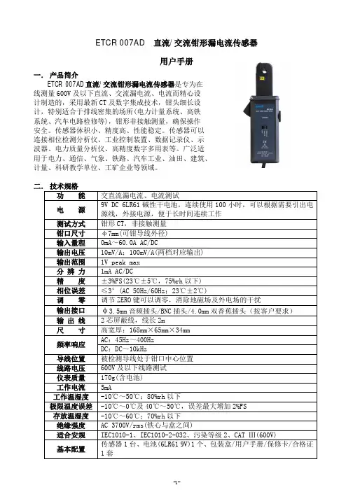
ETCR 007AD 直流/交流钳形漏电流传感器用户手册一. 产品简介ETCR 007AD 直流/交流钳形漏电流传感器是专为在线测量600V 及以下直流、交流漏电流、电流而精心设计制造的,采用最新CT 及数字集成技术,钳头细长设计,特别适合于排线密集的场所(电力计量系统、高铁系统、汽车电路检修等),钳形非接触测量,确保操作安全。
传感器体积小、精度高、性能稳定。
传感器可以连接相位检测分析仪、工业控制装置、数据记录仪、示波器、电力质量分析仪、高精度数字多用表等。
广泛适用于电力、通信、气象、铁路、汽车工业、油田、建筑、计量、科研教学单位、工矿企业等领域。
二. 技术规格功 能 交直流漏电流、电流测试电 源 9V DC 6LR61碱性干电池,连续使用100小时,可以根据需要引出电源线,外接电源,便于长时间连续工作测试方式 钳形CT ,非接触测量钳口尺寸 φ7mm(可钳导线外径)输入量程 0mA ~60.0A AC/DC输出电压 10mV/A ;100mV/A(两档对应输出)输出范围 1V peak max分 辨 力 1mA AC/DC精 度 ±3%FS(23℃±5℃,75%rh 以下)相位误差 ≤3°(AC 50Hz/60Hz ;23℃±2℃)调 零 调节ZERO 键可以调零,消除地磁场及外电场的干扰输出接口 φ3.5mm 音频插头/BNC 插头/4.0mm 双香蕉插头(按客户要求) 输 出 线 2芯屏蔽线,线长2m尺 寸 高宽厚:168mm ×65mm ×34mm频率响应 AC :45Hz ~400Hz DC :DC ~10kHz导线位置 被检测导线处于钳口中心位置线路电压 600V 及以下线路测试仪表质量 170g(含电池)工作电流 5mA工作温湿度 -10℃~50℃;80%rh 以下极限温度误差 -10℃~0℃及40℃~50℃,误差最大增加2%FS存放温湿度 -10℃~60℃;70%rh 以下绝缘强度 AC 3700V/rms(铁心与盒之间)适合安规 IEC1010-1、IEC1010-2-032、污染等级2、CAT Ⅲ(600V)基本配置 传感器1台、电池(6LR61 9V)1个、包装盒/用户手册/保修卡/合格证1套三.原理及结构采用分割式铁芯和霍尔元件(hole element)组合,能同时检测交流和直流漏电流、电流,当被测电流I通过传感器时,霍尔元件感应输出一个霍尔电压V H,可以通过检测霍尔电压V H,来计算被测试电流I,霍尔电压V H比例于被测试电流I。
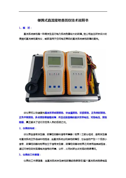
便携式直流接地查找仪技术说明书1、概述:直流系统接地是一种易发生且对电力系统危害较大的故障。
我公司自主研发设计的便携式直流接地查找仪,能够适用于任何电压等级的直流系统接地故障的查找。
该仪表可以快速查找直流系统间接接地、非金属接地、环路接地、正负同时接地、正负平衡接地、多点接地等疑难故障,并且还能准确的显示系统电压、对地电压、接地阻值,真正解决了运行及检修人员的后顾之忧。
2、仪表的构成:该仪表由信号发生器、故障检测器和信号采集器(钳表)三部分组成,信号发生器与直流系统正负母线和地相连,当直流系统出现接地故障后,它会自动产生一个低频小信号,故障检测器与钳表独立于信号发生器,故障检测器与钳表之间使用连接线相连,通过对待检测支路漏电流信号的采集、分析,从而判断出该支路的绝缘情况。
3、仪表的工作原理:仪表的工作原理是:当直流系统发生接地故障或绝缘降低(整个直流系统绝缘电阻小于报警整定值),直流系统电压监测仪表发出警报时,将信号发生器接入直流系统的正、负母线和地之间。
信号发生器自动判断直流系统电压等级,自动判断接地故障的极性、接地程度,自动分析绝缘监测平衡电桥回路接线方式和平衡电桥电阻大小,形成信号输出的智能反馈,向直流正负母线和地间,发射适宜系统检测,对系统无影响的低频信号,并实时显示系统电压、正对地电压、负对地电压和系统对地绝缘总阻抗。
故障检测器检测各回路对地绝缘的直流信号漏电流,并模拟显示接地回路绝缘状态,判断出接地故障回路(支路),并继续沿故障回路(支路)检测出接地故障,将故障点准确定位。
信号发生器、故障检测器均采用微计算机技术,具有集成程度高,判断速度快,检测灵敏度高、抗干扰能力强、故障定位准确等特点。
在软件处理上利用了模糊控制理论和通信的噪声理论,并依据直流系统的特点优化了算法,即使系统有大分布电容的干扰、电磁脉冲干扰和其它噪声干扰的影响,也能准确地判断出接地故障点,为接地故障的查找提供了有力的保障。

漏电流测试仪使用说明书(总10页)--本页仅作为文档封面,使用时请直接删除即可----内页可以根据需求调整合适字体及大小--漏电流测试仪使用说明书一、操作说明使用本仪器之前建议用户阅读一下本技术说明书,了解熟悉本仪器的使用方法和工作原理。
仪器在接通电源之前,应将电压调节旋钮向左旋至最小,工作选择按钮置于放电位置,否则电压输出接线柱与外壳间有极化电压输出,会使连接测试夹具时触电。
在使用仪器过程中,转换电压量程开关时,注意要将电压调节旋钮向左旋至最小,以免电压表受冲击而损坏。
1、面板上各器件之功能说明(1)右下角的电源开关按至ON位置即接通电源,此时相邻的绿色指示灯即有亮的指示。
(2)中间的电压调节旋钮是控制施加在被测电容器上的直流极化电压数值的,可以从电压表显示器上显示出来,其范围由其左边的电压量程开关决定。
其中TH2685C量程为0 ~50V/0 ~200V,TH2686C量程为0 ~200V/0 ~500V,TH2687C量程为0 ~200V/0~650V,TH2688C量程为0 ~25V/0~75V。
(3)右上的时控开关及时间拨盘是控制仪器内线路从充电自动转换至测试状态的延时时间,当时控开关处于OFF时,其时间拨盘不起作用,时间显示器无显示,此时测量即为手控测试。
当时控开关处于ON时,充电时间的计算是从被测电容器接上仪器进行充电的瞬间就自动算起的,面板右上的充电指示灯(黄色)是指示充电时间的。
时间显示窗口显示被测电容器充电时间的倒记数时间值,当时间窗口倒记数显示为0时,充电指示灯熄灭,仪器进入测试状态。
(4)右侧中间的置限开关及置限电位器是由于被测电容器漏电流分选而设置的,在正常测试时,置限开关处于OFF位置,当置限开关处于ON时,仪器则处于门限预置状态,此时仪器夹具上不应有任何被测元件,电流表指示出其预置电流值,结合电流量程开关,调节预置电流旋钮,将电流表的指针调到需要的预置数值上,以后在测试过程中,遇有漏电流超过这个门限值的,仪器的蜂鸣器立即鸣响,左边的不良指示灯即亮,以示超差。
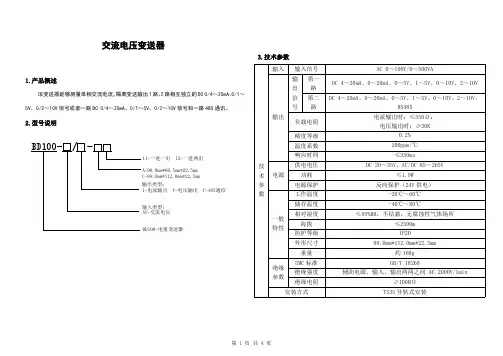
交流电压变送器1.产品概述该变送器能够测量单相交流电流,隔离变送输出1路、2路相互独立的DC 0/4~20mA、0/1~5V、0/2~10V 信号或者一路DC 0/4~20mA、0/1~5V、0/2~10V 信号和一路485通讯。
2.型号说明BD100- / -BD100-电量变送器输入类型: AV-交流电压11-一进一出 12-一进两出 I-电流输出 V-电压输出 C-485通信 A-98.0mm*66.5mm*22.5mm 输出类型:C-99.0mm*112.0mm*22.5mm3.技术参数技术参数输入输入信号AC 0~100V/0~500VA输出输出信号第一路DC 4~20mA、0~20mA、0~5V、1~5V、0~10V、2~10V 第二路DC 4~20mA、0~20mA、0~5V、1~5V、0~10V、2~10V,RS485负载电阻电流输出时:≤550Ω;电压输出时:≥30K精度等级0.2%温度系数200ppm/℃响应时间≤350ms电源供电电压DC 20~35V,AC/DC 85~265V功耗≤1.9W电源保护反向保护(24V 供电)一般特性工作温度-20℃~60℃储存温度-40℃~80℃相对湿度≤95%RH,不结露,无腐蚀性气体场所海拔≤2500m 防护等级IP20外形尺寸99.0mm*112.0mm*22.5mm重量约160g 绝缘参数EMC 标准GB/T 18268绝缘强度辅助电源、输入、输出两两之间AC 2000V/1min绝缘电阻≥100MΩ安装方式TS35导轨式安装4.外形及安装(单位:mm)BD100-AV/□-C12壳体尺寸图909911222.535.55.指示灯含义1.绿灯:上电后,电源1S闪烁一次。
RS485通讯连接成功后,50ms闪烁一次。
2.红灯:发生过压、过流时,红灯点亮(过压、过流报警值为满度信号的120%)。
6.接线方式注:仪表接线采用可拆卸的接线端子,导线采用横截面积为0.5mm²~2.5mm²屏蔽线。

漏电流测试仪使用说明书一、操作说明使用本仪器之前建议用户阅读一下本技术说明书,了解熟悉本仪器的使用方法和工作原理。
仪器在接通电源之前,应将电压调节旋钮向左旋至最小,工作选择按钮置于放电位置,否则电压输出接线柱与外壳间有极化电压输出,会使连接测试夹具时触电。
在使用仪器过程中,转换电压量程开关时,注意要将电压调节旋钮向左旋至最小,以免电压表受冲击而损坏。
1、面板上各器件之功能说明(1)右下角的电源开关按至ON位置即接通电源,此时相邻的绿色指示灯即有亮的指示。
(2)中间的电压调节旋钮是控制施加在被测电容器上的直流极化电压数值的,可以从电压表显示器上显示出来,其范围由其左边的电压量程开关决定。
其中TH2685C量程为0 ~50V/0 ~200V,TH2686C量程为0 ~200V/0 ~500V,TH2687C 量程为0 ~200V/0~650V,TH2688C量程为0 ~25V/0~75V。
(3)右上的时控开关及时间拨盘是控制仪器内线路从充电自动转换至测试状态的延时时间,当时控开关处于OFF时,其时间拨盘不起作用,时间显示器无显示,此时测量即为手控测试。
当时控开关处于ON时,充电时间的计算是从被测电容器接上仪器进行充电的瞬间就自动算起的,面板右上的充电指示灯(黄色)是指示充电时间的。
时间显示窗口显示被测电容器充电时间的倒记数时间值,当时间窗口倒记数显示为0时,充电指示灯熄灭,仪器进入测试状态。
(4)右侧中间的置限开关及置限电位器是由于被测电容器漏电流分选而设置的,在正常测试时,置限开关处于OFF位置,当置限开关处于ON时,仪器则处于门限预置状态,此时仪器夹具上不应有任何被测元件,电流表指示出其预置电流值,结合电流量程开关,调节预置电流旋钮,将电流表的指针调到需要的预置数值上,以后在测试过程中,遇有漏电流超过这个门限值的,仪器的蜂鸣器立即鸣响,左边的不良指示灯即亮,以示超差。
在置限过程中,不良指示灯亮及蜂鸣器报警是正常现象。
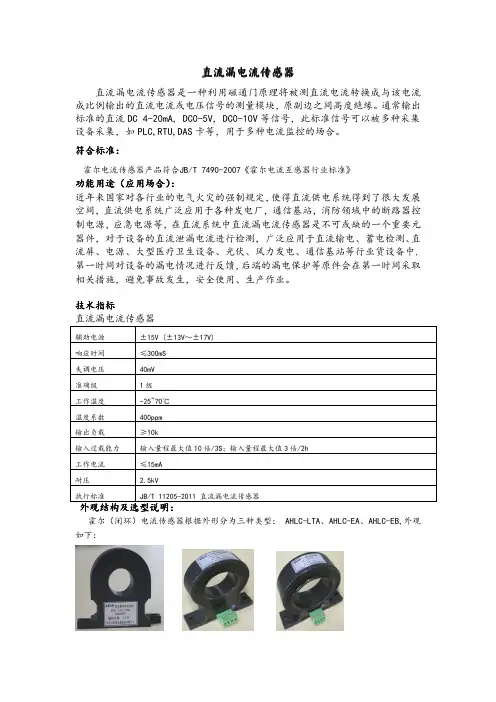
直流漏电流传感器直流漏电流传感器是一种利用磁通门原理将被测直流电流转换成与该电流成比例输出的直流电流或电压信号的测量模块,原副边之间高度绝缘。
通常输出标准的直流DC4-20mA,DC0-5V,DC0-10V等信号,此标准信号可以被多种采集设备采集,如PLC,RTU,DAS卡等,用于多种电流监控的场合。
符合标准:霍尔电流传感器产品符合JB/T7490-2007《霍尔电流互感器行业标准》功能用途(应用场合)):功能用途(应用场合近年来国家对各行业的电气火灾的强制规定,使得直流供电系统得到了很大发展空间,直流供电系统广泛应用于各种发电厂,通信基站,消防领域中的断路器控制电源,应急电源等,在直流系统中直流漏电流传感器是不可或缺的一个重要元器件,对于设备的直流泄漏电流进行检测,广泛应用于直流输电、蓄电检测、直流屏、电源、大型医疗卫生设备、光伏、风力发电、通信基站等行业货设备中,第一时间对设备的漏电情况进行反馈,后端的漏电保护等原件会在第一时间采取相关措施,避免事故发生,安全使用、生产作业。
技术指标直流漏电流传感器辅助电源±15V(±13V~±17V)响应时间≤300mS失调电压40mV准确级1级工作温度-25~70℃温度系数400ppm输出负载≥10k输入过载能力输入量程最大值10倍/3S;输入量程最大值3倍/2h工作电流≤15mA耐压 2.5kV执行标准JB/T11205-2011直流漏电流传感器外观结构及选型说明:霍尔(闭环)电流传感器根据外形分为三种类型:AHLC-LTA、AHLC-EA、AHLC-EB,外观如下:直流漏电流传感器安装方式环境要求:1、工作场所:无雨雪直接侵袭、无腐蚀性气体和剧烈震动的场所;2、工作环境温度:-25℃~+70℃;贮存环境温度:-40℃~+80℃;3、工作环境相对湿度:<95%RH,不结露;4、海拔高度:≤2000m;5、采用螺丝固定安装;6、接线端子采用绿色可插拔端子范例型号:AHLC-LTA辅助电源:DC ±15V输入:200mA输出:5V作者简介:戴金花,女,本科,江苏安科瑞电器制造有限公司,主要研究方向为电量传感器设计,Email:2880157871@ 手机:188********QQ:2880157871分类AHLC-LTAAHLC-EA AHLC-EB输入信号1010~~1000mA 1010~~1000mA 1010~~1000mA 输出信号5V 5V 5V。

直流系统接地故障检测仪目录一、概述 (2)二、工作原理 (3)三、技术指标 (5)四、仪器结构 (6)五、注意事项 (9)六、装箱清单 (10)附录1 (11)附录2 (12)一、概述本公司是专业从事电力系统高科技产品开发、生产、销售的产业一体化公司,公司自成立以来开发出便携式直流系统接地故障测试仪,该系列产品已在现场的大量应用中获得极大的成功,已经成为国内最成功的产品,广泛应用于全国各个省市。
本产品是新一代直流接地故障测试仪。
它能够适用于任何电压等级的直流系统,配备了高精度的检测钳表,通过对多种信号的高效处理大大提高了检测范围与抗干扰能力;采用了优秀的算法和先进的模糊控制计算理论,将被检测绝缘支路的优势程度以数值的形式表示出来,充分体现了人工智能的优越性;对于接地点位置的断定,它们更是拥有准确的判断力,每次检测都能够指出接地点位置及方向。
本装置以系统安全为首要前提,按行业标准的最高要求,以可靠的低频信号方式进行检测,并在现场进行了大量的实际应用,对系统无任何影响。
发电厂、变电站的直流系统为控制、保护、信号和自动装置提供电源,直流系统的安全连续运行对保证发供电有着极大的重要性。
由于直流系统为浮空制的不接地系统,如果发生两点接地,就可能引起上述装置误动、拒动,从而造成重大事故。
因此当发生一点接地时,就应在保证直流系统正常供电的同时准确迅速地探测出接地点,排除接地故障,从而避免两点接地可能带来的危害。
本产品用于在不断电情况下查找发电厂、变电站直流系统接地点的准确位置。
各种类型的接地故障,均能迅速地查找出接地点,准确率达到100%。
本仪器与国内外同类型的仪器相比具有以下优点:1、使用简单。
本仪器只需打开电源开关就可直接使用,无需别的按键操作。
2、安全可靠。
本仪器无需停浮充电机及其它电源,对直流系统没有任何影响。
3、适用电压等级多。
直流系统220V、110V、48V、24V都可以使用。
4、适用范围广。
任何类型电厂、变电站、煤矿、化工厂等供电部门都可使用。
HDT1直流接地测试装置使用说明书北京京航智汇科技有限公司版本号:V2.0目录1 概述 (1)1.1 适用范围 (1)1.2 型号说明 (1)1.3技术指标 .................................................................................. 错误!未定义书签。
2 工作原理及主要功能.......................................................................... 错误!未定义书签。
2.1 工作原理.................................................................................. 错误!未定义书签。
2.2 主要功能及特点介绍 ............................................................... 错误!未定义书签。
3 用户操作说明 (3)3.1 HDT1面板说明 (3)3.2 液晶显示界面 (3)4 机箱尺寸图 (12)4.1 机箱外观图 (12)4.2 机箱尺寸图 (12)1 概述1.1 适用范围目前国内已有上百家厂家数百种直流绝缘监测装置设备,其选线原理与方法也是各种各样,然而,不管是巡检装置还是便携装置,国内目前没有统一的检验标准,也没有检测手段,相关部门也不能定期对以上设备进行检验。
另外,各厂家在生产直流接地检测设备时,没有系统地进行功能性、安全性的检测,技术指标很不规范,用户选用产品时,仅凭各生产厂家宣传,没有可参考、对照的技术指标,因而难以选择到合符实际情况的产品。
由于以上种种原因,导致这些产品的实际应用中,接地告警电阻值是否准确不知道,接地选线也经常不正确,对系统安全运行埋下隐患。
综上,我公司研发出HDT1直流接地测试装置(以下简称HDT1),用于测试个内直流绝缘监测装置测,HDT1可模拟常见的直流接地故障、交流窜入直流系统故障,可对运行的直流绝缘监测装置、便携式接地查找装置、交流窜入直流监控装置等进行测试与校验,可用于供电部门、发电厂、生产厂家或教研单位。
漏电流传感器一、漏电流传感器的介绍信瑞达漏电流传感器依据互感器电磁隔离、磁调制工作原理将被测交流微电流、直流微电流转换成直流电流、直流电压并隔离输出标准模拟信号或数字信号的装置,执行标准:GB/T 13850-1998。
广泛应用于直流及交流供电系统的母线及各支路绝缘情况实时监测。
传感器通用技术条件:漏电流传感器的引用标准及规则是GB/T13850-1998,它的相对湿度是≤93%,准确度等级是0.5、1.0级,贮藏条件是温度-40~ 70℃相对湿度是20~90%,无凝露,工作温度是-10~55℃,平均无故障时间是≥80000h 。
二、漏电流传感器的原理:漏电流传感器用于直流mA级微小电流的隔离、穿孔式测量,可按用户需求定制不同可定制。
漏电流传感器环绕安装在直流回路的正负出线上,当装置运行时,实时检测各支路传感器输出的信号,当支路绝缘情况正常时,流过传感器的电流大小相等,方向相反,其输出信号为零;当支路有接地时,漏电流传感器有差流流过,传感器的输出不为零。
因此通过检测各支路传感器的输出信号,就可以判断直流系统接地支路。
该原理选线精度高,不受线路分布电容的影响。
三、漏电流传感器的应用漏电流传感器广泛适用于电力、通信、气象、铁路、油田、建筑、计量、科研教学单位、工矿企业等领域高精度、小相位误差的交流漏电流、电流、功率和电能测量,可连接各种高精度数字多用表或数据记录仪,使用非常方便。
四、漏电流传感器的分类LF系列漏电流传感器按照输入形式分为以下两大类:1.模拟量输出漏电流传感器2.数字量输出直流漏电流传感器五、szxrdt智能漏电流传感器简介szxrdt智能漏电流传感器是直流绝缘监测系统中重要组成部分之一,其环绕安装在直流回路的正负出线上,当装置运行时,实时检测各支路传感器输出的信号,当支路绝缘情况正常时,流过传感器的电流大小相等,方向相反,其输出信号为零;当支路有接地时,漏电流传感器有差流流过,传感器的输出不为零。
Application NoteF r o m t h e F l u k e D i g i t a l L i b r a r y @ w w w.f l u k e.c o m /l i b r a r yPower interruptions Unfortunately the unconditional availability of electrical power can never be taken for granted. In fact, quite frequently interrup-tions occur of various durations. Many of these pass unnoticed, but some may prevent your equipment from working prop-erly. The longest interrupts are obviously the ones that make all lights go down and all equip-ment stop. But sometimes, we see only a single piece of equip-ment blink as if the power has been interrupted, after which operation continues immediately with nothing else apparently indicating that anything has happened. This then raises ques-tion of whether the ‘hiccough’ was due to a power malfunction, or to the fact that the affected piece of equipment itself is faulty.An oscilloscope from the ScopeMeter 190 Series II can be a valuable tool in finding answers here, as it allows you to detect these short-duration interrupts of the electrical power system.Pulse width triggering ScopeMeter 190 Series II oscil-loscopes are equipped with a pulsewidth-trigger mode. This trigger mode is able to detect, for instance, the pulse width in Electrical energy is the driving force of today’s world. It is available almost everywhere you go, and is capable of driving all sorts of equipment from heating and cook-ing equipment, through motors and ventilators to the PC that this application note is written on. And it’s available all the time. Or is it?a repetitive signal. But it is also capable of detecting the absence of a signal for a certain amount of time, for instance of the mains voltage.When the oscilloscope is used to monitor the mains signal, an interruption will trigger the oscilloscope and the waveform information will be “frozen” in the oscilloscope’s memory. If more such events should occur, the scope screen will automati-cally be updated for each such event, and the successive events will be stored in the REPLAY-memory. The whole sequence of events can then be re-played and analyzed from the scope screen which also displays a date- and timestamp. The replay screens can be copied to a PC for documenting and archiving.Here’s a set-up that allows you to detect the moments that the mains voltage is interrupted.Instrument set-up The mains voltage is a sinusoidal ac voltage. This means that it is half the time positive and half the time negative. A full cycle takes 20 ms if the line frequency is 50 Hz, or 16.6 ms for 60 Hz systems.Given this ac voltage, we can set-up the ScopeMeter to detect if the mains voltage is inter-rupted. To do so, we set up the ScopeMeter to recognize the Measuring short interrupts on the mains with a Fluke ScopeMeter ®190 Series II absence of any voltage for longer than ¾ of a cycle, this is 15 ms (or 12.5 ms for a 60 Hz system), as this can only happen during an interrupt of the normal cycle.Connect the ScopeMeter probe to input A, and connect the probe ground clip (alligator) to the mains neutral. Connect the probe tip to the ‘live’ mains line. Be careful in making these connections as the mains system carries hazardous voltage! Use only the safety-designed acces-sories described with the Fluke ScopeMeter.Alternatively, if a low-voltage transformer is part of the system under test, measure on the low-voltage side of that transformer as this provides the necessary safety barrier.Select the ScopeMeter to work in ‘Scope’ mode, and make sure the instrument is in ‘Auto’ mode (see upper right corner of the screen). If it is not in ‘Auto’ mode,2 Fluke Corporation Measuring short interrupts on the mains with a ScopeMeter ® 190 Series II press the green AUTO/MANUAL button to set the indicator in the upper-right corner to read ‘Auto’. A continuous sinewave will now be visible. Change the time-base setting to give about 2 or3 cycles per horizontal division, so select 20 or 40 ms/div (see figure 1).Change the horizontal trigger position to a position to the right of the screen, e.g. at a position three divisions from the right side of the screen. Look at the ∫-symbol in Figure 1. A continu-ous sinewave will remain visible and is repeatedly refreshed on screen. The vertical position of the ∫-symbol marks the voltage level that the trigger system is responding to.Now select the ‘Trigger’ menu, and press F4 (Trigger options) and select “Pulse Width on A” from the menu. Press Enter. You will notice that a new menu layer appears. Select the negative oriented pulses (‘U’-shaped pulses) and the condition ‘Pulsewidth >t ’, select ‘Update on trigger’ in order to catch suc-cessive interrupts rather than only one.Press Enter until all selections are made, and the menu text is switched off again. The up and down controls (s and t) can now be used to change the time dura-tion of the interrupts that the scope will respond to. Set this to 15 ms (or 12.5 ms when working on a 60 Hz system). The oscil-loscope is now ready to respond to any short-term interrupt of the mains voltage.Figures 3 and 4 provide some examples of power interrupts that were captured.Conclusion Malfunctioning of electronic equipment is sometimes related to short-duration interrupts of the mains supply. This calls for a tool to find such interrupts, complete with date and time of occur-rence. Fluke ScopeMeter 190 Series II oscilloscopes are capa-ble of conveniently detecting and storing such power inter-rupts. Even if many such events occur over a longer period of time, up to 100 individual events can be stored, complete with date- and time-indicator, making longer-term power monitoring easier than ever.Fluke Corporation PO Box 9090, Everett, WA 98206 U.S.A.Fluke Europe B.V. PO Box 1186, 5602 BD Eindhoven, The NetherlandsFor more information call: In the U.S.A. (800) 443-5853 or Fax (425) 446-5116 In Europe/M-East/Africa +31 (0) 40 2675 200 or Fax +31 (0) 40 2675 222 In Canada (800)-36-FLUKE or Fax (905) 890-6866 From other countries +1 (425) 446-5500 or Fax +1 (425) 446-5116 Web access: ©2005-2011 Fluke Corporation. Specifications subject to change without notice. Printed in U.S.A. 4/2011 2543312B A-EN-N Pub_ID: 10616-eng, rev 01Modification of this document is not permitted without written permission from Fluke Corporation.Fluke. Keeping your worldup and running.Figure 1: 60 Hz mains voltage using AUTO-mode.Figure 2: Menu layer for pulse-width triggersettings.Figure 3: Power disruption due to a loosecontact in the wiring.Figure 4: Interrupt as stored in the replay-memory. Note the date- and time-markers that were automatically attached to the recording.。
CSA101-G050T01电流传感器使用说明书V1.1本手册为湖南银河电气有限公司产品电流传感器用户手册,本手册为用户提供安装调试、操作使用及日常维护的有关注意事项,在安装、使用前请仔细阅读。
本手册随产品一起提供,请妥善保管、以备查阅和维护使用。
声明我们非常认真的整理此手册,但我们对本手册的内容不保证完全正确。
因为我们的产品一直在持续的改良及更新,故我方保留随时修改本手册的内容而不另行通知的权利。
同时我们对不正确使用本手册所包含内容而导致的直接、间接、有意、无意的损坏及隐患概不负责。
安全操作知识◆产品使用前,请您务必仔细阅读用户手册。
◆需对产品进行搬动时,请您务必先断电并将与之相连的所有连接线缆等拔掉。
◆如果发现机壳、稳固件、电源线、连接线缆,或相连的设备有任何损坏,请您立即将装置与电源断开。
◆如果对设备的安全运行存在疑虑,应立即关闭设备和相应附件,并在最快时间内与本公司技术支持部门取得联系,沟通解决。
1.产品概述CSA101-G050T01是一种能在原边、副边完全隔离条件下测量直流、交流、脉冲以及各种不规则波形的电流传感器,它主要用于要求准确度高的计量检定和计量校准领域,以及要求高灵敏度、高稳定性和高可靠性的电能质量分析、功率分析仪、医疗、航空航天、导弹、舰艇等领域。
2.技术特点●极高的准确度●极好的线性度●极高的稳定性●极高的灵敏度●极高的分辨率●极低的温度漂移●极低的失调电流●极低的插入损耗●抗干扰能力强●响应速度快●极低的噪声●极小的角差●宽频带●模拟量输出3.应用场合●计量检定与校准●实验室电流测量●仪器仪表(如功率分析仪)●医疗设备(如核磁共振MRI)●电池组检测●电力控制●电源●舰船●新能源●轨道交通●航空航天●工业测量4.电气性能项目符号测试条件数值单位最小标称最大原边额定电流I PN-- -- ±100 -- Adc 测量范围I PM1分钟/小时-- -- ±120 Adc 工作电压V c全范围±12 -- ±15 Vdc 电流消耗I c I PM范围内±10 ±60 ±90 mA 电流变比K N输入:输出2000:1 -- 额定输出电流I SN原边额定电流--±50--mAVc:±12,I PN:±100 Adc 0 -- 50 Ω测量电阻R MVc:±15,I PN:±100 Adc 0 -- 100 Ω5.精度-动态参数项目符号测试条件数值单位最小标称最大精度X e输入直流,@25±20℃-- -- 0.02 % 线性度εL-- -- -- 20 ppm 零点失调电流I o25±10℃-- -- 5 uA 零点失调电流I oT全工作温度范围内-- -- 10 uA 响应时间t r-- -- -- 1 us 电流跟随速度di/dt -- 200 -- -- A/us 频带宽度(- 3 dB) F -- 0 -- 100 kHz6.一般特性项目符号测试条件数值单位最小标称最大工作温度范围T A-- -40 -- +85 ℃存储温度范围T S-- -45 -- +90 ℃质量m 58±5 g7.安全特性项目符号测试条件数值单位最小标称最大耐受电压原、副边之间副边与外壳之间V d50Hz,1min 5 kV瞬态隔离耐压原、副边之间V w50us 10 kV 相比漏电起痕指数CTI IEC-60112 275 V8.外形尺寸及端口定义8.1、外形尺寸(单位:mm)图1 外形图外形图说明:外形尺寸、安装定位尺寸公差按照GB/T1804-2000 C级标准执行。
多一漏电测试仪使用说明书
多一型漏电保护器测试仪,可丈量漏电保护器动作电流、分断时间:还可丈量沟通电压。
线路及设施漏电流等。
多一测试仪为90年XX省电力科技项目,产品标准参照GB6829-86等相关标准制定,经省级鉴定存案,编号xxxxxxx-xx。
本仪器采纳集成电路,体积小、功能多、正确度高、性能价钱比高,便于携带使用、能测试各样种类的漏电保护器。
测试结果以数字显示,直观,分辨力高,在测漏电保护器动作电流和分断时间时,操作只要几秒钟,显示结果自动暂存数秒钟后自动复零,操作极其方便。
本仪器丈量沟通电压范围宽,能合适任何低电压系统。
本仪器能检测线路漏电流以及用电设施在工作地点上总的漏电流。
在测漏电流时,方便安全靠谱,并有过流保护举措。
多一测试仪不需另接电源,只用一节9V叠层电池,就能连续工作200小时以上。
仪器配有包装兼工作背袋,可随身携带进行测试。
多一测试仪可宽泛应用于供电部门,农电部门,漏电保护器生产厂家,建筑、刊矿山、机床等行业的劳动安检部门以及广大电工。