麦克维尔高压离心机组技术交流
- 格式:ppt
- 大小:13.11 MB
- 文档页数:26
ED15063-2Group : Controls Part Number: ED 15063Date : December 2005Supersedes: ED15063-1© 2005 McQuay InternationalMicroTech II®Chiller Unit Controller Protocol InformationModbus ® Protocol• WSC Water-Cooled Centrifugal, Single-Compressor • WDC Water-Cooled Centrifugal, Dual-Compressor • WPV Water-Cooled Centrifugal, Single-Compressor• HSC Water-Cooled Single-Compressor Centrifugal, Heat Recovery • HDC Water-Cooled Dual-Compressor Centrifugal, Heat Recovery • TSC Water-Cooled Single-Compressor Centrifugal, Templifier • WMC Water-Cooled Centrifugal, Magnetic Bearing • WCC Water-Cooled Centrifugal, Counterflow • AGZ Air-Cooled Global Scroll• ACZ Air-Cooled Scroll Condensing Unit • WGZ Water-Cooled Global Scroll • AGS Air-Cooled Global Screw • WGS Water-Cooled Global ScrewTable of ContentsTABLE OF CONTENTS (2)L IMITED W ARRANTY (4)N OTICE (4)R EVISION H ISTORY (4)S OFTWARE R EVISION (4)R EFERENCE D OCUMENTS (4)INTRODUCTION (5)C HILLER M ODELS (5)C ONTROLLER D ATA P OINTS (5)MODBUS PROTOCOL INFORMATION (6)C OMPATIBILITY (6)P ROTOCOL D EFINITIONS (6)V ALID F UNCTION C ODES (6)V ALID E RROR C ODES (6)M ODBUS D ATA P OINT (7)E XAMPLE D ATA P OINT: C HILLER O N O FF (7)C ONFIGURING THE U NIT C ONTROLLER (7)TYPICAL APPLICATION: MINIMUM INTEGRATION (8)S ET UP THE U NIT FOR N ETWORK C ONTROL (8)D ISPLAY I MPORTANT D ATA P OINTS (8)COMPREHENSIVE DATA POINT TABLES (9)M ODBUS D ATA P OINTS (9)DETAILED DATA POINT INFORMATION (11)A CTIVE S ETPOINT (12)A CTUAL C APACITY (12)C APACITY L IMIT O UTPUT (12)C APACITY L IMIT S ETPOINT (12)C HILLER E NABLE (12)C HILLER L IMITED (12)C HILLER L OCAL/R EMOTE (13)C HILLER M ODE O UTPUT (13)C HILLER M ODE S ETPOINT (13)C HILLER O N O FF (13)C HILLER S TATUS (13)C OMPRESSOR C URRENT (13)C OMPRESSOR D ISCHARGE T EMPERATURE (14)C OMPRESSOR P ERCENT RLA (14)C OMPRESSOR P OWER (14)C OMPRESSOR R UN H OURS (14)C OMPRESSOR S ELECT (15)C OMPRESSOR S TARTS (15)C OMPRESSOR S UCTION L INE T EMPERATURE (15)C OMPRESSOR V OLTAGE (15)C ONDENSER E NTERING W ATER T EMPERATURE (16)C ONDENSER F LOW S WITCH S TATUS (16)C ONDENSER L EAVING W ATER T EMPERATURE (16)C ONDENSER P UMP R UN H OURS (16)C ONDENSER R EFRIGERANT P RESSURE (16)C ONDENSER S ATURATED R EFRIGERANT T EMPERATURE (16)2 ED 15063-2C ONDENSER W ATER F LOW R ATE (16)C ONDENSER W ATER P UMP S TATUS (17)C OOL S ETPOINT (17)E VAPORATOR E NTERING W ATER T EMPERATURE (17)E VAPORATOR F LOW S WITCH S TATUS (17)E VAPORATOR L EAVING W ATER T EMPERATURE FOR U NIT (17)E VAPORATOR L EAVING W ATER T EMPERATURE FOR C OMPRESSOR (17)E VAPORATOR P UMP R UN H OURS (17)E VAPORATOR R EFRIGERANT P RESSURE (18)E VAPORATOR S ATURATED R EFRIGERANT T EMPERATURE (18)E VAPORATOR W ATER F LOW R ATE (18)E VAPORATOR W ATER P UMP S TATUS (18)H EAT R ECOVERY E NTERING W ATER T EMPERATURE (18)H EAT R ECOVERY L EAVING W ATER T EMPERATURE (18)H EAT S ETPOINT (18)I CE S ETPOINT (19)L IQUID L INE R EFRIGERANT P RESSURE (19)L IQUID L INE R EFRIGERANT T EMPERATURE (19)O IL F EED P RESSURE (19)O IL F EED T EMPERATURE (19)O IL S UMP P RESSURE (19)O IL S UMP T EMPERATURE (19)O UTDOOR A IR T EMPERATURE (20)P UMP S ELECT (20)R UN E NABLED (20)ALARMS (21)A LARM C LASSES (21)F AULT A LARMS (21)P ROBLEM A LARMS (21)W ARNING A LARMS (21)A LARM H ANDLING (21)A LARM D IGITAL O UTPUT (21)C LEAR A LARMS (21)A CTIVE A LARMS (22)INDEX OF DETAILED POINT INFORMATION (26)3 ED 15063-2Limited WarrantyConsult your local McQuay Representative for warranty details. Refer to Form 933-43285Y. To find your local McQuay Representative, go to .Notice© 2005 McQuay International, Minneapolis MN. All rights reserved throughout the world.McQuay International reserves the right to change any information contained herein without prior notice. The user is responsible for determining whether this product is appropriate for his or her application.™ ® The following are trademarks or registered trademarks of their respective companies. Modbus is a registered trademark of Gould, Inc. Windows is a registered trademark of Microsoft Corporation. MicroTech II is a registered trademark of McQuay International.Revision HistoryED 15063-0May 15, 2003Preliminary release.ED 15063-1May 18, 2005Added points for Solid State Starter – Current, Voltage, Power and Power FactorCorrected some incorrect register listingsChanged doc to have only Holding Registers and CoilsAdded WGS and WMC dataAdded WMC, HSC HDC, and TSC to front page and Chiller Model tableED 15063-2Nov 22, 2005Added WCC to front page and Chiller Model tableCorrected Modbus Alarms tableAdded Compressor Current, Compressor Power and Compressor Voltage to theCompressor Select TableSoftware RevisionThis edition documents all versions of the standard MicroTech II® Chiller Unit Controller firmware and all subsequent revisions until otherwise indicated.Reference DocumentsCompany Number Title SourceMcQuay International IOMM WSC WDC The McQuay DISTINCTION Series Single/Dual CompressorCentrifugal Chillers Installation, Operating and Maintenance Manual McQuay International OM CentrifMicro II MicroTech II Controller for Centrifugal Chillers and TemplifiersOperating ManualMcQuay International IM 743MicroTech II Chiller Unit Controller Modbus Communication ModuleInstallation ManualMcQuay International IMM AGSIMM AGSB GeneSys? Air-Cooled Screw Compressor ChillerMcQuay International IOMM ACZ/AGZ Air-Cooled Scroll Condensing Unit & Air-Cooled Scroll Chillerw/Remote Evaporators Installation, Operation, and Maintenance ManualMcQuay International IOMM ACZ Air-Cooled Scroll Condensing Unit Installation, Operation, andMaintenance Manual McQuay International IOMM AGZIOMM AGZ1Air-Cooled Scroll Compressor Chiller & Air-Cooled Scroll CompressorWater Chiller Installation, Operation, and Maintenance ManualMcQuay International IOMM WGZ Water-Cooled Scroll Compressor Chiller Installation, Operation andMaintenance ManualMcQuay International IOMM WPV WPV Centrifugal Compressor Chillers Installation, Operating andMaintenance ManualMcQuay International OM AGS GeneSys? Air-Cooled Screw Compressor Chiller Operation Manual McQuay International IOMM TSC MicroTech II Templifier Single Compressor CentrifugalInstallation, Operation, and Maintenance ManualGould, Inc.Modbus® Application Protocol Gould, Inc.Modbus Over Serial Line 4 ED 15063-2IntroductionThis document contains the necessary information to incorporate a MicroTech II Chiller Unit Controller from McQuay International into your Building Automation System (BAS). It includes all necessary Modbus? variables and corresponding MicroTech II Chiller Unit Controller data points. Modbus terms and principles are not defined. Refer to the appropriate specifications for definitions and details.Chiller ModelsThe following table lists the model designators of McQuay International Chiller units and the corresponding description. WSC Water-Cooled Centrifugal, Single-CompressorWDC Water-Cooled Centrifugal, Dual-CompressorWPV Water-Cooled Centrifugal, Single-CompressorHSC Water-Cooled Single-Compressor Centrifugal, Heat RecoveryHDC Water-Cooled Dual-Compressor Centrifugal, Heat RecoveryTSC Water-Cooled Single-Compressor Centrifugal, TemplifierWMC Water-Cooled Centrifugal, Magnetic BearingWCC Water-Cooled Centrifugal, CounterflowAGZ Air-Cooled Global ScrollACZ Air-Cooled Scroll Condensing UnitWGZ Water-Cooled Global ScrollAGS Air-Cooled Global ScrewWGS Water-Cooled Global ScrewController Data PointsThe MicroTech II Chiller Unit Controller contains data points or unit variables that are accessible from three different user interfaces: the unit keypad/display, the Operator Interface Touch Screen, or a Modbus serial network. Not all points are accessible from each interface. This manual lists all important data points and the corresponding network path for each applicable interface. Refer to the applicable Operation Manual for keypad/display and Operator Interface Touch Screen details. See Reference Documents on page 4 for manual part numbers.5 ED 15063-2Modbus Protocol InformationCompatibilityThe MicroTech II Chiller Unit Controller can be configured in an interoperable Modbus network. The controller must have the corresponding Modbus Communication Module installed.The MicroTech II Chiller Unit Controller conforms to the Modbus Standards published at . See the Reference Documents on page 4.Protocol DefinitionsThe Modbus protocol is a standardized Application Level (OSI Level 7) protocol used in interoperable Industrial Control networks. Modbus provides the communication infrastructure necessary to integrate products manufactured by different vendors and to integrate control services that are now independent.It specifies how requests from the client are sent to a server and how servers reply. The client constructs a PDU (protocol data unit) and sends it to a specific server or broadcasts it to all servers. The PDU contains a function code that defines the action the client is requesting from the server(s). The PDU also includes a data field that further defines the action to the server, for example, the location of the data to be read.A normal reply from a server includes the same function code and a response data field. In the case of a read operation, the response data field contains the requested data. In the case of a write operation, the response data field contains an echo of the write data of the request command. If the server detects an error in the transmission, the reply to the client includes and exception function code and the response data field contains an exception code.Controllers can communicate on standard Modbus networks using one of two transmission modes: ASCII or RTU. Users select the serial port communication parameters (baud rate, parity mode, etc), during configuration of the controller. The mode and serial parameters must be the same for all devices on a Modbus network. Transmission mode determines how information is packed into the message fields and decoded. In RTU mode, each byte contains two hexadecimal characters, and in ASCII mode, each byte contains one ASCII character. The MicroTech II Chiller Unit Controller uses the RTU mode only.The MicroTech II Chiller Unit Controller uses the following data structure: 8 data bits, 1 or 2 stop bits, and no parity bit. It uses data transmission rates from 1200 to 19200 bps.Valid Function CodesThe MicroTech II Chiller Unit Controller supports eight public function codes.Function Code Description Definition01 (0x01)Read Coils This function code reads status from 1 to 2000 contiguous coils in a remote device.02 (0x02)Read Discrete Inputs This function code reads status from 1 to 2000 contiguous discrete inputs in a remote device.03 (0x03)Read Holding Registers This function code reads the contents of a contiguous block of holding registers in a remote device.04 (0x04)Read Input Registers This function code reads from 1 to approx. 125 contiguous input registers in a remote device.05 (0x05)Write Single Coil This function code writes a single output to either ON or OFF in a remote device.06 (0x06)Write Single Register This function code writes a single holding register in a remote device.15 (0x0F)Write Multiple Coils This function code forces each coil in a sequence of coils to either ON or OFF in a remote device.16 (0x10)Write Multiple Registers This function code writes a block of contiguous registers (1 to approx. 120 registers) in a remote device.Valid Error CodesThe MicroTech II Chiller Unit Controller supports three error or exception codes.6 ED 15063-2Error Codes Description Definition01Illegal Function The function code received in the query is not an allowable action for the server (or slave). 02Illegal Data Address The data address received in the query is not an allowable address for the server (or slave). 03Illegal Data Value A value contained in the query data field is not an allowable value for server (or slave). Modbus Data PointEach data point accessible from a Modbus network is described with a table that gives the data type and index. If the data point represents an enumerated variable, the enumerations are also listed.Example Data Point: Chiller On OffThis output network variable indicates the current state of the chiller. The OFF state is represented by 0, and the ON state is represented by 1. (D2)Data Type Index Measurement Units Valid RangeCoil2Chiller State NA 0 = Off (Disable)1 = On (Enable)Data TypeData is represented as either single-bit elements or 16-bit elements. A single-bit element is referred to as a Discrete Input when it refers to read-only data and as a Coil when it refers to read-write data. A 16-bit element is referred to as a Input Register when it refers to read-only data and as an Holding Register when it refers to read-write data.IndexThere can be as many as 65,536 elements of each data type in a Modbus device. Data elements are numbered from 1 to 65,536 in each type. Data elements are addressed with an index in the range from 0 to 65,535. The index is not the address of the data element in the unit controller memory. The index is used in Modbus PDUs to specify the location the data in the unit controller. This means, for example, that data element number 1 is addressed using index 0 in the PDU. Valid RangeSome properties are standard data types and some are enumerated sets. If the property value represents a range of values, e.g., temperature or pressure, a range of values is given. If the property value is an enumerated set, all enumerated values and corresponding meaning are given.Configuring the Unit ControllerThe MicroTech II Chiller Unit Controller and the Modbus Communication Module together are designed, programmed, and configured at the factory to be a chiller unit controller accessible over a Modbus network. No additional programming is required to make this a chiller unit controller. The unit controller is ready to operate with the default values of the various parameters set at the factory. Default values may be changed with the unit keypad or via the network. Parameters must be adjusted to accommodate your particular network. See the appropriate Operation Manual for default values and keypad operating instructions and the Modbus Communication Module Installation Manual (see Reference Documents section for manual part numbers.)7 ED 15063-2Typical Application: Minimum IntegrationWhen you have integrated the unit into your network, you can monitor and control unit operation from your workstation. At a minimum, you can:• Display and monitor data points• Turn the unit on or off• Operate the unit safelySet up the Unit for Network ControlSetup for Centrifugal Chiller MicroTech II Network Control:1.Disable the chiller. The chiller should not be operating while performing this setup.2.At the chiller touch screen interface panel:a.In the SETPOINTS MODE screen, set the #9 setpoint, BAS Protocol to Modbus. Use the Operator Passwordof “2001.”b.In the SETPOINTS MODE screen, set the #3 setpoint, Control Source to Local3.Verify with the chiller/control company technician that the chiller is operational on BAS.4.In the SETPOINTS MODE screen, set the #3 setpoint, Control Source to BAS.Setup for all Other Chillers MicroTech II Network Control:1.Set the Set Unit Setpoint screen 1 initially to Source = Keypad.2.Verify that Modbus is selected as the Protocol in the applicable menu screen shown in the table below.3.Verify with the chiller/control company technician that the chiller is operational on a BAS.4.Set the Unit Setpoint screen 1 to Source = Network.Model AGZ-A ACZ-A AGZ-B ACZ-B AGS-B AGS-C WGS WGZMenu Screen969712141510Password20012001200120018945845387452001NOTE: Models AGZ-A/B, ACZ-A/B, and WGZ have one unit controller, while models AGS-B/C and WGS have one unit controller and multiple circuit controllers. Unit settings for AGS-B/C and WGS models are adjusted on the unit controller.Display Important Data PointsTypical workstation displays of MicroTech II Unit Controller attributes include the following significant data points (page number of detailed description in parenthesis). Each data point is identified with a number that also identifies it in the Comprehensive Data Point Tables. These data points are also shaded in the comprehensive tables so that you can distinguish them. References in the text of this section also identify these data points with a number and shading.Table 1: Significant Data PointsNo.Configuration No.Temperatures No.Setpoints No.Alarms1Chiller Status (12)5Evaporator EnteringWater Temperature (16)9Cool Setpoint (16)11Alarm Digital Output(20)2Chiller Mode Set-point(12)66 Evaporator LeavingWater Temperature (16)10Capacity Limit Setpoint(11)12Clear Alarms (20)3Actual Capacity (11)7Condenser EnteringWater Temperature (15)13Active Alarms (21)4Chiller Enable (11)8Condenser Leaving Water Temperature (15)You can display any number of additional data points based on job requirements or individual preference. See Modbus Data Points on page 7 for lists of all Modbus Variables available to the network. For a more detailed description of all available data points, see the Detailed Data Point Information section on page 11 of this document.8 ED 15063-2Comprehensive Data Point TablesModbus Data PointsChiller VariablesNote: See the appropriate Operation Manual for specific data ranges and default values.Network Control Property Page Read/WriteData Type DescriptionActive Setpoint12R Holding Register-40°- 199°FActual Capacity (3)12R Holding Register0 - 160%Capacity Limit (Output) (10)12R Holding Register0 - 160%Capacity Limit Setpoint (10)12W Holding Register0 - 160%Chiller Enable (Input) (4)12R/W Coil0=Off, 1=OnChiller Limited12R Coil0=Not Limited, 1=LimitedChiller Local/Remote13R Coil0=Remote, 1=LocalChiller Mode Output13R Coil1=ICE, 2=COOL, 3=HEATChiller Mode Setpoint13R/W Holding Register1=ICE, 2=COOL, 3=HEATChiller On Off13R Coil0=Chiller Off, 1=Chiller On*Chiller Status (1)13R Holding Register1=Off, 2=Start, 3=Run, 4=Pre-Shutdown,5=ServiceCompressor Current13R Holding Register0 - 65,535Compressor Discharge Temperature14R Holding Register-460°- 621°FCompressor Percent RLA14R Holding Register0 -110%Compressor Power14R Holding Register0 - 65,535Compressor Run Hours14R Holding Register0 - 65,535Compressor Select15R/W Holding Register See page 13Compressor Starts15R Holding Register0 - 65,535Compressor Suction Line Temperature15R Holding Register-40°- 244°FCompressor Voltage15R Holding Register0 - 65,535*Condenser Entering WaterTemperature (7)16R Holding Register-40° - 244°FCondenser Flow Switch Status16R Coil0=No Flow, 1=Flow*Condenser Leaving WaterTemperature (8)16R Holding Register-40° - 244°FCondenser Pump Run Hours16R Holding Register0 - 65,535Condenser Refrigerant Pressure16R Holding Register-3276.8 – 3276.7 psiCondenser Saturated RefrigerantTemperature16R Holding Register-40° - 244°FCondenser Water Flow Rate16R Holding Register0 - 65,535Condenser Water Pump Status17R Coil0=Pump Off Request, 1=Pump On Request *Cool Setpoint (9)17R/W Holding Register10? - 120°F*Evaporator Entering WaterTemperature (5)17R Holding Register-40° - 244°FEvaporator Flow Switch Status17R Coil0=No Flow, 1=FlowEvaporator Leaving Water Temperaturefor Unit(6)17R Holding Register-40° - 244°F*Evaporator Leaving WaterTemperature for Compressor17R Holding Register-40° - 244°FEvaporator Pump Run Hours17R Holding Register0 – 65,535Evaporator Refrigerant Pressure18R Holding Register-3276.8 – 3276.7 psiEvaporator Saturated RefrigerantTemperature18R Holding Register-40° - 244°FEvaporator Water Flow Rate18R Holding Register0 - 65,535Evaporator Water Pump Status18R Coil0=Pump Off Request, 1=Pump On Request Heat Recovery Entering WaterTemperature18R Holding Register-40° - 244°FHeat Recovery Leaving WaterTemperature18R Holding Register-40° - 244°FHeat Setpoint18R/W Holding Register 50° - 120°F9 ED 15063-2Network Control Property Page Read/WriteData Type DescriptionIce Setpoint19R/W Holding Register15? - 35°F, Default=25°F Liquid Line Refrigerant Pressure19R Holding Register-22592 - 22591 psiLiquid Line Refrigerant Temperature19R Holding Register-40°- 244°FOil Feed Pressure19R Holding Register-22592 - 22591 psiOil Feed Temperature19R Holding Register-40° - 244°FOil Sump Pressure19R Holding Register-22592 - 22591 psiOil Sump Temperature19R Holding Register-40° - 244°FOutdoor Air Temperature20R Holding Register-40° - 244°FPump Select20R/W Coil0=Pump No. 1, 1=Pump No. 2 Run Enabled20R Coil0=OFF, 1=Run Allowed*Boldface indicates data points required for typical minimum integration.Chiller Alarm VariablesNetwork Control Property Page Read/WriteData Type DescriptionAlarm Digital Output (11)21R Coil0-No Alarm, 1=AlarmClear Alarms (12)21R/W Coil0=Normal, 1=Clear AlarmActive Alarms (13)22R Holding Register16 Holding Registers: Each bit representing analarm condition10 ED 15063-2Detailed Data Point InformationThis section lists the information (the data) that is available to the Industrial Control System via the Modbus RTU protocol. This information is used to safely operate and log the performance of the chiller. The systems integrator also uses this information when creating custom graphics.Table 2: Data Points for Chiller ModelsData Point WSC/WDC/WPV/WMC/WCC/HSC/TSC/HDCAGZ ACZ WGZ AGS WGSActive Alarms X X X X X X Active Setpoint X X X X X Actual Capacity X X X X X X Alarm Digital Output X X X X X X Capacity Limit Output X X*X*X X X Capacity Limit Setpoint X X*X X X X Chiller Enable X X X X X X Chiller Limited X X*X*X X X Chiller Local/Remote X X X X X X Chiller Mode Output X X X X X X Chiller Mode Setpoint X X X X X Chiller On Off X X X X X X Compressor Current***X X Compressor Discharge Temperature X X X Compressor Percent RLA XCompressor Power***X X Compressor Run Hours X X X X X X Compressor Select X X X X X X Compressor Starts X X X X X X Compressor Suction Line Temperature X X X Compressor Voltage***X X Condenser Entering Water Temperature X X Condenser Flow Switch Status X X Condenser Leaving Water Temperature X X Condenser Pump Run Hours XCondenser Refrigerant Pressure X X X X X X Condenser Saturated Refrigerant Temperature X X X X X X Condenser Water Flow Rate XCondenser Water Pump Status X X Cool Setpoint X X X X X Evaporator Entering Water Temperature X X X Evaporator Flow Switch Status X X X X X X Evaporator Leaving Water Temperature forCompressorXEvaporator Leaving Water Temperature for Unit X X X X X X Evaporator Pump Run Hours XEvaporator Refrigerant Pressure X X X X X X Evaporator Saturated Refrigerant Temperature X X X X X X Evaporator Water Flow Rate XEvaporator Water Pump Status X X X X X Heat Recovery Entering Water Temperature XHeat Recovery Leaving Water Temperature XHeat Setpoint XIce Setpoint X X X X X Liquid Line Refrigerant Pressure XLiquid Line Refrigerant Temperature X XNetwork Clear Alarm X X X X X X Oil Feed Pressure**XOil Feed Temperature**XOil Sump Pressure**XOil Sump Temperature**XOutdoor Air Temperature X X XPump Select XRun Enabled X X X X X *Dual circuit models only**Not in WMC model***Optional. Solid State Starter requiredActive SetpointThis output network variable indicates the current value of the setpoint temperature used to control the temperature of the Leaving Chilled Water or Leaving Hot Water. Based on the operating mode of the chiller, this value is derived from the Cooling Setpoint or the optional Heating Setpoint. The default mode is Cooling and is used unless changed by the Mode input. (A2)Data Type Index Measurement Units Valid Range Holding Register40003Temperature°F x 10-40°-199°FActual CapacityThis output network variable indicates the percent of capacity the chiller is currently producing. It may be more or less than the nominal capacity of the chiller. (A10)Data Type Index Measurement Units Valid Range Holding Register40011Percent of chiller capacity% x 100% to 160%Capacity Limit OutputThis output variable is a measure of the ratio of operating capacity to full capacity expressed in percent. This level may be adjusted via an operator workstation or other network device, but cannot be adjusted above a factory-specified limit. It indicates the current value of the Capacity Limit (Input) data point. (A42)Data Type Index Measurement Units Valid Range Holding Register40043Percent of maximum capacity% x 100% to 160%.Capacity Limit SetpointCapacity Limit is a measure of the ratio of operating capacity to full capacity expressed in percent. The variable can set the operating value (input). This input network variable sets the maximum capacity level of the chiller. This level may be adjusted via an operator workstation or other network device, but cannot be adjusted above a factory-specified limit.(A3).Data Type Index Measurement Units Valid Range Holding Register40004Percent of maximum capacity% x 100% to 160%.Chiller EnableThe Chiller Enable data point starts the chiller in a particular way. (D1)Data Type Index Measurement Units Valid RangeCoil2Chiller State NA 0 = Off (disable)1 = On (enable)Chiller LimitedThis output network variable indicates the main running mode and states of the Chiller. The Limited network variable indicates whether conditions may exist that prevent the chiller from reaching setpoint. (D6)Data Type Index Measurement Units Valid RangeCoil7Status NA 0 = Not Limited1 = LimitedChiller Local/RemoteThe Local/Remote network variable indicates whether the chiller is in local control or allowed to be controlled remotely over the network. (D5)Data Type Index Measurement Units Valid RangeCoil6Mode NA 0= Remote 1 = LocalChiller Mode OutputThis output data point indicates the current operating mode of the chiller. (I19)Data Type Index Measurement Units Valid RangeCoil40148HVAC Mode NA 1. ICE2. COOL3. HEATChiller Mode SetpointThe Chiller Mode data point sets the mode of operation of the chiller and provides the ability for another node on the network to place a chiller in another mode. (I17)Data Type Index Measurement Units Valid RangeHolding Register40146HVAC Mode NA 1. ICE2. COOL3. HEATChiller On OffThis output network variable indicates the current state of the chiller. The OFF state is represented by 0, and the ON state is represented by 1. (D2)Data Type Index Measurement Units Valid RangeCoil3Chiller State NA0 = Off 1 = On Chiller StatusThis output network variable indicates the main running mode and states of the Chiller. The mode provides the primary running states of a chiller and the state provides an indicator of other conditions present. (I18)Data Type Index Measurement Units Valid RangeHolding Register40147Chiller State NA 1. Off2. Start3. Run4. Pre Shutdown5. ServiceCompressor CurrentThis output network variable indicates the compressor current of the compressor selected with Compressor Select on page 15. (A26)Data Type Index Measurement Units Valid Range Holding Register40027Electric Current Amperes0 -65,535。

目录介绍概述┄┄┄┄┄┄┄┄┄┄┄┄┄┄┄┄┄┄┄┄┄┄┄┄┄┄┄┄┄┄┄┄3 应用┄┄┄┄┄┄┄┄┄┄┄┄┄┄┄┄┄┄┄┄┄┄┄┄┄┄┄┄┄┄┄┄3安装机组结构┄┄┄┄┄┄┄┄┄┄┄┄┄┄┄┄┄┄┄┄┄┄┄┄┄┄┄┄┄4 收货与起吊┄┄┄┄┄┄┄┄┄┄┄┄┄┄┄┄┄┄┄┄┄┄┄┄┄┄┄┄┄8 落位与安装┄┄┄┄┄┄┄┄┄┄┄┄┄┄┄┄┄┄┄┄┄┄┄┄┄┄┄┄┄8 水路系统┄┄┄┄┄┄┄┄┄┄┄┄┄┄┄┄┄┄┄┄┄┄┄┄┄┄┄┄┄┄9 水泵┄┄┄┄┄┄┄┄┄┄┄┄┄┄┄┄┄┄┄┄┄┄┄┄┄┄┄┄┄┄9 蒸发器与冷凝器水路┄┄┄┄┄┄┄┄┄┄┄┄┄┄┄┄┄┄┄┄┄┄┄9 油冷却器管路┄┄┄┄┄┄┄┄┄┄┄┄┄┄┄┄┄┄┄┄┄┄┄┄┄┄┄┄10 水冷式油冷却器┄┄┄┄┄┄┄┄┄┄┄┄┄┄┄┄┄┄┄┄┄┄┄┄┄┄┄10 制冷剂冷却油冷却器┄┄┄┄┄┄┄┄┄┄┄┄┄┄┄┄┄┄┄┄┄┄┄┄┄14 安全排空管道┄┄┄┄┄┄┄┄┄┄┄┄┄┄┄┄┄┄┄┄┄┄┄┄┄┄┄┄14 电气┄┄┄┄┄┄┄┄┄┄┄┄┄┄┄┄┄┄┄┄┄┄┄┄┄┄┄┄┄┄┄┄16 制冷电气系统基本原理┄┄┄┄┄┄┄┄┄┄┄┄┄┄┄┄┄┄┄┄┄┄16 动力线的接线┄┄┄┄┄┄┄┄┄┄┄┄┄┄┄┄┄┄┄┄┄┄┄┄┄┄17 配有启动器的机组动力线的接线┄┄┄┄┄┄┄┄┄┄┄┄┄┄┄┄┄┄19 控制器的接线┄┄┄┄┄┄┄┄┄┄┄┄┄┄┄┄┄┄┄┄┄┄┄┄┄┄19 调试控制线路┄┄┄┄┄┄┄┄┄┄┄┄┄┄┄┄┄┄┄┄┄┄┄┄┄┄20 保护电容┄┄┄┄┄┄┄┄┄┄┄┄┄┄┄┄┄┄┄┄┄┄┄┄┄┄┄┄20操作操作者职责┄┄┄┄┄┄┄┄┄┄┄┄┄┄┄┄┄┄┄┄┄┄┄┄┄┄┄┄┄22 铭牌┄┄┄┄┄┄┄┄┄┄┄┄┄┄┄┄┄┄┄┄┄┄┄┄┄┄┄┄┄┄┄┄22 MicroTech 控制器┄┄┄┄┄┄┄┄┄┄┄┄┄┄┄┄┄┄┄┄┄┄┄┄┄22 能量控制系统┄┄┄┄┄┄┄┄┄┄┄┄┄┄┄┄┄┄┄┄┄┄┄┄┄┄┄┄27 导叶操作┄┄┄┄┄┄┄┄┄┄┄┄┄┄┄┄┄┄┄┄┄┄┄┄┄┄┄┄27 测量值┄┄┄┄┄┄┄┄┄┄┄┄┄┄┄┄┄┄┄┄┄┄┄┄┄┄┄┄┄30 导叶速度调整┄┄┄┄┄┄┄┄┄┄┄┄┄┄┄┄┄┄┄┄┄┄┄┄┄┄30 油路系统┄┄┄┄┄┄┄┄┄┄┄┄┄┄┄┄┄┄┄┄┄┄┄┄┄┄┄┄┄┄31 油泵┄┄┄┄┄┄┄┄┄┄┄┄┄┄┄┄┄┄┄┄┄┄┄┄┄┄┄┄┄┄32 热气旁通系统┄┄┄┄┄┄┄┄┄┄┄┄┄┄┄┄┄┄┄┄┄┄┄┄┄┄┄┄34维护例行维护┄┄┄┄┄┄┄┄┄┄┄┄┄┄┄┄┄┄┄┄┄┄┄┄┄┄┄┄┄35 润滑油┄┄┄┄┄┄┄┄┄┄┄┄┄┄┄┄┄┄┄┄┄┄┄┄┄┄┄┄┄35 更换油过滤器┄┄┄┄┄┄┄┄┄┄┄┄┄┄┄┄┄┄┄┄┄┄┄┄┄┄35 制冷循环┄┄┄┄┄┄┄┄┄┄┄┄┄┄┄┄┄┄┄┄┄┄┄┄┄┄┄┄36电气系统┄┄┄┄┄┄┄┄┄┄┄┄┄┄┄┄┄┄┄┄┄┄┄┄┄┄┄ 39 清洁和保护—┄┄┄┄┄┄┄┄┄┄┄┄┄┄┄┄┄┄┄┄┄┄┄┄┄┄┄39 季节性维护┄┄┄┄┄┄┄┄┄┄┄┄┄┄┄┄┄┄┄┄┄┄┄┄┄┄39 一年一次停机┄┄┄┄┄┄┄┄┄┄┄┄┄┄┄┄┄┄┄┄┄┄┄┄┄┄40 一年一次开机┄┄┄┄┄┄┄┄┄┄┄┄┄┄┄┄┄┄┄┄┄┄┄┄┄┄40 系统检修(如果必要的话)┄┄┄┄┄┄┄┄┄┄┄┄┄┄┄┄┄┄┄┄┄ 41 压力安全阀的更换┄┄┄┄┄┄┄┄┄┄┄┄┄┄┄┄┄┄┄┄┄┄┄ 41 抽储┄┄┄┄┄┄┄┄┄┄┄┄┄┄┄┄┄┄┄┄┄┄┄┄┄┄┄┄41 试压┄┄┄┄┄┄┄┄┄┄┄┄┄┄┄┄┄┄┄┄┄┄┄┄┄┄┄┄┄ 41 检漏┄┄┄┄┄┄┄┄┄┄┄┄┄┄┄┄┄┄┄┄┄┄┄┄┄┄┄┄┄ 41 抽真空┄┄┄┄┄┄┄┄┄┄┄┄┄┄┄┄┄┄┄┄┄┄┄┄┄┄┄┄ 42 制冷剂充注┄┄┄┄┄┄┄┄┄┄┄┄┄┄┄┄┄┄┄┄┄┄┄┄┄┄ 42表格开机前的机组检查表┄┄┄┄┄┄┄┄┄┄┄┄┄┄┄┄┄┄┄┄┄┄┄┄43维护时间表┄┄┄┄┄┄┄┄┄┄┄┄┄┄┄┄┄┄┄┄┄┄┄┄┄┄┄┄44离心机组运行日志┄┄┄┄┄┄┄┄┄┄┄┄┄┄┄┄┄┄┄┄┄┄┄┄┄46介绍概述McQuay的PE、WS系列离心式冷水机组在优化的制冷系统匹配的基础上,利用先进的自动控制系统,精确的控制机组在运行中的各个环节,使机组始终处在最佳的运行状态。
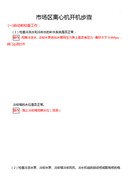
市场区离心机开机步骤(一)启动前检查工作:(1)检查冷冻水和冷却水的补水系统是否正常;观察冷冻水、冷却水泵进出水管网压力表上是否有压力,最好大于0.4Mpa,阀门必须打开冷却塔的水位是否正常。
(2)检查冷冻水泵、冷却水泵、冷却塔冷却风机、冷水机组的启动柜或配电柜的电压表,确认供电电源在正常范围内10KV(范围9000V---10KV)。
检查电动机启动柜(机头)检查冷冻泵、冷却泵、冷却塔动力柜、控制柜有无异常(3)检查冷水机组润滑油油位、油温是否正常;注:主机停止运作(超过一个小时)要关闭油泵两个阀门,来电要重新开启,长期不用也要开启。
主机有无泄漏现象或其他异常现象。
(4)确认需要开机的冷水机组号,并检查需要开机的冷水机组冷却水和冷冻水进出口阀门是否完全打开,其他不需要开启的冷水机组进出口阀门是否关闭。
open”(开启)状态,. 检查压力表数值是否有压力。
冷冻水阀门需要六角扳手(二)开机步骤:(1)前往“冷冻机房控制室”开启冷却水泵、冷冻水泵(一二级泵)、冷却塔组4台机组与4台冷却塔编号需一致,下步工作(2)前往“空调补水房”开启冷却塔补水一般情况下已经打自动,先打手动(确认可运行)→自动(3)检查“操作面板”冷却水循环、冷冻水循环等水循环操作完成约10分钟后,点击“输入/出”按钮,观察操作面板查看“冷冻水循环”、“冷却水循环”是否变为绿色,必须灯变绿,方可进行下一步操作!(4)检查“操作面板”上的“油槽温度”达到允许范围,才可下步操作操作:操作面板上的“油槽温度”42℃为宜,上下浮动5℃(即37℃~47℃之间).系统开关向上为开,向下为关操作:先开“系统开关”(活动臂旁,箱子外侧按钮),然后开箱内的“机组开关”,如只开一个压缩机,则只开一个“压缩机开关”(1#或2#)。
如要机组两个机头全部开启,则要将箱内三个开关全开。
注:操作面板如死机。
可拔掉插槽排线、电脑电源线。
重启即可(6)控制面板点击“自动”开启主机操作:等以上操作均正常了,点击“自动”开启主机(三)运行中记录(每两小时查看):(1)观察油泵:液位、是否有杂质(2)记录运行数据(三大项):冷凝器、蒸发器、供油系统点击“蒸发器”,记录右侧罗列数据在主界面,记录“供油系统”数据,包含吸气压力、排气压力。


麦克维尔磁悬浮离心特点麦克维尔磁悬浮离心是一种新型的离心机技术,它利用磁悬浮技术将转子悬浮在气膜中,从而实现了高速旋转。
与传统的离心机相比,麦克维尔磁悬浮离心具有以下特点:1. 高速旋转能力:麦克维尔磁悬浮离心的转子可以实现高速旋转,最高转速可达几万转每分钟。
这一特点使得磁悬浮离心在很多领域都有广泛的应用,如制药、生物技术、食品工业等。
高速旋转能力可以大大提高离心过程中的分离效率和产能。
2. 高精度悬浮控制:麦克维尔磁悬浮离心采用磁悬浮技术,通过磁力对转子进行悬浮控制。
这种控制方式可以实现非接触悬浮,并且对转子的悬浮位置进行高精度的控制。
通过精确的悬浮控制,可以有效地减少转子与离心机主体之间的摩擦,降低机械损耗,提高使用寿命。
3. 低振动、低噪音:由于麦克维尔磁悬浮离心的转子悬浮在气膜中,几乎没有与主体接触的部件,因此可以实现非常低的振动和噪音水平。
这对于精密实验和对样品要求比较高的应用非常重要,可以提高实验的可靠性和准确性。
4. 易于清洗和维护:麦克维尔磁悬浮离心的转子与主体之间没有接触,因此转子的清洗变得更加容易。
在传统离心机中,转子与主体接触的部件可能很难清洗,甚至需要经过拆卸才能进行清洗。
而磁悬浮离心的转子可以直接放入清洗液中,大大简化了清洗过程。
此外,磁悬浮离心的结构相对简单,维护成本也较低。
5. 多功能应用:麦克维尔磁悬浮离心具有很强的适应性和灵活性,可以用于多种不同的应用。
除了常见的离心分离外,磁悬浮离心还可以用于凝胶电泳、DNA 提取、核酸纯化等实验室分析和制备的过程中。
通过不同的转子和程序设置,可以实现不同样品的分离和处理,满足不同的实验需求。
总之,麦克维尔磁悬浮离心以其高速旋转能力、高精度悬浮控制、低振动低噪音、易洗涤维护和多功能应用等特点,在科学研究和工业生产中有着广泛的应用前景和价值。
随着科学技术的不断发展,磁悬浮离心将会进一步完善和应用,为相关领域的研究和生产带来更好的效果和效益。

机组参数品牌麦克维尔 McQuay ®产地 中国 武汉型式 水冷离心式冷水机组型号 WSC079LAR35F/E2609/C2209每台制冷量 冷吨300耗电指标kW/Ton 0.654输入功率 kW 196.1制冷剂类型HFC—134a 压缩机形式半封闭离心式单机压缩动力传送齿轮增速能量调节范围10%-100%无级调节驱动方式电机驱动防喘振散流滑块与前置导流叶片联动(无热气旁通)供油系统油泵类型齿轮式冷却方式水冷板式换热器油过滤器10μm 紧急润滑系统自动供油蒸发器式样/型号壳管满液式/E2609载冷剂水出口温度℃7进口温度℃12流量m3/h 181.8压降kPa 72.4水侧承压MPa 1.0进出水管公称直径mm DN200污垢系数m 2℃/kW 0.0176换热管壁厚mm 0.635流程数2换热管螺纹加强型铜管保温材料19mm聚乙烯板水接管形式右接冷凝器式样/形式壳管满液式/C2209进口温度℃32出口温度℃37流量m3/h 214.2压降kPa 38.4水侧承压MPa 1.0进出水管公称直径mm DN200污垢系数m 2℃/kW 0.044流程数2换热管材料螺纹加强型铜管换热管壁厚mm 0.635水接管形式右接电气启动形式星—三角配电电源380V/3Ph/50Hz 电机形式鼠笼引入式转速RPM 2980满载电流A 349启动电流A 846电机冷却方式冷媒冷却减震方式9mm避震橡胶减震垫外形尺寸长X宽X高mm 3360X1245X1971机组重量机组重量kg 4518运行重量kg 4987上表中的制冷量根据下述条件而定:冷冻水出水温度7℃;冷冻水进水温度12℃;冷却水进水温度32℃;冷却水出水温度37℃麦克维尔McQuay ®离心式冷水机组技术资料工程名称:设备名称:McQuay ®麦克维尔半封闭单级压缩离心式冷水机组高压保护器及微电脑感应微电脑控制及微电脑感应油压保护器及微电脑感应过载保护器及微电脑感应Surge Guard防喘振装置独有的后备供油系统电压感应保护微电脑控制微电脑控制水流压差控制器微电脑控制微电脑控制最高电量限流及过载保护微电脑控制最高电量限流及过载保护微电脑控制如有非标项目,请在会发生变动相应的选项后打"√",并将该项的参数更改为非标工况离心式冷水机组安全控制及保护措施麦克维尔McQuay ®单螺杆式冷水机组供货范围电气控制屏(马达启动器)电机过载保护电压过高/过低保护相序保护随机技术资料McQuay ®麦克维尔半封闭单级压缩离心式冷水机组MicroTech II 微电脑控制器蒸发器及低温部分原厂保温冷冻水出水温度控制橡胶减震垫冷冻及冷却水系统压差开关进口HFC—134a制冷剂及润滑油压缩机高压保护蒸发器低压保护油压过高/过低保户油泵过载保护重新循环启动超负荷控制压缩机排气温度过高保护水流循环系统联锁负荷过低(喘振状态)电源紧急中断。
麦克维尔空调离心机组开机实操手册1. 引言麦克维尔离心机组(以下简称机组)是一种高效、可靠、节能的制冷设备,广泛应用于大型商业建筑、高端酒店、医院、电信机房等场所中。
本文档旨在介绍该机组的开机实操手册,帮助使用者掌握正确的操作流程,确保机组能够正常运行。
2. 开机前的准备工作在启动机组之前,需要进行以下准备工作:2.1 装机确保机组已经完成了安装工作,包括:•圆形管道的安装和连接;•机组和周围环境之间的隔离;•冷凝水管道的布置;•排水系统的设置。
2.2 检查检查机组是否符合以下条件:•通风良好,有足够的空间;•电源充足,电线完整;•弹性支座按规定安装,地脚螺栓拧紧;•环境温度和湿度符合机组的技术要求;•冷却水管路和空气管路连接正确,散热排风良好。
3. 开机操作流程3.1 打开凸轮箱门机组开机前,应当打开凸轮箱门,观察凸轮、连杆、锻件、凸轮轴和连杆轴承等部件是否处于正常状态,无变形等问题。
3.2 启动水泵启动水泵前,先确保水泵联轴器处于分离状态,然后按照以下步骤启动水泵:1.将水泵手动开启电源;2.转动切换开关,将手动模式改为自动模式;3.按下启动按钮,水泵开始启动;4.等待水泵自动完成排气,并确保水泵进水管路畅通无阻。
3.3 开启机组在水泵正常工作后,可以开始启动机组了。
按照以下步骤操作:1.将机组控制器切换至“手动”模式;2.设置机组的开机参数,如供水温度、供水流量等;3.按下“启动”按钮,整机系统开始启动,主电机开始加速;4.观察凸轮箱中各部件的运转情况,确保机组运转平稳。
3.4 监测机组运行情况启动机组后,需要进行实时监测,确保机组运行正常。
常见的监测方法有:•温度监测:观察供水温度、回水温度等参数是否符合机组的技术要求;•压力监测:观察系统水泵的进出口压力,确保机组流量正常;•电气监测:观察机组的用电情况,确保电流稳定;•声音监测:观察机组的运行声音是否正常,无异常响声。
4. 停机操作流程当机组需要停机时,应当按照以下步骤进行停机操作:1.将机组控制器切换至“停机”模式;2.待主电机完全停止后,关闭水泵电源;3.关闭机组的排放阀门以及配气阀门;4.将机组装置加注抗冻液。
大冷吨冷水机组采用高压电机的科学及合理性离心制冷压缩机额定电压有380V,3KV,6KV,10KV。
采用高压供电对用户可节省投资30%~50%,还能减少维护费用。
大型离心制冷站宜采用高压启动,在机组启动时,启动电流小,对电网的冲击较小;在机组运行时,运行电流小,会节省一定的电能。
选用高压电机的配置方案,可以从整个机房配置、变配电设计及运行费用上,大大的提高建设方的经济效益。
高压电机适用范围。
根据中华人民共和国工业用电规程规定,在电机容量大于200KW 时,电力驱动设备宜选用高压电机。
我国电网标准供电为高压电,离心式冷水机组又适合采用高压电机,所以现在市场上采用高压电机冷水机组的用户已经越来越多。
直接采用高压电机可省去变压器等电器设备投资,减少变压器的运行损耗。
高压电机的启动电流远小于380V电机,可以采用直接启动,其变配电设备、备用发电机的容量可以远小于380V电机,大大减少用户综合投资,也大大减少有色金属材料的使用量。
高压机组与低压机组投资成本及综合性能分析表:综上所述,在电机容量大于200KW时,从冷机整体初投资的经济性、冷机长期运行电费的经济性以及其他供电和用电设备的可靠性来综合考虑,适宜采用高压电机冷水机组的方案,该方案充分考虑了系统的简便性、适应性及节能性各个方面,并有效解决冷水机组启动时对电网存在较大冲击的问题。
目前,国内采用高压机组的项目正呈直线上升趋势,曾得到用户一致好评的项目,主要有:保定英利、韩国SACI SAMSUNG、红沿河核电站、宁德核电站、阳江核电站、大連热电厂、富士康、北汽富田、长城汽车、东风日产汽车等上百家企业用户。
其中富士康集团采购项目亦再次向麦克维尔公司征询高压系统方案。
高压电机冷水机组适宜场合的应用优势之多,代表了较大冷量冷水机组的发展方向,已经成为越来越多客户的首选方案。
高压启动与与低压启动机组的优缺点比较:1、高压启动相对于低压启动的冷水机组相比,机组本身投资将要略大;2、如果计算上相关的变压器(可取消)、电缆(变细了)、桥架(电缆变轻了)、配电室中相关设备(变配电柜不要了)和节约的机房面积,高压启动将占优势;3、高压供电电流小,电路损失小,另外没有变压器,避免了变压器的铜损和和铁损,节省运行费用,而且电流小,运行更安全;4、380V系统需要一个变压器,对电网而言,变压器要吃掉电网的部分无功功率,供电局收费是按10AKV侧的功率因素收费,所以用380V时将要增加许多的功率因素补偿设备投资;5、节约机房面积;6、由于高压启动机组系统大大简化,使安装费用大大降低;7、高压电机效率高,技术成熟,操作简单;。