福禄克型万用表使用说明
- 格式:docx
- 大小:19.03 MB
- 文档页数:7

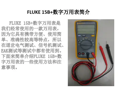
福禄克15B万用表使用说明福禄克15B数字万用表使用方法简介:福禄克15 B数字万用表属于比较简单的测量仪器。
本篇,教大家数字万用表的正确使用方法。
从数字万用表的电压、电阻、电流、二极管、三极管、MOS场效应管的测量等测量方法开始,让你更好的掌握万用表测量方法。
一、电压的测量1、直流电压的测量,如电池、随身听电源等。
首先将黑表笔插进“com”孔,红表笔插进“V Ω► ( 把旋钮选到此位置如图:直流选择档位(注意:“V-”表示直流电压档,“V~”表示交流电压档,“A”是电流档),接着把表笔接电源或电池两端;保持接触稳定。
数值可以直接从显示屏上读取,若显示为“OL”,则表明量程太小,那么就要加大量程后再测量工业电器。
如果在数值左边出现“-”,则表明表笔极性与实际电源极性相反,此时红表笔接的是负极。
2、交流电压的测量:交流选择档位表笔插孔与直流电压的测量一样,不过应该将旋钮打到交流档“V~”处所需的量程即可。
交流电压无正负之分,测量方法跟前面相同。
无论测交流还是直流电压,都要注意人身安全,不要随便用手触摸表笔的金属部分。
二、电流的测量电流选择档位按此键转换交流直1、直流电流的测量。
先将黑表笔插入“COM”孔。
若测量大于400mA的电流,则要将红表笔插入“10A”插孔并将旋钮打到直流“10A”档;若测量小于400mA的电流,则将红表笔插入“400mA”插孔,将旋钮打到直流400mA以内的合适量程。
调整好后,就可以测量了。
将万用表串进电路中,保持稳定,即可读数。
若显示为“OL.”,那么就要加大量程;如果在数值左边出现“-”,则表明电流从黑表笔流进万用表。
交流电流的测量。
测量方法与1相同,不过应选择交流模式,电流测量完毕后应将红笔插回“”孔,若忘记这一步而直接测电压,哈哈!你的表或电源会在“一缕青烟中上云霄”--报废!三、电阻的测量:按此键转换二极将表笔插进“COM”和”孔中,把旋钮打旋到“Ω”中所需的量程,用表笔接在电阻两端金属部位,测量中可以用手接触电阻,但不要把手同时接触电阻两端,这样会影响测量精确度的--人体是电阻很大但是有限大的导体。
287/289 True-rms Digital Multimeters安全须知访问以注册您的产品并获取更多信息。
警告表示可能对用户造成危险的状况和操作。
XW警告为了防止可能发生的触电、火灾或人身伤害:•使用仪表前请先阅读“安全须知”。
•必须按照本手册的规定使用仪表,否则仪表提供的保护措施可能会失效。
•切勿使用已损坏的仪表。
使用仪表之前,请检查仪表的外壳,检查是否存在裂纹或塑胶缺损。
特别注意接头周围的绝缘。
•使用仪表之前,请确定电池盖已经闭合并且扣紧。
•打开电池盖之前,请先取下仪表上的测试导线。
•检查测试导线的绝缘是否损坏或导线金属是否裸露在外。
检查测试导线是否导通。
若导线有损坏,请更换以后再使用仪表。
•在端子间或任何一个端子与接地点之间施加的电压不能超过仪表上标示的额定值。
•在外盖取下或机壳打开时,请勿使用仪表。
•对 30 V 交流(有效值)、42 V 交流(峰值)或 60 V直流以上的电压,应格外小心。
这些电压有电击危险。
•必须使用本手册指定的替换保险丝。
•测量时,必须使用正确的端子、功能档和量程档。
•不要单独工作。
•测量电流时,应先切断电路的电源,再把仪表连接到电路上。
记住:仪表必须和电路串联。
•在进行电气连接时,先连接公用测试导线,然后再连接带电测试导线;拆线时,先拆除带电测试导线,然后再拆除公用测试导线。
•若仪表工作失常,请勿使用。
产品的保护功能可能受损。
若有疑问,应将仪表送修。
PN 4271782 (Simplified Chinese)August 2012 Rev. 1, 1/18© 2012-2018 Fluke Corporation. All rights reserved.All product names are trademarks of their respective companies. Specifications are subject to change without notice.•切勿在有爆炸性的气体、蒸汽或灰尘附近使用仪表。

Models 175, 177 & 179True RMS MultimetersMay 2003 Rev. 1, 10/08© 2003-2008 Fluke Corporation. All rights reserved. Printed in USA.Specifications are subject to change without notice.All product names are trademarks of their respective companies.Lifetime Limited WarrantyEach Fluke 20, 70, 80, 170 and 180 Series DMM will be free from defects in material and workmanship for its lifetime. As used herein, “life-time” is defined as seven years after Fluke discontinues manufacturing the product, but the warranty period shall be at least ten years from the date of purchase. This warranty does not cover fuses, disposable batteries, damage from neglect, misuse, contamination, alteration,accident or abnormal conditions of operation or handling, including failures caused by use outside of the product’s specifications, or normalwear and tear of mechanical components. This warranty covers the original purchaser only and is not transferable.For ten years from the date of purchase, this warranty also covers the LCD. Thereafter, for the lifetime of the DMM, Fluke will replace theLCD for a fee based on then current component acquisition costs.To establish original ownership and prove date of purchase, please complete and return the registration card accompanying the product, or register your product on . Fluke will, at its option, repair at no charge, replace or refund the purchase price of a defective product purchased through a Fluke authorized sales outlet and at the applicable international price. Fluke reserves the right to charge for importation costs of repair/replacement parts if the product purchased in one country is sent for repair elsewhere.If the product is defective, contact your nearest Fluke authorized service center to obtain return authorization information, then send theproduct to that service center, with a description of the difficulty, postage and insurance prepaid (FOB Destination). Fluke assumes no riskfor damage in transit. Fluke will pay return transportation for product repaired or replaced in-warranty. Before making any non-warranty re-pair, Fluke will estimate cost and obtain authorization, then invoice you for repair and return transportation.THIS WARRANTY IS YOUR ONLY REMEDY. NO OTHER WARRANTIES, SUCH AS FITNESS FOR A PARTICULAR PURPOSE, AREEXPRESSED OR IMPLIED. FLUKE SHALL NOT BE LIABLE FOR ANY SPECIAL, INDIRECT, INCIDENTAL OR CONSEQUENTIAL DAM-AGES OR LOSSES, INCLUDING LOSS OF DATA, ARISING FROM ANY CAUSE OR THEORY. AUTHORIZED RESELLERS ARE NOT AUTHORIZED TO EXTEND ANY DIFFERENT WARRANTY ON FLUKE’S BEHALF. Since some states do not allow the exclusion or limita-tion of an implied warranty or of incidental or consequential damages, this limitation of liability may not apply to you. If any provision of this warranty is held invalid or unenforceable by a court or other decision-maker of competent jurisdiction, such holding will not affect the validity or enforceability of any other provision.Fluke Corporation Fluke Europe B.V.P.O. Box 9090 P.O. Box 1186Everett, WA 98206-9090 5602 BD EindhovenNetherlandsU.S.A. TheVisit the Fluke website at: Register your Meter at: 2/02Table of ContentsPage TitleContacting Fluke (1)"Warning" and "Caution" Statements (1)Unsafe Voltage (1)Test Lead Alert (1)Battery Saver ("Sleep Mode") (2)Terminals (2)Rotary Switch Positions (2)Display (3)MIN MAX AVG Recording Mode (4)Display HOLD and AutoHOLD Modes (4)YELLOW Button (4)Display Backlight (Model 177 and 179 Only) (4)Manual Ranging and Autoranging (5)Power-Up Options (5)Making Basic Measurements (6)Measuring AC and DC Voltage (6)Measuring Resistance (6)Measuring Capacitance (6)Testing for Continuity (7)Measuring Temperature (Model 179 Only) (7)Testing Diodes (7)Measuring AC or DC Current (8)Understanding AC Zero Input Behavior of True RMS Meters (8)Measuring Frequency (9)Using the Bar Graph (9)Cleaning (10)Testing the Fuses (10)Replacing the Battery and Fuses (10)Specifications (11)iXW Warning. Read before using the Meter:To avoid possible electrical shock or personal injury, follow these guidelines:⇒Use the Meter only as specified in this manual or the protection provided by the Meter might be impaired.⇒Do not use the Meter or test leads if they appear damaged, or if the Meter is not operating properly. If in doubt, have the Meter serviced.⇒Always use the proper terminals, switch position, and range for measurements.⇒Verify the Meter's operation by measuring a known voltage.⇒Do not apply more than the rated voltage, as marked on the Meter, between the terminals or between any terminal and earth ground.⇒Use caution with voltages above 30 V ac rms, 42 V ac peak, or 60 V dc. These voltages pose a shock hazard.⇒Replace the battery as soon as the low battery indicator ( b ) appears.⇒Disconnect circuit power and discharge all high-voltage capacitors before testing resistance, continuity, diodes, or capacitance.⇒Do not use the Meter around explosive gas or vapor.⇒When using the test leads, keep your fingers behind the finger guards.⇒Remove test leads from the Meter before opening the Meter case or battery door.SymbolsB AC (Alternating Current) I FuseF DC (Direct Current) P Conforms to European Union directivesFDC/AC $Canadian Standards Association BJ Earth ground T Double insulatedW Important Information; see manual ! Underwriters Laboratories, Inc.Meter in accordance with IEC 61010-1. 54CJ;Conforms to relevant Australian standardsb Battery (Low battery when shown ondisplay.)#VDE (Verband Deutscher Electroniker)s Inspected and licensed by TÜV(Technischer Überwachungs Verein)Product ServicesiiModels 175, 177 & 179True RMS MultimetersThe Fluke Model 175, Model 177, and Model 179 are battery-powered, true-RMS multimeters (hereafter "the Meter") with a 6000-count, 3 3/4-digit display and a bar graph. This manual applies to all three models. All figures show the Model 179. These meters meet CAT III and CAT IV IEC 61010 standards. The IEC 61010 safety standard defines four overvoltage categories (CAT I to IV) based on the magnitude of danger from transient impulses. CAT III meters are designed to protect against transients in fixed-equipment installations at the distribution level; CAT IV meters are designed to protect against transients from the primary supply level (overhead or underground utility service). The Meter measures or tests the following:♦AC / DC voltage & current ♦ Diodes♦ Resistance ♦ Continuity♦Voltage & current frequency ♦ Capacitance♦Temperature (Model 179 only)Contacting FlukeTo contact Fluke, call:1-888-993-5853 in USA1-800-363-5853 in Canada+31 402-678-200 in Europe+81-3-3434-0181 in Japan+65-738-5655 in Singapore+1-425-446-5500 from anywhere in the worldVisit Fluke's web site at .Register your Meter at . "Warning" and "Caution" StatementsA "XW Warning" identifies hazardous conditions and actions that could cause bodily harm or death.A "Caution" identifies conditions and actions that could damage the Meter, the equipment under test, or cause permanent loss of data.Unsafe VoltageTo alert you to the presence of a potentially hazardous voltage, when the Meter detects a voltage ≥30 V or a voltage overload (OL), the Y symbol is displayed.Test Lead AlertTo remind you to check that the test leads are in the correct terminals, LEAd is momentarily displayed when you move the rotary switch to or from the mA or A position.XW WarningAttempting to make a measurement with a test lead inan incorrect terminal might blow a fuse, damage theMeter, and cause serious personal injury.1Models 175, 177 & 179 Users Manual2Battery Saver ("Sleep Mode")The Meter enters the "Sleep mode" and blanks the display if there is no function change or button press for 20 minutes. To disable the Sleep mode, hold down the YELLOW button while turning the Meter on. The Sleep mode is always disabled in the MIN MAX AVG mode and the AutoHOLD mode.TerminalsRotary Switch PositionsSwitch PositionMeasurement FunctionK Hz AC voltage from 30.0 mV to 1000 V. Frequency from 2 Hz to 99.99 kHz. L Hz DC voltage 1 mV to 1000 V.Frequency from 2 Hz to 99.99 kHz. m LTDC mV 0.1 mV to 600 mV. Temperature − 40 °C to + 400 °C− 40 °F to + 752 °Fe E Ohms from 0.1 Ω to 50 M Ω. Farads from 1 nF to 9999 μF.R G Beeper turns on at <25 Ω and turns off at >250 Ω. Diode test. Displays OL above 2.4 V. F B mA AC mA from 3.00 mA to 400 mA DC mA from 0.01 mA to 400 mA Hz Frequency of AC mA 2 Hz to 30 kHz. F AC A from 0.300 A to 10 A B A DC A from 0.001 A to 10 A >10.00 display flashes. >20 A, OL is displayed.HzFrequency of AC A 2 Hz to 30 kHz.Note: AC voltage and current AC-coupled, true RMS, up to 1 kHz.True RMS MultimetersDisplay3DisplayNo. SymbolMeaning7 n μ F, °F, °C mVA, Mk e , kHz Measurement units.8 DC, ACDirect current, alternating current. 9 bLow battery. Replace battery. 10 610000mV All possible ranges. 11 Bar graph Analog display.12Auto Range The Meter selects the range with the best resolution.Manual RangeThe user selects the range. 13 ±Bar graph polarity. 14 0L The input out of range.15 LEAdW Test lead alert. Displayed when the rotary switch is moved to or from the mA or A position.Error MessagesbAtt Replace the battery immediately.diSC In the capacitance function, too much electrical charge is present on the capacitor being tested. EEPr Err Invalid EEPROM data. Have Meter serviced. CAL Err Invalid calibration data. Calibrate Meter. OPEnOpen thermocouple is detected.Models 175, 177 & 179 Users Manual4MIN MAX AVG Recording ModeThe MIN MAX AVG recording mode captures the minimum and maximum input values, and calculates a running average of all readings. When a new high or low is detected, the Meter beeps.NoteFor DC functions, accuracy is the specified accuracy of the measurement function ± 12 counts for changes longer than 350 ms in duration.For AC functions, accuracy is the specified accuracy of the measurement function ± 40 counts for changes longer than 900 ms in duration.To use MIN MAX AVG recording:⇒ Make sure that the Meter is in the desired measurementfunction and range. (Autoranging is disabled in the MIN MAX AVG mode.) ⇒ Press MIN MAX to activate MIN MAX AVG mode.and MAX light, and the highest reading detected since entering MIN MAX AVG is displayed. ⇒ Press MIN MAX to step through the low (MIN ), average(AVG ), and present readings.⇒ To pause MIN MAX AVG recording without erasing storedvalues, press HOLD . h is displayed.To resume MIN MAX AVG recording, press HOLD again. h turns off.⇒ To exit and erase stored readings, press MIN MAX for 1second or turn the rotary switch.Display HOLD and AutoHOLD ModesXW WarningTo avoid electric shock, do not use the Display HOLD or AutoHOLD mode to determine if a circuit is live. Unstable or noisy readings will not be captured.In the Display HOLD mode, the Meter holds the reading on the display.In the AutoHOLD mode, the Meter holds the reading on the display until it detects a new stable reading. Then the Meter beeps and displays the new reading. ⇒ Press HOLD to activate Display HOLD. h lights. ⇒ Press HOLD again to activate AutoHOLD. A h lights. ⇒ Press HOLD again to resume normal operation.To resume normal operation at any time, press HOLD for 1 second or turn the rotary switch.YELLOW ButtonPress the YELLOW button to select alternate measurementfunctions on a rotary switch setting, e.g., to select DC mA, DC A, Hz, temperature (Model 179 only), capacitance, diode test.Display Backlight (Model 177 and 179 Only)Press S to toggle the backlight on and off. The backlight automatically turns off after 2 minutes.True RMS MultimetersManual Ranging and Autoranging5Manual Ranging and AutorangingThe Meter has both Manual range and Autorange modes.⇒ In the Autorange mode, the Meter selects the range with thebest resolution.⇒ In the Manual Range mode, you override Autorange and selectthe range yourself.When you turn the Meter on, it defaults to Autorange and Auto Range is displayed.1. To enter the Manual Range mode, press RANGE .Manual Range is displayed.2. In the Manual Range mode, press RANGE to increment therange. After the highest range, the Meter wraps to the lowest range.NoteYou cannot manually change the range in the MIN MAX AVG, or Display HOLD modes.If you press RANGE while in MIN MAX AVG, or Display HOLD, the Meter beeps twice, indicating an invalid operation, and the range does not change.3. To exit Manual Range, press RANGE for 1 second or turn therotary switch.The Meter returns to Autorange and Auto Range is displayed.Power-Up OptionsTo select a Power-Up Option, hold down the button indicated while turning the Meter from OFF to any switch position.Power-Up Options are cancelled when the Meter is turned OFF.Button Power-Up Options AutoHOLDH K switch position turns on all LCD segments. L switch position displays the software versionnumber.m L switch position displays the model number. M Disables beeper. (bEEP ) R Enables "Smoothing" mode. (S---)Dampens display fluctuations of rapidly changing inputs by digital filtering.B(YELLOW)Disables automatic power-down ("Sleep mode"). (PoFF )Sleep mode is also disabled while the Meter is in a MIN MAX AVG Recording mode, or the AutoHOLD mode.SDisables automatic 2-minute backlight timeout. (LoFF ) (Model 177 and 179 Only )Models 175, 177 & 179 Users Manual6Making Basic MeasurementsThe figures on the following pages show how to make basic measurements.When connecting the test leads to the circuit or device, connect the common (COM ) test lead before connecting the live lead; when removing the test leads, remove the live lead before removing the common test lead.XW WarningTo avoid electric shock, injury, or damage to the Meter, disconnect circuit power and discharge all high-voltage capacitors before testing resistance, continuity, diodes, or capacitance.Measuring AC and DC VoltageVolts ACVolts DCAIK03F.EPSMeasuring ResistanceAIK04F.EPSMeasuring CapacitanceAIK05F.EPSMaking Basic MeasurementsTesting for ContinuityAIK06F.EPS Measuring Temperature (Model 179 Only)AIK10F.EPS X W Warning: Do not connect 80BK-A to live circuits. Testing DiodesOpenAIK07F.EPSUsers ManualMeasuring AC or DC CurrentXW WarningTo avoid personal injury or damage to the Meter: • Never attempt to make an in-circuit currentmeasurement when the open-circuit potential to earth is >1000 V.• Check the Meter's fuses before testing. (See “Testing the Fuses”.)• Use the proper terminals, switch position, and range for your measurement.• Never place the probes in parallel with a circuit or component when the leads are plugged into the current terminals.Turn power OFF, break circuit, insert Meter in series, turn power on.Understanding AC Zero Input Behavior of True RMS Meters Unlike averaging meters, which can accurately measure only pure sinewaves, True RMS meters accurately measure distorted waveforms. Calculating True RMS converters require a certain level of input voltage to make a measurement. This is why AC voltage and current ranges are specified from 5% of range to100% of range. Non-zero digits that are displayed on a True RMS meter when the test leads are open or are shorted are normal. They do not affect the specified AC accuracy above 5% of range. Unspecified input levels on the lowest ranges are: • AC voltage: below 5% of 600 mV AC, or 30 mV AC • AC current: below 5% of 60 mA AC, or 3 mA ACUsing the Bar GraphMeasuring FrequencyXW WarningTo avoid electrical shock, disregard the bar graph for frequencies > 1 kHz. If the frequency of the measured signal is > 1 kHz, the bar graph is unspecified.The Meter measures the frequency of a signal. The trigger level is 0 V, 0 A AC for all ranges.AC/DC Voltage FrequencyAC Current FrequencyAIK09F.EPS⇒ To exit frequency, press YELLOW button or turn the rotaryswitch.⇒ In frequency, the bar graph shows the AC/DC voltage or ACcurrent accurately up to 1 kHz.⇒ Select progressively lower ranges using manual ranging for astable reading.Using the Bar GraphThe bar graph is like the needle on an analog Meter. It has anoverload indicator (>) to the right and a polarity indicator (±) to the left.Because the bar graph updates about 40 times per second, which is 10 times faster than the digital display, the bar graph is useful for making peak and null adjustments and for observing rapidly changing inputs.The bar graph is disabled when measuring capacitance ortemperature. In frequency, the bar graph accurately indicates the voltage or current up to 1 kHz.The number of lit segments indicates the measured value and is relative to the full-scale value of the selected range .In the 60 V range, for example (see below), the major divisions on the scale represent 0, 15, 30, 45, and 60 V. An input of −30 V lights the negative sign and the segments up to the middle of the scale.AIK11F.EPSUsers ManualCleaningWipe the case with a damp cloth and mild detergent. Do not use abrasives or solvents. Dirt or moisture in the terminals can affect readings.Testing the FusesXW WarningTo avoid electrical shock or injury, remove the test leads and any input signals before replacing the fuse.Test fuses as shown below.AIK12F.EPS Replacing the Battery and FusesXW WarningTo avoid shock, injury, or damage to the Meter: •Use ONLY fuses with the amperage, interrupt,voltage, and speed ratings specified.•Replace the battery as soon as the low battery indicator (b) appears.SpecificationsSpecificationsAccuracy is specified for 1 yr after calibration, at operating temperatures of 18 °C to 28 °C, with relative humidity at 0 % to 90 %. Accuracy specifications take the form of: ± ( [ % of Reading ] + [ Counts ] )Maximum voltage between any terminal and earth ground: 1000 V DC or AC RMSSurge Protection: 8 kV peak per IEC 61010W Fuse for mA inputs: W Fuse for A input: 440 mA, 1000 V FAST Fuse 11 A, 1000 V FAST FuseDisplay: Digital: 6000 counts, updates 4/secBar Graph: 33 segments;Updates40/secFrequency: 10,000countsCapacitance: 1,000 countsAltitude: Operating: 2000 m; Storage: 12,000 mTemperature: Operating: −10 °C to +50 °C;Storage: −40 °C to +60 °CTemperature coefficient: 0.1 X (specified accuracy / °C(< 18 °C or > 28 °C)ElectromagneticCompatibility(EN 61326-1:1997):In an RF field of 3 V/M, accuracy = specified accuracy except in temperature: specified accuracy ± 5 °C (9 °F) Relative Humidity: MaximumNoncondensing90 % to 35 °C75 % to 40 °C45 % to 50 °CBattery Life: Alkaline: 400 hrs typicalSize (H x W x L): 4.3 cm x 9 cm x 18.5 cmWeight: 420 gSafety Compliances: ANSI/ISA S82.02.01, CSA C22.2-1010.1, IEC 61010 to 1000 V Measurement Category III, 600 V Measurement Category IVCertifications: CSA, TÜV (EN61010), UL, P, ;, VDEUsers ManualAccuracy ±( [ % of Reading ] + [ Counts ] ) Function Range 1 ResolutionModel 175 Model 177 Model 179AC Volts 2, 3600.0 mV6.000 V60.00 V600.0 V1000 V 0.1 mV0.001 V0.01 V0.1 V1 V1.0 % + 3(45 Hz to 500 Hz)2.0 % + 3 (500 Hz to 1 kHz)1.0 % + 3(45 Hz to 500 Hz)2.0 % + 3 (500 Hz to 1 kHz)1.0 % + 3(45 Hz to 500 Hz)2.0 % + 3 (500 Hz to 1 kHz)DC mV 600.0 mV 0.1 mV 0.15 % + 2 0.09 % + 2 0.09 % + 2DC Volts 6.000 V60.00 V600.0 V 0.001 V0.01 V0.1 V0.15 % + 2 0.09 % + 2 0.09 % + 21000 V 1 V 0.15 % + 2 0.15 % + 2 0.15 % + 2Continuity 600Ω 1ΩMeter beeps at < 25 Ω, beeper turns off at > 250 Ω; detects opens or shorts of 250 μs orlonger.Ohms 600.0 Ω6.000 kΩ60.00 kΩ600.0 kΩ6.000 MΩ50.00 MΩ0.1 Ω0.001 kΩ0.01 kΩ0.1 kΩ0.001 MΩ0.01 MΩ0.9 % + 20.9 % + 10.9 % + 10.9 % + 10.9 % + 11.5 % + 30.9 % + 20.9 % + 10.9 % + 10.9 % + 10.9 % + 11.5 % + 30.9 % + 20.9 % + 10.9 % + 10.9 % + 10.9 % + 11.5 % + 3Diode test 2.400 V 0.001 V 1 % + 2Capacitance 1000 nF10.00 μF100.0 μF9999 μF 4 1 nF0.01 μF0.1 μF1 μF1.2 % + 21.2 % + 21.2 % + 210 % typical1.2 % + 21.2 % + 21.2 % + 210 % typical1.2 % + 21.2 % + 21.2 % + 210 % typicalAC Amps 5 (True RMS) (45 Hz to 1 kHz) 60.00 mA400.0 mA66.000 A10.00 A70.01 mA0.1 mA0.001 A0.01 A1.5 % + 3 1.5 % + 3 1.5 % + 31. All AC voltage and AC current ranges are specified from 5 % of range to 100 % of range.2. Crest factor of ≤ 3 at full scale up to 500 V, decreasing linearly to crest factor ≤ 1.5 at 1000 V.3. For non-sinusoidal waveforms, add -(2% reading + 2% full scale) typical, for crest factors up to 3.4. In the 9999 μF range for measurements to 1000 μF, the measurement accuracy is 1.2 % + 2 for all models.5. Amps input burden voltage (typical): 400 mA input 2 mV/mA, 10 A input 37 mV/A.6. 400.0 mA accuracy specified up to 600 mA overload.7. > 10A unspecified.SpecificationsAccuracy ±( [ % of Reading ] + [ Counts ] )Function Range 1 ResolutionModel 175 Model 177 Model 179DC Amps460.00 mA400.0 mA66.000 A10.00 A70.01 mA0.1 mA0.001 A0.01 A1.0 % + 3 1.0 % + 3 1.0 % + 3Hz(AC- or DC- coupled, V or A 2, 3 input ) 99.99 Hz999.9 Hz9.999 kHz99.99 kHz0.01 Hz0.1 Hz0.001 kHz0.01 kHz0.1 % + 1 0.1 % + 1 0.1 % + 1Temperature -40 °C to +400 °C-40 °F to +752 °F 0.1 °C0.1 °FNA NA1 % + 1051 % + 185MIN MAX AVG For DC functions, accuracy is the specified accuracy of the measurement function ±12 counts for changes longer than 350 ms in duration.For AC functions, accuracy is the specified accuracy of the measurement function ±40 counts for changes longer than 900 ms induration.1. All AC voltage and AC current ranges are specified from 5 % of range to 100 % of range.2. Frequency is specified from 2 Hz to 99.99 kHz in Volts and from 2 Hz to 30 kHz in Amps.3. Below 2 Hz, the display shows zero Hz.4. Amps input burden voltage (typical): 400 mA input 2 mV/A, 10 A input 37 mV/A.5. Does not include error of the thermocouple probe.6. 400.0 mA accuracy specified up to 600 mA overload.7. > 10A unspecified.Users ManualFunction Overload Protection1Input Impedance(Nominal)Common Mode Rejection Ratio(1 k Ω Unbalanced) Normal Mode RejectionVolts AC 1000 V RMS > 10 M Ω < 100 pF > 60 dB @ DC, 50 Hz or 60 HzVolts DC 1000 V RMS > 10 M Ω < 100 pF >120 dB @ DC, 50 Hz or 60 Hz > 60 dB @ 50 Hz or 60 Hz mV/T1000 V RMS 2> 10 M Ω < 100 pF >120 dB @ DC, 50 Hz or 60 Hz > 60 dB @ 50 Hz or 60 Hz Full Scale Voltage To:Open Circuit TestVoltage600 k Ω 50 M Ω Short Circuit CurrentOhms/Capacitance 1000 V RMS 2 < 8.0 V DC < 660 mV DC< 4.6 V DC< 1.1 mA Continuity/Diodetest1000 V RMS 2< 8.0 V DC2.4 V DC< 1.1 mA1. 10 7 V-Hz maximum.2.For circuits < 0.3 A short circuit. 660 V for high energy circuits.Function Overload Protection OverloadmA Fused, 44/100 A, 1000 V FAST Fuse 600 mA overload for 2 minutes maximum, 10minutes rest minimumAFused, 11 A, 1000 V FAST Fuse20 A overload for 30 seconds maximum, 10 minutes rest minimum。
PN 4372130February 2014 (Simplified Chinese)© 2014 Fluke Corporation. All rights reserved. Specifications are subject to change without notice. All product names are trademarks of their respective companies.15B+/17B+/18B+Digital Multimeters有限保修及责权范围本产品自购买之日起,将可享受一年材料上及工艺上的质保,但此保修不包括保险丝(熔断)、一次性电池(用完)、或者由于意外事故、疏忽、滥用、改造、污染、及操作环境的反常而形成的损害。
零售商没有被授权代表 Fluke 扩充该保修的内容。
质保期间,如需服务,您可联系最近的 Fluke维修中心,获得认可信息,然后将产品送至该中心,并附上故障说明。
该保是您可获取补偿的唯一保修。
除此之外,没有为特别的目的而制定的保修,对于任何特殊的、间接的、偶然的、并发性的损害或各种损耗,Fluke概不负责。
因为有国家不允许对暗示保修或偶然的、并发性的损坏的排除或限制,上述责任限制也许不适用于您。
Fluke CorporationP.O. Box 9090 Everett, WA 98206-9090 U.S.A. Fluke Europe B.V. P.O. Box 1186 5602 BD Eindhoven The Netherlands11/99Service Centers:Fluke Beijing Service Center Room 401 SCITEC Tower Jianguomenwai Dajie Beijing 100004, PRCTel: 400-810-3435 Shanghai Shilu Instrument Co., Ltd.#139, Lane 2638, Hongmei Road (South) Shanghai 201108Standard Number: Q/SXAV 1-2002目录标题页码概述 (1)如何联系 Fluke (1)安全须知 (2)仪器概述 (5)接线端 (5)显示屏 (6)自动关机 (7)背照灯自动关闭 (7)测量 (7)手动及自动量程选择 (7)数据保持 (8)相对测量(仅限 17B+) (8)最小值/最大值模式(仅限 17B+) (8)测量交流电压和直流电压 (9)测量交流或直流电流 (10)i15B+/17B+/18B+用户手册测量电阻 (11)通断性测试 (11)测试二极管 (12)测量电容 (12)测量温度(仅限 17B+) (12)测量频率和占空比(仅限 17B+/18B+) (13)测试 LED(仅限 18B+) (13)维护 (14)一般维护 (15)测试保险丝 (15)更换电池和保险丝 (16)维修和零件 (17)通用技术指标 (18)准确度指标 (19)交流和直流电压 (19)交流和直流电流 (20)二极管测试、温度、电阻、电容、频率和占空比 (21)LED 测试和通断性阈值 (23)输入特性 (23)ii概述Fluke 15B+/17B+/18B+ Multimeters(以下称本产品)是4000 计数仪器。
fluke万用表运用阐明书中FLUKE15B型和FLUKE17B可以丈量电压、电阻、电流、二极管、三极管、MOS场效应管的丈量等几大功用归纳在一同的健旺的一款小仪器。
为了让你十分好的把握万用表丈量办法,电工之家来详解一下它的运用办法和功用与留心事项。
一、丈量电压时丈量直流电压时,如电池、随身听电源等。
首要将黑表笔插进相印的孔,把旋钮选到相印方位。
二、丈量沟通电压的时表笔插孔与直流电压的丈量相同,不过应当将旋钮打到沟通档场合需的量程即可。
沟通电压无正负之分,丈量办法跟前面相同。
不论测沟通仍是直流电压,要留心本身安全,不要随意用手触摸表笔的金属有些。
三、丈量电流时丈量直流电流时。
将黑表笔刺进对应孔。
将FLUKE15B型和FLUKE17B万用表串进电路中,坚持安稳,即可读数。
四、丈量电阻时用表笔接在电阻两头金属部位,丈量中可以用手触摸电阻,但不要把手一同触摸电阻两头,这么会影响丈量精确度,因为人体是电阻很大。
五、丈量二极管时表笔方位与电压丈量相同;用红表笔接二极管的正极,黑表笔接负极,这时会闪现二极管OL。
再次对调表笔会闪现一个数值。
再次沟通表笔,闪现屏闪现OL.则为正常。
因为二极管的反向电阻很大,不然此管已被击穿或功用现已改动。
六、三极管的丈量表笔插位同上;其原理同二极管。
先假定A脚为基极,用黑表笔与该脚相接,红表笔与别的两脚别离触摸别的两脚;然后再用红笔接A脚,黑笔触摸别的两脚,且此管为PNP管。
那么集电极和发射极怎样差异呢?数字表不能像指针表那样运用指针摆幅来差异。
七、MOS场效应管的丈量运用FLUKE15B型和FLUKE17B的二极管档。
若某脚与别的两脚间的正反压降均大于2V,即闪现1,此脚即为栅极G。
再沟通表笔丈量别的两脚,压降小的那次中,黑表笔接的是D极(漏极),红表笔接的是S极(源极)。
在运用FLUKE15B型和FLUKE17B的一同也要留心以下疑问防止或许遭到电击或人员危害,以及防止对电表或待测设备构成危害,请遵循下面的常规阐明运用电表:①进行联接时,先联接公共查验导线,再联接带电的查验导线;堵截联接时,则先断开带电的查验导线,再断开公共查验导线。
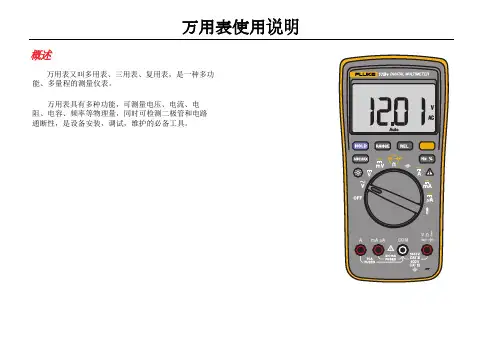
万用表使用说明概述万用表又叫多用表、三用表、复用表,是一种多功能、多量程的测量仪表。
万用表具有多种功能,可测量电压、电流、电阻、电容、频率等物理量,同时可检测二极管和电路通断性,是设备安装,调试,维护的必备工具。
安全须知警告表示可能对用户造成危险的状况和操作。
小心表示会对产品或受测设备造成损坏的状况和操作。
有关本产品和本手册所用的国际电气符号,请参阅表 1 中的解释。
阅读安全须知,并遵守安全工作规范。
警告为了防止可能发生的触电、火灾或人身伤害:•仔细阅读所有说明。
•在使用产品前,请先阅读所有安全须知。
•请仅将产品用于指定用途,否则可能减弱产品提供的防护。
•请勿在爆炸性气体、蒸汽周围或在潮湿环境中使用产品。
•使用产品前先检查外壳。
检查是否存在裂纹或塑胶件缺损。
请仔细检查端子附近的绝缘体。
•若产品损坏,请勿使用。
•若产品工作异常,请勿使用。
•遵守当地和国家的安全规范。
穿戴个人防护用品(经认可的橡胶手套、面具和阻燃衣物等),以防危险带电导体外露时遭受电击和电弧而受伤。
•仅使用正确的测量标准类别 (CAT)、电压和电流额定探头、测试导线和适配器进行测量。
•切勿在未安装探头保护帽的情况下在 CAT III 环境中使用测试探头。
保护帽可以将外露的探头金属部分降低至 4 毫米以下。
这样就减少了因短路产生弧闪的可能性。
•先测量一个已知电压,确定产品是否正常运行。
•请按照指定的测量类别、电压或电流额定值进行操作。
•端子间或每个端子与接地点之间施加的电压不能超过额定值。
Digital Multimeters安全须知•禁止触摸电压超过 30 V 真有效值交流电、42 V 交流电峰值或 60 V 直流电的带电导体。
•请勿使用已损坏的测试导线。
检查测试导线是否绝缘不良,并测量已知的电压。
•测量时,请先连接零线或地线,再连接火线;断开时,请先切断火线,再断开零线和地线。
•请将手指握在探针护指装置的后面。
•打开电池盖之前,首先断开所有探头、测试线和附件。
福吕克万用表12E+说明书1、首先,介绍福禄克Fluke数字万用表交流电压档位,把转换开关拨动到V,表笔分红表笔和黑表笔,红表笔一般接正极(+),黑表笔一般接负极(-)或者地(GND),交流电无正负之分,像市电220V就是交流电,两个表笔插入电源插座孔中即可显示电压数值,注意,红黑表笔不能短接,否则,会引起短路跳闸现象,手不能触摸表笔的金属部分,以免造成人身安全。
2、下面介绍福禄克Fluke数字万用表直流电压档位,直流电压就是经过电子元器件整流过的电压,一般常见的直流电压有+5V、+12V、+24V、-12V等,测量时,把转换开关拨到V-处,红笔接测量点,黑笔接地(GND),屏幕上显示的就是当前的直流电压。
3、接下来介绍福禄克Fluke数字万用表欧姆档位,此档位是测量电阻的,将转动开关拨至Ω,红黑表笔接到电阻两端的金属部分,屏幕即可显示电阻数值,此万用表是自适应测量范围,不需要设置量程。
4、接下来介绍福禄克Fluke数字万用表二极管档位,此档位是测量电路的二极管是否烧坏,转动开关还是在Ω档位,此时按一下黄色按钮,即可切换到二极管档位,二极管具有单向导通性质,红笔接+极,黑笔接-极,处于导通,红笔接-极,黑笔接+极,处于不导通状态。
5、下面介绍福禄克Fluke数字万用表蜂鸣档,主要测量电路中是否短路或者断路的情况,转动开关还是在Ω档位,此时按两下黄色按钮,即可切换至蜂鸣档,测量方法很简单,红笔接导线的A 端,黑笔接导线的B端,蜂鸣器响,证明线是通的,蜂鸣器不响,证明线是开路的,意思就是A和B直接是断开的状态。
6、下面介绍福禄克Fluke数字万用表电容档位,此档位是测量电容值的,转动开关拨至||档,一般情况下,红表笔接+极,黑表笔接-极,屏幕上显示的数值就是电容值,和电容体上标示的是差不多的数值。
7、后介绍一下福禄克Fluke数字万用表电流档位,转动开关拨至A档,测量方法:将红表笔插头插到“A”孔中,红表笔和黑表笔分别串联到电路中,即可显示电路中的电流值,一般情况下,很少用到此档位。
fluke万用表的使用方法
一、简介
fluke万用表是一种利用万用表测量电子、电气、通讯及其它电子设备参数的仪器,它具有精确度高,安全方便、使用简单等优点。
flunk万用表可以实现对电压、电流、电阻、电容、温度、转速等参数的测量,可以有效诊断电路、热控制器、变压器、电缆等电气设备的工作状况,检修新设备时也是一种有效的手段。
二、使用方法
1、准备工作
①首先确保设备的电源已经断开,并将万用表的表针全部拨到“无量级”的位置,然后将万用表插头插入相应的插孔中,以保证安全。
②拉起安全门,确保万用表在使用时充满安全。
2、开启显示模式
按下“开机”按钮,开启万用表的显示功能,根据需要调节表针位置,以显示相应的测量参数,比如温度、电压、电流等。
3、测量参数
将万用表的探头放置到将要测量的电路上,即可测量出电路参数的大小。
4、测量结果
根据万用表上显示的参数来判断实际电路的参数值,并判断电路是否存在故障或不良情况。
5、收尾工作
按下“关机”按钮,将万用表关闭,将万用表拔出插孔,收拾好探头等工具,完成工作。
PN 4717467 March 2016, Rev. 1, 4/16 (Simplified Chinese)©2016 Fluke Corporation. All rights reserved.Specifications are subject to change without notification.All product names are trademarks of their respective companies.Fluke CorporationP.O. Box 9090Everett, WA 98206-9090U.S.A.Fluke Europe B.V.P.O. Box 11865602 BD Eindhoven The Netherlands ООО «Флюк СИАЙЭС»125167, г. Москва, Ленинградский проспект дом 37, корпус 9, подъезд 4, 1 этаж279 FCTrue-rms Thermal Multimeter安全须知访问 以注册您的产品、阅读用户手册并获取更多信息。
警告表示可能对用户造成危险的状况和操作。
XW 警告为了防止可能发生的触电、火灾或人身伤害:•仔细阅读所有说明。
•在使用产品前,请先阅读所有安全须知。
•请仅将产品用于指定用途,否则可能减弱产品提供的防护。
•遵守当地和国家安全规范。
穿戴个人防护用品(经认可的橡胶手套、面具和阻燃衣物等),以防危险带电导体裸露时遭受电击和电弧而受伤。
•使用产品前先检查外壳。
检查是否存在裂纹或塑胶缺损。
请仔细检查端子附近的绝缘体。
•若绝缘已破损、有裸露金属或磨损指示器已露出,请勿使用柔性电流探头。
•请勿使用已损坏的测试导线。
检查测试导线绝缘层是否破损、是否有裸露金属或有磨损迹象。
检查测试线的通断性。
PN 4271753August 2012 Rev.1, 11/2018 (Simplified Chinese)© 2012-2018 Fluke Corporation.All rights reserved.Product specifications are subject to change without notification. All product names are trademarks of their respective companies.Fluke Corporation P.O.Box 9090 Everett, WA 98206-9090U.S.A. Fluke Europe B.V.P.O.Box 11865602 BD EindhovenThe NetherlandsООО «ФлюкСИАЙЭС»125167, г.Москва,Ленинградскийпроспектдом 37,корпус 9, подъезд 4, 1 этаж80 Series VDigital MultimeterSafety Information有限终身质保有关完全保修的说明请参阅用户手册。
访问以注册您的产品并获取更多信息。
警告表示可能对用户造成危险的状况和操作。
XW警告为了防止可能发生的触电、火灾或人身伤害:•必须按照本手册的规定使用仪表,否则仪表提供的保护措施可能会失效。
•切勿使用已损坏的仪表。
使用仪表之前,请检查仪表的外壳,检查是否存在裂纹或塑胶缺损。
特别注意接头周围的绝缘。
•使用仪表之前,请确定电池盖已经闭合并且扣紧。
•出现电池指示符( ) 时应尽快更换电池。
•打开电池盖之前,请先取下仪表上的测试导线。
•检查测试导线的绝缘是否损坏或导线金属是否裸露在外。
检查测试导线是否导通。
若导线有损坏,请更换以后再使用仪表。
•在端子间或任何一个端子与接地点之间施加的电压不能超过仪表上标示的额定值。
福禄克万用表怎么用万用表又称为复用表、多用表、三用表、繁用表等,是电力电子等部门不可缺少的测量仪表。
非正义人员使用到比较少,所以万用表的使用方法还是不熟悉。
接下来装修界小编就一款比较出名的福禄克万用表为例子,给大家讲讲福禄克万用表怎么用以及福禄克万用表型号有哪些。
福禄克万用表怎么用?一、36V以下的电压为安全电压,在测高于36V直流,25V交流电时,要检查表笔是否可靠接触,是否正确连接,是否绝缘良好等,以免电击。
二、换功能和量程时,表笔应离开测试点,测试时选择正确的功能和量程,谨防误操作。
三、直流电压测量,先将量程开关转至相应的DCV量程上,然后将测试表笔跨接在被测电路上,红表笔所接的该点电压与极性显示在屏幕上。
四、交流电压测量,先将量程开关转至相应的ACV量程上,然后将测试表笔跨接在被测电路上。
五、直流电流测量,先将量程开关转至相应的DCA档位上,然后将仪表串入被测电路上。
六、交流电流测量,先将量程开关转至相应的ACA档位上,然后将仪表串入被测电路上。
七、电阻测量,将量程开关转到相应的电阻量程上,将两表笔跨接在被测电阻上。
八、电容测量,将量程开关转到相应的电容量程上,将测试表笔跨接在被测电容、两端进行测量,必要时注意极性。
九、极管及通断测试,将量程开关置档。
将红表接二极管正极,黑表笔接二极管负极。
如测线路的通断时,将表笔连接在待测线路的两端,如蜂鸣器响则电路通,反之电路断开。
十、管放大倍数测量,将量程开关置于hFE档,决定所测晶体管为NPN型或PNP 型,将发射极,基极,集电极分别插入相应的孔里。
福禄克万用表型号有哪些Fluke 114 电气测量万用表Fluke 115C 现场维护技术人员用万用表Fluke 116/62 HV AC电工组合工具包Fluke 116C 温度及微安电流测量HV AC万用表Fluke 117C 非接触式电压测量万用表Fluke 12E 数字万用表(教育院校专用)Fluke 1587/1577 绝缘万用表Fluke 170 系列数字多用表Fluke 179/61 带红外温度计的数字多用表Fluke17B和15B新型数字万用表Fluke 187/189 数字/模拟多用表Fluke 18B新型数字万用表Fluke 233 远程显示多用表Fluke 27-II/28-II 工业多用表Fluke 287 真有效值电子记录多用表Fluke 289 真有效值工业用记录多用表Fluke 73/77 系列III 数字多用表Fluke 77 IV Series Digital MultimeterFluke 78 汽车数字多用表Fluke 787 过程多用表Fluke 789 ProcessMeter™ 过程多用表Fluke 80 系列V 数字多用表Fluke 88 系列V/A 汽车数字多用表Fluke 8808A 数字多用表Fluke 8845A/8846A 6.5 位高精度数字多用表Fluke 88V 汽车数字多用表。
福禄克FLUKE115型数字万用表的使用方法
一、万用表的作用:
二、万用表又称多用表、三用表、复用表,是一种多功能、多量程的测量仪表,一般的数字万用表可以测量交、直流电压、交、直流电流、频率、电阻、电容、二极管、三极管等。
三、使用数安万用表的注意事项:
1、对测量交流电30V以上、直流电60V以上时,应格外小心,防止触电事故。
2、测量时应正确使用接线端、开关档位和量程。
3、测量电阻、通断性、二极管或电容器以前,应切断电路电源,并把所有的高压电容器放电。
4、仪表有手动(Range)和自动(Auto)两种量程:开机时数字万用表自动进入(Auto)自动量程,仪表会根据被测量值的大小,由大到小自动判断,选择合适的量程,但测量时较长;也可以通过按“Range”键,手动选择量程,测量时间短,精度高。
四、数字万用表各按键注解
四、如何使用数字万用表
1、交流电压的测量(AC ~ 0.06—600V ):
首先将红表笔插进“V Ω ”孔内,黑表笔插进“com ”孔内,再将旋钮打至交流“V~”档,在已知电压大小的情况下,通过“RANGE ”按键选择合适的量程,在未知电压大小情况下可以直接用“Auto ”自动档,保持接触稳定,便可以直接从显示屏上读取交流电压的数值。
还可以通过“MIN MAX ”按键,测量出交流电的最小值、最大值、平均值。
交流电
MAX MIN 最大值、最小值、平
HOLD 读数锁定
V ~交流电压、频率档
OFF 关机
V--直流电压档
A--直流电流档
负极黑色插孔 测量电流正极红色插孔 线路通断蜂呜档??? 黄色第二功能键 Ω电阻测量档 mv —直流毫伏电压档 背光灯开关 RANGE 测量量程调节 二极管、-‖-电容测量档 V Ω电压、电阻、二极管、电容
A ~交流电流、频率测量档 V ~交流电压、频率
压无正负之分,测量时应注意人身安全,不要随便用手触摸表笔的金属部分。
2、直流电压的测量
V--直流电压档
(1)、直流大电压测量(0.001—600V):
首先将红表笔插进“V Ω”孔内,黑表笔插进“com”孔内,再将旋钮打至直流“V--”档,在已知电压大小的情况下,通过“RANGE”按键选择合适的量程,在未知电压大小情况下可以直接用“Auto”自动档,保持接触稳定,便可以直接从显示屏上读取直流电压的数值。
如果显示屏上显示为“OL”,则表明量程太小,那么就要加大量程后再进行测量;如果在数值左边出现“—”,则表明表笔极性与实际电源极性相反,此时红、黑表笔反接即可。
(2)、直流小电压测量(6—600mv):测量方法同上,只是将旋钮打至交流“mv--”档,读取直流电压值。
3、电阻的测量:(0.1Ω--40MΩ)
Ω电阻档
首先将红表笔插进“V Ω”孔内,黑表笔插进“com”孔内,将旋钮打至“Ω”档,在已知电阻大小的情况下,通过“RANGE”按键选择合适的量程,在未知电阻大小情况下可以直接用“Auto”自动档,将表笔接在电阻两端金属部位,测量中可以用手接触电阻,但不要双手同时接触电阻两端,这样会影响测量精确度的,因为人体也是一个大电阻。
读数时,要保持表笔和电阻良好接触;注意单位:“Ω”,“KΩ” “MΩ ”。
4、线路通断情况的测量:(只能测量接触电阻小于20Ω线路)
???通断蜂呜档首先将红表笔插进“V Ω”孔内,黑表笔插进“com”孔内,将旋钮打至“???”档,再
将两表笔短接,试验蜂鸣档作用良好后,将两表笔接在被测线路两端进行测量,当接触电阻小于20Ω时,蜂呜器才能报警。
5、二极管的测量:
将红表笔插进“V Ω”孔内,黑表笔插进“com”孔内,将旋钮打至“”档,首先进行正向导通情况测量,将红表笔接在二极管正极,黑表笔接在二极管负极,显示屏显示低于2V以下的电压降,表明二极管正向导通良好,若显示屏显示“OL”表明二极管已经开路;然后进行反向阻断情况测量,将红表笔接在二极管的负极,黑表笔接在二极管的正极,显示屏显示“OL”,表明二极管反向阻断良好,若显示屏显示有几伏的电压降,则表明二极管已经击穿或降级。
6、直流电流的测量:(DC 0.001—10A)
正向导通测
反向阻断测
A--直流电流测
首先将红表笔插进“A”孔内,黑表笔插进“com”孔内,再将旋钮打至直流“A--”档,在已知电流大小的情况下,通过“RANGE”按键选择合适的量程,在未知电压大小情况下可以直接用“Auto”自动档,先将电路断开电源,将数字万用表串接入电路中,保持接触稳定,电路通电以后,便可以直接从显示屏上读取直流电流的数值。
如果显示屏上显示为“OL”,则表明量程太小,那么就要加大量程后再进行测量;如果在数值左边出现“—”,则表明表笔极性与实际电源极性相反,此时红、黑表笔反接即可。
7、交流电流的测量:(AC 0.1—10A)
首先将红表笔插进“A ”孔内,黑表笔插进“com”孔内,再将旋钮打至交流“A~”档,在已知电流大小的情况下,通过“RANGE”按键选择合适的量程,在未知电压大小情况下可以直接用“Auto”自动档,先将电路断开电源,将数字万用表串接入电路中,保持接触稳定,电路通电以后,便可以直接从显示屏上读取交流电流的数值。
还可以通过“MIN MAX”按键,测量出交流电的最小值、最大值、平均值。
交流电流无正负之分,测量时应注意人身安全,不要随便用手触摸表笔的金属部分。
8、电容的测量:(1nF—9999uF)
-‖-电容测量
在测量高压电容以前应先断开电源,对电容进行短路放电,将红表笔插进“V Ω”孔内,黑表笔插进“com”孔内,将旋钮打至“-‖-”档,按一下黄色第二功能键,在已知电容大小的情况下,通过“RANGE”按键选择合适的量程,在未知电容大小情况下可以直接用“Auto”自动档,将表笔接在电容两端金属部位,保持接触稳定,便可以直接从显示屏上读取电容的数值,注意单位:“mF”、“uF”、“nF”、“pF”。
9、频率的测量:(5Hz—50KHz)
首先将红表笔插进“V Ω”孔内,黑表笔插进“com”孔内,将旋钮打至“Hz”档,按一下黄色第二功能键,根据被测量的交流电压或电流,将数字万用表并联或串联入电路中,在已知频率大小的情况下,通过“RANGE”按键选择合适的量程,在未知频率大小情况下可以直接用“Auto”自动档,保持接触稳定,便可以直接从显示屏上读取频率的数值,注意单位:“Hz”,“KHz”。