奥托尼克斯选型目录-英文
- 格式:pdf
- 大小:13.14 MB
- 文档页数:59

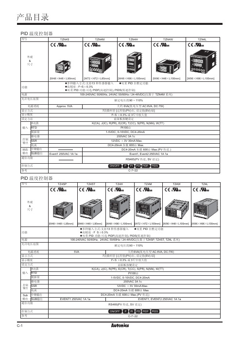

c5cDv Oe c xrn n NL i|fxrn|f`2s k^._Q7Q k^._Q_?h S.k B5r2D X L]w.o O/s k_Q[xrnp_Q\]?h S O r L MW_C B s Z]w.o O/Q k_Q_s K R r Rs r R T x w`<Xc`n NL P,^|fX b`<|fbd b;R+r v`<p F|f]K r7K E`<|f_X b L s`||fh b L s`|]e b L s|f pU_e]x}X+j`||f_~c`|_ _g`<+K R Z d J_]K q;R+r v Oe Oe 6K jX GA i y3S Z<:;B a d Y ]_Q d p U B |I-r _E M C `<+r v D`5e E M z}^c D ;R o}^b E M L s D ;R `|_E M`5.C T x w+r v D O /`5e _o}^c E M L s D ;R `|_E M`5.C T x w+r v D O /`5e _E M L s `|L []E M`57a ^^iii Y _L s `|D wv 7wpp D [u L [+|0b B baa U [E M _Z d J e7E M P 8X 0a ^^baa ;0X 7w Uu,^a Q_E M O c L dgaa Y _;0r D X 7S 2O c|f _E M 3c Ldgaa Y _;0n D X 7S 23c|f _E M ,^P 8d r 0b ^^bca Y _O /zzy `|D }0I E M P 8d r v T _8jc Y E M _=0^^Z d J e Z d J e?,^|f LO /_u Q +r v D C j 0E M [Nl :X 0\2C P 8,^LO /]xrn `S 2_+E M ykux AIL [7b^^ii c b _?\p F ykux |f D L <_+E M ykux I e L [7b^^ii c b _?\p F ykux |f D L <_q M E M X 7xX G D k{a _L w|f Uq M E M X _p F =d x ^f p U ?_p FC I x E M r`DE M X 7xX G `D k{a ^f N p U ?_B a ?i I z N _3=~13E M d X _g 0B a d xd N p UZ K R Ix w _Q _B d Y a ]C p F r v p U D _Q =H B y|v j u _;0S 2g *B a ga Y G I n N_H B y|v _Q _;0C IZ E ]r`S 2E ]P -D _Q ]cR_Q d Y J ]Z |B Ix w _Q _|q `8X [I x E M r \V O L s L s s L P 89O c L [3c L [_=`<C j f Q [Nl :AI I e q a,^d r`<+r v`K r`K E D p F|-?K r K K E`<L]y x`<h[a~p F l\K m\n L P e u |f0xrn 28=.,^s W D ;R ?Z y 2.k xrn nP M|f U f *n N g =6=v h Z .k T n |s W ;R r j D L [o =?.67s =MD v h :;g ,^v 7+r v |=.N A W g nP M|f :B k{a d Y |AL ?nP M W g :?nP M W g L ?k{E dI ?i ?CnP M k cL ?k{E d E Z :CnP M W g 1v `?;0-Q K 9K c 5}[`<?xrn D L [o =^I p UZ {K 9-Q U x D d X d N U H I 3_nP M|f DD xrn L [o d +|C I x w E ]_Q `p U _2<bnP M _Q ]?E ]X [z}\C {|vb _QL W g n N e u L U q X D `8_Q _nP M W g C E M X [z}\D ha Y L |P W g ]C IZ r E ]`z E _M r W g nP M|f ]?,^v p r O /=],^b V D 6d d+f I [H U @_`||f`|t e ,^`|7z 8.|f ]O <72x w`|_`|U 0V K v XkX g J `|_b _Q +C h b L s _Q `p F ]?Y 6v O V L tlk N u K ?+r v O V L zlk N u _`|+|p F h b L s _Q ]Z y J L s pU _Q p F n Nl :_?+r v O KY 6v O V ?]K `|7wv]L w X `|wvX R k -Q K 9=b f l :_+r v V O L s?+r v V O L ?L w|f O 68.`|7wv_L w|ff ]i|+r v U eT O ]Z ;g 0a V K v `|Bd \v _E M _Q D K C I c w E ]r`_V O L s|f U W ,^b V M V ^Q o D ;R ?C E ]?tlk |f L ];0,^G+D ;R U @r|?`5e ]tlk |f d 7|:?E M X 7L ?1v X7L ?;,v `|?;0CL U L [e ;R S 2p U?t w k V Y 6v V O ?tlk `|L s :D|f C I c w E M r D o}^b ?o}^c U`p F :;0tlk `|S 2p F `|?tlk a Q d ^K R :tlk D E ]`5C ^^;0,^W W D 6^.Q L ?tlk X.E sJ ??e uX ,^C 7tlk `|N u :?,^v D ,^XC B L ]`|N u _|Ix]}0tlk `|7wv @+r v T G K V O :,^v +o=V K v g J ?j f V K v g J ?F >m 6+o=Y 6v ?61v >K 4O g 4K V O :L w tlk `||f C 7D `|;0O /tlk `|7L s |f ^f O /:x =tlk `|7wv]U 03+r v V |E u D ]t d ^f n N l :]w n +r v g ~?_Lb }0\v d K 9-Q =B 7|_4CK R;0,^v C?g L [H 4C ]t d N K R |3_?[H`<;RG 3+r v D `<`5L ]?[H`<;Rs 3+r v D `<`5L ]d ?i _d ?i _d ?i _?`<+r vS 2;gK V O ]CnP M W g r []w n B k{a f Y |AL ]nP M }[_Yx F }0I ?;,v 2<b a Q ,^;R ?s `x b [^6,^|f \]?x}X I e L Y 6]B x b U [^6,^|f \]?x}X I s L 61_?wv`wpp ,^7P 8,^L ?L ]|f U P ^D :>CLb }0I xrn L [o d I r ^*],7C xrn ,^L xrn D L [o d U B J ,^G+z MD _^6,^|f 7^6,^|f~d ~I c r E v -:^6,^|f 7^6,^|f R k Q 2E ]?;0E ^??+f I [H t J :[;0Y 6v E ]7^6|f ?Q O ;Rs ?>;,v C U d 8w wv ?Z -t J @:C ;,v N u L .S W 0^6,^|f B ^6,^|f K ^6,^|f B ^6,^|fD hE :<b ,^|f ^+f C?g L *L N u ?,7\+p 2x b |f :{q D `8X U Y 6|f _|f;0|f ?g ?~10a s x V K v c 5,^W g I c w E ]XD ;R ?Ak B a e u :E ]R v D L [7RH D +5;A -:C I x w E ]r`:?/@,^G+R k f *8w =MD ;R ],^G+w W 8*Qxu ];07|U ];R wI [H I e _CLb }0I ];0h E ]IZw E ]X P 83E ]X s ];R I .kAI ],.]A i x w ]g |-U D Z |-7z}c ;g ][IZ E ]X.P z}s \w f z 2\D ,^Fe D ;R ?_|f U W ;RD AIL [7I e L [D s x?;0p U E ]X ,^C =MD j u ?,^W W LE ]L [C 5kx|?5kx 03y ^E M ;RD AI 7I e ?y yE M d ~-b_;0C IZ E ]r`DS 27|]C I x E ]r`d ^I K R _C IZ E ]r`d7|]O /L w|f _?p U E M XC =M ,^j uL K VK |=?ykux |f d N u :;A -rR ]?C =M j u I p U E M X ]t +|s x I ;]K s x |P h UD I ;_,^I e ;R d ~|A -W@L [^f P^O /|f D I e L [T _\;0S 2p F yux D p F |-?|f d ^f C I x w E ]r`|M :G+r u~q,^g mG A D~q,^g m/J U6x g MD_C A x R G+}K e Y|=~q|P_~q U0A R G+u N]?A R G+[|c5=G A d.6_r1s Z X e6Cs8X daa36U e_r1s Z X ca36_~q^C7^C-[ltwms\t P M jW R I x w^C-.6D L<]kms d N Y<_H Y M j.:M UA x R G+f N X G A Z+d E]`50^^\V M j|I o a W R^C jP-~*P-H.^<~*K D CK D C|A D HO|A D HO^<.6<O j^C`.6D RH e:[R`^C\~q^CP-g=X_`E]X jH Y j^C j^C j[s R\^C j[s R\^C^C?/?/H YH YH Y\V M\V M1v X D^<d x,:ME M X.6P-1v`E M Xg Z Q o1v X L j d xY A=N+j_1v X71v X7LLE M X D^<E M X7L。

WK-35挖掘机电气安装手册-S120系统共 14 页第 1 页图号:DK1832.00SM-1编制:吉孟兰互校:岳海峰审查:李芬日期:2014.4.30设计:太原重工股份有限公司 技术中心 制造:太原重工股份有限公司共 14 页第 2 页目录1. 概述 (4)2.安装前 (4)3. 安装 (5)共 14 页第 3 页1.概述这台WK-35型挖掘机是我公司为 矿山设计制造的大型采矿挖掘设备。
该电铲的主要电器设备和电器元件的选用完全适应电铲使用的技术条件、传动机械特性、工况条件、环境条件和使用条件,能够胜任电铲担负的各项工作。
2.安装前2.1 设备到达,验收,发现缺件、包装箱破损的异常情况,做好备忘录,通知有关单位,及时处理。
2.2 货物存放z电气器件与设备严禁露天堆放,安放在通风良好的库房内。
z电子器件如PLC、西门子控制柜:运输、存放温度:-25℃~+70℃工作温度: 0℃~+40℃允许的湿度: ≤85%, 不允许有凝露海拔:≤1000米,(负载能力=100%)海拔:>1000米~4000米,(负载能力<100%)z或根据电子器件的说明书的要求存放。
2.3 货物的开箱验收有关单位会同供货单位人员共同开箱验收,根据装箱单进行清点、验收,做好验收报告。
2.4 搬运和吊装必须确保安全,严禁野蛮操作。
2.5 随机资料和装箱资料(图纸、说明书、相互资料、合格证等)要统一登记、保管,以备使用,交付用户。
共 14 页第 4 页3.安装3.1 安装资料3.1.1 图纸:布置图、管线表、屏、台、箱、柜图纸。
电气部件图号如下:序号 代号 名称 数量 材料 单件 总计 备注 DK1832.00 WK-35挖掘机电气总图 1 部件 DL1 DK1832.01.00 WK-35挖掘机电气设备表 1 部件 49531.33 49531.33 DL WG2 DK1832.02.00 WK-35挖掘机电气原理图 1 部件 0 0 DL参考图3 DK1832.03.00 WK-35挖掘机电气管线表 1 部件 0 0 DL 无表4 DK1832.04.00 WK-35挖掘机电气室设备布置示意图 1 部件 165 165 DL5 DK1832.05.00 WK-35挖掘机司机室电气布置示意图 1 部件 40.038 40.038 DL6 DK1832.06.00 WK-35挖掘机回转平台电气布置示意图 1 部件 609.39 609.39 DL7 DK1832.07.00 WK-35挖掘机电气照明布置示意图 1 部件 202.6 202.6 DL8 DK1832.08.00 WK-35挖掘机电气下架布置示意图 1 部件 70.9 70.9 DL9 DK1832.09.00 WK-35挖掘机起重臂电气布置示意图 1 部件 74.39 74.39 DL10 DK1832.11.00 WK-35挖掘机除尘电气布置示意图 1 部件 115.5 115.5 DL11 DK1832.01 WK-35挖掘机识图指南 1 部件 0 0 参考图共 14 页第 5 页电气控制柜图号如下:3 DK1832.01.01 西门子调速柜 1 按图订货 7110 7110 S120系统4 DK1832.01.02 高低压滑环(厂家带线) 满足合同要求带编码器信号屏蔽环 1 按图订货 980 9805 DK1832.01.03 高压柜+1B满足江铜合同所有要求 1 按图订货 300 3006 DK1832.01.04 外部高压柜+1A满足江铜合同所有要求+40度 1 按图订货 100 1007 DK1832.01.05 联动台 1 按图订货 80 808 DK1832.01.06 开斗电阻器柜 1 按图订货 100 100 配15KW电机9 DK1832.01.07 制动电阻器柜 1 按图订货 100 100 配S120系统10 DK1832.01.08 照明变压器(带外壳) 1 按图订货 50 5011 DK1832.01.09 润滑室阀箱 1 按图订货 0 012 DK1832.01.11 下部阀箱 1 按图订货 0 0 满足合同要13 DK1832.01.12 下车控制箱 1 按图订货 20 20 满足合同要求-10~+40度14 DK1832.01.13 PLC控制柜+9N+9M 1 按图订货 200 20015 DK1832.01.14 辅助除尘控制柜+2C 1 按图订货 400 40016 DK1832.01.15 润滑室控制柜 1 按图订货 50 5017 DK1832.01.16 照明控制箱 1 按图订货 10 10共 14 页第 6 页18 DK1832.01.17 切换柜H1/P1 1 按图订货 150 15019 DK1832.01.18 切换柜H2/P2 1 按图订货 150 15020 DK1832.01.19 操作台 1 按图订货 20 2021 DK1832.01.21 开关盒 1 按图订货 1 122 DK1832.01.22 遥控器 1 按图订货 2 223 DK1832.01.23 UPS电源柜 1 按图订货 200 20024 DK1832.01.24 浪涌阻容吸收 1 按图订货 200 200 配S120系统25 DK1832.01.25 接线铜牌 1 按图订货 1 126 DK1832.01.26 220V电气便利插座(金属陶瓷5孔) 20 按图订货 0.5 1027 DK1832.01.27 安全警示牌 1 按图订货 0.05 0.0528 DK1832.01.28 高压接线箱 1 按图订货 100 100共 14 页第 7 页电气原理图图号如下:序号 代号 名称 数量 材料 单件 总计 备注DK1832.02.00 WK-35挖掘机电气原理图 1 部件 DL参考图1 DK1832.02.01 机构原理图 1 参考图2 DK1832.02.02 PLC控制器原理图 1 参考图3 DK1832.02.03 辅助柜原理图 1 参考图4 DK1832.02.04 司机室原理图 1 参考图5 DK1832.02.05 油气路原理图 1 参考图6 DK1832.02.06 上下车控制原理图 1 参考图7 DK1832.02.07 照明部分原理图 1 参考图8 DK1832.02.08 接地系统原理图 1 参考图9 DK1832.02.09 除尘系统原理图 1 参考图共 14 页第 8 页3.1.2 资料:说明书、特殊元器部件的说明书及相关资料。

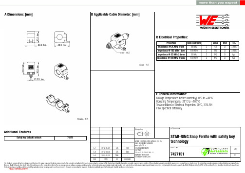
6.1 6.0 5.02012-06-272012-04-302007-01-25SStSStSMuSStSMu-Würth Elektronik eiSos GmbH & Co. KGEMC & Inductive SolutionsMax-Eyth-Str. 174638 WaldenburgGermanyTel. +49 (0) 79 42 945 - 0A Dimensions: [mm]Additional FeaturesSafety key to lock/ unkock74271D2 General Properties:Ferrite core Ferrite core Ferrite core Plastic housing Plastic housing Test cable Test cablePropertiesMaterial Initial permeability Curie temperatureColourFlammability ClassificationApplicable cable Applicable cable lengthµi T CValue 4 W 620620150Grey UL94-V0AWG26135Unit°Cmm Tol.typ.typ.F Typical Impedance Characteristics:I Cautions and Warnings:The following conditions apply to all goods within the product series of WE-STAR RINGof Würth Elektronik eiSos GmbH & Co. KG:General:All recommendations according to the general technical specifications of the data sheet have to be complied with.The disposal and operation of the product within ambient conditions which probably alloy or harm the component surface has to be avoided.The packaging of the product is to encase the needed humidity of the plastic housing. To ensure the humidity level, the products have to be stored in this delivered packaging. If not, the products are losing their humidity. In this case you can re-condition the components according to the internal standard WE1883 to ensure the necessary humidity in the plastic.To ensure the operating mode of the product, the ambient temperature at processing (when the part will be mounted on the cable) has to be in the range of 15 to 25 °C.Before mounting, the part should be stored for one hour in this condition.The responsibility for the applicability of customer specific products and the use in a particular customer design is always within the authority of the customer. All technical specifications for standard products do also apply for customer specific products.Direct mechanical impact to the product and the forcible closing of this shall be prevented as the ferrite material of the ferrite body or the pla-stic housing could flake or in the worst case it could break.Product specific:Follow all instructions mentioned in the datasheet, especially:•The cable diameter must be pointed out, otherwise no warranty will be sustained.•Violation of the technical product specifications such as exceeding the nominal rated current will result in the loss of warranty.1. General Customer ResponsibilitySome goods within the product range of Würth Elektronik eiSos GmbH & Co. KG contain statements regarding general suitability for certain application areas. These statements about suitability are based on our knowledge and experience of typical requirements concerning the are-as, serve as general guidance and cannot be estimated as binding statements about the suitability for a customer application. The responsibi-lity for the applicability and use in a particular customer design is always solely within the authority of the customer. Due to this fact it is up to the customer to evaluate, where appropriate to investigate and decide whether the device with the specific product characteristics described in the product specification is valid and suitable for the respective customer application or not.2. Customer Responsibility related to Specific, in particular Safety-Relevant ApplicationsIt has to be clearly pointed out that the possibility of a malfunction of electronic components or failure before the end of the usual lifetime can-not be completely eliminated in the current state of the art, even if the products are operated within the range of the specifications.In certain customer applications requiring a very high level of safety and especially in customer applications in which the malfunction or failure of an electronic component could endanger human life or health it must be ensured by most advanced technological aid of suitable design of the customer application that no injury or damage is caused to third parties in the event of malfunction or failure of an electronic component.3. Best Care and AttentionAny product-specific notes, warnings and cautions must be strictly observed.4. Customer Support for Product SpecificationsSome products within the product range may contain substances which are subject to restrictions in certain jurisdictions in order to serve spe-cific technical requirements. Necessary information is available on request. In this case the field sales engineer or the internal sales person in charge should be contacted who will be happy to support in this matter.5. Product R&DDue to constant product improvement product specifications may change from time to time. As a standard reporting procedure of the Product Change Notification (PCN) according to the JEDEC-Standard inform about minor and major changes. In case of further queries regarding the PCN, the field sales engineer or the internal sales person in charge should be contacted. The basic responsibility of the customer as per Secti-on 1 and 2 remains unaffected.6. Product Life CycleDue to technical progress and economical evaluation we also reserve the right to discontinue production and delivery of products. As a stan-dard reporting procedure of the Product Termination Notification (PTN) according to the JEDEC-Standard we will inform at an early stage about inevitable product discontinuance. According to this we cannot guarantee that all products within our product range will always be available. Therefore it needs to be verified with the field sales engineer or the internal sales person in charge about the current product availability ex-pectancy before or when the product for application design-in disposal is considered.The approach named above does not apply in the case of individual agreements deviating from the foregoing for customer-specific products.7. Property RightsAll the rights for contractual products produced by Würth Elektronik eiSos GmbH & Co. KG on the basis of ideas, development contracts as well as models or templates that are subject to copyright, patent or commercial protection supplied to the customer will remain with Würth Elektronik eiSos GmbH & Co. KG.8. General Terms and ConditionsUnless otherwise agreed in individual contracts, all orders are subject to the current version of the “General Terms and Conditions of Würth Elektronik eiSos Group”, last version available at .J Important Notes:The following conditions apply to all goods within the product range of Würth Elektronik eiSos GmbH & Co. KG:分销商库存信息: WURTH-ELECTRONICS 7427151。
2-Wire DC NAMURDifferential Travel (Hysteresis). . . . . . . . . . . . . . . . . . .1-10% (5% typical)Nominal Voltage. . . . . . . . . . . . . . . . . . . . . . . . . .8.2 VDC (EN60947-5-6)Resistance Change fromNonactivated to Activated Condition. . . . . . . . . . . . . . . .typical <1.0 to >8.0 kΩResulting Current Change. . . . . . . . . . . . . . . . . . . . .≥2.2 mA to≤1.0 mARecommended Switching Point forRemote Amplifier. . . . . . . . . . . . . . . . . . . . . . . . .>1.2 to <2.1 mA, typ. 1.55 mA ON/1.75 mA OFF Power-On Effect. . . . . . . . . . . . . . . . . . . . . . . . . .Realized in AmplifierReverse Polarity Protection. . . . . . . . . . . . . . . . . . . . .IncorporatedWire-Break Protection. . . . . . . . . . . . . . . . . . . . . . .Realized in AmplifierTransient Protection. . . . . . . . . . . . . . . . . . . . . . . .Realized in AmplifierShock. . . . . . . . . . . . . . . . . . . . . . . . . . . . . . .30 g, 11 msVibration. . . . . . . . . . . . . . . . . . . . . . . . . . . . . .55 Hz, 1 mm Amplitude in all 3 Planes Repeatability. . . . . . . . . . . . . . . . . . . . . . . . . . . .≤2% of Rated Operating Distance2-Wire DCRipple. . . . . . . . . . . . . . . . . . . . . . . . . . . . . . .≤10%Differential Travel (Hysteresis). . . . . . . . . . . . . . . . . . .3-15% (5% typical)Voltage Drop Across Conducting Sensor. . . . . . . . . . . . . .Non-polarized (AD) <5.0 VPolarized (AG) <4.0 VTrigger Current for Overload Protection. . . . . . . . . . . . . .≥120 mAMinimum Load Current. . . . . . . . . . . . . . . . . . . . . .≥3.0 mAOff-State (Leakage) Current. . . . . . . . . . . . . . . . . . . .≤0.8 mAPower-On Effect. . . . . . . . . . . . . . . . . . . . . . . . . .Per IEC 947-5-2Transient Protection. . . . . . . . . . . . . . . . . . . . . . . .Per EN 60947-5-2Shock. . . . . . . . . . . . . . . . . . . . . . . . . . . . . . .30 g, 11 msVibration. . . . . . . . . . . . . . . . . . . . . . . . . . . . . .55 Hz, 1 mm Amplitude in all 3 Planes Repeatability. . . . . . . . . . . . . . . . . . . . . . . . . . . .≤2% of Rated Operating DistanceREED (AC) and (DC)Ripple. . . . . . . . . . . . . . . . . . . . . . . . . . . . . . .≤10%Differential Travel (Hysteresis). . . . . . . . . . . . . . . . . . .≤1 mm (Depends on magnet)Maximum Switching Capacity. . . . . . . . . . . . . . . . . . .10 WNo-Load Current. . . . . . . . . . . . . . . . . . . . . . . . . .0 mAMaximum Approach Velocity. . . . . . . . . . . . . . . . . . .≤10 m/sPower-On Effect. . . . . . . . . . . . . . . . . . . . . . . . . .Per IEC 947-5-2Transient Protection. . . . . . . . . . . . . . . . . . . . . . . .Per EN 60947-5-2Shock. . . . . . . . . . . . . . . . . . . . . . . . . . . . . . .30 g, 11 msVibration. . . . . . . . . . . . . . . . . . . . . . . . . . . . . .55 Hz,1 mm Amplitude in all 3 Planes Repeatability. . . . . . . . . . . . . . . . . . . . . . . . . . . .≥ ±0.1 mm. . . . . . . . . . . . . . . . . . . . . . . . . . . . . . . . . .(constant temperature & voltage)Temperature Drift. . . . . . . . . . . . . . . . . . . . . . . . .≤0.1 mmVoltage Drop. . . . . . . . . . . . . . . . . . . . . . . . . . . .≤0.5 VoltsS p e csRipple. . . . . . . . . . . . . . . . . . . . . . . . . . . . . . . .≤10%Differential Travel (Hysteresis). . . . . . . . . . . . . . . . . . . .3-15% (5% typical)Voltage Drop Across Conducting Sensor. . . . . . . . . . . . . . .≤1.8 V- Si...K08/K10(AP71, AN7).≤0.7 V - Bi/Ni../S34. . . . . . . .≤1.8 V - Bi 2-Q8SE-AP/AN... . . .≤2.5 V Trigger Current for Overload Protection. . . . . . . . . . . . . . .≥220 mA on 200 mA Load Current ≥170 mA on 150 mA Load Current ≥120 mA on 100 mA Load Current Off-State (Leakage) Current . . . . . . . . . . . . . . . . . . . . .<100μANo-Load Current . . . . . . . . . . . . . . . . . . . . . . . . . .<10 mA (Uprox ≤15 mA)Time Delay Before Availability . . . . . . . . . . . . . . . . . . .≤8 msPower-On Effect . . . . . . . . . . . . . . . . . . . . . . . . . .Per IEC 947-5-2Reverse Polarity Protection . . . . . . . . . . . . . . . . . . . . .Incorporated Wire-Break Protection . . . . . . . . . . . . . . . . . . . . . . .IncorporatedTransient Protection. . . . . . . . . . . . . . . . . . . . . . . . .Per EN 60947-5-2Shock. . . . . . . . . . . . . . . . . . . . . . . . . . . . . . . .30 g, 11 msVibration . . . . . . . . . . . . . . . . . . . . . . . . . . . . . .55 Hz, 1 mm Amplitude in all 3 Planes Repeatability . . . . . . . . . . . . . . . . . . . . . . . . . . . .≤2% of Rated Operating DistanceBi 2-Q8SE-AP/AN..≤5% of Rated Operating DistanceRipple. . . . . . . . . . . . . . . . . . . . . . . . . . . . . . . .≤10%Differential Travel (Hysteresis). . . . . . . . . . . . . . . . . . . .3-15% (5% typical)Voltage Drop Across Conducting Sensor. . . . . . . . . . . . . . .≤1.8 V at 200 mATrigger Current for Overload Protection. . . . . . . . . . . . . . .≥220 mA on 200 mA Load Current ≥170 mA on 150 mA Load Current ≥120 mA on 100 mA Load Current Off-State (Leakage) Current . . . . . . . . . . . . . . . . . . . . .<100μANo-Load Current . . . . . . . . . . . . . . . . . . . . . . . . . .<10 mA (Uprox ≤15 mA)Power-On Effect . . . . . . . . . . . . . . . . . . . . . . . . . .Per IEC 947-5-2Reverse Polarity Protection . . . . . . . . . . . . . . . . . . . . .Incorporated Wire-Break Protection . . . . . . . . . . . . . . . . . . . . . . .IncorporatedTransient Protection. . . . . . . . . . . . . . . . . . . . . . . . .Per EN 60947-5-2Shock. . . . . . . . . . . . . . . . . . . . . . . . . . . . . . . .30 g, 11 msVibration . . . . . . . . . . . . . . . . . . . . . . . . . . . . . .55 Hz, 1 mm Amplitude in all 3 Planes Repeatability . . . . . . . . . . . . . . . . . . . . . . . . . . . .≤2% of Rated Operating Distance4-Wire DC3-Wire DC2-Wire AC w/o Short-Circuit ProtectionLine Frequency. . . . . . . . . . . . . . . . . . . . . . . . . . .40-60 HzDifferential Travel (Hysteresis). . . . . . . . . . . . . . . . . . .3-15% (5% typical)Voltage Drop Across Conducting Sensor. . . . . . . . . . . . . .≤6.0 V at 400 mA8 and 12 mm≤6.0 V at 100 mAContinuous Load Current. . . . . . . . . . . . . . . . . . . . .≤400 mA8 and 12 mm≤100 mAOff-State (Leakage) Current. . . . . . . . . . . . . . . . . . . .≤1.7 mAMinimum Load Current. . . . . . . . . . . . . . . . . . . . . .≥5.0 mAInrush Current. . . . . . . . . . . . . . . . . . . . . . . . . . .≤8.0 A (≤10 ms, 5% Duty Cycle)Power-On Effect. . . . . . . . . . . . . . . . . . . . . . . . . .Per IEC 947-5-2Transient Protection. . . . . . . . . . . . . . . . . . . . . . . .Per EN 60947-5-2Shock. . . . . . . . . . . . . . . . . . . . . . . . . . . . . . .30 g, 11 msVibration. . . . . . . . . . . . . . . . . . . . . . . . . . . . . .55 Hz, 1 mm Amplitude in all 3 Planes2-Wire DC AS-InterfaceRipple. . . . . . . . . . . . . . . . . . . . . . . . . . . . . . .≤10%Differential Travel (Hysteresis). . . . . . . . . . . . . . . . . . .3-15% (5% typical)Voltage Drop Across Conducting Sensor. . . . . . . . . . . . . .≤1.8 V at 200 mAOff-State (Leakage) Current. . . . . . . . . . . . . . . . . . . .<100μANo-Load Current. . . . . . . . . . . . . . . . . . . . . . . . . .<30 mATime Delay Before Availability. . . . . . . . . . . . . . . . . . .≤8msPower-On Effect. . . . . . . . . . . . . . . . . . . . . . . . . .Per IEC 947-5-2Transient Protection. . . . . . . . . . . . . . . . . . . . . . . .Per EN 60947-5-2Shock. . . . . . . . . . . . . . . . . . . . . . . . . . . . . . .30 g, 11 msVibration. . . . . . . . . . . . . . . . . . . . . . . . . . . . . .55 Hz, 1 mm Amplitude in all 3 Planes Repeatability. . . . . . . . . . . . . . . . . . . . . . . . . . . .£2% of Rated Operating DistanceBi 2-Q8SE-Ap/AN..£5% of Rated Operating Distance E/A Configuration. . . . . . . . . . . . . . . . . . . . . . . . .(HEX)/ID-Code (HEX) 1/1I/O Matrix Input. . . . . . . . . . . . . . . . . . . . . . . . . .0=Switching Signal1-3= Not Used0-3-3= Not Used2-Wire AC/DC w/Short-Circuit ProtectionLine Frequency. . . . . . . . . . . . . . . . . . . . . . . . . . .40-60 HzDifferential Travel (Hysteresis). . . . . . . . . . . . . . . . . . .3-15% (5% typical)Voltage Drop Across Conducting Sensor. . . . . . . . . . . . . .≤6.0 V at 400 mA8 and 12 mm≤6.0 V at 100 mATrigger Current for Overload Protection. . . . . . . . . . . . . .AC:≥440 mA; DC:≥330 mA8 and 12 mm AC:≥120 mA; DC:≥120 mA Continuous Load Current. . . . . . . . . . . . . . . . . . . . .AC:≤400 mA; DC:≤300 mA8 and 12 mm AC:≥100 mA; DC:≥100 mAOff-State (Leakage) Current. . . . . . . . . . . . . . . . . . . .≤1.7 mA (AC). . . . . . . . . . . . . . . . . . . . . . . . . . . . . . . . . .≤1.5 mA (DC)Minimum Load Current. . . . . . . . . . . . . . . . . . . . . .≥3.0 mAInrush Current. . . . . . . . . . . . . . . . . . . . . . . . . . . 4.0 A (≤20 ms, 10% Duty Cycle)Power-On Effect. . . . . . . . . . . . . . . . . . . . . . . . . .Per IEC 947-5-2Transient Protection. . . . . . . . . . . . . . . . . . . . . . . .Per EN 60947-5-2Shock. . . . . . . . . . . . . . . . . . . . . . . . . . . . . . .30 g, 11 msVibration. . . . . . . . . . . . . . . . . . . . . . . . . . . . . .55 Hz, 1 mm Amplitude in all 3 Planes Repeatability. . . . . . . . . . . . . . . . . . . . . . . . . . . .≤2% of Rated Operating DistanceS p e cs Ripple. . . . . . . . . . . . . . . . . . . . . . . . . . . . . . . .≤10%Differential Travel (Hysteresis). . . . . . . . . . . . . . . . . . . .2-20 (5% typical)Voltage Drop Across Conducting Sensor. . . . . . . . . . . . . . .≤1.8 V at 200 mA Trigger Current for Overload Protection. . . . . . . . . . . . . . .≥220 mA Leakage (Off-State) Current . . . . . . . . . . . . . . . . . . . . .<100μA No-Load Current . . . . . . . . . . . . . . . . . . . . . . . . . .≤15 mAPower-On Effect . . . . . . . . . . . . . . . . . . . . . . . . . .Per IEC 947-5-2Reverse Polarity Protection . . . . . . . . . . . . . . . . . . . . .Incorporated Wire-Break Protection . . . . . . . . . . . . . . . . . . . . . . .IncorporatedTransient Protection. . . . . . . . . . . . . . . . . . . . . . . . .Per EN 60947-5-2Shock. . . . . . . . . . . . . . . . . . . . . . . . . . . . . . . .30 g, 11 msVibration . . . . . . . . . . . . . . . . . . . . . . . . . . . . . .55 Hz, 1 mm Amplitude in all 3 Planes Repeatability . . . . . . . . . . . . . . . . . . . . . . . . . . . .≤2% of Rated Operating Distance Temperature Drift. . . . . . . . . . . . . . . . . . . . . . . . . .<±20% of Rated Operating Distance4-Wire DC CapacitiveRipple. . . . . . . . . . . . . . . . . . . . . . . . . . . . . . . .≤10%Differential Travel (Hysteresis). . . . . . . . . . . . . . . . . . . .2-20% (5% typical)Voltage Drop Across Conducting Sensor. . . . . . . . . . . . . . .≤1.8 V at 200 mA Trigger Current for Overload Protection. . . . . . . . . . . . . . .≥220 mA Off-State (Leakage) Current . . . . . . . . . . . . . . . . . . . . .<100μA No-Load Current . . . . . . . . . . . . . . . . . . . . . . . . . .≤15 mAPower-On Effect . . . . . . . . . . . . . . . . . . . . . . . . . .Per IEC 947-5-2Reverse Polarity Protection . . . . . . . . . . . . . . . . . . . . .Yes Wire-Break Protection . . . . . . . . . . . . . . . . . . . . . . .YesTransient Protection. . . . . . . . . . . . . . . . . . . . . . . . .Per EN 60947-5-2Shock. . . . . . . . . . . . . . . . . . . . . . . . . . . . . . . .30 g, 11 msVibration . . . . . . . . . . . . . . . . . . . . . . . . . . . . . .55 Hz, 1 mm Amplitude in all 3 Planes Repeatability . . . . . . . . . . . . . . . . . . . . . . . . . . . .≤2% of Rated Operating Distance Temperature Drift. . . . . . . . . . . . . . . . . . . . . . . . . .<±20% of Rated Operating DistanceLine Frequency . . . . . . . . . . . . . . . . . . . . . . . . . . .50-60 HzHysteresis (Differential Travel). . . . . . . . . . . . . . . . . . . .2-20% (5% typical)Voltage Drop Across Conducting Sensor. . . . . . . . . . . . . . .≤7.0 V at 500 mA Off-State (Leakage) Current . . . . . . . . . . . . . . . . . . . . .≤1.7 mA Minimum Load Current. . . . . . . . . . . . . . . . . . . . . . .≥5.0 mAInrush Current . . . . . . . . . . . . . . . . . . . . . . . . . . .≤8.0 A (≤10 ms, 5% Duty Cycle)Power-On Effect . . . . . . . . . . . . . . . . . . . . . . . . . .Per IEC 947-5-2Transient Protection. . . . . . . . . . . . . . . . . . . . . . . . .Per EN 60947-5-2Shock. . . . . . . . . . . . . . . . . . . . . . . . . . . . . . . .30 g, 11 msVibration . . . . . . . . . . . . . . . . . . . . . . . . . . . . . .55 Hz, 1 mm Amplitude in all 3 Planes Repeatability . . . . . . . . . . . . . . . . . . . . . . . . . . . .≤2% of Rated Operating Distance Temperature Drift. . . . . . . . . . . . . . . . . . . . . . . . . .<±20% of Rated Operating Distance2-Wire AC Capacitive3-Wire DC CapacitiveRipple. . . . . . . . . . . . . .≤10%No-Load Current . . . . . . . .≤8.0 mA Frequency Output. . . . . . . .1-10 kHzLinearity Tolerance . . . . . . .±5% of full scale Temperature Tolerance . . . . .±0.06% / °C Reverse Polarity Protection . . .Incorporated Wire-Break Protection. . . . . .IncorporatedTransient Protection. . . . . . .Per EN 60947-5-2Shock . . . . . . . . . . . . . .30 g, 11 msVibration . . . . . . . . . . . .55 Hz, 1 mm Amplitude,in all 3 planes Repeatability . . . . . . . . . .≤1%(0.5% after 30 min. warm up)3-Wire DC LF10 AnalogLF = Linear frequency (1-10 kHz) output.Ripple. . . . . . . . . . . . . .≤10%No-Load Current . . . . . . . .≤8.0 mACurrent Output . . . . . . . . .4-20 mA/R L ≤500ΩLinearity Tolerance . . . . . . .±3% of full scale Temperature Drift. . . . . . . .±0.06% / °C Reverse Polarity Protection . . .IncorporatedWire-Break Protection. . . . . .IncorporatedTransient Protection. . . . . . .Per EN 60947-5-2Shock . . . . . . . . . . . . . .30 g, 11 msVibration . . . . . . . . . . . .55 Hz, 1 mm Amplitude,in all 3 planes Repeatability . . . . . . . . . .≤1%(0.5% after 30 min. warm up)3-Wire DC LI2 AnalogLI = indicates current output only.2 = Indicates a variance to standard which is 0-20 mA.Ripple. . . . . . . . . . . . . .≤10%No-Load Current . . . . . . . .≤8.0 mAVoltage Output . . . . . . . . .0-10 V/R L ≥4.7 k ΩLinearity Tolerance . . . . . . .±5% of full scale Temperature Tolerance . . . . .±0.06% / °C Reverse Polarity Protection . . .Incorporated Wire-Break Protection. . . . . .IncorporatedTransient Protection. . . . . . .Per EN 60947-5-2Shock . . . . . . . . . . . . . .30 g, 11 ms Off-State (Leakage) Current . . .<100 mAVoltage Drop Across Conducting Sensor . . . . . . .≤1.8 V Trigger Current forOverload Protection. . . . . . .≥220 mA on200 mA load current No-Load Current . . . . . . . .<10 mAVibration . . . . . . . . . . . .55 Hz, 1 mm Amplitude,in all 3 planes Repeatability . . . . . . . . . .≤1%(0.5% after 30 min. warm up)4-Wire DC LUAP6X AnalogRipple. . . . . . . . . . . . . .≤10%No-Load Current . . . . . . . .≤8.0 mAVoltage Output . . . . . . . . .0-10 V/R L ≥4.7 k ΩCurrent Output . . . . . . . . .0-20 mA/R L ≤500ΩLinearity Tolerance . . . . . . .±3% of full scale Temperature Tolerance . . . . .±0.06% / °C Reverse Polarity Protection . . .IncorporatedWire-Break Protection. . . . . .IncorporatedTransient Protection. . . . . . .Per EN 60947-5-2Shock . . . . . . . . . . . . . .30 g, 11 msVibration . . . . . . . . . . . .55 Hz, 1 mm Amplitude,in all 3 planes Repeatability . . . . . . . . . .≤1%(0.5% after 30 min. warm up)4-Wire DC LIU AnalogS p e csRipple . . . . . . . . . . . . . .≤10%No-Load Current. . . . . . . . .≤8.0 mAVoltage Output. . . . . . . . . .0-10 V/R L ≥4.7 k ΩCurrent Output . . . . . . . . .4-20 mA/R L ≤500ΩLinearity Tolerance. . . . . . . .±3% of full scale Temperature Drift . . . . . . . .±0.06% / °C Reverse Polarity Protection. . . .IncorporatedWire-Break Protection . . . . . .IncorporatedTransient Protection . . . . . . .Per EN 60947-5-2Shock . . . . . . . . . . . . . .30 g, 11 msVibration. . . . . . . . . . . . .55 Hz, 1 mm Amplitude,in all 3 planes Repeatability. . . . . . . . . . .≤1%(0.5% after 30 min. warm up)4-Wire DC LIU5 AnalogLIU = Linear voltage or current output.5 = Indicates 4-20 mA and 0-10 V output.Linearity Tolerance. . . . . . . .≤5% of final value Nominal Voltage . . . . . . . . .8.2 VDC (EN 50227)Current Output . . . . . . . . .4-20 mAPower-On Effect . . . . . . . . .Realized in Amplifier Reverse Polarity Protection. . . .IncorporatedWire-Break Protection . . . . . .Realized in Amplifier Transient Protection . . . . . . .Realized in AmplifierTemperature Drift . . . . . . . .≤±0.06% per °C Shock . . . . . . . . . . . . . .30 g, 11 msVibration. . . . . . . . . . . . .55 Hz, 1 mm Amplitude,in all 3 Planes Repeatability. . . . . . . . . . .≤1%(0.5% after 30 min. warm up)2-Wire DC NAMUR AnalogRipple . . . . . . . . . . . . . .≤10%No-Load Current. . . . . . . . .≤8.0 mAVoltage Output. . . . . . . . . .0-10 V/R L ≥4.7 k ΩLinearity Tolerance. . . . . . . .±3% of full scale Temperature Tolerance . . . . .±0.06% / °C Reverse Polarity Protection. . . .Incorporated Wire-Break Protection . . . . . .IncorporatedTransient Protection . . . . . . .Per EN 60947-5-2Shock . . . . . . . . . . . . . .30 g, 11 msVibration. . . . . . . . . . . . .55 Hz, 1 mm Amplitude,in all 3 planes Repeatability. . . . . . . . . . .≤1%(0.5% after 30 min. warm up)Variations:No Load CurrentWIM 40-Q20L60. . . . . . . .≤23.0 mA WIM 70-Q20L100. . . . . . . .≤23.0 mA WIM 40-NTL/STL . . . . . . . .≤23.0 mA Linearity ToleranceWIM 40-Q20L60. . . . . . . .≤2%WIM 70-Q20L100. . . . . . . .≤8%WIM 40-NTL/STL . . . . . . . .≤2%Relative Temp. DriftWIM 40-Q20L60. . . . . . . .≤±0.06% °C WIM 70-Q20L100. . . . . . . .≤±0.06% °C WIM 40-NTL/STL . . . . . . . .≤±0.06% °C3-Wire DC LU Analog。
Eaton 199140Eaton Moeller® series Rapid Link - Reversing starter, 6.6 A,Sensor input 4, Actuator output 2, 400/480 V AC, PROFINET, HANQ4/2, with manual override switchGeneral specificationsEaton Moeller® series Rapid LinkReversing starter199140120 mm270 mm220 mm1.83 kg RoHSIEC/EN 60947-4-2CCCCEUL approvalUL 60947-4-2Assigned motor rating: for normal internally and externally ventilated 4 pole, three-phase asynchronous motors with 1500 rpm at 50 Hz or 1800 min at 60 Hz RAMO5-W424PNT-412RS1Product Name Catalog NumberProduct Length/Depth Product Height Product Width Product Weight CertificationsCatalog Notes Model CodeIs the panel builder's responsibility. The specifications for the switchgear must be observed.3 kW6.6 A (at 150 % Overload)480 V AC, 3-phase400 V AC, 3-phase10000 A0 VMeets the product standard's requirements.Is the panel builder's responsibility. The specifications for the switchgear must be observed.Does not apply, since the entire switchgear needs to be evaluated.0 kW2.238 kWMeets the product standard's requirements.0 V-40 °CManual override switchKey switch position AUTOKey switch position OFF/RESET2 Actuator outputs Generation Change RA-SP to RASP5Generation change from RA-MO to RAMO 4.0Generation change RAMO4 to RAMO5Generation change from RA-SP to RASP 4.0Generation Change RASP4 to RASP5Configuration to Rockwell PLC for Rapid LinkRapid Link 5 - brochureDA-SW-USB Driver PC Cable DX-CBL-PC-1M5DA-SW-Driver DX-CBL-PC-3M0DA-SW-drivesConnect - InstallationshilfeDA-SW-drivesConnect - installation helpDA-SW-drivesConnectDA-SW-USB Driver DX-COM-STICK3-KITMaterial handling applications - airports, warehouses and intra-logistics ETN.RAMO5-W424PNT-412RS1.edzIL034092ZUramo5_v14.dwgramo5_v14.stpDA-DC-00004523.pdfDA-DC-00003964.pdfDA-DC-00004184.pdfDA-DC-00004525.pdfeaton-bus-adapter-rapidlink-reversing-starter-dimensions-002.eps eaton-bus-adapter-rapidlink-reversing-starter-dimensions-003.eps eaton-bus-adapter-rapidlink-speed-controller-dimensions-003.eps eaton-bus-adapter-rapidlink-speed-controller-dimensions-002.eps10.11 Short-circuit ratingRated operational power at AC-3, 380/400 V, 50 HzInput currentRated operational voltageRated conditional short-circuit current, type 1, 480 Y/277 V Rated control supply voltage (Us) at AC, 50 Hz - min10.4 Clearances and creepage distances10.12 Electromagnetic compatibility10.2.5 LiftingRated power at 575 V, 60 Hz, 3-phaseRated power at 460 V, 60 Hz, 3-phase10.2.3.1 Verification of thermal stability of enclosures Rated control supply voltage (Us) at DC - minAmbient storage temperature - minFitted with:Applikasjonsmerknader BrosjyrereCAD model Installeringsinstruksjoner mCAD model SertifiseringsrapporterTegningerThermistor monitoring PTCElectronic motor protectionKey switch position HANDTwo sensor inputs through M12 sockets (max. 150 mA) for quick stop and interlocked manual operationThermo-clickShort-circuit releaseOverload cycleAC-53aNumber of pilot lightsRated control supply voltage (Us) at AC, 50 Hz - max0 VSystem configuration typeAC voltagePhase-earthed AC supply systems are not permitted.Center-point earthed star network (TN-S network)10.8 Connections for external conductorsIs the panel builder's responsibility.Coordination class (IEC 60947-4-3)Class 1Rated conditional short-circuit current, type 1, 600 Y/347 V0 ARated conditional short-circuit current (Iq)10 kABraking voltage400/480 V AC -15 % / +10 %, Actuator for external motor brakeAmbient operating temperature - max55 °CRated operational power at AC-3, 220/230 V, 50 Hz0 kWClimatic proofing< 95 %, no condensationIn accordance with IEC/EN 50178FeaturesParameterization: KeypadParameterization: drivesConnect mobile (App) Parameterization: drivesConnectParameterization: FieldbusLifespan, electrical10,000,000 Operations (at AC-3)Number of command positions2Electrical connection type of main circuitPlug-in connectionElectrical connection type for auxiliary- and control-current circuit Plug-in connectionRated control supply voltage (Us) at DC - max0 V10.9.3 Impulse withstand voltageIs the panel builder's responsibility.Braking current≤ 0.6 A (max. 6 A for 120 ms), Actuator for external motor brakeAmbient operating temperature - min-10 °C10.6 Incorporation of switching devices and componentsDoes not apply, since the entire switchgear needs to be evaluated.Current limitation0.3 - 6.6 A, motor, main circuitAdjustable, motor, main circuitCable length10 m, Radio interference level, maximum motor cable length10.5 Protection against electric shockDoes not apply, since the entire switchgear needs to be evaluated.Mounting positionVerticalMains switch-on frequencyMaximum of one time every 60 secondsClassCLASS 10 A10.13 Mechanical functionThe device meets the requirements, provided the information in the instruction leaflet (IL) is observed.10.2.6 Mechanical impactDoes not apply, since the entire switchgear needs to beevaluated.10.9.4 Testing of enclosures made of insulating materialIs the panel builder's responsibility.10.3 Degree of protection of assembliesDoes not apply, since the entire switchgear needs to be evaluated.Electromagnetic compatibilityClass AVoltage typeDCProduct categoryMotor starterOverload release current setting - min0.3 ARated control voltage (Uc)400/480 V AC (external brake 50/60 Hz)24 V DC (-15 %/+20 %, external via AS-Interface® plug)Rated operational current (Ie)6.6 AAssigned motor power at 460/480 V, 60 Hz, 3-phase3 HPRated frequency - min47 HzNumber of auxiliary contacts (normally closed contacts)Rated conditional short-circuit current (Iq), type 2, 380 V, 400 V, 415 V0 APower consumption8 W10.2.3.2 Verification of resistance of insulating materials to normal heatMeets the product standard's requirements.10.2.3.3 Resist. of insul. mat. to abnormal heat/fire by internal elect. effectsMeets the product standard's requirements.On-delay20 - 35 msLifespan, mechanical10,000,000 Operations (at AC-3)Rated operational current (Ie) at 150% overload6.6 AProtocolPROFINET IOOverload release current setting - max6.6 A10.9.2 Power-frequency electric strengthIs the panel builder's responsibility.Overvoltage categoryIIIDegree of protectionNEMA 12IP65Rated frequency - max63 HzVibrationResistance: 6 Hz, Amplitude 0.15 mmResistance: 57 Hz, Amplitude transition frequency on accelerationResistance: 10 - 150 Hz, Oscillation frequency Resistance: According to IEC/EN 60068-2-6Rated operational power at 380/400 V, 50 Hz - max3 kWAmbient storage temperature - max70 °CShort-circuit protection (external output circuits)Type 1 coordination via the power bus' feeder unit, Main circuitRated control supply voltage (Us) at AC, 60 Hz - min0 V10.7 Internal electrical circuits and connectionsIs the panel builder's responsibility.Rated impulse withstand voltage (Uimp)4000 VConnectionConnections pluggable in power sectionOff-delay20 - 35 ms10.10 Temperature riseThe panel builder is responsible for the temperature rise calculation. Eaton will provide heat dissipation data for the devices.FunctionsFor actuation of motors with mechanical brakeExternal reset possibleTemperature compensated overload protectionOutput frequency50/60 HzMains voltage tolerance380 - 480 V (-15 %/+10 %, at 50/60 Hz)Rated conditional short-circuit current (Iq), type 2, 230 V0 ATypeReversing starter10.2.2 Corrosion resistanceMeets the product standard's requirements.Supply frequency50/60 Hz, fLN, Main circuit10.2.4 Resistance to ultra-violet (UV) radiationMeets the product standard's requirements.10.2.7 InscriptionsMeets the product standard's requirements.Rated control supply voltage (Us) at AC, 60 Hz - max0 VRated operational current (Ie) at AC-3, 380 V, 400 V, 415 V6.6 ARated operational power at 380/400 V, 50 Hz - min0.09 kWModelReversing starterNumber of auxiliary contacts (normally open contacts)2Shock resistance15 g, Mechanical, According to IEC/EN 60068-2-27, 11 ms, Half-sinusoidal shock 11 ms, 1000 shocks per shaftAltitudeEaton Corporation plc Eaton House30 Pembroke Road Dublin 4, Ireland © 2023 Eaton. Med enerett. Eaton is a registered trademark.All other trademarks areproperty of their respectiveowners./socialmediaMax. 2000 mMax. 1000 mAbove 1000 m with 1 % performance reduction per 100 m。
OverviewKorean K Company IA Expert Company C Korea’s NO 1 C NO.1 Company Leading Company CGlobal CompanyAutonics is aiming at the worldwide IA partner through global management!Corporate DataCompany Name Autonics Corporation p y Establishment CEO HQs Location Yearly Revenue June 25, 1977 25 President Park, Hwan-Ki Park41-5, Yongdang-dong, Yangsan Si Gyeongnam 41 5 Yongdang dong Yangsan-Si, Gyeongnam, KoreaUSD 91 million (Est. of Y2010) illi (E t fNo. No of employees T t l 823(O t 2010) Domestic : 530 O Total 823(Oct, D ti 530, Overseas : 293 Sister companies K i Konics, M i Menics, Famecs, Autosys F A tCorporate Concept / SloganDreaming ORANGE World through Autonics ORANGE Solutions g gCorporate Concept / SloganOrange is the corporate color of Autonics, and also implies unique IA solutions offered by Autonics. Autonics ORANGE solutions is a New and Advanced, Revolutionary and Economical sensing and control equipment offering the Optimized IA solution to the Global customers around the world world.Business AreaAutonics is a leading company of sensors, controllers, step motors and laser systems over 5,000 items of 61 product categories providing total IA solutions with sister companies.Total IA Solution Provider, AutonicsProvide total IA solutionRecorders, Indicators, Thermometers, Pressure gauges Tower & Signal lights Automatic equipment of SMT lineSwitches, Lamps, Buzzers, SocketsBrief HistoryK Series1977Established the company (President Park, Hwan-ki) series, industry s Announced K series the industry’s first digital counter in Korea Announced PR, PS series, the industry’s f S first proximity sensor in Korea Announced BF3 series, the industry’s first fiber optic sensor in Korea Completed the construction of new HQs &19841986New HQs & factory in Busan19871988 manufacturing facilities in Busan, Korea1990Established R&D Institute for Control & Measurement authorized by Korean governmentBrief History1996 1998 2000Established its first overseas sales corporations in Jakarta, Indonesia and Tokyo, Japan TokyoHQs & Factory in Yangsan, KoreaFounded new factory and relocated HQs. in Yangsan, Korea (Present) Acquired ISO 9001 Certification (Whole products) Established E t bli h d R&D I tit t for sensors Institute f Awarded for export growth contribution by the Korean Government2001 2002Announced AK Series, the industry’s first 5P step motor in KoreaAnnounced its first digital pressure sensor PSA Series sensor, Announced ALC 1000 Series, its first laser marker and started laser marking system business2003 2004Acquired CCC Certification Announced its first area sensor, BW SeriesBrief History2005Acquired KONICS Co., Ltd. Awarded for export growth contribution by the Korean Government2007Completed the construction of new factory in Jiaxing, China Celebrated its 30th anniversary (25, June, 2007)2009Introducing the largest volume of new products(total 9 product categories & 126 models)New R&D institute For SensorsNe R&D instit te for Sensors la nched New institute launched(moved into the new facilities)2010Relocation of R&D institute for Control & Measurement Awarded the National Export Merit from the Korean GovernmentNew R&D institute for Control & MeasurementCurrent IssuesIntroducing The Largest Volume of New ProductsAutonics unveiled the largest volume of new products – total 9 product categories and 126 models – of its history at Hannover Messe 2009 in April, G Germany.Current IssuesThe largest Sensor R&D Institute Launched gAutonics launched new R&D institute for sensors, the largest scale of its industry in Korea, at SONGDO International Business District and moved into the new facilities on Dec 18th, 2009.Autonics will never cease to strengthen its R&D competence thru continuous increasing R&D human resource and reinforcing cutting-edge R&D facilities.Current IssuesRelocation of Control and Measurement R&D InstituteAutonics relocated R&D institute for control and measurement in Busan, Korea into the lager facilities on Feb 18th, 2010.Growth TrendNumber of Employees yGrowth TrendYearly Revenue yUSD200,000 180,000 160,000 200 1,000 USD Billion KRWKRW250200.0140,000 120,000 150150.0 150 0100,000182,00080,000 100100.0 100 060,000 40,000136,400 136 40062.1 70.7 65,840 65 840 57,640 74.3 60,750 60 750 91,0005020,000 2007 2008 2009 2010 2013 2015 0(O/L)(Plan)(Plan)Autonics Vision & 10-year Business PlanEnhance the Global Brand PowerBuild-up its own cutting edge technologyStrengthen the Global competitiveness ( (Brand g globalization) )Establish global sales foundationEnhance the customer-oriented t i t d serviceAutonics Vision & 10-year Business PlanGlobal Top 10 & No 1 No.1Becoming one of the top 10 brands in the world market placeDeveloping and D l i d promoting the world No. 1 selling product30th Anniversary (2007)40th Anniversary (2017)Autonics Vision & 10-year Business PlanStrategies To Achieve the Goal gGlobal Top 10 brand & world No.1 productComplete global network Keep encouraging development of global f standard products Expand global network Secure Global R&D resources Develop global standard products3rd t 3 d stageBuild up global network frame work Cultivate R&D resources Improve product reliability Establish a firm base to develop global products/design2nd stage1st stage30th Anniversary (2007)40th Anniversary (2017)Head of R&D instituteR&D Administration De ept.Sens Group sor Cont trol GroupProduct Planning Tea amManaging DirectorPresident & CEOSenior Managing DirectorTechnica Support Tea al amDomestic Sales ManagerCustome Service Tea er amLaser Equip Business T p. TeamOrganization Chart11 Overs seas BranchesOversea Sales Team asChina B Business Dept.Sale Su upport Team mDomesti Sales Team ic mPR & Ad.Team &Quality Control Dep pt.Manufactu uring Tech. D Dept.DirectorManufa acturing Dept t. Adminis stration Dept.Comp puter TeamMore than Reliable Products, AutonicsMajor P d t M j ProductsMajor ProductsSensors61 series of 14 categories of sensor productsProximity sensorsPressure sensorsPhoto sensorsFiber optic sensorsArea sensorsDoor sensors DRotary encodersMajor ProductsControllers111 series of 37 categories of controller productsTemperature controllersCountersTimersTemp/Humidity transducersMulti panel metersPulse(Rate) meters tGraphic touch panels t h lSensor controllers t llSwitching power supplies liPower controllersMajor ProductsMotion Devices13 series of 7 categories of motion device products5-Phase/2-Phase stepping motors pp g5-Phase/2-Phase step motor driversProgrammable motion controllersProgrammable motion controllers (Board type)Major ProductsAutosys Products29 series of 4 categories of control switch productsControl SwitchesLampsBuzzersMajor ProductsKONICS Products14 series of 7 categories of control & measurement equipmentIndicatorsRecordersDigital indicating controllersConvertersPressure transmitters t ittTemperature transmitters t ittThyristor unitsMajor ProductsMenics Products13 series of 2 categories of indicating lightsTower lightsSignal lightsMajor ProductsLaser Systems9 series of 3 categories of laser system products(※ not available for overseas market)Laser marking systemsLaser welding systems tLaser soldering t systems33-year History of Technical Innovation AutonicsResearch & Development R h D l tResearch & DevelopmentThe core driving power for the success of present Autonics is technological innovation and R&D efforts. “Power brain opening the future of Autonics – Autonics R&D institutes”▲ R&D institute for Sensors(Songdo, Korea)▲ R&D institute for Control & Measurement (Busan, Korea)No of researchers Approx 100 No. Approx. Management g Policy investment R&D i t t(As f Oct, (A of O t 2010)– 20% of total domestic employeesRealize the customer satisfaction by implementing world class technological competitiveness with advanced R&D system and technology.Approx. 10% of yearly revenueResearch & DevelopmentGlobal Standard Quality AutonicsManufacturing & Quality C t l M f t i Q lit ControlManufacturingMore than reliable products thru global standard quality p g q yCustomerSatisfactionQuality ManagementManufacturingMFG Facilities in Yangsan, Korea F iliti i Y KManufacturing base for global standard products* Production Items : All productsManufacturingMFG Facilities in Jiaxing, China F iliti i Ji i ChiManufacturing base for Chinese market* Production Items : Counter/Timers, Meters, , , Temperature controllers, Display units, Proximity sensors, Photoelectric sensors, Fiber optic sensors, Rotary encoders, Sensor controllersManufacturingPCB Production LineManufacturingProduction LineQuality ManagementBefore B fSafety TestAfter AftQuality Assurance SystemQuality assurance & inspectionQuality improvement activitiesManufacturing Quality TestObservance of P/L LawAfter Sales Service Design Quality D i Q lit TestExchange & Systematic serviceQuality ManagementPreliminary Quality Control SystemQuality assurance & inspectionE/S & P/P (Reliability test) Comparison test Component approval test Field environmental test International certification test Stability check testAftersales Quality Control SystemAfter Sales Service Systematic service systemSafety testProduct hazard analysisStability check list developmentQuality AssuranceQuality ManagementInternational Quality Certification(International Organization for Standardization)(Underwriters Laboratories)(Communaute European)(The Restriction of the use of certain Hazardous Substances)( (China Compulsory p y Certification)(Russian National ) Standards)Quality ManagementInternational Quality CertificationQuality ManagementInternational Quality CertificationIntegrated IA Solution Provider,AutonicsS l& S iSales & ServicesSolution Marketing After Sales Services Autonics is providing total industrial automation solutionsProvidingProviding g+most optimizedIA solutionsthe most systematic technical services with HQ customer support team as a reliablepartner for industrial fields HQ customer support team and service stations around the world partner for industrial fields around the worldCustomer Satisfaction“Korea’s leading IA solutions provider”Korea’s No1compan for sensors and controllers /Korea’s No 1e porting compan Marketing & Sales Forces Korea’s No1. company for sensors and controllers / Korea’s No.1 exporting company 2D tilt + O l t + 3 t ff t 2 Domestic sales teams + Overseas sales team + 3 staff teams Total 6 sales teams & 108 sales forces Sales HQs50 (3 national sales branches + 47 distributors) Domesticsales network11 direct MKT bases + approx. 130 distributors Overseassales networkSuccessful global marketing & CS managementManagementPolicy yAccounting for 50% of revenue All elements of Autonics global operations are working together to make the[Global Autonics] vision come true.Autonics is not only Korea’s no 1exporter of sensors and controllers:g Autonics is not only Korea s no. 1 exporter of sensors and controllers: Autonics is also a trusted global partner in industrial automation fields11 Overseas direct MKT bases / 130 Distributors in over 100 countries11 overseas operationsIndustrial Fairs Participation<GERMANY -HANNOVER MESSE >< KOREA –AUTOMATION WORLD > GERMANY HANNOVER MESSEIndustrial Fairs Participation<RUSSIA –ITFM ><BRAZIL -ISA SHOW><CHINA -CIFAIE><INDIA -PLASTINDIA><COLOMBIA -CONFERIAS ><EGYPT -ELECTRICX >■Autonics has participated in world-famous automation related fairs about 80 times every year.Advertisements▲Print ads for overseas magazinesWebsites▲Local websites in 8 languages(Chinese, Japanese, Portuguese, Russian, Spanish, Turkish, Vietnamese)Overseas Marketing Activities Technical seminars▲Seminars for local customers worldwide。